processing, bonding the individual windings as a single unit and presenting a compositestructure to the short circuit forces, rendering the windings very capable against such forces. Inthe following calculations, weight age has not been given to this aspect. Hence, the actualfigures, if any, will be much better and safer compared to the derived values. Even though thehigh voltage winding is symmetrically placed with respect to the low voltage winding, for
calculations certain asymmetry is assumed, which in reality is not true. By the very nature ofthis assumed asymmetry, the calculated figures are purely hypothetical and since the stressesare lower even at this assumed asymmetry, they will be much lower under practical conditions.
2. Rating of the Transformer
All electrical systems are susceptible to short circuits and the abnormal current levelsthey create. These currents can produce considerable thermal and mechanical stresses inelectrical distribution equipment. Therefore, it's important to protect personnel and equipment
by calculating short-circuits currents during system upgrade and design. The rating of thetransformer for which the short circuit withstand capability is calculated are
1500KVA 22KV/415V 39.37/2086.81A Short Circuit Impedance is 6% Vector groupDyn11
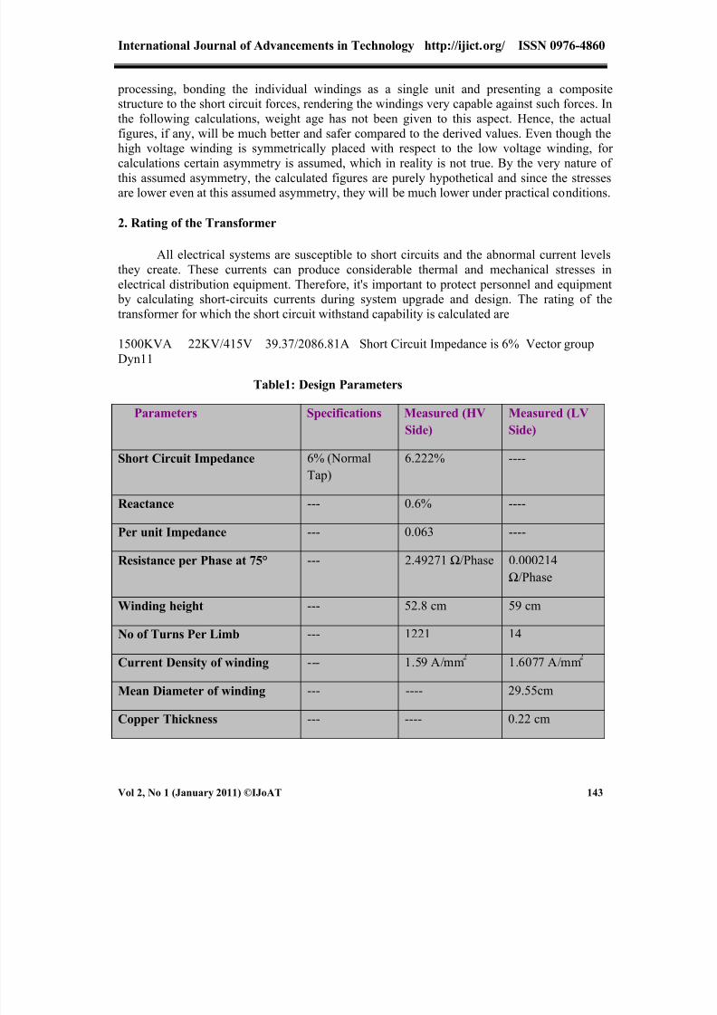
Table1: Design Parameters
Parameters Specifications Measured (HVSide)
Measured (LVSide)
Short Circuit Impedance 6% (NormalTap)
6.222% ----
Reactance --- 0.6% ----
Per unit Impedance --- 0.063 ----
Resistance per Phase at 75° --- 2.49271 Ω/Phase 0.000214Ω/Phase
Winding height --- 52.8 cm 59 cm
No of Turns Per Limb --- 1221 14
Current Density of winding --- 1.59 A/mm 1.6077 A/mm
Mean Diameter of winding --- ---- 29.55cm
Copper Thickness --- ---- 0.22 cm
8/12/2019 Calculations for Short Circuit Withstand Capability of a Distribution Transformer
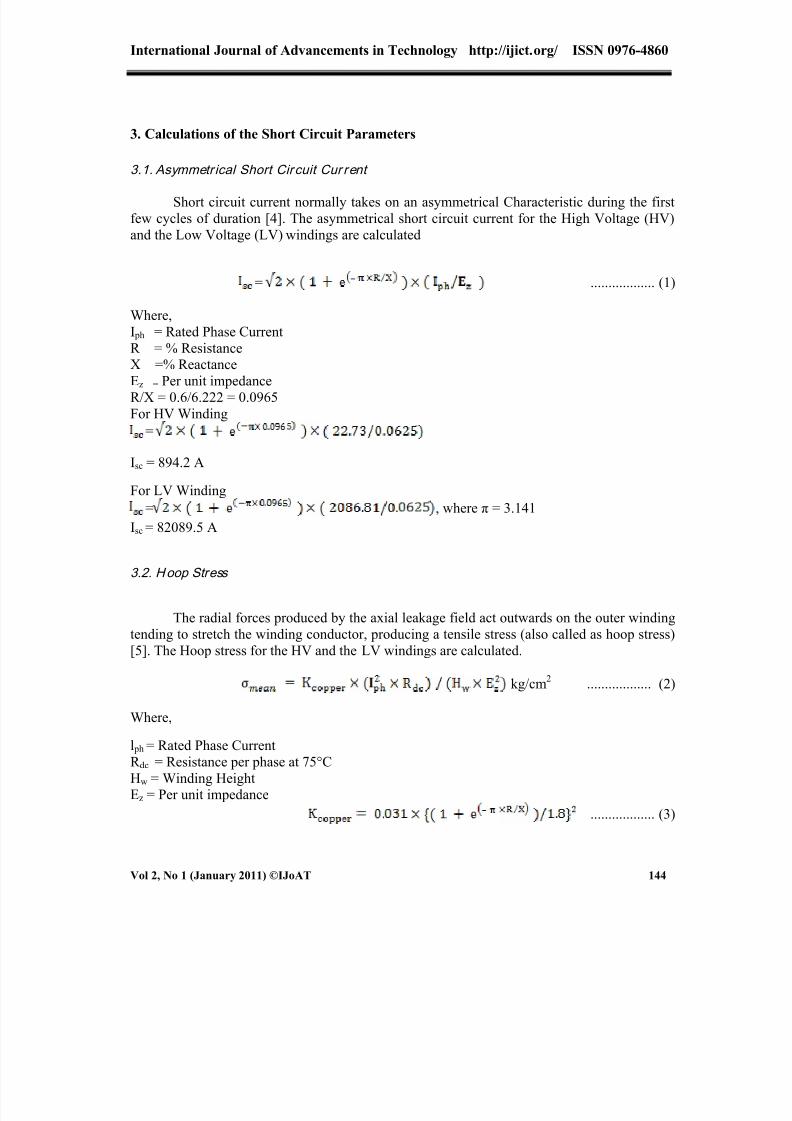
Short circuit current normally takes on an asymmetrical Characteristic during the firstfew cycles of duration [4]. The asymmetrical short circuit current for the High Voltage (HV)and the Low Voltage (LV) windings are calculated
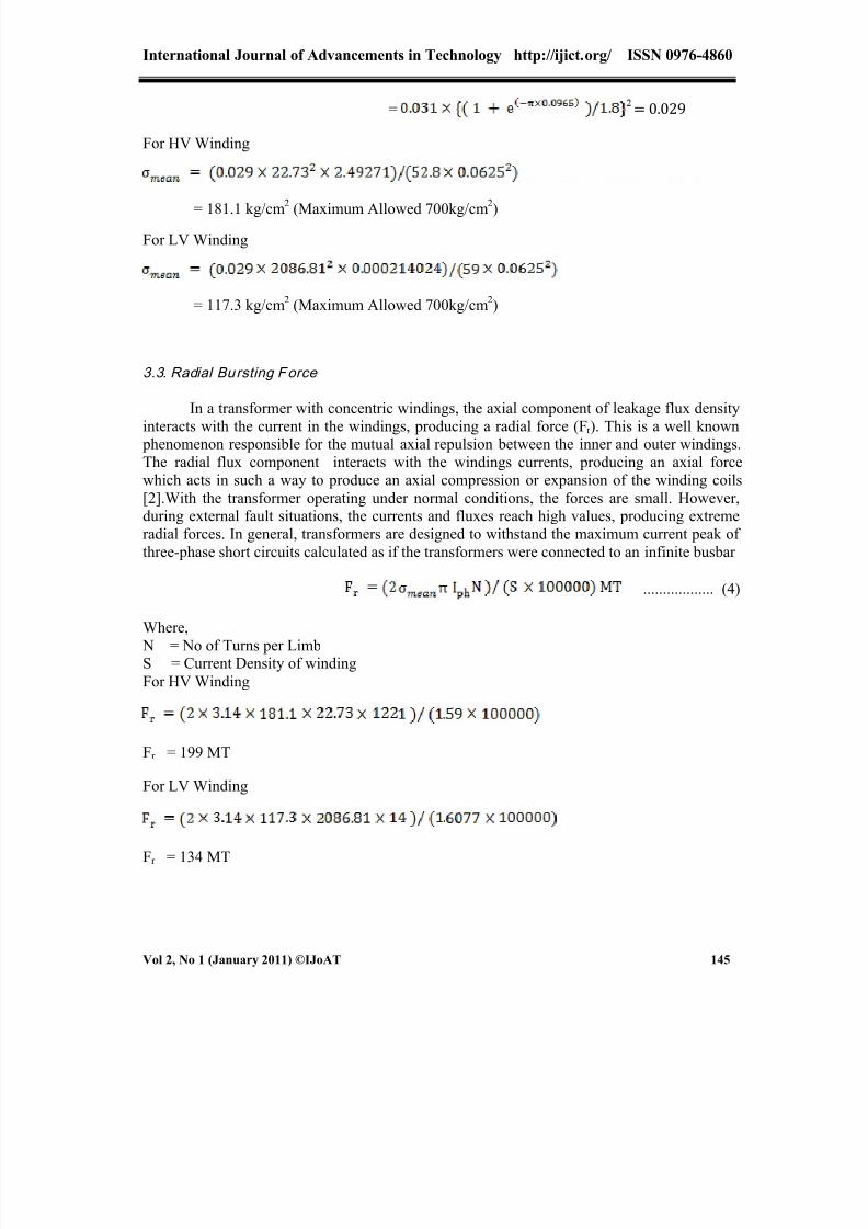
The radial forces produced by the axial leakage field act outwards on the outer windingtending to stretch the winding conductor, producing a tensile stress (also called as hoop stress)[5]. The Hoop stress for the HV and the LV windings are calculated.
kg/cm 2 .................. (2)
Where,
l ph = Rated Phase CurrentR dc = Resistance per phase at 75°CHw = Winding HeightEz = Per unit impedance
.................. (3)
8/12/2019 Calculations for Short Circuit Withstand Capability of a Distribution Transformer
3.4. Supports to be provided in and for L V winding
The spacers are inserted to provide the necessary strength to the winding against theradial forces. Every conductor has radial oil flow due to the use of radial spacers for conductorsupport [6]. Spacer thickness can be changed to allow improved cooling and decreasedwinding rise or directed oil flow within the winding can be applied to improve theeffectiveness of the winding conductor cooling
Nos. .................. (5)
Where,
= Hoops Stress in kg/cm 2
Dm = Mean Diameter of winding in cm
T = Copper Thickness in cm
E = Young s Modules for copper , which is 1.13 x 10 6 Pascal
= 0.4 Nos
Here no supports are necessary. Actual support provided in the form of Partinax cylinderwhich is continuous. LV cooling duct are spaced at 19 mm (14 mm between the supports).There are 29 such supports. Hence support for LV winding is more than adequate.
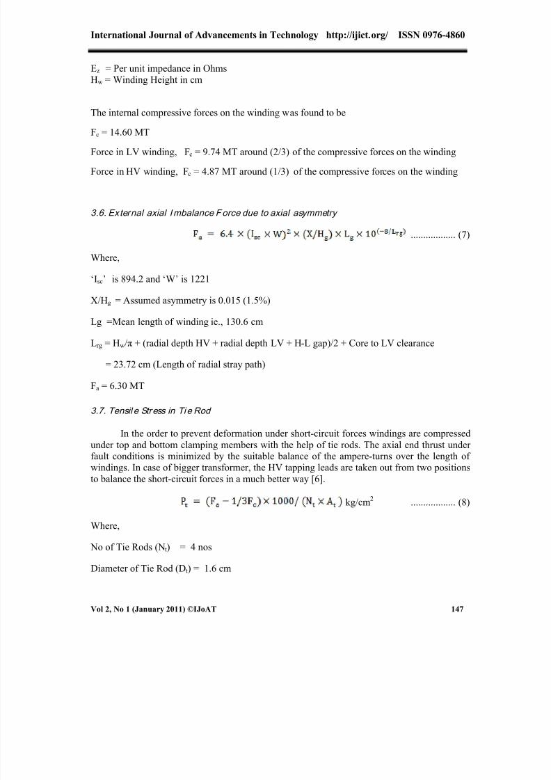
3.5. In tern al compressive For ces on wi nding
The inner winding experiences radial forces acting inwards tending to collapse or crushit, producing a compressive stress. Due to the fringing of the leakage field at the ends of thewindings, the axial component of the field reduces resulting into smaller radial forces in these
regions [7]
MT .................. (6)
Where,Sn = Rated kVA
8/12/2019 Calculations for Short Circuit Withstand Capability of a Distribution Transformer
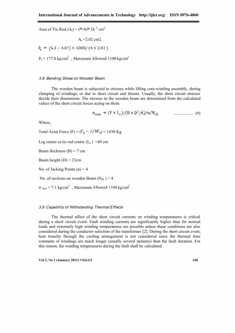
P t = 177.0 kg/cm 2 , Maximum Allowed 1100 kg/cm 2
3.8. Bending Stress on Wooden Beam
The wooden beam is subjected to stresses while lifting core-winding assembly, duringclamping of windings, or due to short circuit end thrusts. Usually, the short circuit stressesdecide their dimensions. The stresses in the wooden beam are determined from the calculatedvalues of the short circuit forces acting on them.
σ max = 7.1 kg/cm 2 , Maximum Allowed 1100 kg/cm 2
3.9. Capabili ty of Withstanding Thermal E ff ects
The thermal affect of the short circuit currents on winding temperatures is criticalduring a short circuit event. Fault winding currents are significantly higher than for normalloads and extremely high winding temperatures are possible unless these conditions are alsoconsidered during the conductor selection of the transformer [2]. During the short circuit event,heat transfer through the cooling arrangement is not considered since the thermal timeconstants of windings are much longer (usually several minutes) than the fault duration. Forthis reason, the winding temperatures during the fault shall be calculated
8/12/2019 Calculations for Short Circuit Withstand Capability of a Distribution Transformer
The author wishes to thank Mr. P.Peter Durairaj , Mrs M.Glory Sobana , Mr. P.Jeba Peace, Nokia Siemens, India,
and Dr. M.T Nicholas, Principal, LITES for their support and encouragement.
References
[1] IEC 60076 -1 , “Power Transformers ” – Part 1: General, 2000[2] M.S Naidu, V.Kamaraju : “High Voltage Engineering ” , Third Edition , Tata McGraw-Hill ,2007[3] IEC 60060-1 , “High Voltage Test Techiques ” – Part 1: General, 1989[4] IEEE/ANSI Standards C57.12.00 “IEEE Standard General Requirements for Liquid Immersed
Distribution , Power, Regulating Transformers“, 2000 [5] G. Bertagnolli ,“Short – Circuit Dutyof Power Transformers ” Italy , 1991[6] IEEE/ANSI Standards C57.123 “ IEEE Guide for Transformer Loss Mea surement“, 2002 [7] ABB , “Testing of Power Transformers“,Zurich,2003 [8] E. Kuffel , W.S Zaengl, “High Voltage Engineering Fundamentals “, Frankfurt, 1984


![Welcome [] Walker.pdf · IDC Fault current hAssumptions for simple fault current calculations: hIgnore cable between switchgear and fault hCable between transformer and fault? hIgnore](https://static.documents.pub/doc/80x56/5e9b23eeaae6672497011698/welcome-walkerpdf-idc-fault-current-hassumptions-for-simple-fault-current.jpg)


