Calibrating a multi-arm multi-sensor robot: A Bundle Adjustment Approach Vijay Pradeep, Kurt Konolige & Eric Berger Abstract Complex robots with multiple arms and sensors need good calibration to perform precise tasks in unstructured environments. The sensors must be calibrated both to the manipulators and to each other, since fused sensor data is often needed. We propose an extendable framework that combines measurements from the robot’s various sensors (proprioceptive and external) to calibrate the robot’s joint offsets and external sensor locations. Our approach is unique in that it accounts for sen- sor measurement uncertainties, thereby allowing sensors with very different error characteristics to be used side by side in the calibration. The framework is general enough to handle complex robots with kinematic components, including external sensors on kinematic chains. We validate the framework by implementing it on the Willow Garage PR2 robot, providing a significant improvement in the robot’s cali- bration. 1 INTRODUCTION For many robot tasks, such as sensor fusion or vision-based manipulation, the sen- sors and manipulators of a robot must be calibrated; that is, their inter-relationships must be well-characterized. This calibration is extremely important for complex robots, with many sensors and degrees of freedom, that perform tasks in an un- structured environment, such as grasping objects sitting on a table (See Fig 1). If the pose of the camera is not known relative to the robot’s arm, then the arm could completely miss the object or even collide with it. Not only do the sensors have to be calibrated to the manipulator, but the sensors also have to be calibrated to each other. Otherwise, the object detection algorithms could fail when combining data from multiple sensors. Vijay Pradeep, Kurt Konolige & Eric Berger Willow Garage Inc., Menlo Park, CA, USA. e-mail: {vpradeep,konolige,berger}@willowgarage.com 1
Transcript
Calibrating a multi-arm multi-sensor robot:A Bundle Adjustment Approach
Vijay Pradeep, Kurt Konolige & Eric Berger
Abstract Complex robots with multiple arms and sensors need good calibration toperform precise tasks in unstructured environments. The sensors must be calibratedboth to the manipulators and to each other, since fused sensor data is often needed.We propose an extendable framework that combines measurements from the robot’svarious sensors (proprioceptive and external) to calibrate the robot’s joint offsetsand external sensor locations. Our approach is unique in that it accounts for sen-sor measurement uncertainties, thereby allowing sensors with very different errorcharacteristics to be used side by side in the calibration. The framework is generalenough to handle complex robots with kinematic components, including externalsensors on kinematic chains. We validate the framework by implementing it on theWillow Garage PR2 robot, providing a significant improvement in the robot’s cali-bration.
1 INTRODUCTION
For many robot tasks, such as sensor fusion or vision-based manipulation, the sen-sors and manipulators of a robot must be calibrated; that is, their inter-relationshipsmust be well-characterized. This calibration is extremely important for complexrobots, with many sensors and degrees of freedom, that perform tasks in an un-structured environment, such as grasping objects sitting on a table (See Fig 1). Ifthe pose of the camera is not known relative to the robot’s arm, then the arm couldcompletely miss the object or even collide with it. Not only do the sensors have tobe calibrated to the manipulator, but the sensors also have to be calibrated to eachother. Otherwise, the object detection algorithms could fail when combining datafrom multiple sensors.
Vijay Pradeep, Kurt Konolige & Eric BergerWillow Garage Inc., Menlo Park, CA, USA.e-mail: {vpradeep,konolige,berger}@willowgarage.com
1
2 Vijay Pradeep, Kurt Konolige & Eric Berger
Fig. 1 The PR2 grasping an object. Fig. 2 A calibrated PR2 plugging itself in.
Complex robots can also pose many challenges for the calibration procedure.The robot may have many different sensors, and each sensor often has very differ-ent error characteristics. For instance, a laser rangefinder detects points in 3D verydifferently than a stereocamera, and a camera’s precision in resolving points is verydependent on its focal length. To complicate things further, if the camera is mountedon a robot arm or other actuated linkage, then the linkage’s error characteristics mustalso be incorporated into the sensor’s uncertainties.
Although there exist special-purpose calibration procedures, such as camera-camera [14] or camera-arm [6] registration, there is no general-purpose frameworkfor calibrating all of the sensors and actuators of a robot together while account-ing for each sensor’s individual error characteristics. In this paper, we present justsuch a framework, implement it on the PR2 mobile manipulation platform [18], andexperimentally show the effects in a precision plug-in task (Figure 2).
Our method is formulated as a general optimization problem, modeled after thebundle adjustment framework of computer vision [15]. It has the following charac-teristics:
• We estimate a set of system parameters together with poses of targets in theworld. Any sensor that can observe points in the world and is modeled by ameasurement equation with gaussian error characteristics can be used with ourmethod.
• We can easily combine sensor measurements from different coordinate spaces,for example, from lasers (3D points) and cameras (2D image projections). Thetrade-off in accuracy of sensors is handled in a theoretically sound way via co-variances in the measurement equations.
• We generalize every sensor as being attached to an actuated linkage. This lets usvery naturally deal with the “hand-in-eye” case, where a camera is attached to arobot’s end effector.
We are currently using measurements from kinematic chains, stereo cameras,monocular cameras, and tilting lasers to estimate joint angle offsets, joint gear re-ductions, sensor poses, and stereo baselines. The framework is flexible enough to
Calibrating a multi-arm multi-sensor robot: A Bundle Adjustment Approach 3
allow additional types of sensors and any associated parameters, so long as we canmodel the expected readings of the new sensors and approximate the sensor errorsas gaussians.
Our semi-automated data collection routine takes about 20 minutes to run on thePR2, and the nonlinear optimization takes a further 25 minutes when estimating pa-rameters for 6 cameras, 1 tilting laser sensor, and 16 joints. The software describedin this paper is available under an open source license, and is available online.1
2 RELATED WORK
Many people have developed specific techiques for pairwise calibration betweensensors. In [19], Zhang used line constraints to calibrate a 2D laser rangefinder to acamera. Similar work was done by Unnikrishnan in [16], but this focused on usingplane constraints from a 3D laser rangefinder system.
Given that industrial robots have been performing tasks in structured environ-ments for quite a while, robot arm calibration has also been around for a long time.Chapter 3 of An’s text [1] provides a procedure to estimate an arm’s kinematic pa-rameters using external sensing. Lorsakul’s work in [11] uses Arun’s SVD basedpose fitting technique [2] to compute the relative position between a dental tool and3D position sensor. Chen’s method in [5] avoids singularities by using transforma-tion matrices to calibrate an arm using end effector pose measurements. Once again,all of these approaches ignore covariances. In [17], Wampler calibrates an arm byattaching a 6 DOF sensor to its end effector and accounts for uncertainties in jointangles; however, this is not a general purpose approach.
A more complex case is when an actuated camera system needs to be calibrated.This is often called a “hand-in-eye” system and has been addressed by Horaud [8]and Daniilidis [6]. Both works estimate the pose of the camera in the end effector ofa manipulator, while assuming that the end effector pose can be perfectly measuredusing forward kinematics. In many cases, estimating just this single transform isinsufficient, since the manipulator’s kinematics might also need to be calibrated.
In [10], Le generates 3D data from groups of sensors, and then uses cartesianspace error metrics to compare these groups. However, many robot systems don’tnecessarily have clear 3D groups, and the resulting 3D measurements can have veryeccentric error covariances. Le’s work ignores these covariances, which could leadto biased results. Hollerbach’s work in [7] does in fact explicitly model the covari-ances of errors in closed loops between sensors and actuators. However, the numberof loops needed to fully descibe the system scales poorly with the number of sen-sors, since every possible pair of sensors will need its own loop defined.
There has been previous work in trying to determine the topology of the system,such as Sturm’s work in [13]. In our proposed framework, however, we assume thatwe know the system topology and simply want to improve system’s accuracy.
1 http://www.ros.org/wiki/pr2 calibration
4 Vijay Pradeep, Kurt Konolige & Eric Berger
Needing to estimate the relative poses of several cameras or many poses of asingle moving camera is a somewhat common problem. The photogrammetry andcomputer vision communities often solve this by jointly estimating the set of cameraposes along with 3D features that are detected by some set of the cameras. Thisapproach, commonly called bundle adjustment [15], relies on having a gaussiancovariance model for each camera measurement. The system can then be solvedfor as a large nonlinear least squares problem. However, there is no reason that thebundle adjustment approach should only estimate camera poses, and there is noreason for it to only use cameras measurements. Our work is inspired by the bundleadjustment approach, and generalizes it to estimate robot system parameters usingmeasurements from various types of sensors.
3 Problem Formulation
3.1 General Requirements
By measuring a point in the world with multiple sensors, we create constraints thatallow us estimate the parameters that relate these sensors in the robot system. For ourexperiments, we use checkerboard targets because they proved to give very robustdetection and registration across sensors.
Suppose a tilting laser and actuated camera both detect a checkerboard in theworld (See Fig 3a). This combined measurement then gives us information to helpestimate the pose transform between the kinematic linkage and each sensor as wellas kinematic parameters such as joint offsets. Another case is when an actuatedcamera detects a checkerboard being held in the robot’s hand. Depending on wherethe camera is attached to the robot, different parts of the robot are constrained, asshown in Fig 3b and Fig 3c.
Our experiments currently use three types of sensors: tilting lasers, kinematicchains, and actuated monocular cameras. An actuated stereo camera can be treatedas two actuated monocular cameras, and a fixed camera can be treated as an ac-tuated camera with an empty linkage. We require that for a given a set of systemparameters and a point in the world, we must be able to model the sensor’s expectedmeasurement of this point. Additionally, we assume gaussian error characteristicsfor each sensor, and thus error covariances must be computed for each sensor.
Suppose that sensor i measures point j in the world. We can then define a mea-surement equation as follows:
zi j = h(x, p j)+wi j (1)wi j ∼ N(0,Σi j). (2)
In (1), given a set of robot system parameters x, h computes the expected obser-vation of point p j. The measurement noise wi j is defined in (2), and is sampled froma zero-mean gaussian distribution with a covariance of Σi j.
Calibrating a multi-arm multi-sensor robot: A Bundle Adjustment Approach 5
Cam
Laser Rangefinder
Torso
LeftArm
RightArm
CamLeftArm
RightArm
Torso
Cam
A B C
Fig. 3 (A) Actuated camera and tilting laser detecting a checkerboard. (B) Left forearm cameradetecting a checkerboard held in the left arm. (C) Right forearm camera detecting a checkerboardheld in the right arm. Each case constrains different parts of the system (See green line).
3.2 Optimization
Given the set of many measurements from multiple sensors of multiple views oftargets in the world, we want to find the maximum likelihood estimate of robotparameters and poses of targets that best explains our measurements. In order tocompare our our expected measurements to our actual measurements, we rewritethe measurement equation (1) to define the residual r:
ri j = h(x, p j)− zi j . (3)
Given that we now have a residual from (3) and covariances from (2) for eachmeasurement equation, we can then formulate the maximum likelihood estimateproblem as a nonlinear, bundle-adjustment-like optimization, where we jointly esti-mate x and the set of all p js (which we will call P):
x, P = argminx,P
∑i j
rTi jΣ
−1i j ri j . (4)
Note that in (4), we are summing over unitless quantities. Even though the residu-als themselves generally have units, scaling them by Σ
−1i j makes them unitless. This
provides some insight into our approach: Without covariances, we wouldn’t be ableto combine residuals from different types of sensors. That is, it wouldn’t make senseto compare a distance sensor’s error (in meters) with a camera’s error (in pixels).
Sensors can often be modeled in multiple coordinate spaces, and our approachlets us choose the coordinate space that is most convenient, so long as we can calcu-late an error covariance in that space. As we’ll see in sections 4.1 and 4.3, kinematicchains and tilting lasers can both be conveniently modeled in cartesian space.
Given the straightforward minimization formulation, we can now solve this usinga standard Levenberg-Marquardt optimizer, such as scipy’s optimize library [9].
6 Vijay Pradeep, Kurt Konolige & Eric Berger
4 Sensor Measurement Types
For each type of sensor in our robot system, we need to define a measurement equa-tion, along with the noise characteristics of the sensor. To simplyify the optimizationprocedure, we approximate every sensor to have gaussian noise. For the PR2, we de-fine 3 types of sensors: kinematic chains, actuated cameras, and tilting lasers.
4.1 Kinematic Chain
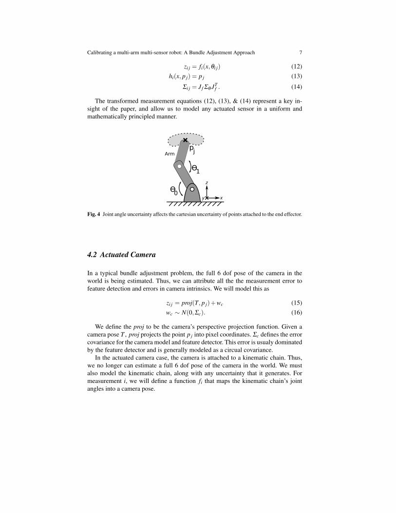
In many cases, the feature points that we are trying to calibrate against are rigidlyattached to an actuated part of the robot, such as an arm (See Fig. 4). We can thenconsider a set of joint angles θi to be our measurement. Assuming that for measure-ment i we have a forward kinematics model fi and inverse kinematics model f−1
i ,we could express our measurement model as
θi j = f−1i (x, p j)+wθ (5)
wθ ∼ N(0,Σθ ) (6)
where f−1i maps p j into joint angles based on the kinematic parameters defined in x.
The joint angle noise wθ is defined in (6) as zero-mean with a covariance of Σθ . Ingeneral, Σθ is diagonal, since joint angle uncertainty is usually independent acrossjoints.
Although (5) may seem like a convenient measurement model, it is not wellposed. For a given point, there are generally many different joint angle solutions toreach this point. So, instead of using this equation, we can map this measurementand model into cartesian space:
θi j −wθ = f−1i (x, p j) (7)
fi(x,θi j −wθ
)= fi
(x, f−1
i (x, p j))
(8)
fi(x,θi j −wθ
)= p j . (9)
After linearizing the joint angle noise and mapping it into cartesian space, (9) canbe approximated as
fi(x,θi j) = p j +wi j (10)
wi j ∼ N(0,J f Σθ JTf ) (11)
where J f is the jacobian of the forward kinematics with respect to the joint angles atθi j. We can now use (10) & (11) to represent the kinematic chain as a measurementequation:
Calibrating a multi-arm multi-sensor robot: A Bundle Adjustment Approach 7
zi j = fi(x,θi j) (12)hi(x, p j) = p j (13)
Σi j = J f Σθ JTf . (14)
The transformed measurement equations (12), (13), & (14) represent a key in-sight of the paper, and allow us to model any actuated sensor in a uniform andmathematically principled manner.
Ɵ
Ɵ
0
1
pjArm
x
z
y
Fig. 4 Joint angle uncertainty affects the cartesian uncertainty of points attached to the end effector.
4.2 Actuated Camera
In a typical bundle adjustment problem, the full 6 dof pose of the camera in theworld is being estimated. Thus, we can attribute all the the measurement error tofeature detection and errors in camera intrinsics. We will model this as
zi j = proj(T, p j)+wc (15)wc ∼ N(0,Σc). (16)
We define the proj to be the camera’s perspective projection function. Given acamera pose T , proj projects the point p j into pixel coordinates. Σc defines the errorcovariance for the camera model and feature detector. This error is usualy dominatedby the feature detector and is generally modeled as a circual covariance.
In the actuated camera case, the camera is attached to a kinematic chain. Thus,we no longer can estimate a full 6 dof pose of the camera in the world. We mustalso model the kinematic chain, along with any uncertainty that it generates. Formeasurement i, we will define a function fi that maps the kinematic chain’s jointangles into a camera pose.
8 Vijay Pradeep, Kurt Konolige & Eric Berger
zi j = proj(
fi(x,θi j +wθ ), p j)+wc (17)
wθ ∼ N(0,Σθ ). (18)
Linearizing the the error wθ gives us our measurement equation
zi j =
[uv
](19)
hi(x, p j) = proj(
fi(x,θi j), p j)
(20)
wi j = N(0,JΣθ JT +Σc) (21)
where J is the jacobian of hi with respect to θ .
Cam
Ɵ
Ɵ
0
1 pij
Arm
u
vpij
Pixel Coordinates
uw
v
w
Fig. 5 For an actuated camera, uncertainties in θ0 and θ1 influence the measurement uncertaintyof an in pixel space.
4.3 Tilting Laser Rangefinder
Most commonly used laser rangefinder sensors, such as the Sick LMS200 orHokuyo UTM-30LX, scan in a horizontal plane while providing bearing and rangemeasurements. Then, by tilting the laser up and down, we aggregate data across mul-tiple scans to generate intensity images. To robustly detect features in the laser data,we run openCV’s checkerboard detector [4] on the intensity images. Once a pointis detected in intensity image pixel coordinates, it can be reprojected into 3D usingthe tilt, bearing, and range information associated with that pixel. Fig. 7 provides anexample of an intensity image of a checkerboard.
Sensor measurement i of point p j generates a θi j that contains the tilt, bearing,and range of the sensor (see Fig 6). We can then treat the tilting laser as a kine-matic chain with two rotational joints (tilt and bearing) followed by a prismaticjoint (range). The approach from 4.1 with kinematic chains can then be used, andthe measurement equations for the tilting laser match (11)-(13):
Calibrating a multi-arm multi-sensor robot: A Bundle Adjustment Approach 9
zi j = fi(x,θi j) (11)hi(x, p j) = p j (12)
Σi j = J f Σθ JTf . (13)
pij
tilt
range
pij
x
y
zx
z
y
bearing
rangeLRF LRF
Side View Top View
Fig. 6 Side view and top view of a laser rangefinder. The shaded region around pi j shows theCartesian measurement uncertainty associated with tilt, bearing, and range measurement uncer-tainties.
Fig. 7 Intensity image of a large checkerboard generated from a tilting laser platform. The detectedcorners are marked in red.
5 Calibrating the PR2
We tested this calibration approach on the PR2 robot platform and used it to calibrate6 cameras (4 on the head and one in each forearm), a tilting laser sensor, and 16actuation degrees of freedom in two arms and a pan/tilt head (see Fig 8). Calibrationdata consists of checkerboard targets, which are visible to cameras and the laser.The pose of the checkerboard is estimated (p j in Equation 1), and the checkerboardcorners give multiple points in the nonlinear optimization.
10 Vijay Pradeep, Kurt Konolige & Eric Berger
ForearmCamera
ForearmCamera
Right Arm(7 Joints)
Left Arm(7 Joints)
Stereo Pairs(4 Cameras)
Head(2 Joints)
TiltingLaser
Fig. 8 Sensors and kinematics being calibrated on the PR2.
5.1 Choosing What To Calibrate
Effectively choosing which parameters need to calibrated can significantly improvethe quality of the calibration. Choosing too many parameters could result in over-fitting, whereas choosing too few parameters can result in unmodeled errors. Forthe PR2, we achieved good results by modeling 4 types of parameters: Joint angleoffsets, Camera poses, laser rangefinder poses, and stereocamera baselines.
Upon bootup, the PR2 moves its joints through optical interrupters, which areused to zero out the joint encoders. Although extremely repeatable, the absoluteangle at which the interrupter trips is not known. Estimating joint angle offsets letsus account for this.
To calibrate monocular camera and stereocamera intrinsics, we use ROS’s cam-era calibration package [3], which wraps OpenCV’s camera calibration routines.This intrinsic calibration estimates a principal ray of the camera, which is not nec-essarily aligned with any the mechanical axes of the camera. Thus, even, if thecamera is very accurately fixtured to the robot, its pose still needs to be estimated.The OpenCV routines do in fact estimate the stereo baseline, but this estimate canbe improved by incorporating laser rangefinder data.
With some laser rangefinders, such as the Hokuyo UTM-30LX, the location ofthe optical center and direction of the forward pointing ray are not well defined.Thus, we need to estimate the pose of the laser rangefinder.
We could potentially also estimate the kinematic link lengths and the angles be-tween joint axes. However, since all of our parts are precision machined, these pa-rameters are already well known.
Calibrating a multi-arm multi-sensor robot: A Bundle Adjustment Approach 11
5.2 Automating the data collection
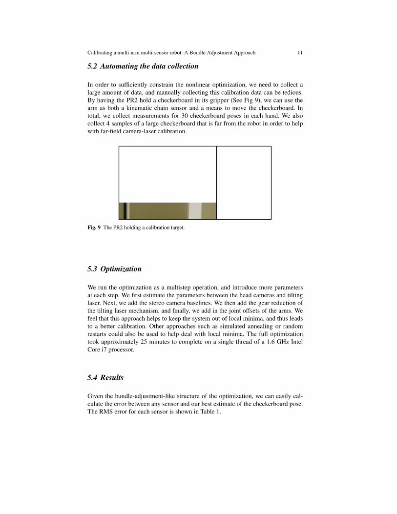
In order to sufficiently constrain the nonlinear optimization, we need to collect alarge amount of data, and manually collecting this calibration data can be tedious.By having the PR2 hold a checkerboard in its gripper (See Fig 9), we can use thearm as both a kinematic chain sensor and a means to move the checkerboard. Intotal, we collect measurements for 30 checkerboard poses in each hand. We alsocollect 4 samples of a large checkerboard that is far from the robot in order to helpwith far-field camera-laser calibration.
Fig. 9 The PR2 holding a calibration target.
5.3 Optimization
We run the optimization as a multistep operation, and introduce more parametersat each step. We first estimate the parameters between the head cameras and tiltinglaser. Next, we add the stereo camera baselines. We then add the gear reduction ofthe tilting laser mechanism, and finally, we add in the joint offsets of the arms. Wefeel that this approach helps to keep the system out of local minima, and thus leadsto a better calibration. Other approaches such as simulated annealing or randomrestarts could also be used to help deal with local minima. The full optimizationtook approximately 25 minutes to complete on a single thread of a 1.6 GHz IntelCore i7 processor.
5.4 Results
Given the bundle-adjustment-like structure of the optimization, we can easily cal-culate the error between any sensor and our best estimate of the checkerboard pose.The RMS error for each sensor is shown in Table 1.
Table 1 Individual sensor errors. Note that the forearm cameras have larger errors than the headcameras, since the head joints provide better pointing accuracy that the arm joints.
In many cases, we want to understand how much registration error there is be-tween two sensors. This is calculated by projecting point locations of one sensorinto 3D and then projecting these 3D points into a coordinate frame of another sen-sor. Figure 10a shows the pixel error from projecting tilting laser data into each ofthe head cameras. Figure 10b shows the pixel error from projecting the arm locationinto each of the head cameras. Figure 10c shows the pixel error from projecting thearm locations into the forearm cameras on the same side of the robot, as well as tothe opposite side of the robot.
5.5 Use Case: Plugging In
Insertion tasks are one class of manipulation problems that can benefit from a goodrobot calibration (See Fig 2). One example of this is the project at Willow Garageto get the PR2 to plug itself into power outlets [12]. This approach relies on a com-bination of visual differencing and mechanical search until the plug is successfullyinserted into the socket. Although almost always successful, it results in many plugin attempts that would be unnecessary with better calibration.
More recently, Willow Garage changed its approach to plugging-in and now in-corporates the calibration techniques described in this paper. In the new version, therobot relies on its forearm cameras for registration of the plug and outlet. It detectsboth the stored plug on its base and the outlet location by moving the forearm. Thecalibration of the system is sufficient for grasping the plug from the base; however,the errors described in Table 1 are too great for inserting the plug into the socket.Since the arm is always close to the same joint-space configuration during the plug-in task, we can apply a local calibration offset that accounts for the belt stretch in thearm joints and other unmodeled errors, allowing the PR2 to insert the plug into thewall in a single attempt. This type of approach would be nearly impossible withouta well-calibrated robot.
Calibrating a multi-arm multi-sensor robot: A Bundle Adjustment Approach 13
Narrow L Stereo: Right ArmNarrow R Stereo: Right ArmWide L Stereo: Right ArmWide R Stereo: Right ArmNarrow L Stereo: Left ArmNarrow R Stereo: Left ArmWide L Stereo: Left ArmWide R Stereo: Left Arm
Narrow L Stereo: Right ArmNarrow R Stereo: Right ArmWide L Stereo: Right ArmWide R Stereo: Right ArmNarrow L Stereo: Left ArmNarrow R Stereo: Left ArmWide L Stereo: Left ArmWide R Stereo: Left Arm
Before Calibration After Calibration
Pix
el E
rror
(v)
Pix
el E
rror
(v)
Pixel Error (u)Pixel Error (u)
Right Arm - Right ForearmRight Arm - Left ForearmLeft Arm - RightForearmLeft Arm - Left Forearm
Right Arm - Right ForearmRight Arm - Left ForearmLeft Arm - RightForearmLeft Arm - Left Forearm
(A)
(B)
(C)
Fig. 10 (A) Head camera to tilting laser loop error in pixels. (B) Head camera to tilting laser looperror in pixels. (C) Head camera to arm loop error in pixels. Note that the scales are different in theleft and right plots.
14 Vijay Pradeep, Kurt Konolige & Eric Berger
6 Conclusions
This work provides a flexible framework for calibrating a robot’s multiple actua-tors and its heterogeneous sensor suite. All the sensors can be incorporated into asingle optimization, because the error characteristics of each sensor are explicitlymodeled. Any new type of sensor can also be included into the optimization, solong has we have a measurement equation and error covariance to model the sen-sor. This calibration procedure has been successfully run on Willow Garage’s PR2robot, and allows the robot to perform higher precision tasks that would otherwisebe impossible without a good calibration, such as plugging into an outlet in a singleattempts.
6.1 Future Work
The calibration procedure uses manual placement of a large checkerboard, and as-sistance in gripping the small checkerboard. Ideally we would use detected featuresin the world instead of targets, to completely automate the procedure. The downsidemight be a loss in accuracy, if the world features could not be as precisely localized.Incorporating robust error measures could help to deal with this issue.
With natural features, we open the possibility of continuous auto-calibration. Oneadvantage of this technique would be continual diagnosis of the health of the robot’ssensors and mechanisms. For auto-calibration to be practical, we would need tospeed up our current implementation, which relies on Python code and numericaljacobians.
References
1. An, C.H., Atkeson, C.G., Hollerbach, J.M.: Model-based control of a robot manipulator. MITPress, Cambridge, MA, USA (1988)
2. Arun, K.S., Huang, T.S., Blostein, S.D.: Least-squares fitting of two 3-d point sets. IEEETrans. Pattern Anal. Mach. Intell. 9(5), 698–700 (1987). DOI http://dx.doi.org/10.1109/TPAMI.1987.4767965
3. Bowman, J.: Camera calibration. URL http://www.ros.org/wiki/camera_calibration
4. Bradski, G.: The OpenCV Library. Dr. Dobb’s Journal of Software Tools (2000)5. Chen, I.M., Yang, G., Tan, C.T., Yeo, S.H.: Local poe model for robot kinematic cali-
bration. Mechanism and Machine Theory 36(11-12), 1215 – 1239 (2001). DOI DOI:10.1016/S0094-114X(01)00048-9
6. Daniilidis, K.: Hand-eye calibration using dual quaternions. International Journal of RoboticsResearch 18, 286–298 (1998)
7. Hollerbach, J.M., Wampler, C.W.: The calibration index and taxonomy for robot kinematiccalibration methods. Int. J. Rob. Res. 15(6), 573–591 (1996). DOI http://dx.doi.org/10.1177/027836499601500604
Calibrating a multi-arm multi-sensor robot: A Bundle Adjustment Approach 15
8. Horaud, R., Dornaika, F.: Hand-eye calibration. Int. J. Rob. Res. 14(3), 195–210 (1995).DOI http://dx.doi.org/10.1177/027836499501400301
9. Jones, E., Oliphant, T., Peterson, P., et al.: SciPy: Open source scientific tools for Python(2001–). URL http://www.scipy.org/
10. Le, Q., Ng, A.: Joint calibration of multiple sensors. In: In Proceedings of the IEEE/RSJInternational Conference on Intelligent Robots and Systems (IROS), pp. 3651–3658 (2009)
11. Lorsakul, A., Suthakorn, J., Sinthanayothin, C.: Point-cloud-to-point-cloud technique on toolcalibration for dental implant surgical path tracking. p. 691829. SPIE (2008). DOI 10.1117/12.772257
12. Meeussen, W., Wise, M., Glaser, S., Chitta, S., McGann, C., Mihelich, P., Marder-Eppstein,E., Muja, M., Eruhimov, V., Foote, T., Hsu, J., Rusu, R.B., Marthi, B., Bradski, G., Konolige,K., Gerkey, B., Berger, E.: Autonomous door opening and plugging in with a personal robot.In: International Conference on Robotics and Automation (2010)
13. Sturm, J., Pradeep, V., Stachniss, C., Plagemann, C., Konolige, K., Burgard, W.: Learningkinematic models for articulated objects. In: Proc. of the Int. Conf. on Artificial Intelligence(IJCAI) (2009)
14. Svoboda, T., Martinec, D., Pajdla, T.: A convenient multi-camera self-calibration for virtualenvironments. PRESENCE: Teleoperators and Virtual Environments 14(4), 407–422 (2005)
15. Triggs, B., McLauchlan, P.F., Hartley, R.I., Fitzgibbon, A.W.: Bundle adjustment - a modernsynthesis. In: ICCV ’99: Proceedings of the International Workshop on Vision Algorithms,pp. 298–372. Springer-Verlag, London, UK (2000)
16. Unnikrishnan, R., Hebert, M.: Fast extrinsic calibration of a laser rangefinder to a camera.Tech. Rep. CMU-RI-TR-05-09, Robotics Institute, Pittsburgh, PA (2005)
17. Wampler, C.W., Hollerbach, J.M., Arai, T.: An implicit loop method for kinematic calibrationand its application to closed-chain mechanisms. IEEE TRANS. ROBOTICS AND AUTOMA-TION 11(5), 710–724 (1995)
18. Wyrobek, K., Berger, E., der Loos, H.V., Salisbury, K.: Towards a personal robotics develop-ment platform: Rationale and design of an intrinsically safe personal robot. In: Proc. Interna-tional Conference on Robotics and Automation (ICRA) (2008)
19. Zhang, Q.: Extrinsic calibration of a camera and laser range finder. In: In IEEE InternationalConference on Intelligent Robots and Systems (IROS), pp. 2301–2306 (2004)