23
Calibration Bench for Fast Wire Scanners: Optical Design and Issues Student Meeting 16-10-2012 Jose Luis Sirvent
| Date post: | 22-Dec-2015 |
| Category: |
Documents |
| Upload: | bertina-cross |
| View: | 216 times |
| Download: | 1 times |

Calibration Bench for Fast Wire Scanners:Optical Design and Issues
Student Meeting16-10-2012
Jose Luis Sirvent
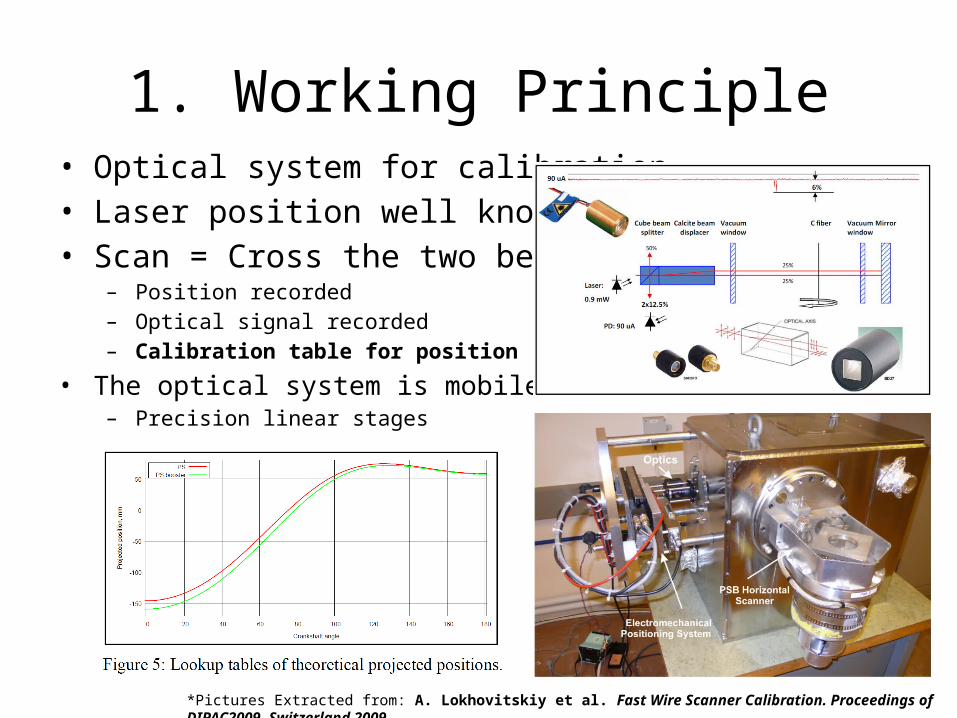
1. Working Principle• Optical system for calibration• Laser position well known• Scan = Cross the two beams
– Position recorded– Optical signal recorded– Calibration table for position
• The optical system is mobile– Precision linear stages
*Pictures Extracted from: A. Lokhovitskiy et al. Fast Wire Scanner Calibration. Proceedings of DIPAC2009, Switzerland 2009.

2. Why am I working on it?
• 1. Laser source Optical fibre (Impact??)– Rotating platform = Space limitation (The fibre is flexible)
• 2. System modeling (Zemax)
• 3. Working verification of the components already selected– MMF Fibre / 532nm Laser / PAF-X-5-A Fiber-port / Mirror / Beam
Splitter / Beam Displacer / LA1172 Lens
• 4. Proposal of new components / lens for optimization
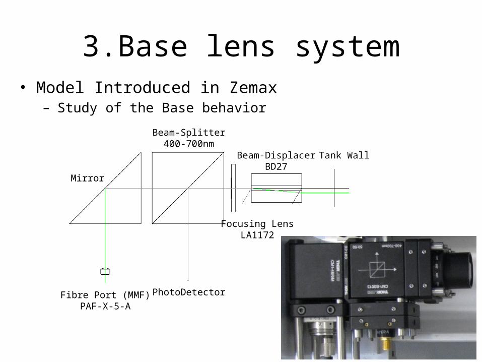
3.Base lens system• Model Introduced in Zemax
– Study of the Base behavior
Mirror
Beam-Splitter400-700nm
Beam-DisplacerBD27
Focusing LensLA1172
Tank Wall
Fibre Port (MMF)PAF-X-5-A
PhotoDetector

4. Distance issues and compromise• Linear Stage range= + - 50mm
• Horizontal Scanner crossing points– Min:225.7mm,Mean:309.4mm,Max:332.1mm
• Vertical Scanner crossing points– Min:199.mm,Mean:214.6mm,Max:240.6 mm
• Desired Specs:– Beam as small as possible (100 – 200 um)– Distance range: 199.5 – 332.1mm (132.6mm)– Focal distance: 265.8mm
*Distances with respect to the internal tank wall

5. System performance (MMF)• Smaller beam size reached in focal point?
– Fiber Core: 100 um– F1:4.5mm F2~300mm (Magnification ~ 70)– Focused Spots > 7mm (Impossible smaller with this system)– Spots Separation: 2.7mm

5. System performance (SMF)
• Gaussian optics should be considered:– Fibre MDF(532nm): 3.5nm
– Objective: Minimize 2Wo and maximize 2Zr (Compromise)• M2= Quality factor of the laser (Considered 1)• W1= Gaussian waist before focusing lens
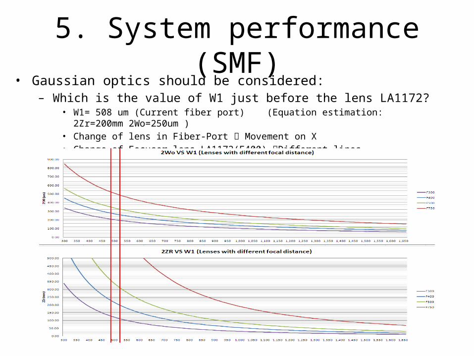
5. System performance (SMF)• Gaussian optics should be considered:
– Which is the value of W1 just before the lens LA1172?• W1= 508 um (Current fiber port) (Equation estimation: 2Zr=200mm 2Wo=250um ) • Change of lens in Fiber-Port Movement on X• Change of Focuser lens LA1172(F400) Different lines
5. System performance (SMF)
• Moving the model to Zemax 12– Protocol followed:
• The fiber port is always kept: Only adjust Fiber - 1st Lens– Simulated an aspheric lens with similar characteristics
• The assembly will be as compact as possible• 3 Focuser lens tested
– Thorlabs LA1884 (Focal 300mm)– Thorlabs LA1172 (Focal 400mm)– Thorlabs LA1464 (Focal 1000mm)
• 2 Sources tested– Current Laser 532nm (Green) + SMF MFD 3.5um– Laser LP405-SF10 405nm (Blue) + SMF MFD 2.9um
• Decision Parameters: Wo & ZR

5. System performance (SMF)
• Model appearanceFocal point
Scanners Crossing Points
Mirror
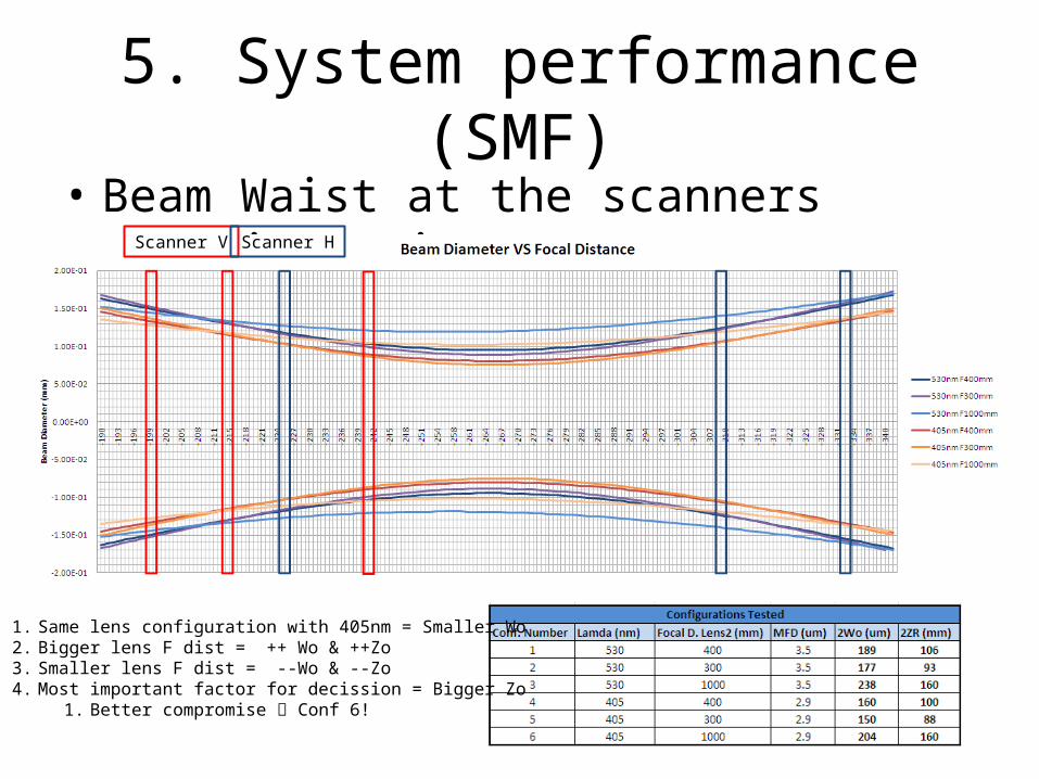
5. System performance (SMF)• Beam Waist at the scanners crossing points
Scanner V Scanner H
1. Same lens configuration with 405nm = Smaller Wo 2. Bigger lens F dist = ++ Wo & ++Zo 3. Smaller lens F dist = --Wo & --Zo4. Most important factor for decission = Bigger Zo
1. Better compromise Conf 6!

5. System performance (SMF)• Vertical and horizontal Scans Simulation
– Evolution of the light received in the scanner range (200um wire)– Comparison between two configurations (530 nm F400 & 405nm F1000)
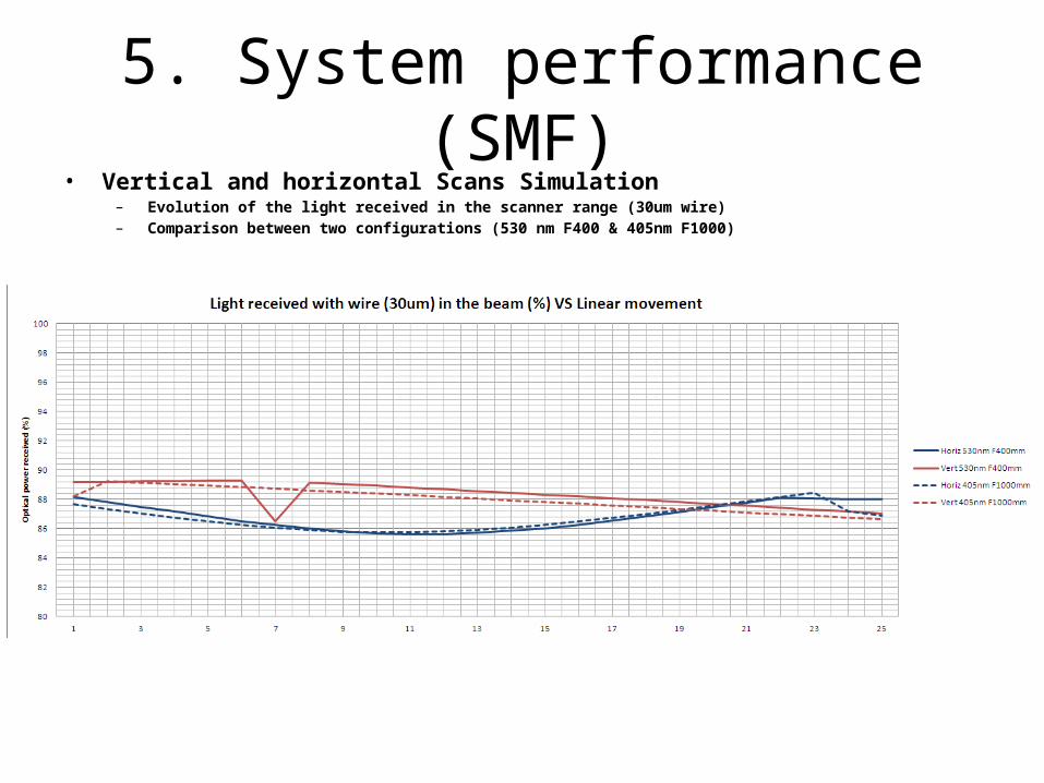
5. System performance (SMF)• Vertical and horizontal Scans Simulation
– Evolution of the light received in the scanner range (30um wire)– Comparison between two configurations (530 nm F400 & 405nm F1000)
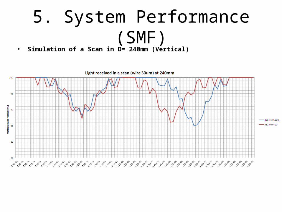
5. System Performance (SMF)• Simulation of a Scan in D= 240mm (Vertical)

6. Practical results with SMF• 1. System parameters:
– Lamda: 532nm– Lens2: F400mm– Fibre: SMF MFD 9.2um @ 1310nm (MFD @ 532nm?) This fibre is not SMF for this wavelenght.

7. Second Set of Simulations• A) 4 Different configurations will be studied and compared:
– 1. Fiber-Port + Focuser lens together (400mm)• 532nm & 405nm• D (lens Focus)= 410.71 mm
– 2. Beam displacer + Focuser lens together (300mm)• 532nm & 405nm• D (lens Focus)= 318.15 mm

7. Second Set of Simulations
• Beam Waist at the scanners crossing points

7. Second Set of Simulations• Vertical and horizontal Scans Simulation
– Evolution of the light received in the scanner range (30um wire)– Comparison between two configurations (530 nm F400 & 405nm F1000)

8. Simulations: In conclusion• 1. The most promising configurations are
– 405nm Laser, SMF (MFD 2.9um) & Focal lens LA1172 (F400mm) Around 1.5% better– 530nm Laser, SMF (MFD 3.5um) & Focal lens LA1172 (F400mm)– When wire in beam the light decreases from 100% to 75-82% (~20% )
• 2. Components to be ordered to make the system work (Thorlabs):– A) Focal lens for photodiode: LA1951 - N-BK7 Plano-Convex Lens, Ø1", f = 25.4 mm, Uncoated – B) SMF for our laser (MFD 3.5um & 530nm): P2-460A-PCSMA-1 - SM Patch Cable, 450-600 nm, FC/PC to SMA, 1 m
Optional:– C) Laser 405nm with fibre pigtail FC/PC: LP405-SF10 - 405 nm, 10 mW, B Pin Code, SM Fiber-Pigtailed Laser Diode, FC/PC

9. Practical Verification• 1. Suitable SMF fibre arrived (MFD @ 532 = 3.5um)• 2. Suitable focuser lens for photodiode arrived (LA1951 F=25.4mm)• 3. Suitable mirror also arrived (25MG00)
Scanning range
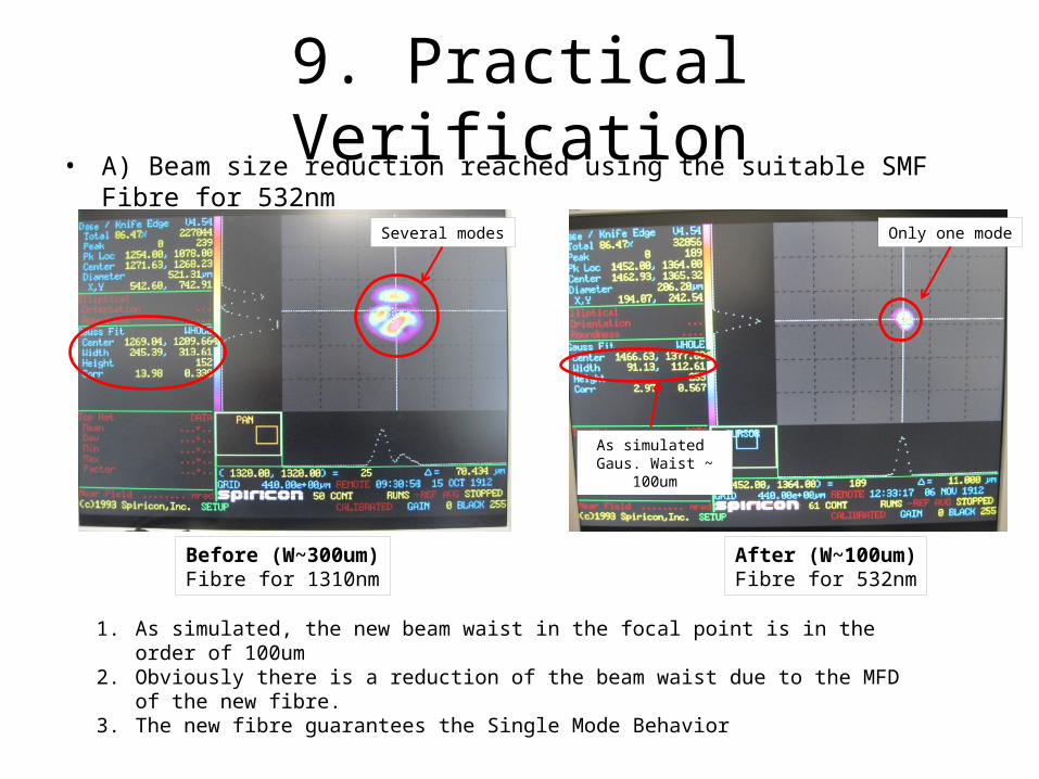
9. Practical Verification• A) Beam size reduction reached using the suitable SMF Fibre for 532nm
Before (W~300um)Fibre for 1310nm
After (W~100um)Fibre for 532nm
Several modes Only one mode
As simulated Gaus. Waist ~ 100um
1. As simulated, the new beam waist in the focal point is in the order of 100um2. Obviously there is a reduction of the beam waist due to the MFD of the new fibre.3. The new fibre guarantees the Single Mode Behavior

9. Practical Verification• B) Signal obtained when crossing the beam with two different wires
Copper wire (170um)
Carbon wire (30um)
~50% Decrease
~25% DecreaseTransimpedance Ampliffier Settings
Signal Response (Copper)Beam Diam ~ 200um --- Carbon wire 170umDecay 50% (Each beam seems to be completely covered)
Signal Response (Carbon)Beam Diam ~ 200um --- Carbon wire 30umDecay 25% (Each beam seems to be partly covered)It’s clearly visible that the beam is GaussianResults similar to the simulations!
System Settings:Offset calibrated to 0V ambient lightPhotodiode Biased (-10V)I/V Ampliffication 10e6Low Pass filter 1MHzDC Coupling
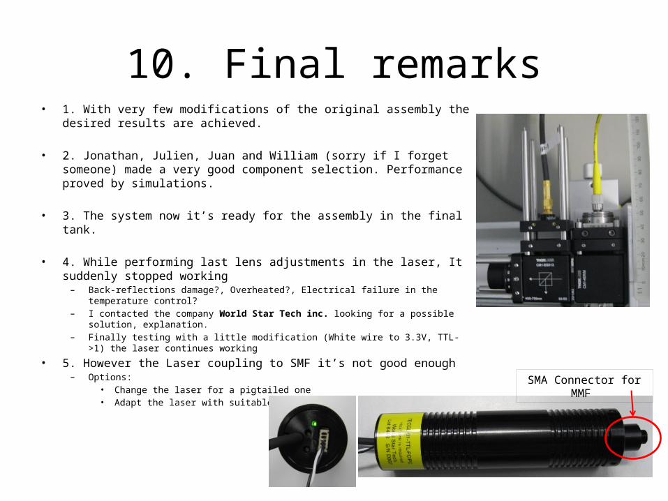
10. Final remarks• 1. With very few modifications of the original assembly the desired results
are achieved.
• 2. Jonathan, Julien, Juan and William (sorry if I forget someone) made a very good component selection. Performance proved by simulations.
• 3. The system now it’s ready for the assembly in the final tank.
• 4. While performing last lens adjustments in the laser, It suddenly stopped working– Back-reflections damage?, Overheated?, Electrical failure in the temperature control? – I contacted the company World Star Tech inc. looking for a possible solution, explanation.– Finally testing with a little modification (White wire to 3.3V, TTL->1) the laser continues
working
• 5. However the Laser coupling to SMF it’s not good enough– Options:
• Change the laser for a pigtailed one• Adapt the laser with suitable components SMA Connector for MMF


