17
Yellow: Your Tasks T1 – T4 Calibration of Button Type Beam Position Monitors
Yellow: Your Tasks T1 – T4
Calibration ofButton Type Beam Position Monitors

Simulation

Linéarité X - Y
-20
-16
-12
-8
-4
0
4
8
12
16
20
-20 -16 -12 -8 -4 0 4 8 12 16 20
X [mm]
Y [
mm
]
Position Linéarisée sur les Axes X et Y
-20
-16
-12
-8
-4
0
4
8
12
16
20
-20 -16 -12 -8 -4 0 4 8 12 16 20
X [mm]
Y [
mm
]
Position Linéarisée
-20
-16
-12
-8
-4
0
4
8
12
16
20
-20 -16 -12 -8 -4 0 4 8 12 16 20
X [mm]
Y [
mm
]
Electrostatic Pick-up – ButtonNon-linear
– requires correction algorithm when beam is off-centre
– vacuum chamber not rotational symmetric (SR-source)
Area A
r
411
521
31
61
31
551
5 1053.11053.7035.11070.31030.2 YXYXXXXX
Rhodri Jones –CERN Beam Instrumentation Group
courtesy: A.Delfs (DESY)
beam
pump
channel button pickup
(cut)
PETRA-III BPM close to ID
-10 -8 -6 -4 -2 0 2 4 6 8 10-10
-8
-6
-4
-2
0
2
4
6
8
10
Horizontal Position [mm]
Ver
tica
l P
osi
tio
n [
mm
]
Position Map
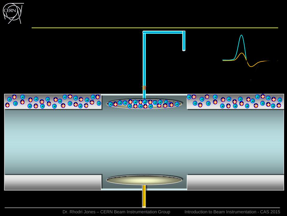
Dr. Rhodri Jones – CERN Beam Instrumentation Group Introduction to Beam Instrumentation - CAS 2015
-- - - -+
+ + ++-
++
+- -+ -+
+
-- +
-- ++- + -
-- - - - -+ +
++- +
+ +- -+
-++- -+ -+ -
- -- - - -+
+ ++-
++
+- -+ -+
+
-- +
-- ++-+-
V
- - - - - - -
-+
+ ++
+-
-+ -
+ - +- + -
- - -+ ++
- ++ -+ - -+ -+
- -- - -
++ + -
++
--+-
-
-
-
-
-
-
Electrostatic Beam Position Monitor
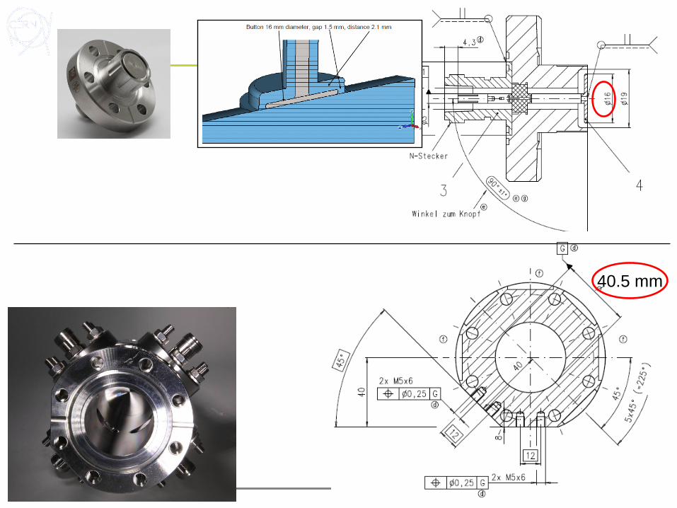
40.5 mm
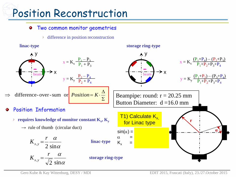
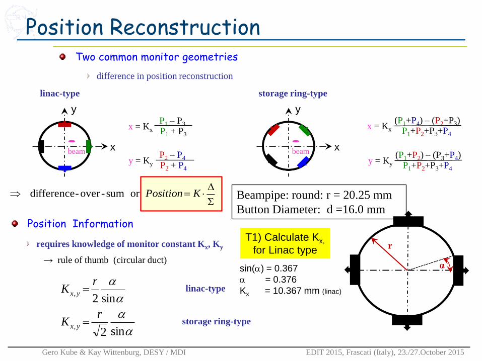
Position ReconstructionTwo common monitor geometries
Gero Kube & Kay Wittenburg, DESY / MDI EDIT 2015, Frascati (Italy), 23./27.October 2015
x
y
beam
linac-type
x = Kx
P1 – P3
P1 + P3
y = Ky
P2 – P4
P2 + P4
storage ring-type
x = Kx
(P1+P4) – (P2+P3)P1+P2+P3+P4
y = Ky
(P1+P2) – (P3+P4)P1+P2+P3+P4
x
y
beam
difference in position reconstruction
requires knowledge of monitor constant Kx, Ky
Position Information
r
α→ rule of thumb (circular duct)
sin2
sin2
,
,
rK
rK
yx
yx
linac-type
storage ring-type
KPositionor sum-over-difference Beampipe: round: r = 20.25 mm
Button Diameter: d =16.0 mm
sin() =
=
Kx =
T1) Calculate Kx,
for Linac type
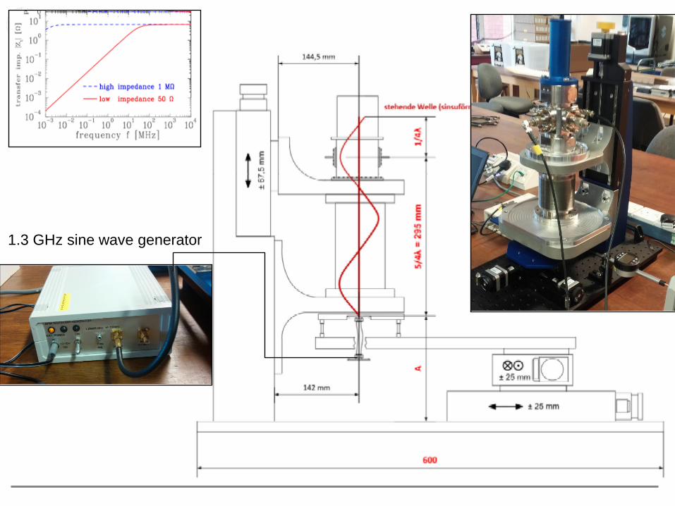
1.3 GHz sine wave generator
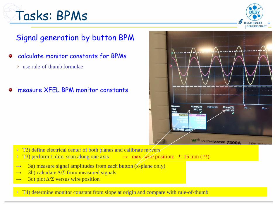
Tasks: BPMs
Signal generation by button BPM
calculate monitor constants for BPMs
use rule-of-thumb formulae
measure XFEL BPM monitor constants
T2) define electrical center of both planes and calibrate movers
T3) perform 1-dim. scan along one axis → max. wire position: ± 15 mm (!!!)
→ 3a) measure signal amplitudes from each button (x-plane only)
→ 3b) calculate Δ/Σ from measured signals
→ 3c) plot Δ/Σ versus wire position
T4) determine monitor constant from slope at origin and compare with rule-of-thumb

Monitor Constant Calculation
-20 -15 -10 -5 0 5 10 15 20-1
-0.8
-0.6
-0.4
-0.2
0
0.2
0.4
0.6
0.8
1
Beam Displacement [mm]
/
Sensitivity
sensitivity Sx,y
sensitivity: slope at origin
monitor constant: Kx,y = Sx,y-1
= Kx * /
Please stay in
the middle of
Chamber!!!!-
Maximum
± 15 mm
(more might
damage the
antenna)

• End
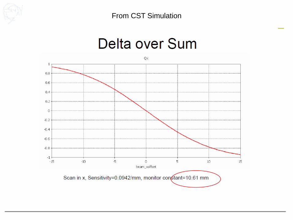
From CST Simulation
Position ReconstructionTwo common monitor geometries
Gero Kube & Kay Wittenburg, DESY / MDI EDIT 2015, Frascati (Italy), 23./27.October 2015
x
y
beam
linac-type
x = Kx
P1 – P3
P1 + P3
y = Ky
P2 – P4
P2 + P4
storage ring-type
x = Kx
(P1+P4) – (P2+P3)P1+P2+P3+P4
y = Ky
(P1+P2) – (P3+P4)P1+P2+P3+P4
x
y
beam
difference in position reconstruction
requires knowledge of monitor constant Kx, Ky
Position Information
r
α→ rule of thumb (circular duct)
sin2
sin2
,
,
rK
rK
yx
yx
linac-type
storage ring-type
KPositionor sum-over-difference Beampipe: round: r = 20.25 mm
Button Diameter: d =16.0 mm
sin() = 0.367
= 0.376
Kx = 10.367 mm (linac)
T1) Calculate Kx,
for Linac type
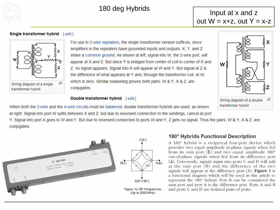
Input at x and z
out W = x+z, out Y = x-z
180 deg Hybrids
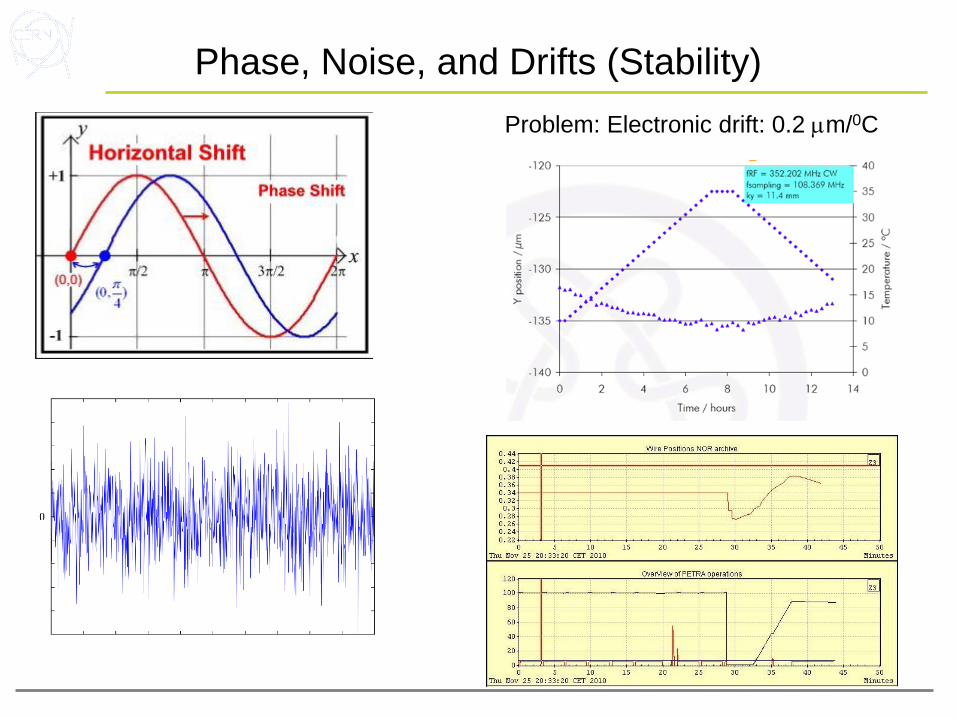
Phase, Noise, and Drifts (Stability)
Problem: Electronic drift: 0.2 mm/0C

Sensitivity

Simulation

-100% to 100% means the ± radius => x=10 => x= 40.5 mm
Kx = 1/S = 4.05 / 0.40 = 10.15
y=S*x, xfull scale = position variation, S=y/x
Multiply to the Scale a factor 2!
=0.4


![Countersink Depth Gage Calibration Instructions - Trulok · Depth Gage Calibration Instructions Indicator model: 543-342BTL . Turn the indicator on by pressing the [ON/OFF] button.](https://static.documents.pub/doc/80x56/5ce1542c88c993700d8c1c78/countersink-depth-gage-calibration-instructions-depth-gage-calibration-instructions.jpg)


