CALIBRATION PROCEDURE E³Point PROCÉDURE D’ÉTALONNAGE E³Point Set Zero Menu Only use the Set Zero function when the unit no longer displays zero. See Periodic Inspection and Maintenance . This option allows users to set the sensor Zero. In the main Set Zero screen, press enter to begin. If there is a remote sensor connected, you must scroll to select Z1 (built-in sensor) or Z2 (remote sensor). * Menu* Set Zero Set Zero Z1 Before starting the calibration, connect the regulator to the appropriate cylinder (nitrogen for all sensors except combustible, which uses air). Adjust the flow rate to the indicated rate. Connect the tubing from the regulator to the sensor calibration cap as shown in Figure 10 . Let the gas flow for at least 3 minutes before starting calibration. The next screen requests confirmation. Use the arrow keys to display Yes and press enter to confirm. Set Zero Yes A confirmation screen briefly displays and the zero calibration begins. A success or failure message displays and the screen returns to the main menu option. Figure 10. Calibration Installation Page 1 of 4
Only use the Set Zero function when the unit no longer displays zero. See Periodic Inspection and Maintenance.
This option allows users to set the sensor Zero. In the main Set Zero screen, press enter to begin. If there is a remote sensor connected, you must scroll to select Z1 (built-in sensor) or Z2 (remote sensor).
* Menu* Set Zero
Set Zero Z1
Before starting the calibration, connect the regulator to the appropriate cylinder (nitrogen for all sensors except combustible, which uses air).
Adjust the flow rate to the indicated rate.
Connect the tubing from the regulator to the sensor calibration cap as shown in Figure 10.
Let the gas flow for at least 3 minutes before starting calibration.
The next screen requests confirmation. Use the arrow keys to display Yes and press enter to confirm.
Set Zero Yes
A confirmation screen briefly displays and the zero calibration begins.
A success or failure message displays and the screen returns to the main menu option.
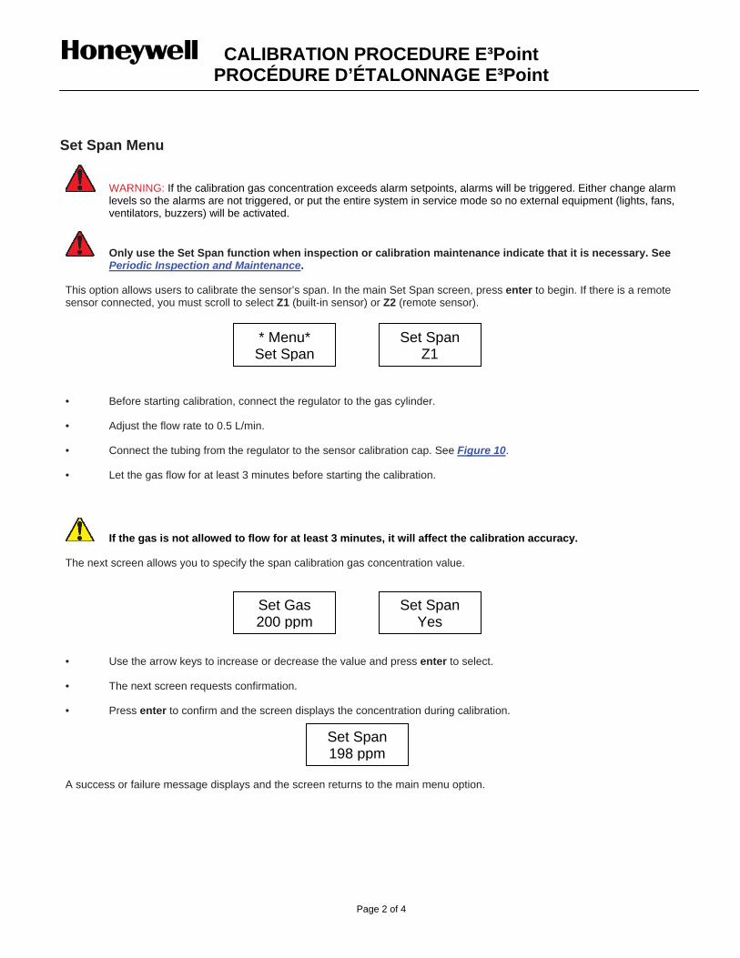
WARNING: If the calibration gas concentration exceeds alarm setpoints, alarms will be triggered. Either change alarm levels so the alarms are not triggered, or put the entire system in service mode so no external equipment (lights, fans, ventilators, buzzers) will be activated.
Only use the Set Span function when inspection or calibration maintenance indicate that it is necessary. See Periodic Inspection and Maintenance.
This option allows users to calibrate the sensor’s span. In the main Set Span screen, press enter to begin. If there is a remote sensor connected, you must scroll to select Z1 (built-in sensor) or Z2 (remote sensor).
* Menu* Set Span
Set Span Z1
• Before starting calibration, connect the regulator to the gas cylinder.
• Adjust the flow rate to 0.5 L/min.
• Connect the tubing from the regulator to the sensor calibration cap. See Figure 10.
• Let the gas flow for at least 3 minutes before starting the calibration.
If the gas is not allowed to flow for at least 3 minutes, it will affect the calibration accuracy.
The next screen allows you to specify the span calibration gas concentration value.
Set Gas 200 ppm
Set Span Yes
• Use the arrow keys to increase or decrease the value and press enter to select.
• The next screen requests confirmation.
• Press enter to confirm and the screen displays the concentration during calibration.
Set Span 198 ppm
A success or failure message displays and the screen returns to the main menu option.
Seulement utiliser la fonction Cal Zero lorsque l’unité n’affiche plus zéro.
Voir la section Inspection et entretien régulier.
Cette option permet d’ajuster le zéro de la sonde. Appuyer sur la touche entrée depuis l’écran Cal Zero pour accéder au menu : si une sonde à distance est connectée, il est nécessaire de sélectionner Z1 (sonde intégrée) ou Z2 (sonde à distance).
*Menu* Cal Zero
Cal Zero Z1
• Connecter le régulateur au cylindre approprié avant de commencer l’ajustement.
• Ajuster le débit selon les indications.
• Connecter le tuyau du régulateur au port d’étalonnage de l’unité. Voir l’illustration 10.
• Ouvrir le régulateur puis laisser le gaz circuler pendant 3 minutes avant de démarrer l’ajustement.
• L’écran suivant demande une confirmation; utiliser les touches de flèches pour afficher Oui puis appuyer sur la touche entrée pour confirmer.
Cal Zero
Qui
Un écran de confirmation est affiché brièvement, puis l’ajustement démarre.
Un message de succès ou d’échec est affiché puis l’écran retourne au menu principal.
ATTENTION. Si la concentration du gaz d’étalonnage excède les points de consigne d’alarme, des alarmes seront déclenchées. Soit changer les niveaux d’alarmes pour assurer qu’aucune alarme n’est déclenchée ou mettre le système entier en mode Service pour éviter d’activer des équipements externes (lumières, ventilateurs, avertisseurs).
Seulement utiliser l’option Etalon. (étalonnage) lorsque l’inspection ou l’entretien d’étalonnage l’indique.
Voir la section Inspection et entretien régulier.
Cette option permet d’étalonner le gain de la sonde. Appuyer sur la touche entrée depuis l’écran Etalon. pour accéder au menu : si une sonde à distance est connectée, il est nécessaire de sélectionner Z1 (sonde intégrée) ou Z2 (sonde à distance).
*Menu* Etalon
Etalon Z1
• Avant de démarrer l’étalonnage, connecter le régulateur au cylindre approprié avant de commencer l’ajustement.
• Ajuster le débit à 0.5L/min.
• Connecter le tuyau du régulateur au port d’étalonnage de l’unité (voir l’illustration 10).
• Ouvrir le régulateur puis laisser le gaz circuler pendant 3 minutes avant de démarrer l’ajustement.
À défaut de laisser circuler le gaz pendant au moins 3 minutes, il y aura un impact sur l’exactitude de l’étalonnage.
L’écran suivant permet de préciser la concentration du gaz d’étalonnage.
• Utiliser les touches de flèches pour augmenter ou diminuer la valeur puis appuyer sur la touche entrée pour sélectionner.
Etalon 200 ppm
• L’écran suivant demande une confirmation
Etalon Qui
• Appuyer sur la touche entrée pour confirmer.L’écran affiche la concentration au long de l’étalonnage.
Etalon 198 ppm
Un message de succès ou d’échec est affichée puis l’affichage retourne au menu principal.
Turn the unit on for a minimum of five (5) minutes when battery back-up sensor board is included. Check Calibration Information table (Table I) for specific warm-up time.
22.. CCOONNNNEECCTTIINNGG TTHHEE HHAARRDDWWAARREE
Plug the voltmeter probes in the unit and adjust it to read Vdc. Plug the calibration adaptor into the gas sensor inlet. Screw the regulator to the calibration span gas cylinder. Connect the regulator outlet to the calibration adaptor with the 1/8 I.D. polymer tubing.
If you suspect the presence of the target gas, inject zero gas at the specified flow rate for a minimum of 1 minute prior to adjusting the potentiometer. Adjust the zero potentiometer to read -35 mV. This must be achieved in a well ventilated area where there is no presence of the target gas. CAUTION : For all refrigerant detectors bought after April 25, 2005, do the following steps: Adjust the zero potentiometer to read 10 mV. Very slowly, adjust the zero potentiometer to read 0 mV. Be careful do not go under 0 mV because the negative voltage won’t be displayed.
44.. AADDJJUUSSTTIINNGG TTHHEE SSPPAANN
Turn on the regulator and inject span gas at the specified flow rate. The span gas is now flowing into the unit. After 2.5 minutes, the voltmeter readings should be stabilized. Then adjust the span potentiometer to read the following value:
Span Gas Value x Factor x 2.5 = Calibration value (in VDC) (+/- 3 % of the scale) Full scale
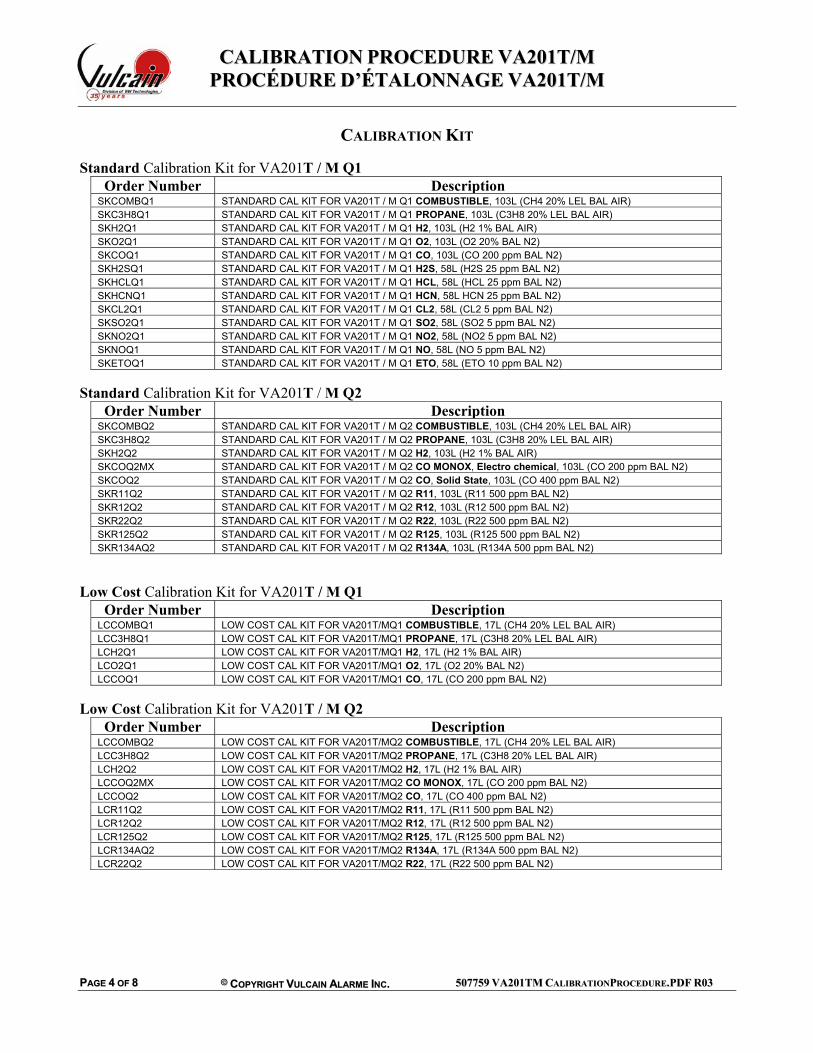
CALIBRATION KIT Standard Calibration Kit for VA201T / M Q1
Order Number DescriptionSKCOMBQ1 STANDARD CAL KIT FOR VA201T / M Q1 COMBUSTIBLE, 103L (CH4 20% LEL BAL AIR) SKC3H8Q1 STANDARD CAL KIT FOR VA201T / M Q1 PROPANE, 103L (C3H8 20% LEL BAL AIR) SKH2Q1 STANDARD CAL KIT FOR VA201T / M Q1 H2, 103L (H2 1% BAL AIR) SKO2Q1 STANDARD CAL KIT FOR VA201T / M Q1 O2, 103L (O2 20% BAL N2) SKCOQ1 STANDARD CAL KIT FOR VA201T / M Q1 CO, 103L (CO 200 ppm BAL N2) SKH2SQ1 STANDARD CAL KIT FOR VA201T / M Q1 H2S, 58L (H2S 25 ppm BAL N2) SKHCLQ1 STANDARD CAL KIT FOR VA201T / M Q1 HCL, 58L (HCL 25 ppm BAL N2) SKHCNQ1 STANDARD CAL KIT FOR VA201T / M Q1 HCN, 58L HCN 25 ppm BAL N2) SKCL2Q1 STANDARD CAL KIT FOR VA201T / M Q1 CL2, 58L (CL2 5 ppm BAL N2) SKSO2Q1 STANDARD CAL KIT FOR VA201T / M Q1 SO2, 58L (SO2 5 ppm BAL N2) SKNO2Q1 STANDARD CAL KIT FOR VA201T / M Q1 NO2, 58L (NO2 5 ppm BAL N2) SKNOQ1 STANDARD CAL KIT FOR VA201T / M Q1 NO, 58L (NO 5 ppm BAL N2) SKETOQ1 STANDARD CAL KIT FOR VA201T / M Q1 ETO, 58L (ETO 10 ppm BAL N2)
Standard Calibration Kit for VA201T / M Q2
Order Number DescriptionSKCOMBQ2 STANDARD CAL KIT FOR VA201T / M Q2 COMBUSTIBLE, 103L (CH4 20% LEL BAL AIR) SKC3H8Q2 STANDARD CAL KIT FOR VA201T / M Q2 PROPANE, 103L (C3H8 20% LEL BAL AIR) SKH2Q2 STANDARD CAL KIT FOR VA201T / M Q2 H2, 103L (H2 1% BAL AIR) SKCOQ2MX STANDARD CAL KIT FOR VA201T / M Q2 CO MONOX, Electro chemical, 103L (CO 200 ppm BAL N2) SKCOQ2 STANDARD CAL KIT FOR VA201T / M Q2 CO, Solid State, 103L (CO 400 ppm BAL N2) SKR11Q2 STANDARD CAL KIT FOR VA201T / M Q2 R11, 103L (R11 500 ppm BAL N2) SKR12Q2 STANDARD CAL KIT FOR VA201T / M Q2 R12, 103L (R12 500 ppm BAL N2) SKR22Q2 STANDARD CAL KIT FOR VA201T / M Q2 R22, 103L (R22 500 ppm BAL N2) SKR125Q2 STANDARD CAL KIT FOR VA201T / M Q2 R125, 103L (R125 500 ppm BAL N2) SKR134AQ2 STANDARD CAL KIT FOR VA201T / M Q2 R134A, 103L (R134A 500 ppm BAL N2)
Low Cost Calibration Kit for VA201T / M Q1
Order Number DescriptionLCCOMBQ1 LOW COST CAL KIT FOR VA201T/MQ1 COMBUSTIBLE, 17L (CH4 20% LEL BAL AIR) LCC3H8Q1 LOW COST CAL KIT FOR VA201T/MQ1 PROPANE, 17L (C3H8 20% LEL BAL AIR) LCH2Q1 LOW COST CAL KIT FOR VA201T/MQ1 H2, 17L (H2 1% BAL AIR) LCO2Q1 LOW COST CAL KIT FOR VA201T/MQ1 O2, 17L (O2 20% BAL N2) LCCOQ1 LOW COST CAL KIT FOR VA201T/MQ1 CO, 17L (CO 200 ppm BAL N2)
Low Cost Calibration Kit for VA201T / M Q2
Order Number DescriptionLCCOMBQ2 LOW COST CAL KIT FOR VA201T/MQ2 COMBUSTIBLE, 17L (CH4 20% LEL BAL AIR) LCC3H8Q2 LOW COST CAL KIT FOR VA201T/MQ2 PROPANE, 17L (C3H8 20% LEL BAL AIR) LCH2Q2 LOW COST CAL KIT FOR VA201T/MQ2 H2, 17L (H2 1% BAL AIR) LCCOQ2MX LOW COST CAL KIT FOR VA201T/MQ2 CO MONOX, 17L (CO 200 ppm BAL N2) LCCOQ2 LOW COST CAL KIT FOR VA201T/MQ2 CO, 17L (CO 400 ppm BAL N2) LCR11Q2 LOW COST CAL KIT FOR VA201T/MQ2 R11, 17L (R11 500 ppm BAL N2) LCR12Q2 LOW COST CAL KIT FOR VA201T/MQ2 R12, 17L (R12 500 ppm BAL N2) LCR125Q2 LOW COST CAL KIT FOR VA201T/MQ2 R125, 17L (R125 500 ppm BAL N2) LCR134AQ2 LOW COST CAL KIT FOR VA201T/MQ2 R134A, 17L (R134A 500 ppm BAL N2) LCR22Q2 LOW COST CAL KIT FOR VA201T/MQ2 R22, 17L (R22 500 ppm BAL N2)
Alimenter l’appareil, laisser la sonde chauffer pendant la période requise (Table III). 22.. ÉÉTTAALLOONNNNAAGGEE DDUU ZZEERROO ((SSII RREEQQUUIISS))
Ajuster votre multimètre pour lire des voltages DC Ajuster le potentiomètre du zéro pour lire –35mV au multimètre. Cette étape doit être réalisée dans un environnement libre de gaz ayant un facteur de sensibilité sur la sonde. ATTENTION : Pour tous les détecteurs de réfrigérant achetés après le 25 avril 2005, suivre les étapes suivantes : Ajuster potentiomètre du zéro pour lire 10mV. Très lentement, ajuster le potentiomètre du zéro à 0mV. Attention de ne pas descendre sous 0mV car la tension négative ne s’affichera pas.
Ajuster votre multimètre pour lire des voltages DC Brancher le régulateur de débit sur le cylindre de gaz et ajuster le régulateur au débit requis (Table III). Brancher l’adaptateur d’étalonnage dans le port de calibration du transmetteur
44.. ÉÉTTAALLOONNNNAAGGEE DDUU GGAAIINN
Le gaz d’étalonnage est maintenant injecté dans la sonde. Après 2 ½ min. la lecture au multimètre devrait être stabilisée. Ajuster le potentiomètre de gain pour lire la valeur selon la formule suivante:
Gaz d’étalonnage x Facteur x 2.5 = Valeur d’étalonnage en VDC (+/- 3 % de l’échelle)
KIT D’ÉTALONNAGE Kit D’étalonnage Standard for VA201T / M Q1
Order Number DescriptionSKCOMBQ1 STANDARD CAL KIT FOR VA201T / M Q1 COMBUSTIBLE, 103L (CH4 20% LEL BAL AIR) SKC3H8Q1 STANDARD CAL KIT FOR VA201T / M Q1 PROPANE, 103L (C3H8 20% LEL BAL AIR) SKH2Q1 STANDARD CAL KIT FOR VA201T / M Q1 H2, 103L (H2 1% BAL AIR) SKO2Q1 STANDARD CAL KIT FOR VA201T / M Q1 O2, 103L (O2 20% BAL N2) SKCOQ1 STANDARD CAL KIT FOR VA201T / M Q1 CO, 103L (CO 200 ppm BAL N2) SKH2SQ1 STANDARD CAL KIT FOR VA201T / M Q1 H2S, 58L (H2S 25 ppm BAL N2) SKHCLQ1 STANDARD CAL KIT FOR VA201T / M Q1 HCL, 58L (HCL 25 ppm BAL N2) SKHCNQ1 STANDARD CAL KIT FOR VA201T / M Q1 HCN, 58L HCN 25 ppm BAL N2) SKCL2Q1 STANDARD CAL KIT FOR VA201T / M Q1 CL2, 58L (CL2 5 ppm BAL N2) SKSO2Q1 STANDARD CAL KIT FOR VA201T / M Q1 SO2, 58L (SO2 5 ppm BAL N2) SKNO2Q1 STANDARD CAL KIT FOR VA201T / M Q1 NO2, 58L (NO2 5 ppm BAL N2) SKNOQ1 STANDARD CAL KIT FOR VA201T / M Q1 NO, 58L (NO 5 ppm BAL N2) SKETOQ1 STANDARD CAL KIT FOR VA201T / M Q1 ETO, 58L (ETO 10 ppm BAL N2)
Kit D’étalonnage Standard for VA201T / M Q2
Order Number DescriptionSKCOMBQ2 STANDARD CAL KIT FOR VA201T / M Q2 COMBUSTIBLE, 103L (CH4 20% LEL BAL AIR) SKC3H8Q2 STANDARD CAL KIT FOR VA201T / M Q2 PROPANE, 103L (C3H8 20% LEL BAL AIR) SKH2Q2 STANDARD CAL KIT FOR VA201T / M Q2 H2, 103L (H2 1% BAL AIR) SKCOQ2MX STANDARD CAL KIT FOR VA201T / M Q2 CO MONOX, Electro chemical, 103L (CO 200 ppm BAL N2) SKCOQ2 STANDARD CAL KIT FOR VA201T / M Q2 CO, Solid State, 103L (CO 400 ppm BAL N2) SKR11Q2 STANDARD CAL KIT FOR VA201T / M Q2 R11, 103L (R11 500 ppm BAL N2) SKR12Q2 STANDARD CAL KIT FOR VA201T / M Q2 R12, 103L (R12 500 ppm BAL N2) SKR22Q2 STANDARD CAL KIT FOR VA201T / M Q2 R22, 103L (R22 500 ppm BAL N2) SKR125Q2 STANDARD CAL KIT FOR VA201T / M Q2 R125, 103L (R125 500 ppm BAL N2) SKR134AQ2 STANDARD CAL KIT FOR VA201T / M Q2 R134A, 103L (R134A 500 ppm BAL N2)
Kit D’étalonnage « Low Cost » for VA201T / M Q1
Order Number DescriptionLCCOMBQ1 LOW COST CAL KIT FOR VA201T/MQ1 COMBUSTIBLE, 17L (CH4 20% LEL BAL AIR) LCC3H8Q1 LOW COST CAL KIT FOR VA201T/MQ1 PROPANE, 17L (C3H8 20% LEL BAL AIR) LCH2Q1 LOW COST CAL KIT FOR VA201T/MQ1 H2, 17L (H2 1% BAL AIR) LCO2Q1 LOW COST CAL KIT FOR VA201T/MQ1 O2, 17L (O2 20% BAL N2) LCCOQ1 LOW COST CAL KIT FOR VA201T/MQ1 CO, 17L (CO 200 ppm BAL N2)
Kit D’étalonnage « Low Cost » for VA201T / M Q2
Order Number DescriptionLCCOMBQ2 LOW COST CAL KIT FOR VA201T/MQ2 COMBUSTIBLE, 17L (CH4 20% LEL BAL AIR) LCC3H8Q2 LOW COST CAL KIT FOR VA201T/MQ2 PROPANE, 17L (C3H8 20% LEL BAL AIR) LCH2Q2 LOW COST CAL KIT FOR VA201T/MQ2 H2, 17L (H2 1% BAL AIR) LCCOQ2MX LOW COST CAL KIT FOR VA201T/MQ2 CO MONOX, 17L (CO 200 ppm BAL N2) LCCOQ2 LOW COST CAL KIT FOR VA201T/MQ2 CO, 17L (CO 400 ppm BAL N2) LCR11Q2 LOW COST CAL KIT FOR VA201T/MQ2 R11, 17L (R11 500 ppm BAL N2) LCR12Q2 LOW COST CAL KIT FOR VA201T/MQ2 R12, 17L (R12 500 ppm BAL N2) LCR125Q2 LOW COST CAL KIT FOR VA201T/MQ2 R125, 17L (R125 500 ppm BAL N2) LCR134AQ2 LOW COST CAL KIT FOR VA201T/MQ2 R134A, 17L (R134A 500 ppm BAL N2) LCR22Q2 LOW COST CAL KIT FOR VA201T/MQ2 R22, 17L (R22 500 ppm BAL N2)
If the VA301M doesn’t have a display, remove the cover and plug in a cover with display in J3. Turn the unit on for a minimum of five (5) minutes. Check Calibration Information (Table I) for specific warm-up time.
22.. CCOONNNNEECCTTIINNGG TTHHEE HHAARRDDWWAARREE
Screw the regulator to the appropriate calibration gas cylinder. Adjust the regulator with the suitable flow rate (see Table I). Plug the calibration adaptor onto the gas sensor inlet. Connect the regulator outlet to the calibration adaptor as shown on Figure I.
This must be achieved in a well ventilated area where there is no presence of the target gas. If you suspect the presence of the target gas in the area, inject zero gas at the specified flow rate for a minimum of 2 minutes prior to doing a Set Zero. Press the Enter key, and using the Scroll key enter the VA password. Using the Scroll key select Zone 1 (built-in CO sensor) or Zone 2 (remote sensor) and press Enter. Scroll to get the Set Zero menu. Press Enter to start the zero calibration. Wait will be displayed on the screen until calibration is completed. Scroll until Back is displayed, press Enter. Scroll until Quit is displayed, press Enter to exit.
44.. AADDJJUUSSTTIINNGG TTHHEE SSPPAANN
Turn on the regulator and inject span gas at the specified flow rate. The span gas is now flowing into the unit. Wait 2 minutes before starting the Set Span calibration. Press the Enter key, and using the Scroll key enter the VA password. Using the Scroll key select Zone 1 (built-in CO sensor) or Zone 2 (remote sensor) and press Enter. Scroll to get the Set Span menu and press Enter to go in. Using the Scroll and Enter key, input the concentration of span gas that’s going to be used. Wait will be displayed on the screen until calibration is completed. Scroll until Back is displayed, press Enter. Scroll until Quit is displayed, press Enter to exit.
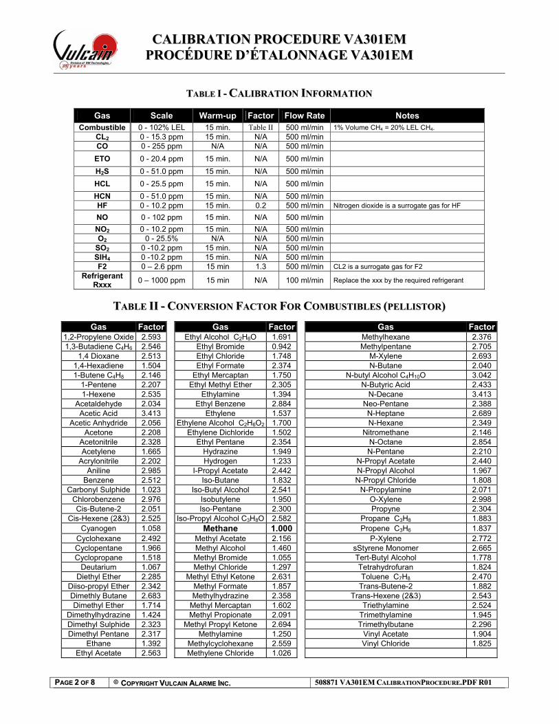
TTAABBLLEE II -- CCAALLIIBBRRAATTIIOONN IINNFFOORRMMAATTIIOONN
Gas Scale Warm-up Flow Rate Notes
CO 0 - 250 ppm 5 min. 500 ml/min NO2 0 - 10 ppm 5 min. 500 ml/min C3H8 0 - 50% LEL 15 min. 50 ml/min CH4 0 - 100% LEL 5 min 500 ml/min H2 0 – 100% LEL 5 min 500 ml/min
Figure I – Calibration equipment setup
CALIBRATION KKIITT
Order Number Description SK301MQ2CO Standard Cal Kit for VA301M CO including Display (103L CO 200 ppm BAL N2) SK301MQ2CO-NO2 Standard Cal Kit for VA301M CO-NO2 including Display
(103L CO 200 ppm BAL N2 and 58L NO2 5 ppm BAL N2) SK301MQ2CO-C3H8 Standard Cal Kit for VA301M CO-C3H8 including Display
(103L CO 200 ppm BAL N2 and 103L C3H8 20% LEL BAL AIR) SK301MQ2CO-CH4 Standard Cal Kit for VA301M CO-CH4 including Display
(103L CO 200 ppm BAL N2 and 103L CH4 1% LEL BAL AIR) SK301MQ2CO-H2 Standard Cal Kit for VA301M CO-H2 including Display
(103L CO 200 ppm BAL N2 and 103L H2 1% LEL BAL AIR)
Si le VA301M n’a pas d’afficheur, installer un couvercle avec afficheur et brancher ce dernier dans le connecteur J3. Alimenter l’appareil, laisser la sonde chauffer pendant la période requise (voir Table II).
Brancher le régulateur de débit sur le cylindre de gaz approprié. Ajuster le débit du régulateur tel qu’indiqué à la Table II. Insérer l’adaptateur d’étalonnage dans le port de calibration du transmetteur. Brancher le régulateur à l’adaptateur d’étalonnage tel qu’illustré à la Figure II.
33.. ÉTALONNAGE DU ZÉRO (SI REQUIS)
La calibration du Zéro doit se faire dans un environnement bien ventilé et exempt du gaz à détecter. Si vous soupçonner la présence de gaz cible, injecter le gaz du Zéro, au débit spécifié, pour une période de 2 minutes minimum avant de débuter l’étalonnage du Zéro. Appuyer sur le bouton Enter pour accéder au menu. Utiliser le bouton Scroll pour entrer le mot de passe VA Appuyer sur le bouton Enter pour valider le mot de passe. Utiliser le bouton Scroll pour sélectionner le menu Set Zero et la zone d’étalonnage. (Zone 1 = Sonde de CO interne, Zone 2 = Sonde à distance) Appuyer sur le bouton Enter pour lancer l’étalonnage. Le message Wait apparaît pour indique que l’étalonnage est en cours. Utiliser le bouton Scroll pour afficher le message Back et appuyer sur le bouton Enter. Utiliser le bouton Scroll pour afficher le message Quit et appuyer sur le bouton Enter pour quitter.
44.. ÉÉTTAALLOONNNNAAGGEE DDUU GGAAIINN
Ouvrir le régulateur Attendre un minimum de 2 minutes pour permettre à la lecture de se stabiliser. Appuyer sur le bouton Enter pour accéder au menu. Utiliser le bouton Scroll pour entrer le mot de passe VA Utiliser le bouton Scroll pour sélectionner le menu Set Span et la zone d’étalonnage. (Zone 1 = Sonde de CO interne, Zone 2 = Sonde à distance) Appuyer sur le bouton Enter pour valider les sélections. Utiliser le bouton Scroll pour entrer la concentration du gaz étalon et appuyer sur Enter. Le message Wait apparaît pour indique que l’étalonnage est en cours. Utiliser le bouton Scroll pour afficher le message Back et appuyer sur le bouton Enter. Utiliser le bouton Scroll pour afficher le message Quit et appuyer sur le bouton Enter pour quitter.
CO 0 - 250 ppm 5 min. 500 ml/min NO2 0 - 10 ppm 5 min. 500 ml/min C3H8 0 - 50% LEL 15 min. 50 ml/min CH4 0 - 100% LEL 5 min 500 ml/min H2 0 – 100% LEL 5 min 500 ml/min
Figure II – Configuration de l’équipement
KIT D’ÉTALONNAGE
Order Number Description SK301MQ2CO Standard Cal Kit for VA301M CO including Display (103L CO 200 ppm BAL N2) SK301MQ2CO-NO2 Standard Cal Kit for VA301M CO-NO2 including Display
(103L CO 200 ppm BAL N2 and 58L NO2 5 ppm BAL N2) SK301MQ2CO-C3H8 Standard Cal Kit for VA301M CO-C3H8 including Display
(103L CO 200 ppm BAL N2 and 103L C3H8 20% LEL BAL AIR) SK301MQ2CO-CH4 Standard Cal Kit for VA301M CO-CH4 including Display
(103L CO 200 ppm BAL N2 and 103L CH4 1% LEL BAL AIR) SK301MQ2CO-H2 Standard Cal Kit for VA301M CO-H2 including Display
(103L CO 200 ppm BAL N2 and 103L H2 1% LEL BAL AIR)
11.. WWAARRMM--UUPP PPEERRIIOODD Turn the unit on for a minimum of fifteen (15) minutes.
22.. CCOONNNNEECCTTIINNGG TTHHEE HHAARRDDWWAARREE Screw the regulator to the appropriate calibration gas cylinder.
Adjust the regulator with a flow rate of according to specification on Table I. Connect the regulator outlet to the sensor as shown on Figure I.
33.. RREEMMOOTTEE CCAALLIIBBRRAATTIINNGG TTHHEE SS330011MM SSEENNSSOORR When using the S301M in a network of sensors, connected to a VA301C controller (with firmware 3.0 or higher), it is possible to
perform a �remote calibration� using the VA301C menu:
7. Network
Statistics
Calibration
1. Using the navigation arrows, access the VA301C�s menu
2. Scroll through the menu options and select option 7. Network 3. Scroll through the Network options screens to the last screen and select the Calibration option
The Calibration screen contains four (4) lines of information:
Calib 007 S301M
Status: Normal
Set Zero
Set Span 246 PPM Line 1: Indicates the mode (Calib, meaning calibration), the (Modbus) address of the device to calibrate (007) and the type of
device to calibrate (S301M)
Line 2: Indicates the status (Normal or In calib�) of the specified device
Line 3: Displays the function to perform (Set Zero) Line 4: Displays the function to perform (Set Span) and the span gas concentration value (246 ppm)
1. On the first line, scroll to the device address and press Enter
2. Scroll through the devices to display the desired device* and press Enter to select. 3. The second line displays the device�s status
4. Scroll to select the desired function, Set Zero to set the device's zero, and press Enter to select.
Calib 007 S301M
Calibrate Zero?
Set Zero
Set Span 246 PPM 5. Upon pressing Set Zero, the controller requests confirmation. 6. Press Enter to confirm or Esc to cancel. If confirmed, the controller sets the S301M�s Zero. This takes only a few moments
and the display returns to the default calibration screen. 7. To calibrate the device, scroll to Set Span** and change the span gas calibration value using this procedure;
Calib 007 S 301 M Status : In calib ... Set Zero Set Span 246 PPM
a. Using the right arrow, move the cursor to xxx PPM (span value field). Press Enter to select the field (it�s editable when flashing).
b. Use the up or down arrows to increase or decrease the value, press Enter to validate the new value.
c. Move the cursor back to Set Span and press Enter to start the calibration.
The device Span is being calibrated. The screen will display the device�s status as �In calib...� until the calibration is complete.
*The device must be configured in the VA301C�s database in order to be included in the device addresses displayed on screen.
**When selecting Set Span, make sure that the device has been exposed to the appropriate calibration gas.
11.. PPEERRIIOODDEE DDEE RREECCHHAAUUFFFFEEMMEENNTT Alimenter l�appareil pour une période minimale de 15 minutes.
22.. BBRRAANNCCHHEERR LLEESS RREEGGUULLAATTEEUURRSS Brancher le régulateur de débit sur le cylindre de gaz approprié. Ajuster le débit du régulateur selon les spécifications de la Table II.
Relier la sortie du régulateur à la sonde tel qu�illustré à la Figure II.
33.. ÉÉTTAALLOONNNNAAGGEE ÀÀ DDIISSTTAANNCCEE DDEE LLAA SSOONNDDEE SS330011MM Lorsque le S301M est utilisé sur un réseau de sondes, connectées à la centrale VA301C (micrologiciel version 3.0 et plus), il est
possible d'effectuer un étalonnage à distance par l'entremise du menu du VA301C:
7. Reseau
Statistiques
Etalonnage
1. Utiliser les flèches de navigation pour accéder au menu du VA301C 2. Dérouler les options du menu et sélectionner l'option 7. Reseau
3. Dérouler les options de Reseau et sélectionner Etalonnage, au dernier écran
L'écran d'étalonnage contient quatre (4) lignes d'information:
Calib 007 S301M
Statut: Normale
Etal Zero
Etal Plage 246 PPM Ligne 1: Indique le mode (Calib), l'adresse de l'unité pour l'étalonnage (007) et le type d'unité à étalonner (VA301M) Ligne 2: Indique le statut (Normale ou En Etalon�) de l'unité sélectionnée
Ligne 3: Affiche la fonction à effectuer (Etal Zero)
Ligne 4: Affiche la fonction à effectuer (Etal Plage) et la concentration d'étalonnage (246 ppm)
1. Déplacer le curseur à la gauche de l'adresse de l'unité sur la première ligne et appuyer sur Enter 2. Dérouler la liste pour afficher l'adresse de l'unité désirée* puis appuyer sur Enter pour sélectionner.
3. La deuxième ligne affiche le statut de l'unité
Calib 007 S301M
Etalonner Zero?
Etal Zero
Etal Plage 246 PPM 4. Déplacer le curseur à la gauche de la fonction désirée, Etal Zero pour étalonner le zéro de l'unité, et appuyer sur Enter pour
sélectionner.
5. Lors de la sélection d'Etal Zero, la centrale demande la confirmation. 6. Appuyer sur Enter pour confirmer ou Esc pour annuler. Si confirmé, la centrale procède à l'étalonnage du zéro de l'unité. Le
processus nécessite seulement quelques instant, puis l'écran affiche de nouveau l'écran d'étalonnage. 7. Pour effectuer l'étalonnage de la plage** de l'unité, déplacer le curseur à la gauche de Etal Plage et changer la valeur
d'étalonnage avec la procédure suivante;
Calib 007 S301M
Statut : En Etalon...
Etal Zero
Etal Plage 246 PPM a. Utiliser la flèche droite pour déplacer le curseur à la gauche de to xxx PPM (champs de valeur d'étalonnage). Appuyer sur
Enter pour sélectionner le champs.
b. Utiliser les flèches haut et bas pour augmenter ou diminuer la valeur c. Déplacer le curseur à la gauche de la fonction Etal Plage et appuyer sur Enter pour valider la valeur de gaz d'étalonnage et
démarrer l'étalonnage.
L'étalonnage de la plage démarre. L'écran affiche le statut de l'unité, « En etalon... » jusqu'à la terminaison de l'étalonnage.
*L'unité doit être configurée dans la base de donnée du VA301C pour figurer dans la liste d'adresse d'unité affichée à l'écran.
**Lors de la sélection d'Etal Plage, assurer que l'unité a été exposée au gaz d'étalonnage approprié.
Turn the unit on for a minimum of fifteen (15) minutes. 2.2. CONNECTING THE HARDWAREC T HONNECTING HE ARDWARE
Screw the regulator to the appropriate calibration gas cylinder. Adjust the regulator with a flow rate of according to specification on Table I. Connect the regulator outlet to the sensor as shown on Figure I.
3.3. REMOTE CALIBRATING THE 301W SENSORR C T 301W SEMOTE ALIBRATING HE ENSOR
When using the 301W in a network of sensors, connected to a 301C controller (with firmware 3.0 or higher), it is possible to perform a “remote calibration” using the 301C menu:
1. Using the navigation arrows, access the 301C’s menu Calib 121 301W
Status : In calib...Set ZeroSet Span 246 PPM
2. Scroll through the menu options and select option 7. Network 3. Scroll through the Network options screens to the last screen and select the Calibration
option
The Calibration screen contains four (4) lines of information:
Line 1: Indicates the mode (Calib, meaning calibration), the (Modbus) address of the device to calibrate (121) and the type of device to calibrate (301W)
Line 2: Indicates the status (Normal or In calib…) of the specified device Line 3: Displays the function to perform (Set Zero) Line 4: Displays the function to perform (Set Span) and the span gas concentration value
(246 ppm) 4. On the first line, scroll to the device address and press Enter Calib 121 301W
Status: NormalSet ZeroSet Span 246 PPM
5. Scroll through the devices to display the desired device* and press Enter to select. 6. The second line displays the device’s status 7. Scroll to select the desired function, Set Zero to set the device's zero, and press Enter to
select. 8. Upon pressing Set Zero, the controller requests confirmation.
9. Press Enter to confirm or Esc to cancel. If confirmed, the controller sets the S301M’s Zero. This takes only a few moments and the display returns to the default calibration screen.
10. To calibrate the device, scroll to Set Span** and change the span gas calibration value using this procedure;
11. Using the right arrow, move the cursor to xxx PPM (span value field). Press Enter to select the field (it is editable when flashing).
Calib 121 301WStatus : In calib...Set ZeroSet Span 246 PPM
12. Use the up or down arrows to increase or decrease the value, press Enter to validate the new value.
13. Move the cursor back to Set Span and press Enter to start the calibration.
The device Span is being calibrated. The screen will display the device’s status as “In calib...” until the calibration is complete.
*The device must be configured in the 301C’s database in order to be included in the device addresses displayed on screen.
**When selecting Set Span, make sure that the device has been supplied with the appropriate calibration gas before and during the calibration process.
TTAABBLLEE II -- CCAALLIIBBRRAATTIIOONN IINNFFOORRMMAATTIIOONN Gas Scale Warm-up Flow Rate Notes CO 0 - 255 ppm 15 min. 0.5L/min No2 0 – 10.2 ppm 15 min. 1L/min O2 0 – 25.5 % Vol. 15 min. 0.5L/min
Figure I – Calibration equipment setup
CALIBRATION KIT Standard Calibration Kit (103L cylinder)
SK301WCOQ1 STANDARD CAL KIT FOR 301W CO, 103L (CO 200 ppm BAL N2) SK301WNO2Q1 STANDARD CAL KIT FOR 301W NO2, 103L (NO2 5 ppm BAL N2) SK301WO2Q1 STANDARD CAL KIT FOR 301W O2, 103L (O2 20% BAL N2)
1.1. PERIODE DE RECHAUFFEMENTPERIODE DE RECHAUFFEMENT
Alimenter l’appareil pour une période minimale de 15 minutes. 2.2. BRANCHER LES REGULATEURSBRANCHER LES REGULATEURS
Brancher le régulateur de débit sur le cylindre de gaz approprié. Ajuster le débit du régulateur selon les spécifications de la Table II. Relier la sortie du régulateur à la sonde tel qu’illustré à la Figure II.
3.3. ÉTALONNAGE À DISTANCE DE LA SONDE 301WÉ À D 301TALONNAGE ISTANCE DE LA SONDE W
Lorsque le 301W est utilisé sur un réseau de sondes, connectées à la centrale 301C (micrologiciel version 3.0 et plus), il est possible d'effectuer un étalonnage à distance par l'entremise du menu du 301C:
7. Reseau
StatistiquesEtalonnage
1. Utiliser les flèches de navigation pour accéder au menu du 301C 2. Dérouler les options du menu et sélectionner l'option 7. Reseau 3. Dérouler les options de Reseau et sélectionner Etalonnage, au dernier écran
L'écran d'étalonnage contient quatre (4) lignes d'information:
Ligne 1: Indique le mode (Calib), l'adresse de l'unité pour l'étalonnage (121) et le type
d'unité à étalonner (301W) Ligne 2: Indique le statut (Normale ou En Etalon…) de l'unité sélectionnée Ligne 3: Affiche la fonction à effectuer (Etal Zero) Ligne 4: Affiche la fonction à effectuer (Etal Plage) et la concentration d'étalonnage (246
ppm) 4. Déplacer le curseur à la gauche de l'adresse de l'unité sur la première ligne et appuyer
sur Enter Calib 121 301WStatut: NormaleEtal ZeroEtal Plage 246 PPM
5. Dérouler la liste pour afficher l'adresse de l'unité désirée* puis appuyer sur Enter pour sélectionner.
6. La deuxième ligne affiche le statut de l'unité 7. Déplacer le curseur à la gauche de la fonction désirée, Etal Zero pour étalonner le zéro de
l'unité, et appuyer sur Enter pour sélectionner. Calib 121 301WEtalonner Zero?Etal ZeroEtal Plage 246 PPM
8. Lors de la sélection d'Etal Zero, la centrale demande la confirmation. 9. Appuyer sur Enter pour confirmer ou Esc pour annuler. Si confirmé, la centrale procède
à l'étalonnage du zéro de l'unité. Le processus nécessite seulement quelques instants, puis l'écran affiche de nouveau l'écran d'étalonnage.
10. Pour effectuer l'étalonnage de la plage** de l'unité, déplacer le curseur à la gauche de Etal Plage et changer la valeur d'étalonnage avec la procédure suivante; Calib 121 301W
Statut : En Etalon...Etal ZeroEtal Plage 246 PPM
11. Utiliser la flèche droite pour déplacer le curseur à la gauche de to xxx PPM (champs de valeur d'étalonnage). Appuyer sur Enter pour sélectionner le champ.
12. Utiliser les flèches haut et bas pour augmenter ou diminuer la valeur 13. Déplacer le curseur à la gauche de la fonction Etal Plage et appuyer sur Enter pour
valider la valeur de gaz d'étalonnage et démarrer l'étalonnage.
L'étalonnage de la plage démarre. L'écran affiche le statut de l'unité, « En etalon... » jusqu'à la terminaison de l'étalonnage.
*L'unité doit être configurée dans la base de donnée du 301C pour figurer dans la liste d'adresse d'unité affichée à l'écran.
**Lors de la sélection d'Etal Plage, assurer que l'unité a été exposée au gaz d'étalonnage approprié.
TABLE II – IINNFFOORRMMAATTIIOONN DD’’ÉÉTTAALLOONNNNAAGGEE Gaz Échelle Temps de
réchauffementDébit Notes
CO 0 – 255 ppm 15 min. 0.5L/min No2 0 – 10.2 ppm 15 min. 1L/min O2 0 – 25.5 % Vol. 15 min. 0.5L/min
Figure II – Configuration de l’équipement
KIT D’ÉTALONNAGE Kit D’étalonnage Standard (Cylindre de 103L)
SK301WCOQ1 STANDARD CAL KIT FOR 301W CO, 103L (CO 200 ppm BAL N2) SK301WNO2Q1 STANDARD CAL KIT FOR 301W NO2, 103L (NO2 5 ppm BAL N2) SK301WO2Q1 STANDARD CAL KIT FOR 301W O2, 103L (O2 20% BAL N2)
11.. WWAARRMM--UUPP PPEERRIIOODD Turn the unit on for a minimum of fifteen (15) minutes. 22.. CCOONNNNEECCTTIINNGG TTHHEE HHAARRDDWWAARREE
Plug the calibration adaptor onto the gas sensor inlet. Screw the regulator to the calibration span gas cylinder or air cylinder for the zero adjustment. Connect the regulator outlet to the calibration adaptor with the 1/8” I.D. polymer tubing.
This must be achieved in a well ventilated area where there is no presence of refrigerant. If you suspect the presence of refrigerant in the area, inject air at a flow rate of 100ml/min (air gas bottle available at Vulcain 103L: #501008 or 17L: #501036), let the gas flow for 1 minute before going on.
Press Enter to get into the menu. Use the Up or Down button until the password VA is reached. Press Enter to acknowledge. Use the Up or Down arrow until the Set Zero field is reached.
Press Enter to acknowledge. Press Enter again to activate GoCalib.
Wait message appears, the transmitter will go into zero calibration. When the Menu Set Zero message appears, the zero calibration is complete. Use the Up or Down arrow until the Quit field is reached. Press Enter to exit.
44.. AADDJJUUSSTTIINNGG TTHHEE SSPPAANN
Turn on the regulator. The calibration span gas is now flowing into the unit. Let the gas flow for a minimum of 1 minute. After one minute, the reading should be stabilized. Press Enter to get into the menu. Use the Up or Down button until the password VA is reached. Press Enter to acknowledge. Use the Up or Down arrow until the Set Span field is reached. You can now set the Span gas value (in PPM) using the Up or Down button.
Press Enter to acknowledge. Press Enter again to activate GoCalib.
Wait message appears, the transmitter will go into span calibration. When the Menu Set Span message appears, the calibration is complete. Use the Up or Down arrow until the Quit field is reached. Press Enter to exit.
Turn the unit on for a minimum of fifteen (15) minutes. Check Calibration Information (Table I) for specific warm-up time.
22.. CCOONNNNEECCTTIINNGG TTHHEE HHAARRDDWWAARREE
Plug the calibration adaptor onto the gas sensor inlet. Screw the regulator to the calibration Span gas cylinder for the Span adjustment or Zero gas cylinder for the Zero adjustment and set the appropriate flow rate (Table I). Connect the regulator outlet to the calibration adaptor (Figure I & II).
When the unit indicates 0 %/ppm in an area with no presence of the target gas, proceed to step 4. To adjust the zero, inject zero gas at the specified flow rate. The zero calibration gas is now flowing into the unit. Let the gas flow for a minimum of 2.5 minutes. After 2.5 minutes, the reading should be stabilized. Press Enter to get into the menu. Use the Up or Down button until the password VA is reached. Press Enter to acknowledge. Use the Up or Down arrow until the Set Zero field is reached. Press Enter to acknowledge. Use the Up or Down arrow to select the sensor to be calibrated. Press Enter to acknowledge. Press Enter again to activate GoCalib. Wait message appears, the transmitter will go into zero calibration. The calibration procedure is finished when the Menu Set Zero message appears. Use the Up or Down arrow until the Quit field is reached. Press Enter to exit.
44.. AADDJJUUSSTTIINNGG TTHHEE SSPPAANN
Turn on the regulator. The calibration span gas is now flowing into the unit. Let the gas flow for a minimum of 2.5 minutes. After 2.5 minutes, the reading should be stabilized. Press Enter to get into the menu. Use the Up or Down button until the password VA is reached. Press Enter to acknowledge. Use the Up or Down arrow until the Set Span field is reached. Press Enter to acknowledge. Use the Up or Down arrow to select the sensor to be calibrated. Press Enter to acknowledge. Use the Up or Down button to set the span gas value multiplied by the conversion factor, if needed (see Table I & II). Press Enter to acknowledge. Press Enter again to activate GoCalib. Wait message appears, the transmitter will go into span calibration. The calibration procedure is finished when the Menu Set Span message appears. Use the Up or Down arrow until the Quit field is reached. Press Enter to exit.
Calibration Kit Standard Calibration Kit (58L or 103L cylinder) for S301D2 Sensors
Order Number Description SKCOMBEXPL STANDARD CAL KIT FOR VA201D, VA301D / D2 COMBUSTIBLE, 103L (CH4 20% LEL BAL AIR)
SKCH4EXPL2.5 STANDARD CAL KIT FOR VA201D, VA301D / D2IR COMBUSTIBLE, 103L (CH4 50% LEL BAL AIR)
SKH2EXPL STANDARD CAL KIT FOR VA201D, VA301D / D2 H2, 103L (H2 1% BAL AIR) SKO2EXPL STANDARD CAL KIT FOR VA201D, VA301D / D2 O2, 103L (O2 20% BAL N2) SKCOEXPL STANDARD CAL KIT FOR VA201D, VA301D / D2 CO, 103L (CO 200 ppm BAL N2)
SKH2SEXPL STANDARD CAL KIT FOR VA201D, VA301D / D2 H2S, 58L (H2S 25 ppm BAL N2)
SKHCLEXPL STANDARD CAL KIT FOR VA201D, VA301D / D2 HCL, 58L (HCL 25 ppm BAL N2)
SKHCNEXPL STANDARD CAL KIT FOR VA201D, VA301D / D2 HCN, 58L (HCN 25 ppm BAL N2)
SKCL2EXPL STANDARD CAL KIT FOR VA201D, VA301D / D2 CL2, 58L (CL2 5 ppm BAL N2)
SKETOEXPL STANDARD CAL KIT FOR VA201D, VA301D / D2 ETO, 58L (ETO 10 ppm BAL N2) SKSO2EXPL STANDARD CAL KIT FOR VA201D, VA301D / D2 SO2, 58L (SO2 5 ppm BAL N2)
SKNO2EXPL STANDARD CAL KIT FOR VA201D, VA301D / D2 NO2, 58L (NO2 5 ppm BAL N2)
SKCOEXPL3K STANDARD CAL KIT FOR VA201D, VA301D / D2 CO 3000 ppm, 103L (CO 3000 ppm BAL AIR)
SKNOEXPL STANDARD CAL KIT FOR VA201D, VA301D / D2 NO, 58L (NO 5 ppm BAL N2)
SKO3Q1 STANDARD CAL KIT FOR VA301D2 O3 GENERATOR
SKF2EXPL STANDARD CAL KIT FOR VA201D, VA301D / D2 F2, 58L (CL2 2 ppm BAL N2) SKSIH4EXPL STANDARD CAL KIT FOR VA201D, VA301D / D2 SIH4, 58L (SiH4 5 ppm BAL N2)
SKHFEXPL STANDARD CAL KIT FOR VA301D2 HF, 58L (NO2 5 ppm BAL N2) SKCO2EXPL10K STANDARD CAL KIT FOR VA201D, VA301D / D2 CO2 1% (10000 ppm), 103L (CO 10000 ppm BAL N2) SKCO2EXPL25K STANDARD CAL KIT FOR VA201D, VA301D / D2 CO2 2.5% (25000 ppm), 103L (CO2 25000 ppm BAL N2)
Low Cost Calibration Kit (17L cylinder) for S301D2 Sensors
Order Number Description LCCOMBEXPL LOW COST CAL KIT FOR VA201D, VA301D / D2 COMBUSTIBLE, 17L (CH4 20% LEL BAL AIR)
LCH2EXPL LOW COST CAL KIT FOR VA201D, VA301D / D2 H2, 17L (H2 1% BAL AIR)
LCO2EXPL LOW COST CAL KIT FOR VA201D, VA301D / D2 O2, 17L (O2 20% BAL N2)
LCCOEXPL LOW COST CAL KIT FOR VA201D, VA301D / D2 CO, 17L (CO 200 ppm BAL N2) Standard Calibration Kit (103L cylinder) for 301IRFS Sensors
SK301IRFR11 STANDARD CAL KIT FOR 301IRF R11, 103L (R11 500 ppm BAL N2)
SK301IRFR12 STANDARD CAL KIT FOR 301IRFR12, 103L (R12 500 ppm BAL N2)
SK301IRFR22 STANDARD CAL KIT FOR 301IRFR22, 103L (R22 500 ppm BALN2) SK301IRFR123 STANDARD CAL KIT FOR 301IRFR123, 103L (R123 500 ppm BAL N2)
SK301IRFR125 STANDARD CAL KIT FOR 301IRFR125, 103L (R125 500 ppm BAL N2)
SK301IRFR134A STANDARD CAL KIT FOR 301IRFR134A,103L (R134A 500 ppm BAL N2) Low Cost Calibration Kit (17L cylinder) 301IRFS Sensors
LC301IRFR11 LOW COST CAL KIT FOR VA301IRF R11, 17L (R11 500 ppm BAL N2)
LC301IRFR12 LOW COST CAL KIT FOR VA301IRF R12, 17L (R12 500 ppm BAL N2) LC301IRFR22 LOW COST CAL KIT FOR VA301IRF R22, 17L (R22 500 ppm BAL N2)
LC301IRFR123 LOW COST CAL KIT FOR VA301IRF R123, 17L (R123 500 ppm BAL N2)
LC301IRFR125 LOW COST CAL KIT FOR VA301IRF R125, 17L (R125 500 ppm BAL N2)
LC301IRFR134A LOW COST CAL KIT FOR VA301IRF R134A, 17L (R134A 500 ppm BAL N2)
Alimenter l’appareil, laissez les sondes chauffer pendant la période requise (voir Table III). 22.. BBRRAANNCCHHEERR LLEESS RREEGGUULLAATTEEUURRSS
Ajuster votre multimètre pour lire des voltages DC Brancher le régulateur de débit sur le cylindre de gaz et ajuster le régulateur au débit requis (voir Table III) Brancher l’adaptateur d’étalonnage dans le port de calibration du transmetteur (Figure II)
Dans un environnement libre du gaz à détecté, l’étalonnage du Zéro n’est pas requise si l’unité affiche une concentration de 0 %/ppm. Continuer à l’étape 4. Ouvrir le régulateur Attendre un minimum de 2.5 minutes pour permettre à la lecture de se stabiliser. Appuyer sur le bouton Enter pour accéder aux menus. Appuyer sur les flèches Haut ou Bas pour entrer le mot de passe VA. Appuyer sur le bouton Enter pour valider le mot de passe. Appuyer sur les flèches Haut ou Bas pour afficher le message Set Zero. Appuyer sur le bouton Enter pour valider. Appuyer sur les flèches Haut ou Bas pour sélectionner la sonde à étalonner. Appuyer sur le bouton Enter pour valider. Le message GoCalib apparaît. Appuyer sur le bouton Enter pour lancer l’étalonnage du Zéro. Le message Wait apparaît pour indiquer que l’étalonnage du Zéro est en cours. L’étalonnage est terminé lorsque le message Menu Set Zero apparaît. Appuyer sur les flèches Haut ou Bas pour afficher le message Quit. Appuyer sur le bouton Enter pour quitter.
44.. ÉÉTTAALLOONNNNAAGGEE DDUU GGAAIINN
Ouvrir le régulateur. Attendre un minimum de 2.5 minutes pour permettre à la lecture de se stabiliser. Appuyer sur le bouton Enter pour accéder aux menus. Appuyer sur les flèches Haut ou Bas pour entrer le mot de passe VA. Appuyer sur le bouton Enter pour valider le mot de passe. Appuyer sur les flèches Haut ou Bas pour afficher le message Set Span. Appuyer sur le bouton Enter pour valider. Appuyer sur les flèches Haut ou Bas pour entrer la Concentration du gaz utilisée multiplié par le Facteur de conversion, si besoin (voir Table III & IV). Appuyer sur le bouton Enter pour valider. Le message GoCalib apparaît. Appuyer sur le bouton Enter pour lancer l’étalonnage du Gain. Le message Wait apparaît pour indiquer que l’étalonnage du Gain est en cours. L’étalonnage est terminé lorsque le message Menu Set Span apparaît. Appuyer sur les flèches Haut ou Bas pour afficher le message Quit. Appuyer sur le bouton Enter pour quitter.
KIT D’ÉTALONNAGE Kit D’étalonnage Standard (Cylindre de 58L ou 103L) pour les Sondes S301D2
Order Number Description SKCOMBEXPL STANDARD CAL KIT FOR VA201D, VA301D / D2 COMBUSTIBLE, 103L (CH4 20% LEL BAL AIR)
SKCH4EXPL2.5 STANDARD CAL KIT FOR VA201D, VA301D / D2IR COMBUSTIBLE, 103L (CH4 50% LEL BAL AIR)
SKH2EXPL STANDARD CAL KIT FOR VA201D, VA301D / D2 H2, 103L (H2 1% BAL AIR)
SKO2EXPL STANDARD CAL KIT FOR VA201D, VA301D / D2 O2, 103L (O2 20% BAL N2)
SKCOEXPL STANDARD CAL KIT FOR VA201D, VA301D / D2 CO, 103L (CO 200 ppm BAL N2)
SKH2SEXPL STANDARD CAL KIT FOR VA201D, VA301D / D2 H2S, 58L (H2S 25 ppm BAL N2) SKHCLEXPL STANDARD CAL KIT FOR VA201D, VA301D / D2 HCL, 58L (HCL 25 ppm BAL N2)
SKHCNEXPL STANDARD CAL KIT FOR VA201D, VA301D / D2 HCN, 58L (HCN 25 ppm BAL N2)
SKCL2EXPL STANDARD CAL KIT FOR VA201D, VA301D / D2 CL2, 58L (CL2 5 ppm BAL N2)
SKETOEXPL STANDARD CAL KIT FOR VA201D, VA301D / D2 ETO, 58L (ETO 10 ppm BAL N2)
SKSO2EXPL STANDARD CAL KIT FOR VA201D, VA301D / D2 SO2, 58L (SO2 5 ppm BAL N2)
SKNO2EXPL STANDARD CAL KIT FOR VA201D, VA301D / D2 NO2, 58L (NO2 5 ppm BAL N2) SKCOEXPL3K STANDARD CAL KIT FOR VA201D, VA301D / D2 CO 3000 ppm, 103L (CO 3000 ppm BAL AIR) SKNOEXPL STANDARD CAL KIT FOR VA201D, VA301D / D2 NO, 58L (NO 5 ppm BAL N2)
SKO3Q1 STANDARD CAL KIT FOR VA301D2 O3 GENERATOR
SKF2EXPL STANDARD CAL KIT FOR VA201D, VA301D / D2 F2, 58L (CL2 2 ppm BAL N2)
SKSIH4EXPL STANDARD CAL KIT FOR VA201D, VA301D / D2 SIH4, 58L (SiH4 5 ppm BAL N2)
SKHFEXPL STANDARD CAL KIT FOR VA301D2 HF, 58L (NO2 5 ppm BAL N2) SKCO2EXPL10K STANDARD CAL KIT FOR VA201D, VA301D / D2 CO2 1% (10000 ppm), 103L (CO 10000 ppm BAL N2)
SKCO2EXPL25K STANDARD CAL KIT FOR VA201D, VA301D / D2 CO2 2.5% (25000 ppm), 103L (CO2 25000 ppm BAL N2) Kit D’étalonnage « Low Cost » (Cylindre 17L) pour les Sondes S301D2
Order Number Description LCCOMBEXPL LOW COST CAL KIT FOR VA201D, VA301D / D2 COMBUSTIBLE, 17L (CH4 20% LEL BAL AIR)
LCH2EXPL LOW COST CAL KIT FOR VA201D, VA301D / D2 H2, 17L (H2 1% BAL AIR) LCO2EXPL LOW COST CAL KIT FOR VA201D, VA301D / D2 O2, 17L (O2 20% BAL N2)
LCCOEXPL LOW COST CAL KIT FOR VA201D, VA301D / D2 CO, 17L (CO 200 ppm BAL N2) Kit D’étalonnage Standard (Cylindre de 103L) pour les Sondes 301IRFS
SK301IRFR11 STANDARD CAL KIT FOR 301IRF R11, 103L (R11 500 ppm BAL N2)
SK301IRFR12 STANDARD CAL KIT FOR 301IRFR12, 103L (R12 500 ppm BAL N2) SK301IRFR22 STANDARD CAL KIT FOR 301IRFR22, 103L (R22 500 ppm BALN2)
SK301IRFR123 STANDARD CAL KIT FOR 301IRFR123, 103L (R123 500 ppm BAL N2)
SK301IRFR125 STANDARD CAL KIT FOR 301IRFR125, 103L (R125 500 ppm BAL N2)
SK301IRFR134A STANDARD CAL KIT FOR 301IRFR134A,103L (R134A 500 ppm BAL N2) Kit D’étalonnage « Low Cost » (Cylindre 17L) pour les Sondes S301D2
LC301IRFR11 LOW COST CAL KIT FOR VA301IRF R11, 17L (R11 500 ppm BAL N2)
LC301IRFR12 LOW COST CAL KIT FOR VA301IRF R12, 17L (R12 500 ppm BAL N2)
LC301IRFR22 LOW COST CAL KIT FOR VA301IRF R22, 17L (R22 500 ppm BAL N2) LC301IRFR123 LOW COST CAL KIT FOR VA301IRF R123, 17L (R123 500 ppm BAL N2)
LC301IRFR125 LOW COST CAL KIT FOR VA301IRF R125, 17L (R125 500 ppm BAL N2)
LC301IRFR134A LOW COST CAL KIT FOR VA301IRF R134A, 17L (R134A 500 ppm BAL N2)
Setting the Sensor ZeroThe Sensor Zero function is represented by the LED blink code 2, and the procedure to set the sensor zero is as follows:
• Before starting the calibration (using the programming menus), connect the regulator to the gas cylinder.
• Adjust the flow rate to 0.1 L/min.• Open the rubber cap on the
IAQPoint calibration port and connect the tubing from the regulator to the sensor, as shown.
• Let the gas flow for at least 10 minutes before starting the calibration.
• Press and hold the pushbutton and count 2 blinks and release the pushbutton.
• the LED will blink the 2-blink code three times (2 blinks, pause; 2 blinks, pause; 2 blinks, pause) to request confirmation to set the sensor zero.
• Press the pushbutton and hold for one blink only once to confirm (you must confirm within 32 seconds or the screen will return to the main menu). The unit begins setting the sensor zero (throughout the zero process, the LED will blink 3 times every 4 seconds).
If the zero calibration is successful, the LED remains on without blinking.
If the calibration failed, the LED will blink non-stop.
Never calibrate the sensor Zero with ambiant air. Alwaysuse Nitrogen (N2). Make sure to release the gas to the sensor for at least 10 minutes before beginning and continue throughout.
CalibrationGas Cylinder
511703 IAQPoint User Manual 239/08 Honeywell
Using the IAQPointCalibrating the Unit
Calibrating the CO2 Sensor
The span calibration function is represented by the LED blink code 4, and the calibration procedure is as follows:
Note: When calibrating a duct mounted unit,it is best to remove the unit from its base to ensure proper calibration.
• Before starting the calibration (using the programming menus), connect the regulator to the gas cylinder.
• Adjust the flow rate to 0.1 L/min.(for the 2000 ppm range)• Connect the tubing from the regulator to the sensor, as shown in
the image at left.
• Press and hold the pushbutton and count 4 blinks and release the pushbutton.
• the LED will blink the 4-blink code three times (4 blinks, pause; 4 blinks, pause; 4 blinks, pause) to request confirmation to calibrate the span.
• Press the pushbutton once and hold for one blink only to confirm (you must confirm within 32 seconds or the screen will return to the main menu). The unit begins the calibration (throughout the calibration process, the LED will blink 5 times every 4 seconds).
If the span calibration is successful, the LED remains on without blinking.
If the calibration failed, the LED will blink non-stop.
Start exposing the sensor to the calibration gas at least 10 minutes before starting and throughout the calibration process.
22 Manuel d’utilisateur IAQPoint 511703Honeywell 9/08
Comment utiliser l’IAQPointÉtalonnage du zéro et du gain
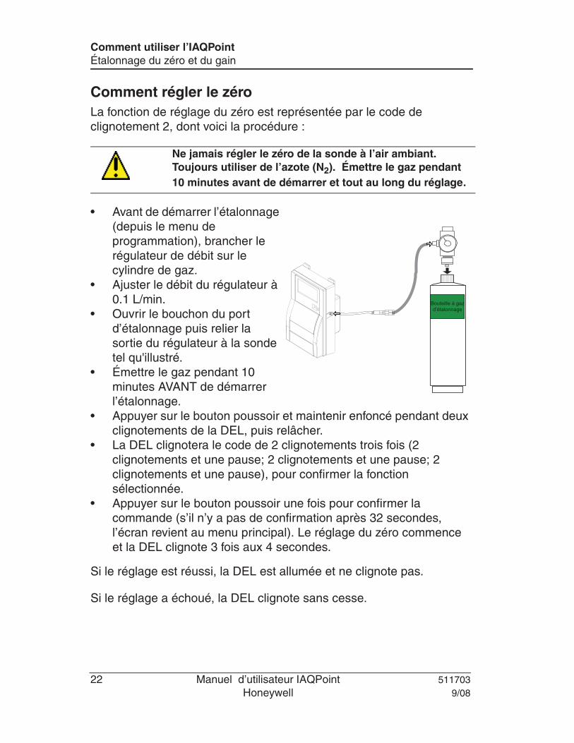
Comment régler le zéroLa fonction de réglage du zéro est représentée par le code de clignotement 2, dont voici la procédure :
• Avant de démarrer l’étalonnage (depuis le menu de programmation), brancher le régulateur de débit sur le cylindre de gaz.
• Ajuster le débit du régulateur à 0.1 L/min.
• Ouvrir le bouchon du port d’étalonnage puis relier la sortie du régulateur à la sonde tel qu'illustré.
• Émettre le gaz pendant 10 minutes AVANT de démarrer l’étalonnage.
• Appuyer sur le bouton poussoir et maintenir enfoncé pendant deux clignotements de la DEL, puis relâcher.
• La DEL clignotera le code de 2 clignotements trois fois (2 clignotements et une pause; 2 clignotements et une pause; 2 clignotements et une pause), pour confirmer la fonction sélectionnée.
• Appuyer sur le bouton poussoir une fois pour confirmer la commande (s’il n’y a pas de confirmation après 32 secondes, l’écran revient au menu principal). Le réglage du zéro commence et la DEL clignote 3 fois aux 4 secondes.
Si le réglage est réussi, la DEL est allumée et ne clignote pas.
Si le réglage a échoué, la DEL clignote sans cesse.
Ne jamais régler le zéro de la sonde à l’air ambiant. Toujours utiliser de l’azote (N2). Émettre le gaz pendant 10 minutes avant de démarrer et tout au long du réglage.
Bouteille à gaz d’étalonnage
511703 Manuel d’utilisateur IAQPoint 239/08 Honeywell
Comment utiliser l’IAQPointÉtalonnage du zéro et du gain
Comment étalonner la sonde CO2
La fonction d’étalonnage du gain est représentée par le code de clignotement 2, dont voici la procédure :
• Avant de démarrer l’étalonnage (depuis le menu de programmation), brancher le régulateur de débit sur le cylindre de gaz.
• Ajuster le débit du régulateur à 0.1 L/min (pour la plage de 2000 ppm).
• Relier la sortie du régulateur à la sonde tel qu'illustré (ci-gauche).
• Appuyer sur le bouton poussoir et maintenir enfoncé pendant deux clignotements de la DEL, puis relâcher.
• La DEL clignotera le code de 4 clignotements trois fois (4 clignotements et une pause; 4 clignotements et une pause; 4 clignotements et une pause), pour confirmer la fonction sélectionnée.
• Appuyer sur le bouton poussoir une fois pour confirmer la commande (s’il n’y a pas de confirmation après 32 secondes, l’écran revient au menu principal). Le réglage du zéro commence et la DEL clignote 3 fois toutes les 4 secondes.
Si l’étalonnage du gain est réussi, la DEL est allumée et ne clignote pas.
Si l’étalonnage du gain a échoué, la DEL clignote sans cesse.
Commencer à exposer la sonde au gaz d’étalonnage 10 minutes avant de démarrer l’étalonnage et tout au long du processus.
IAQPoint User Manual 25
Using the IAQPointProgramming Menus
Setting the Sensor ZeroThis option allows users to calibrate the sensor Zero.
• Before starting the calibration (using the programming menus), connect the regulator to the gas cylinder.
• Adjust the flow rate to 0.1 L/min.• Open the rubber cap on the
IAQPoint calibration port and connect the tubing from the regulator to the sensor, as shown.
• Let the gas flow for at least 10 minutes before starting the calibration.
• Scroll to the CO2 Set Zero screen and press Enter to select.
• The next screen requests confirmation; Use the Up or Down buttons to display YES and press Enter to confirm. (If there is no confirmation within 32 seconds, the calibration is automatically canceled and display returns to the main menu option.)
Never calibrate the sensor Zero with ambiant air. Alwaysuse Nitrogen (N2). Make sure to release the gas to the sensor for at least 10 minutes before beginning and continue throughout.
CalibrationGas Cylinder
* Menu *CO2 Set Zero
CO2 Set ZeroYES
26 IAQPoint User Manual
Using the IAQPointProgramming Menus
A confirmation screen is briefly displayed and the zero calibration begins.
A success or failure message is displayed and the screen returns to the main menu option.
Calibrating the CO2 Sensor
This option allows users to calibrate the sensor’s span.
Note: When calibrating a duct mounted unit, the unit must be removed from its base to ensure proper calibration.
• Before starting the calibration (using the programming menus), connect the regulator to the gas cylinder.
• Adjust the flow rate to 0.1 L/min.(for the 2000 ppm range)• Connect the tubing from the regulator to the sensor, as shown in the
image at left.
• Let the gas flow for at least 10 minutes before starting the calibration.• Scroll to the “CO2 Set Span” main menu option and press Enter to
select.
• The next screen allows you to specify the span calibration gas concentration value.
Start exposing the sensor to the calibration gas at least 10 minutes before starting and throughout the calibration process.
*Menu*In Calib
CO2 Set ZeroSUCCESS
* Menu *CO2 Set Span
Set Span Gas2000
IAQPoint User Manual 27
Using the IAQPointProgramming Menus
• Use the Up or Down buttons to increase or decrease the value and press Enter to select.
• The next screen requests confirmation; press Enter to confirm and the screen displays the following message. (If there is no confirmation within 32 seconds, the calibration is automatically canceled and display returns to the main menu option)
A success or failure message is displayed and the screen returns to the main menu option.
CO2 Set SpanYES
*Menu*In Calib
CO2 Set SpanSUCCESS
Manuel d’utilisateur IAQPoint 25
Comment utiliser l’IAQPointMenus de programmation
Comment régler le zéro de la sondeCette option permet de régler le zéro de la sonde.
• Avant de démarrer l’étalonnage (depuis le menu de programmation), brancher le régulateur de débit sur le cylindre de gaz.
• Ajuster le débit du régulateur à 0.1 L/min.
• Ouvrir le bouchon du port d’étalonnage puis relier la sortie du régulateur à la sonde tel qu'illustré.
• Émettre le gaz pendant 10 minutes AVANT de démarrer l’étalonnage.
• Naviguer à l’option « CO2 Set Zero » puis appuyer sur Retour pour sélectionner.
• L’écran suivant demande une confirmation; utiliser le bouton haut ou bas pour afficher YES puis appuyer sur Retour pour confirmer. (Si le système n’a pas de confirmation après 32 secondes, le réglage est annulé puis l’écran revient à l’option de menu principale.)
Un écran de confirmation est affiché brièvement et le réglage du zéro commence.
Ne jamais régler le zéro de la sonde à l’air ambiant. Toujours utiliser de l’azote (N2). Émettre le gaz pendant 10 minutes avant de démarrer et tout au long du réglage.
Bouteille à gaz d’étalonnage
* Menu *CO2 Set Zero
CO2 Set ZeroYES
*Menu*In Calib
26 Manuel d’utilisateur IAQPoint
Comment utiliser l’IAQPointMenus de programmation
Un message de réussite ou d’échec est affiché puis l’écran revient au menu principal.
Comment étalonner la sonde CO2 L’option « CO2 Set Span » permet d’étalonner le gain de la sonde.
Note: Lors de l’étalonnage d’unité monté sur conduit, l’unité doît être déconnnectée de sa base pour assurer un étalonnage exact.
• Avant de démarrer l’étalonnage (depuis le menu de programmation), brancher le régulateur de débit sur le cylindre de gaz.
• Ajuster le débit du régulateur à 0.1 L/min (pour la plage de 2000 ppm).
• Relier la sortie du régulateur à la sonde tel qu'illustré (ci-gauche).
• Émettre le gaz pendant 10 minutes AVANT de démarrer l’étalonnage.• Naviguer à l’écran « CO2 Set Span » puis appuyer sur Retour pour
sélectionner.
• L’écran suivant permet de préciser la concentration du gaz d’étalonnage.
Commencer à exposer la sonde au gaz d’étalonnage 10 minutes avant de démarrer l’étalonnage et tout au long du processus.
CO2 Set ZeroSUCCESS
* Menu *CO2 Set Span
Set Span Gas2000
Manuel d’utilisateur IAQPoint 27
Comment utiliser l’IAQPointMenus de programmation
• Utiliser les boutons haut ou bas pour augmenter ou pour diminuer la valeur puis appuyer sur Retour pour confirmer.
• L’écran suivant demande une confirmation; utiliser le bouton haut ou bas pour afficher YES puis appuyer sur Retour pour confirmer. (Si le système n’a pas de confirmation après 32 secondes, l’étalonnage est annulé puis l’écran revient à l’option de menu principale.)
• Un écran de confirmation est affiché brièvement et le réglage du zéro commence.
Un message de réussite ou d’échec est affiché puis l’écran revient au menu principal.
Turn the unit on for a minimum of fifteen (15) minutes. Check Calibration Information (Table I) for specific warm-up time.
22.. CCOONNNNEECCTTIINNGG TTHHEE HHAARRDDWWAARREE
Plug the calibration adaptor onto the gas sensor inlet. Screw the regulator to the calibration Span gas cylinder for the Span adjustment or Zero gas cylinder for the Zero adjustment and set the appropriate flow rate (Table I). Connect the regulator outlet to the calibration adaptor (Figure I)
When the unit indicates 0 %/ppm in an area with no presence of the target gas, proceed to step 4. Turn on the regulator. The calibration zero gas is now flowing into the unit. Wait for 2.5 minutes minimum to allow the reading to stabilize. Place the magnet on top of Menu. Then place it above Up or Down arrow until the password VA is reached. Place the magnet on top of Menu to acknowledge. Place the magnet on top of Up or Down arrow until the Set Zero field is reached. Place the magnet on top of Menu to acknowledge. Place the magnet on top of Menu to activate GoCalib. Wait message appears, the transmitter will go into zero calibration. The calibration procedure is finished when the Menu Set Zero message appears. Place the magnet on top of Up or Down arrow until the Quit field is reached. Place the magnet on top of Menu to confirm.
44.. AADDJJUUSSTTIINNGG TTHHEE SSPPAANN
Turn on the regulator. The calibration span gas is now flowing into the unit. Wait for 2.5 minutes minimum to allow the reading to stabilize. Place the magnet on top of Menu. Then place it above Up or Down arrow until the password VA is reached. Place the magnet on top of Menu to acknowledge. Place the magnet on top of Up or Down arrow until the Set Span field is reached. Place the magnet on top of Menu to acknowledge. Place the magnet on top of Up or Down arrow to select the proper gas value multiplied by the conversion factor, if needed (see Table I, II or III). Once the span gas value is selected, place the magnet on top of Menu to acknowledge. When GoCalib? Is displayed, place the magnet on top of Menu to start the calibration. Wait message appears, the transmitter will go into auto calibration mode. During the calibration, Set Span and gas reading are displayed The calibration procedure is finished when the Menu Set Span message appears. Place the magnet on top of Up or Down arrow until the Quit field is reached. Place the magnet on top of Menu to exit.
CALIBRATION KIT Standard Calibration Kit (58L or 103L cylinder)
Order Number Description SKCOMBEXPL STANDARD CAL KIT FOR VA201D, VA301D / D2 COMBUSTIBLE, 103L (CH4 20% LEL BAL AIR)
SKCH4EXPL2.5 STANDARD CAL KIT FOR VA201D, VA301D / D2IR COMBUSTIBLE, 103L (CH4 50% LEL BAL AIR)
SKH2EXPL STANDARD CAL KIT FOR VA201D, VA301D / D2 H2, 103L (H2 1% BAL AIR)
SKO2EXPL STANDARD CAL KIT FOR VA201D, VA301D / D2 O2, 103L (O2 20% BAL N2)
SKCOEXPL STANDARD CAL KIT FOR VA201D, VA301D / D2 CO, 103L (CO 200 ppm BAL N2)
SKH2SEXPL STANDARD CAL KIT FOR VA201D, VA301D / D2 H2S, 58L (H2S 25 ppm BAL N2) SKHCLEXPL STANDARD CAL KIT FOR VA201D, VA301D / D2 HCL, 58L (HCL 25 ppm BAL N2)
SKHCNEXPL STANDARD CAL KIT FOR VA201D, VA301D / D2 HCN, 58L (HCN 25 ppm BAL N2)
SKCL2EXPL STANDARD CAL KIT FOR VA201D, VA301D / D2 CL2, 58L (CL2 5 ppm BAL N2)
SKETOEXPL STANDARD CAL KIT FOR VA201D, VA301D / D2 ETO, 58L (ETO 10 ppm BAL N2)
SKSO2EXPL STANDARD CAL KIT FOR VA201D, VA301D / D2 SO2, 58L (SO2 5 ppm BAL N2)
SKNO2EXPL STANDARD CAL KIT FOR VA201D, VA301D / D2 NO2, 58L (NO2 5 ppm BAL N2) SKCOEXPL3K STANDARD CAL KIT FOR VA201D, VA301D / D2 CO 3000 ppm, 103L (CO 3000 ppm BAL AIR) SKNOEXPL STANDARD CAL KIT FOR VA201D, VA301D / D2 NO, 58L (NO 5 ppm BAL N2)
SKO3Q1 STANDARD CAL KIT FOR VA301D2 O3 GENERATOR
SKF2EXPL STANDARD CAL KIT FOR VA201D, VA301D / D2 F2, 58L (CL2 2 ppm BAL N2)
SKSIH4EXPL STANDARD CAL KIT FOR VA201D, VA301D / D2 SIH4, 58L (SiH4 5 ppm BAL N2)
SKHFEXPL STANDARD CAL KIT FOR VA301D2 HF, 58L (NO2 5 ppm BAL N2) SKCO2EXPL10K STANDARD CAL KIT FOR VA201D, VA301D / D2 CO2 10000 ppm, 103L (CO2 1% BAL N2)
SKCO2EXPL25K STANDARD CAL KIT FOR VA201D, VA301D / D2 CO2 30000 ppm, 103L (CO2 3% BAL N2) Low Cost Calibration Kit (17L cylinder)
Order Number Description LCCOMBEXPL LOW COST CAL KIT FOR VA201D, VA301D / D2 COMBUSTIBLE, 17L (CH4 20% LEL BAL AIR)
LCH2EXPL LOW COST CAL KIT FOR VA201D, VA301D / D2 H2, 17L (H2 1% BAL AIR)
LCO2EXPL LOW COST CAL KIT FOR VA201D, VA301D / D2 O2, 17L (O2 20% BAL N2)
LCCOEXPL LOW COST CAL KIT FOR VA201D, VA301D / D2 CO, 17L (CO 200 ppm BAL N2)
Alimenter l’appareil, laissez la sonde chauffer pendant la période requise (voir Table IV). 22.. BBRRAANNCCHHEERR LLEESS RREEGGUULLAATTEEUURRSS
Ajuster votre multimètre pour lire des voltages DC Brancher le régulateur de débit sur le cylindre de gaz et ajuster le régulateur au débit requis (voir Table IV) Brancher l’adaptateur d’étalonnage dans le port de calibration du transmetteur (Figure II)
Dans un environnement libre du gaz à détecté, l’étalonnage du Zéro n’est pas requise si l’unité affiche une concentration de 0 %/ppm. Continuer à l’étape 4. Ouvrir le régulateur Attendre un minimum de 2.5 minutes pour permettre à la lecture de se stabiliser. Placer l’aimant au dessus de Menu. Activer les flèches Haut ou Bas pour entrer le mot de passe VA. Placer l’aimant au dessus de Menu pour valider le mot de passe. Activer les flèches Haut ou Bas pour afficher le message Set Zero. Placer l’aimant au dessus de Menu pour valider. Le message GoCalib apparaît. Placer l’aimant au dessus de Menu pour lancer l’étalonnage du Zéro. Le message Wait apparaît pour indiquer que l’étalonnage du Zéro est en cours. L’étalonnage est terminé lorsque le message Menu Set Zero apparaît. Activer les flèches Haut ou Bas pour afficher le message Quit. Placer l’aimant au dessus de Menu pour quitter.
44.. ÉÉTTAALLOONNNNAAGGEE DDUU GGAAIINN
Ouvrir le régulateur Attendre un minimum de 2.5 minutes pour permettre à la lecture de se stabiliser. Placer l’aimant au dessus de Menu. Activer les flèches Haut ou Bas pour entrer le mot de passe VA. Placer l’aimant au dessus de Menu pour valider le mot de passe. Activer les flèches Haut ou Bas pour afficher le message Set Span. Placer l’aimant au dessus de Menu pour valider. Activer les flèches Haut ou Bas pour entrer la Concentration du gaz utilisée multiplié par le Facteur de conversion, si besoin (voir Table IV, V ou VI). Placer l’aimant au dessus de Menu pour valider la valeur calculée précédemment. Le message GoCalib apparaît. Placer l’aimant au dessus de Menu pour lancer l’étalonnage du Gain. Le message Wait apparaît pour indiquer que l’étalonnage du Gain est en cours. L’étalonnage est terminé lorsque le message Menu Set Span apparaît. Activer les flèches Haut ou Bas pour afficher le message Quit. Placer l’aimant au dessus de Menu pour quitter.
SO2 0 -10.2 ppm 15 min. N/A 500 ml/min SIH4 0 -10.2 ppm 15 min. N/A 500 ml/min F2 0 – 2.6 ppm 15 min 1.3 500 ml/min CL2 est utilisé en remplacement du F2
KIT D’ÉTALONNAGE Kit D’étalonnage Standard (Cylindre de 58L ou 103L)
Order Number Description SKCOMBEXPL STANDARD CAL KIT FOR VA201D, VA301D / D2 COMBUSTIBLE, 103L (CH4 20% LEL BAL AIR)
SKCH4EXPL2.5 STANDARD CAL KIT FOR VA201D, VA301D / D2IR COMBUSTIBLE, 103L (CH4 50% LEL BAL AIR)
SKH2EXPL STANDARD CAL KIT FOR VA201D, VA301D / D2 H2, 103L (H2 1% BAL AIR) SKO2EXPL STANDARD CAL KIT FOR VA201D, VA301D / D2 O2, 103L (O2 20% BAL N2) SKCOEXPL STANDARD CAL KIT FOR VA201D, VA301D / D2 CO, 103L (CO 200 ppm BAL N2)
SKH2SEXPL STANDARD CAL KIT FOR VA201D, VA301D / D2 H2S, 58L (H2S 25 ppm BAL N2) SKHCLEXPL STANDARD CAL KIT FOR VA201D, VA301D / D2 HCL, 58L (HCL 25 ppm BAL N2)
SKHCNEXPL STANDARD CAL KIT FOR VA201D, VA301D / D2 HCN, 58L (HCN 25 ppm BAL N2)
SKCL2EXPL STANDARD CAL KIT FOR VA201D, VA301D / D2 CL2, 58L (CL2 5 ppm BAL N2)
SKETOEXPL STANDARD CAL KIT FOR VA201D, VA301D / D2 ETO, 58L (ETO 10 ppm BAL N2)
SKSO2EXPL STANDARD CAL KIT FOR VA201D, VA301D / D2 SO2, 58L (SO2 5 ppm BAL N2)
SKNO2EXPL STANDARD CAL KIT FOR VA201D, VA301D / D2 NO2, 58L (NO2 5 ppm BAL N2) SKCOEXPL3K STANDARD CAL KIT FOR VA201D, VA301D / D2 CO 3000 ppm, 103L (CO 3000 ppm BAL AIR)
SKNOEXPL STANDARD CAL KIT FOR VA201D, VA301D / D2 NO, 58L (NO 5 ppm BAL N2)
SKO3Q1 STANDARD CAL KIT FOR VA301D2 O3 GENERATOR
SKF2EXPL STANDARD CAL KIT FOR VA201D, VA301D / D2 F2, 58L (CL2 2 ppm BAL N2)
SKSIH4EXPL STANDARD CAL KIT FOR VA201D, VA301D / D2 SIH4, 58L (SiH4 5 ppm BAL N2)
SKHFEXPL STANDARD CAL KIT FOR VA301D2 HF, 58L (NO2 5 ppm BAL N2) SKCO2EXPL10K STANDARD CAL KIT FOR VA201D, VA301D / D2 CO2 10000 ppm, 103L (CO2 1% BAL N2) SKCO2EXPL25K STANDARD CAL KIT FOR VA201D, VA301D / D2 CO2 30000 ppm, 103L (CO2 3% BAL N2)
Kit D’étalonnage « Low Cost » (Cylinder 17L)
Order Number Description LCCOMBEXPL LOW COST CAL KIT FOR VA201D, VA301D / D2 COMBUSTIBLE, 17L (CH4 20% LEL BAL AIR) LCH2EXPL LOW COST CAL KIT FOR VA201D, VA301D / D2 H2, 17L (H2 1% BAL AIR) LCO2EXPL LOW COST CAL KIT FOR VA201D, VA301D / D2 O2, 17L (O2 20% BAL N2)
LCCOEXPL LOW COST CAL KIT FOR VA201D, VA301D / D2 CO, 17L (CO 200 ppm BAL N2)
Make sure that the unit has completed its warm up cycle (approximately 15 minutes) before beginning the calibration. CONNECTING THE HARDWARE 1. Plug the calibration adaptor onto the gas sensor inlet. 2. Screw the regulator to the calibration zero gas cylinder and adjust the flow rate to 0.5L/min. 3. Connect the regulator outlet to the calibration adaptor as shown on Figure I. ADJUSTING THE ZERO (UNITS WITHOUT DISPLAY) 1. Turn on the regulator. 2. The nitrogen Zero gas is now flowing into the unit. 3. Let the gas flow for a minimum of 10 minutes. 4. Press the left button once and wait for the red LED to begin flashing. 5. Press the left button again to confirm the start of calibration. 6. The red LED will then blink quickly during the entire calibration process. 7. The calibration procedure is finished when the red LED blinks normally. ADJUSTING THE ZERO (UNITS WITH DISPLAY) Access to the 90DM4 programming is achieved through push buttons located on the back of the device, accessible through an oblong cut-out. The left hand button opens access to programming functions and validates selections (equivalent to an Enter button). The right hand button scrolls through main programming screens and increases values when in a specific programming screen. Hold the unit (facing you) in both hands Place both index fingers through the cut-out until they touch the left and right push buttons,
respectively. Press the left button to access the programming menus.
1. Turn on the regulator. The nitrogen is now flowing into the unit. Wait for 10 minutes minimum to allow
the reading to stabilize. 2. Press the left pushbutton to access the menu. 3. Use the right pushbutton to change the letters one at a time; when the password VA
is displayed press the left pushbutton to confirm. 4. Use the right pushbutton button to scroll to the Set Zero option and press the left
pushbutton to confirm. 5. When GoCalib is displayed, press the right pushbutton button to display Yes. 6. Press the left pushbutton to start the Zero calibration. 7. A *Wait* message is displayed while the unit is being calibrated. 8. The calibration is complete when the display shows the Cal. Zero Complete
message. The display returns to the Menu Set Zero screen. 9. Use the right pushbutton button to scroll to the Quit field and press the left pushbutton to exit.
CALIBRATING THE SPAN (UNITS WITH DISPLAY) Access to the 90DM4 programming is achieved through push buttons located on the back of the device, accessible through an oblong cut-out. The left hand button opens access to programming functions and validates selections (equivalent to an Enter button). The right hand button scrolls through main programming screens and increases values when in a specific programming screen. Hold the unit (facing you) in both hands Place both index fingers through the cut-out until they touch the left and right push buttons,
respectively. Press the left button to access the programming menus.
1. Turn on the regulator. The calibration gas is now flowing into the unit. Wait for 10 minutes minimum to
allow the reading to stabilize. 2. Press the left pushbutton to access the menu. 3. Use the right pushbutton to change each letter until the password VA is reached. 4. Press the left pushbutton to confirm each letter. 5. Use the right pushbutton to scroll to the Menu Set Span screen. 6. Press the left pushbutton to select. 7. In the GoCalib screen, press the right button to scroll to Yes and press the left
pushbutton to start the calibration. 8. Wait message appears, the transmitter will go into Span calibration. 9. The calibration procedure is finished when the Menu Set Span message appears. 10. Press the right pushbutton until the Quit screen is displayed and press the left pushbutton to exit.
Il est important d’attendre que le cycle de réchauffement soit complété (environ 15 minutes) avant de démarrer l’étalonnage. BRANCHER LES RÉGULATEURS 1. Brancher le régulateur de débit sur le cylindre de gaz 2. Ajuster le débit du régulateur à 0.5L/min. 3. Relier la sortie du régulateur à la sonde tel qu’illustré à la Figure III. ÉTALONNAGE DU ZÉRO SANS AFFICHEUR 1. Ouvrir le régulateur 2. Laisser le gaz circuler pour 10 minutes minimum. 3. Appuyer sur le bouton gauche une fois et attendre que la lumière rouge clignote. 4. Appuyer de nouveau sur le bouton gauche pour lancer l’étalonnage du Zéro. 5. La lumière rouge clignote rapidement durant toute la durée de l’étalonnage. 6. L’étalonnage est terminé lorsque la lumière clignote normalement.
ÉTALONNAGE DU ZÉRO AVEC AFFICHEUR La programmation du 90DM4 est effectuée depuis des boutons poussoirs situés à l’arrière de l’unité, dont un trou oblong donne accès. Le bouton de gauche permet d’accéder aux menus et de valider les sélections (équivalent à la touche Retour). Le bouton droit permet de naviguer les menus et d’augmenter les valeurs affichées à l’écran. Tenir l’unité dans les 2 mains, face à vous. Placer les deux index dans le trou et toucher les boutons droit et gauche. Appuyer sur le bouton de gauche pour accéder aux menus de programmation.
1. Ouvrir le régulateur. Attendre un minimum de 10 minutes pour permettre à la lecture de se stabiliser. 2. Appuyer sur le bouton gauche pour accéder au menu. 3. Appuyer sur le bouton droit pour entrer le mot de passe VA, une lettre à la fois.
Appuyer sur le bouton gauche pour valider chaque lettre du mot de passe. 4. Appuyer sur le bouton droit pour afficher le message Set Zero. Appuyer sur le bouton
Enter pour valider. 5. Dans le menu GoCalib, appuyer sur le bouton Scroll pour afficher le message Yes. 6. Appuyer sur le bouton gauche pour lancer l’étalonnage du Zéro (GoCalib). 7. Le message Wait apparaît pour indique que l’étalonnage est en cours. 8. L’étalonnage est terminé lorsque l’écran Cal. Zero Complete est affiché. L’afficheur revient à l’écran
Menu Set Zero. 1. Utiliser le bouton droit pour afficher l’écran Quit, puis appuyer sur le bouton gauche pour quitter.
ETALONNAGE DU GAIN (AVEC AFFICHEUR) La programmation du 90DM4 est effectuée depuis des boutons poussoirs situés à l’arrière de l’unité, dont un trou oblong donne accès. Le bouton de gauche permet d’accéder aux menus et de valider les sélections (équivalent à la touche Retour). Le bouton droit permet de naviguer les menus et d’augmenter les valeurs affichées à l’écran. Tenir l’unité dans les 2 mains, face à vous. Placer les deux index dans le trou et toucher les boutons droit et gauche. Appuyer sur le bouton de gauche pour accéder aux menus de programmation.
1. Ouvrir le régulateur. Attendre un minimum de 10 minutes pour permettre à la lecture de se stabiliser. 2. Appuyer sur le bouton gauche pour accéder au menu. 3. Appuyer sur le bouton droit pour entrer le mot de passe VA, une lettre à la fois.
Appuyer sur le bouton gauche pour valider chaque lettre du mot de passe. 4. Appuyer sur le bouton droit pour afficher le message Set Span. Appuyer sur le bouton
gauche pour valider. 5. Dans le menu GoCalib, appuyer sur le bouton Scroll pour afficher le message Yes. 6. Appuyer sur le bouton gauche pour lancer l’étalonnage du gain. 7. Le message Wait apparaît pour indique que l’étalonnage est en cours. 8. L’étalonnage est terminé lorsque l’écran Cal. Span Complete est affiché. L’afficheur revient à l’écran
Menu Set Span. 9. Utiliser le bouton droit pour afficher l’écran Quit, puis appuyer sur le bouton gauche pour quitter.
IINNFFOORRMMAATTIIOONN DD’’ÉÉTTAALLOONNNNAAGGEE
Gaz Échelle Temps de réchauffement Notes
N2 0 - 2000 ppm 15 minutes
Figure II – Configuration de l’équipement
TROUSSE D’ÉTALONNAGE
Trousse d’étalonnage standard Numéro de commande Description SKCO290DM3 STANDARD CAL KIT FOR 90DM3/90DM4/IAQPoint CO2, 103L N2
Trousse d’étalonnage « Low Cost » Numéro de commande Description LCCO290DM3 LOW COST CAL KIT FOR 90DM3/90DM4/IAQPoint CO2, 17L N2
Plug the calibration adaptor into the gas sensor inlet. Screw the regulator to the calibration span gas cylinder or zero gas cylinder. Connect the regulator outlet to the calibration port (CO or CO2) with the 1/8” I.D. polymer tubing.
CO: This must be performed in a area where there’s no presence of carbon monoxide. If you suspect the presence of CO in the area, inject nitrogen at a flow rate of 100ml/min (N2 gas bottle available at Vulcain 103L: #500047 or 17L: #501038), let the gas flow for 1 minute before continuing on. CO2: The zero calibration must not be done in ambient air, since there’s always carbon dioxide present. The CO gas bottle is going to be used avoiding the expense of a nitrogen gas bottle. Turn on the regulator. The zero gas is now flowing into the unit. Let the gas flow for a minimum of 1 minute. Press the Mode/Esc key. Using the Up and Down arrow keys, select the Zero menu. Press the Enter key to confirm. n2 is displayed on the screen to remind you to inject nitrogen. Using the Up and Down arrow keys, select the CO or CO2 sensor. Press the Enter key to start the zero calibration. CAL is now displayed on the screen while the unit is calibrating itself. Repeat the steps for the other sensor if necessary. Press the Mode/Esc key to exit.
33.. AADDJJUUSSTTIINNGG TTHHEE GGAASS Press the Mode/Esc key. Using the Up and Down arrow keys, select the Gas menu. Press the Enter key to confirm. Using the Up and Down arrow keys, select the CO sensor. Press the Enter key to confirm. The value will flash. Using the Up and Down arrow keys adjust the value to match your span gas cylinder value. Press the Enter key to confirm. Press the Mode/Esc key to exit.
44.. AADDJJUUSSTTIINNGG TTHHEE SSPPAANN Turn on the regulator. The span gas is now flowing into the unit. Let the gas flow for a minimum of 1 minute. Using the Up and Down arrow keys, select the Span menu. Press the Enter key to confirm. Using the Up and Down arrow keys, select the CO sensor. Press the Enter key to start the span calibration. The value is now displayed on the screen while the unit is calibrating itself. Press the Mode/Esc key to exit.
Note: Verify sensor calibration by re-emitting the calibration gas. If the value displayed is close the value of
your calibration gas, it means that your calibration was successful.