International Journal of Engineering Inventions ISSN: 2278-7461, www.ijeijournal.com Volume 1, Issue 4 (September2012) PP: 47-57 47 Multicellular Multilayer Plate Model: Numerical Approach and Phenomenon Related To Blockade by Shear Mohamed Ibrahim 1 , Abderrahmane El Harif 2 1,2 Laboratory of Mechanics (LM), Department of Physics, Faculty of Sciences-Rabat, P.O. Box 1014, Morocco Abstract--A numerical model on the flexibility method in the case of a multilayer beam finite element has been developed and the contributions to its recent developments being made at Mechanical laboratory, Department of physics, Faculty of Sciences Rabat (Morocco). The results of the experiments and those of numerical calculations were concordant in the case of quasi-static loading. These results were based on the approach "finite element" coupled with a non-linear model [23]. Firstly, we present here the results based approach "finite element" related to the analysis of a bending square plate under concentrated and uniform load, clamped or simply supported on the contour. On the other hand, we present some results which we evidence to the problem related to the shear locking. The numerical model is based on a three- dimensional model of the structure seen here as a set of finite elements for multilayered plates multi cellular matrix (concrete) and a set of finite element fibers for reinforcement. The results obtained confirm the ability of these tools to correctly represent the behavior of quasi-statics of such a complex system and presage the deepening of a digital tool developed. Keywords––multicellular multilayer plate, numerical approach, Finite element flexible I. INTRODUCTION The phenomenon related to blockade by shear (or appearance of a parasitic stiffness) is a numerical problem that drew attention of many researchers in the past twenty years and an abundance of solutions which has been discussed in [3, 9, 10, 11, 12, 19, 20, 22].One way to avoid the appearance of shear locking and thus make the solution independent of the slenderness ratio (the ratio of length L / thickness h) is to calculate the terms of the stiffness matrix by integrating accurately the relative terms bending and sub-integrating the terms relating to shear [4,5,6,8,13,14,15,16,17,21 ,22].To improve this phenomenon related to the numerical computation and propose a more efficient solution, we developed a model based on the flexibility method [23]. The model is formulated on the basis of the forces method by an exact interpolation stresses [18]. This makes it possible to calculate the flexibility matrix, which is the inverse of the stiffness matrix. The purpose of this study is the modeling of the structural response of the sails carriers subjected to seismic effects using a comprehensive three- dimensional numerical model using a nonlinear finite element approach coupled with a damage model developed for the behavior of concrete material. In this second paper, drawing on the results of the first article and those of [1,2 ,7], we present only some results related to the analysis of a homogeneous square plate in bending subjected to a concentrated and uniform load. II. MODELING Complementary to the trials and their interpretation, numerical modeling of this situation type has several advantages. In this case, it already developed an ambitious and effective model capable of taking into account the different aspects of this complicated problem, including the quasi-static and dynamic loading. Then after this satisfactory model, it has to constitute a way to complement the experimental measurements by providing new data. As such, it should contribute to a better understanding of the phenomena involved and to further provide a basis for dimensionality development methods. 1. METHODOLOGY An immediate challenge before addressing the simulation of such problems is to choose the right methodology. The philosophy retained here is to realize the contribution of research in civil engineering to respond in a context of operational engineering. The choice was made on the use of finite element plate‟s multilayer multistage three nodes and two degrees of freedom per node. A realistic numerical prediction of the structural response of such a structure requires a rigorous three-dimensional geometric model of the system components. This model and its numerical analysis are implemented in the finite element code RE-FLEX. Then, the plate is meshed by including its geometry in a full mesh adapted to the different areas of the problem (it is discredited into layers and its thickness h in cells along x and y the surface) [Fig.1].
Transcript
International Journal of Engineering Inventions
ISSN: 2278-7461, www.ijeijournal.com
Volume 1, Issue 4 (September2012) PP: 47-57
47
Multicellular Multilayer Plate Model: Numerical Approach and
Phenomenon Related To Blockade by Shear
Mohamed Ibrahim1, Abderrahmane El Harif
2
1,2Laboratory of Mechanics (LM), Department of Physics, Faculty of Sciences-Rabat, P.O. Box 1014, Morocco
Abstract--A numerical model on the flexibility method in the case of a multilayer beam finite element has been developed
and the contributions to its recent developments being made at Mechanical laboratory, Department of physics, Faculty of
Sciences Rabat (Morocco). The results of the experiments and those of numerical calculations were concordant in the
case of quasi-static loading. These results were based on the approach "finite element" coupled with a non-linear model
[23]. Firstly, we present here the results based approach "finite element" related to the analysis of a bending square plate
under concentrated and uniform load, clamped or simply supported on the contour. On the other hand, we present some
results which we evidence to the problem related to the shear locking. The numerical model is based on a three-
dimensional model of the structure seen here as a set of finite elements for multilayered plates multi cellular matrix
(concrete) and a set of finite element fibers for reinforcement. The results obtained confirm the ability of these tools to
correctly represent the behavior of quasi-statics of such a complex system and presage the deepening of a digital
tool developed.
Keywords––multicellular multilayer plate, numerical approach, Finite element flexible
I. INTRODUCTION The phenomenon related to blockade by shear (or appearance of a parasitic stiffness) is a numerical problem that
drew attention of many researchers in the past twenty years and an abundance of solutions which has been discussed in [3, 9,
10, 11, 12, 19, 20, 22].One way to avoid the appearance of shear locking and thus make the solution independent of the
slenderness ratio (the ratio of length L / thickness h) is to calculate the terms of the stiffness matrix by integrating accurately
the relative terms bending and sub-integrating the terms relating to shear [4,5,6,8,13,14,15,16,17,21 ,22].To improve this
phenomenon related to the numerical computation and propose a more efficient solution, we developed a model based on the
flexibility method [23]. The model is formulated on the basis of the forces method by an exact interpolation stresses [18].
This makes it possible to calculate the flexibility matrix, which is the inverse of the stiffness matrix. The purpose of this
study is the modeling of the structural response of the sails carriers subjected to seismic effects using a comprehensive three-
dimensional numerical model using a nonlinear finite element approach coupled with a damage model developed for the
behavior of concrete material. In this second paper, drawing on the results of the first article and those of [1,2 ,7], we present
only some results related to the analysis of a homogeneous square plate in bending subjected to a concentrated and uniform
load.
II. MODELING Complementary to the trials and their interpretation, numerical modeling of this situation type has several
advantages. In this case, it already developed an ambitious and effective model capable of taking into account the different
aspects of this complicated problem, including the quasi-static and dynamic loading. Then after this satisfactory model, it
has to constitute a way to complement the experimental measurements by providing new data. As such, it should contribute
to a better understanding of the phenomena involved and to further provide a basis for dimensionality development methods.
1. METHODOLOGY
An immediate challenge before addressing the simulation of such problems is to choose the right methodology.
The philosophy retained here is to realize the contribution of research in civil engineering to respond in a context of
operational engineering. The choice was made on the use of finite element plate‟s multilayer multistage three nodes and two
degrees of freedom per node.
A realistic numerical prediction of the structural response of such a structure requires a rigorous three-dimensional
geometric model of the system components. This model and its numerical analysis are implemented in the finite element
code RE-FLEX.
Then, the plate is meshed by including its geometry in a full mesh adapted to the different areas of the problem (it
is discredited into layers and its thickness h in cells along x and y the surface) [Fig.1].
Multicellular Multilayer Plate Model: Numerical Approach And Phenomenon…
48
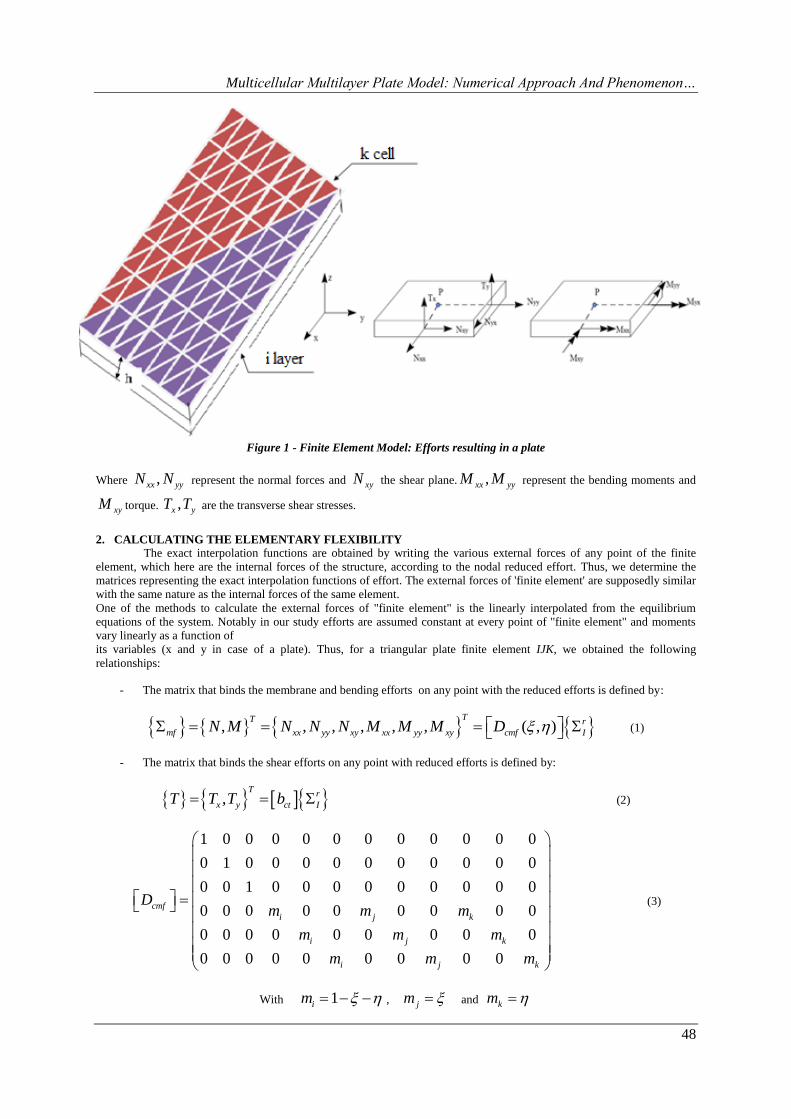
Figure 1 - Finite Element Model: Efforts resulting in a plate
Where ,xx yyN N represent the normal forces and xyN the shear plane. ,xx yyM M represent the bending moments and
xyM torque. ,x yT T are the transverse shear stresses.
2. CALCULATING THE ELEMENTARY FLEXIBILITY
The exact interpolation functions are obtained by writing the various external forces of any point of the finite
element, which here are the internal forces of the structure, according to the nodal reduced effort. Thus, we determine the
matrices representing the exact interpolation functions of effort. The external forces of 'finite element' are supposedly similar
with the same nature as the internal forces of the same element.
One of the methods to calculate the external forces of "finite element" is the linearly interpolated from the equilibrium
equations of the system. Notably in our study efforts are assumed constant at every point of "finite element" and moments
vary linearly as a function of
its variables (x and y in case of a plate). Thus, for a triangular plate finite element IJK, we obtained the following
relationships:
- The matrix that binds the membrane and bending efforts on any point with the reduced efforts is defined by:
, , , , , , ( , )TT r
mf xx yy xy xx yy xy cmf IN M N N N M M M D (1)
- The matrix that binds the shear efforts on any point with reduced efforts is defined by:
,T
r
x y ct IT T T b (2)
1 0 0 0 0 0 0 0 0 0 0 0
0 1 0 0 0 0 0 0 0 0 0 0
0 0 1 0 0 0 0 0 0 0 0 0
0 0 0 0 0 0 0 0 0
0 0 0 0 0 0 0 0 0
0 0 0 0 0 0 0 0 0
cmf
i j k
i j k
i j k
Dm m m
m m m
m m m
(3)
With 1im , jm and km
Multicellular Multilayer Plate Model: Numerical Approach And Phenomenon…
49
1 2 3 4 5 6
2 1 4 3 6 5
0 0 0 0 0 0
0 0 0 0 0 0ct
b b b b b bb
b b b b b b
(4)
1
1
J Ky yb
S
, 2
1
K Jx xb
S
, 3
1
K Iy yb
S
, 4
1
I Kx xb
S
, 5
1
I Jy yb
S
, 6
1
J Ix xb
S
1 ( ) ( ) ( )I K J J I K K J Is y x x y x x y x x is twice the area of the triangle IJK
1 2 3, , , , , , , , , , ,I I I J J J K K K
Tr
I xx yy xy xx yy xy xx yy xyN N N M M M M M M M M M
(5)
Where r
I the vector of nodal efforts reduced, ( , )cmfD and ctb are the matrices that represent accurate
interpolation functions of the efforts membrane bending and shear respectively in the absence of apportionment. The
stiffness matrix is simply the inverse of the flexibility matrix.
cmf and ,x yT T are respectively the vector normal forces, effort membrane, bending moments, twisting moment and
shear forces applied to the cell.
The direct connection of the finite element provides the stiffness matrix of elementary model in the local
coordinate expressed by:
1Te e
flxK R F R
(6)
11
( ) ( )e pla pla
flx flx flxF F cmf F cis
(7)
Where ( )pla
flxF cmf and ( )pla
flxF cis are respectively the flexibilities of the matrices membrane combination
bending and shearing of the plate. R is the transition matrix to the system without rigid modes of deformation within five
degrees of freedom, whose force field is represented by equation (8) and the corresponding displacements q are defined
(eqt.9):
Tplaq r
IF R (8)
eq R u (9)
With plaqF the external force exerted by a plate finite element nodal loads equivalent to the same element and eu the
corresponding vector of nodal displacements and is given by equation (10):
0 0 0 0 0 0 , 0 0 0, , , , , , , , , , , , ,I I I I I J J J J J K K K K K
Te
x y x y x yu u v w u v w u v w (10)
Remark: In the simple case of a beam with two nodes with three degrees of freedom [23] the force vector corresponds
exactly to the demands of the nodal finite element beam.
Flexibility matrices concerning the plates are given by: cells
1
1
( ) ( , ) ( , ) ( , )m
Tpla
flex IJK cmf cmf K K cmf
k
F cmf S D H D d d
(11)
cells
1
1
( ) ( , )m
Tpla
flex IJK ct ct K K ct
k
F cisaill S b H b d d
(12)
Multicellular Multilayer Plate Model: Numerical Approach And Phenomenon…
50
The matrices 1
( , )cmf K KH
and 1
( , )ct K KH
are matrices named flexibilities membrane bending and shear
respectively:
( , ) ( , ) ( , )cmf K K cmf K K cmf K KD H d and ( , )ct ct K K ctb H d
( , )mf
m mf
Tcmf K Kf
H HH
H H
and
strata
1
( , )N
c K K i i
i
H h H
with
strata
1
N
m i i
i
H h H
,
strata3 3
1
1
1( )
3
N
f i i i
i
H z z H
and
strata
1
N
mf i i i
i
H h H
2
1 0
1 01
10 0
2
i
ii i
i
i
EH
and
'
2 '
(1 )0
2
1 (1 )0
2
i
ii
i i
k
EH
k
1i i ih z z , 1
1( )
2i i iz z
The matrices ( , )cmf K KH and ( , )c K KH respectively represent the stiffness of membrane bending and
shearing of the cell k of the plate, hi and Zi represent respectively the thickness and position Z layer i of the cell, iE and i
being respectively the Young's modulus and Poisson's ratio of the corresponding layer. 'k is the shear correction factor.
'( , ) , , , , ,cmf K K xx yy xy xx yy xyd e e k k is the vector of plane deformation, and membrane of curvature
experienced by a cell, and ,ct x yd is the vector of deformations of the distortion in the planes (x, z) and (y, z).
3. PRESENTATION OF AN ELEMENT DKT (Discrete Kirchhoff Triangle)
The DKT element defined in [1] is a finite element with three nodes and three degrees of freedom per node. It is
considered in this article, as a finite element with three nodes and five degrees of freedom per node.
The rotations x , y are interpolated in a parabolic manner and the transverse displacements 0 0 0, ,u v w are interpolated
in a linear manner [1, 2]:
2
1 1i k
n n
x i x x k
i k n
N P
,
2
1 1i k
n n
y i y y k
i k n
N P
, kx k kP P C and
ky k kP P S
0 0
1i
n
i
i
u N u
, 0 0
1i
n
i
i
v N v
, 0 0
1i
n
i
i
w N w
Where kC , kS are the direction cosines, k is the middle of respective sides of the triangle, and are given by the side
ij: ( ) /k j i kC x x L , ( ) /k j i kS y y L and 2 2( ) ( )k j i j iL x x y y
Where n is the number of nodes of the finite element, in the case of a triangular element 3n and functions iN and kP
are given by [1, 2]:
1 1N , 2N , 3N , 4 4P , 5 4P and 6 4P
The expression of k according to the nodal variables of nodes i and j is [1]:
Multicellular Multilayer Plate Model: Numerical Approach And Phenomenon…
51
3 3( ) ( )
2 4 i i j jk i j k x k y k x k y
k
w w C S C SL
(13)
So: 1 2 3
1 2 3
x x xx i i i
ny y yy i i i
N N Nu
N N N
(14)
1
3 3
2 2
x
i k k m m
k m
N P C P CL L
,2 2
2
3 3
4 4k m
x
i i k mN N P C P C ,3
3 3
4 4
x
i k k k m m mN P C S P C S
1
3 3
2 2
y
i k k m m
k m
N P S P SL L
, 2 3
y x
i iN N , 2 2
3
3 3
4 4k m
y
i i k mN N P S P S for 1,...i n
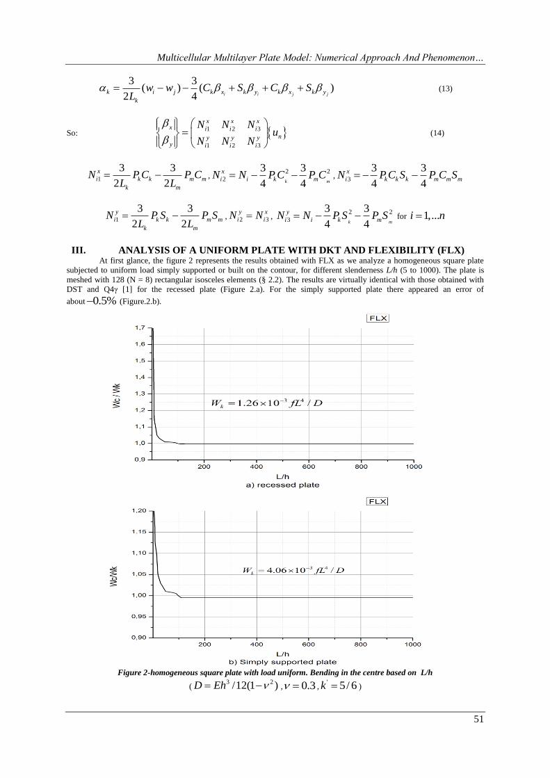
III. ANALYSIS OF A UNIFORM PLATE WITH DKT AND FLEXIBILITY (FLX) At first glance, the figure 2 represents the results obtained with FLX as we analyze a homogeneous square plate
subjected to uniform load simply supported or built on the contour, for different slenderness L/h (5 to 1000). The plate is
meshed with 128 (N = 8) rectangular isosceles elements (§ 2.2). The results are virtually identical with those obtained with
DST and Q4γ [1] for the recessed plate (Figure 2.a). For the simply supported plate there appeared an error of
about 0.5% (Figure.2.b).
Figure 2-homogeneous square plate with load uniform. Bending in the centre based on L/h
(3 2/12(1 )D Eh , 0.3 ,
' 5/ 6k )
Multicellular Multilayer Plate Model: Numerical Approach And Phenomenon…
52
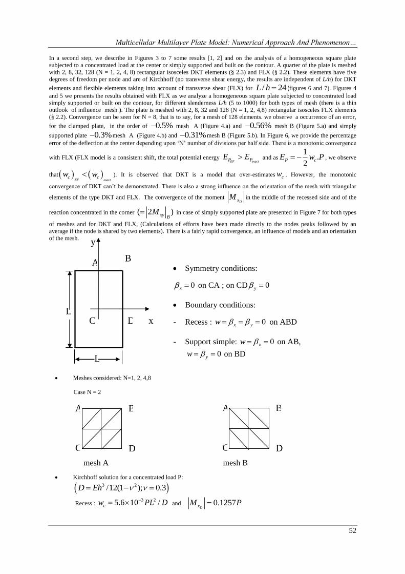
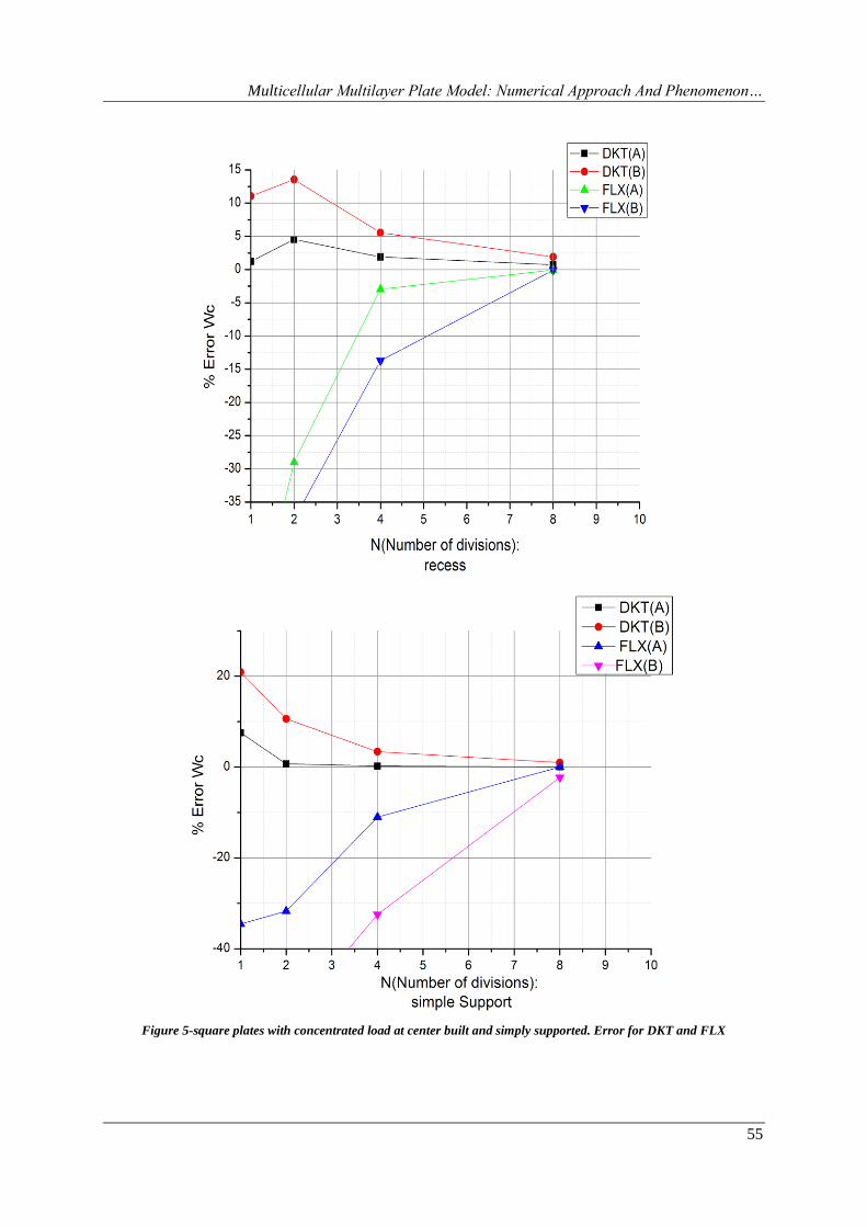
In a second step, we describe in Figures 3 to 7 some results [1, 2] and on the analysis of a homogeneous square plate
subjected to a concentrated load at the center or simply supported and built on the contour. A quarter of the plate is meshed
with 2, 8, 32, 128 (N = 1, 2, 4, 8) rectangular isosceles DKT elements (§ 2.3) and FLX (§ 2.2). These elements have five
degrees of freedom per node and are of Kirchhoff (no transverse shear energy, the results are independent of L/h) for DKT
elements and flexible elements taking into account of transverse shear (FLX) for / 24L h (figures 6 and 7). Figures 4
and 5 we presents the results obtained with FLX as we analyze a homogeneous square plate subjected to concentrated load
simply supported or built on the contour, for different slenderness L/h (5 to 1000) for both types of mesh (there is a thin
outlook of influence mesh ). The plate is meshed with 2, 8, 32 and 128 (N = 1, 2, 4,8) rectangular isosceles FLX elements
(§ 2.2). Convergence can be seen for N = 8, that is to say, for a mesh of 128 elements. we observe a occurrence of an error,
for the clamped plate, in the order of 0.5% mesh A (Figure 4.a) and 0.56% mesh B (Figure 5.a) and simply
supported plate 0.3% mesh A (Figure 4.b) and 0.31% mesh B (Figure 5.b). In Figure 6, we provide the percentage
error of the deflection at the center depending upon „N‟ number of divisions per half side. There is a monotonic convergence
with FLX (FLX model is a consistent shift, the total potential energy EF exactP PE E and as
1.
2P cE w P , we observe
that EF exact
c cw w ). It is observed that DKT is a model that over-estimates cw . However, the monotonic
convergence of DKT can‟t be demonstrated. There is also a strong influence on the orientation of the mesh with triangular
elements of the type DKT and FLX. The convergence of the moment DxM in the middle of the recessed side and of the
reaction concentrated in the corner ( 2 )xy BM in case of simply supported plate are presented in Figure 7 for both types
of meshes and for DKT and FLX, (Calculations of efforts have been made directly to the nodes peaks followed by an
average if the node is shared by two elements). There is a fairly rapid convergence, an influence of models and an orientation
of the mesh.
Meshes considered: N=1, 2, 4,8
Case N = 2
Kirchhoff solution for a concentrated load P:
3 2/12(1 ); 0.3D Eh
Recess : 3 25.6 10 /cw PL D and 0.1257
DxM P
B
D
A
y
x C
L
L
Symmetry conditions:
0x on CA ; on CD 0y
Boundary conditions:
- Recess : 0x yw on ABD
- Support simple: 0xw on AB,
0yw on BD
C
A B
D C
A B
D
mesh A mesh B
Multicellular Multilayer Plate Model: Numerical Approach And Phenomenon…
53
- Simple Support: 3 211.6 10 /cw PL D and 2 0.1219xy B
R M P
Figure 3-square plate under concentrated load. Data
Figure 4-homogeneous square plate with concentrated load. Arrow in the center in terms of L / h (mesh A)
Multicellular Multilayer Plate Model: Numerical Approach And Phenomenon…
54
Figure 5-homogeneous square plate with concentrated load. Arrow in the center in terms of L / h(mesh B)
Where Wk the numerical value calculated for the different divisions (N = 1, 2, 4.8)
Multicellular Multilayer Plate Model: Numerical Approach And Phenomenon…
55
Figure 5-square plates with concentrated load at center built and simply supported. Error for DKT and FLX
Multicellular Multilayer Plate Model: Numerical Approach And Phenomenon…
56
Figure 6-square plates with concentrated load at center built and simply supported. Error on a moment and a reaction in
the corner for DKT and FLX
IV. CONCLUSION The flexibility method developed with a linear interpolation (interpolation functions of the first order) and of way
independently of the transverse displacements and rotations, solves the problem related to the phenomenon by
shear locking. In the case of multicellular multilayer finite element, we observe that the method of flexibility,
which is a model monotone convergence, converges quickly enough for a plate structure. In this paper we have
presented the results for the analysis of a square plate in bending under load concentrated at the center, simply
supported on the contour or clamped while highlighting the influence of the mesh on different slenderness L / h
(Figures 4 and 5: arrow report /c kw w ). We also presented results on an analysis of a square plate subjected to a
uniform load, clamped or simply supported on the contour (Figure 2). The percentage error appeared in Figures 4,
5, 6 and 7 and that can be translated by the phenomenon of blocking is reduced (becomes negligible) by increasing
the number of elements this allows us to confirm the reliability of the method on solving the problem of shear
locking. In the following work (in a future article) we present the results at predictive calculation of the
performance of bearing subject to the sails seismic behavior by numerical simulation coupled with a damage
model by comparison with experimental results and by adopting a damage model for multicellular multilayer
finite element .
Multicellular Multilayer Plate Model: Numerical Approach And Phenomenon…
57
REFERENCES 1. Batoz J.L. & GOURI Dhatt « Modélisation des structures par éléments finis Volume 2 Poutres et Plaques
2. Batoz J.L. & GOURI Dhatt « Modélisation des structures par éléments finis Volume 1, Volume 2, Volume 3 »
Editions HERMES 34, rue Eugène Flachat 75017 PARIS.
3. Crisfield M.A., [1991]. “Nonlinear Finite Element analysis of solids and structures”. Vol I, John Wiley,
Chichester.
4. D. Bui, "Le cisaillement dans les plaques et les coques : modélisation et calcul", Note HI-71/7784, 1992.
5. De Ville de Goyet V., [1989]. “L‟analyse statique non linéaire par la méthode des éléments finis des structures
spatiales formées de poutres à section non symétrique”. Thèse de doctorat, Université de Liège.