9.3.2015 CALPEX district heating pipe CPX Subject to technical changes Table of Contents 1.0 Table of Contents 1.1 System description 1.100 System description (general) 1.105 System description (data) 1.106 System description (data) 1.110 Long-term behaviour/lifetime calculation 1.115 CALPEX UNO range, heating 6 bar – structure, dimensions, materials, weights and delivery lengths 1.116 CALPEX DUO range, heating 6 bar – structure, dimensions, materials, weights and delivery lengths 1.120 CALPEX UNO/DUO range, sanitary 10 bar – structure, dimensions, materials, weights and delivery lengths 1.125 CALPEX QUADRIGA range, heating 6 bar, sanitary 10 bar – structure, dimensions, materials, weights and delivery lengths 1.2 Planning, design engineering 1.200 Pressure loss chart, heating, 6 bar 1.205 Pressure loss chart, sanitary, 10 bar 1.210 Heat loss, heating, 6 bar 1.215 Heat loss, sanitary, 10 bar 1.220 Heat loss, heating 6 bar, sanitary 10 bar, QUADRIGA 1.225 Planning and connection technology, heating strip, sanitary, 10 bar 1.3 Components 1.300 House entry bend 90°, heating 6 bar, UNO and DUO 1.305 House entry bend 90°, sanitary 10 bar, UNO and DUO 1.310 House entry bend 90°, heating 6 bar, sanitary 10 bar, QUADRIGA 1.315 CALPEX L-shell 1.316 CALPEX Big L-shell 1.320 Joint (PE-HD shrink sleeve) 1.325 CALPEX I-shell 1.326 CALPEX Big I-shell 1.330 CALPEX T-shell 1.335 CALPEX Big T-shell 1.340 T-joint 1.345 Y-pipe, heating, 6 bar 1.350 Distribution chamber 1.355 Distribution chamber, installation 1.360 Concrete protective plate for distribution shaft 1.365 Insulation material, PE foam PUR foam containers 1.0 1.370 Screwed connectors, outer thread, weld end 1.375 Screwed connectors, coupling: equal, reduced 1.380 Screwed connectors, T-piece 1.385 Compression connectors, thread, weld end with sliding sleeve 1.390 Compression connectors, coupling, angle 90° with sliding sleeve 1.395 Compression T-piece, with sliding sleeve 1.400 Electro-fusion joint 1.405 End cap, standard, shrinkable 1.410 Wall sealing ring, for wall openings 1.415 Building entry, wall opening/core bore 1.420 Wall seal, core bores/cement pipe liners 1.425 Building entry, core bores/cement pipe liners 1.430 Pipe warning tape 1.5 Underground construction, installation 1.500 Pipe routing 1.505 Trench dimensions 1.510 Connection (rigid/flexible), CALPEX plastic casing pipe 1.515 House entry, screwed connector, shaft entry, fixed point forces 1.520 House connection, compression joint, shaft entry, fixed point forces 1.525 Installation of house entry 1.530 Installation tool, general and for screwed connector 1.535 Installation tool, for joint with sliding sleeves 1.540 Heating strip, sanitary, 10 bar, drawing in, sensor, joint
Transcript
9.3.2015
CALPEX district heating pipe CPX
Subject to technical changes
Table of Contents
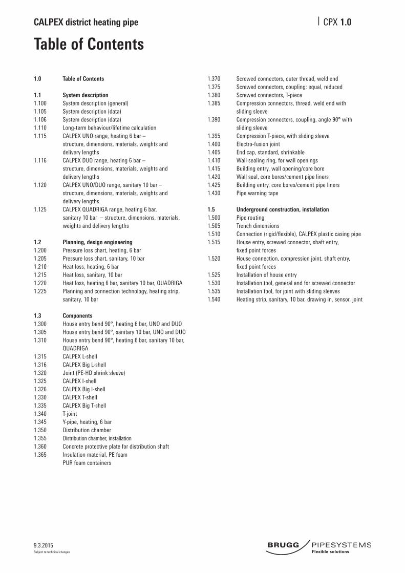
1.0 Table of Contents
1.1 System description 1.100 System description (general)1.105 System description (data)1.106 System description (data)1.110 Long-term behaviour/lifetime calculation1.115 CALPEX UNO range, heating 6 bar – structure, dimensions, materials, weights and delivery lengths1.116 CALPEX DUO range, heating 6 bar – structure, dimensions, materials, weights and delivery lengths1.120 CALPEX UNO/DUO range, sanitary 10 bar – structure, dimensions, materials, weights and delivery lengths1.125 CALPEX QUADRIGA range, heating 6 bar, sanitary 10 bar – structure, dimensions, materials,
weights and delivery lengths
1.2 Planning, design engineering1.200 Pressure loss chart, heating, 6 bar1.205 Pressure loss chart, sanitary, 10 bar1.210 Heat loss, heating, 6 bar 1.215 Heat loss, sanitary, 10 bar1.220 Heat loss, heating 6 bar, sanitary 10 bar, QUADRIGA1.225 Planning and connection technology, heating strip, sanitary, 10 bar
1.3 Components1.300 House entry bend 90°, heating 6 bar, UNO and DUO1.305 House entry bend 90°, sanitary 10 bar, UNO and DUO1.310 House entry bend 90°, heating 6 bar, sanitary 10 bar,
QUADRIGA1.315 CALPEX L-shell1.316 CALPEX Big L-shell1.320 Joint (PE-HD shrink sleeve)1.325 CALPEX I-shell1.326 CALPEX Big I-shell1.330 CALPEX T-shell 1.335 CALPEX Big T-shell 1.340 T-joint 1.345 Y-pipe, heating, 6 bar1.350 Distribution chamber1.355 Distribution chamber, installation1.360 Concrete protective plate for distribution shaft1.365 Insulation material, PE foam PUR foam containers
1.0
1.370 Screwed connectors, outer thread, weld end1.375 Screwed connectors, coupling: equal, reduced1.380 Screwed connectors, T-piece1.385 Compression connectors, thread, weld end with sliding sleeve1.390 Compression connectors, coupling, angle 90° with sliding sleeve1.395 Compression T-piece, with sliding sleeve 1.400 Electro-fusion joint1.405 End cap, standard, shrinkable1.410 Wall sealing ring, for wall openings1.415 Building entry, wall opening/core bore1.420 Wall seal, core bores/cement pipe liners1.425 Building entry, core bores/cement pipe liners1.430 Pipe warning tape
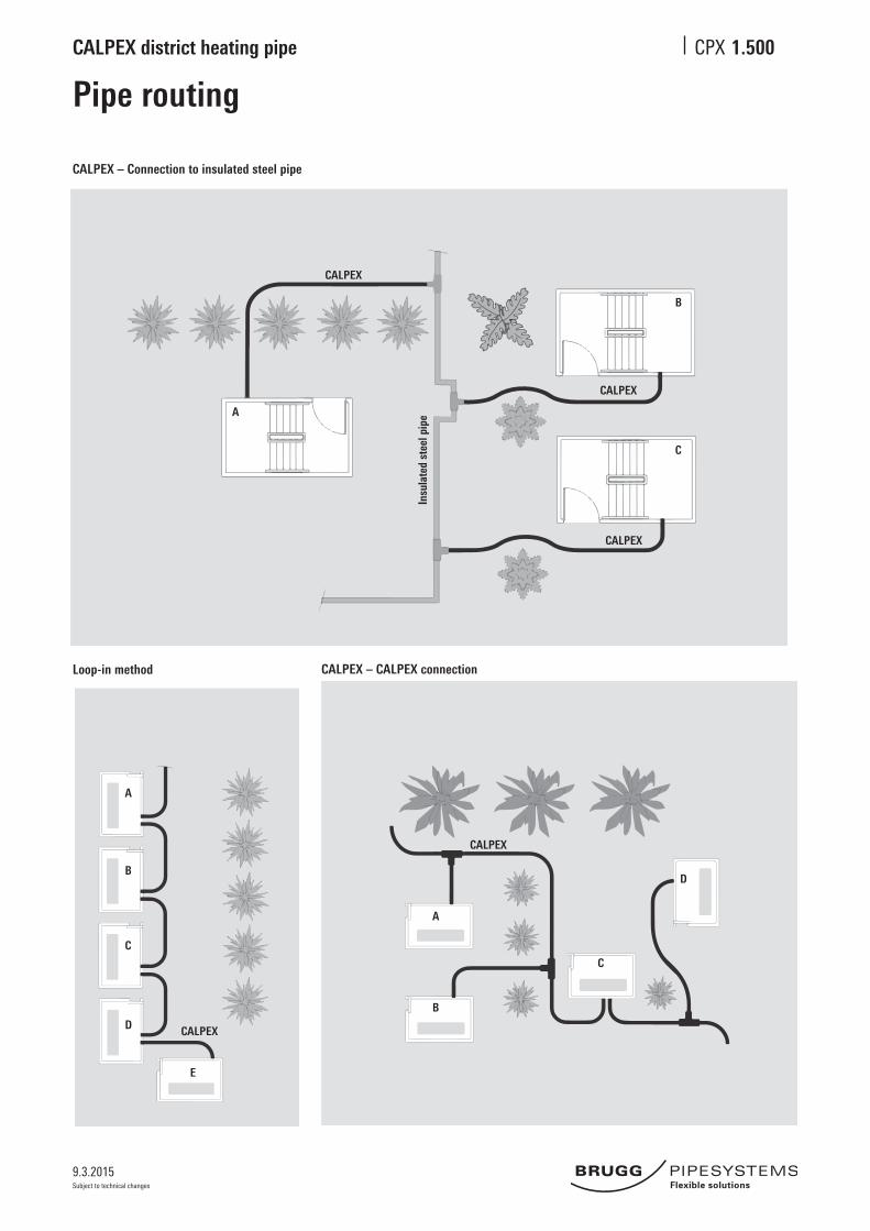
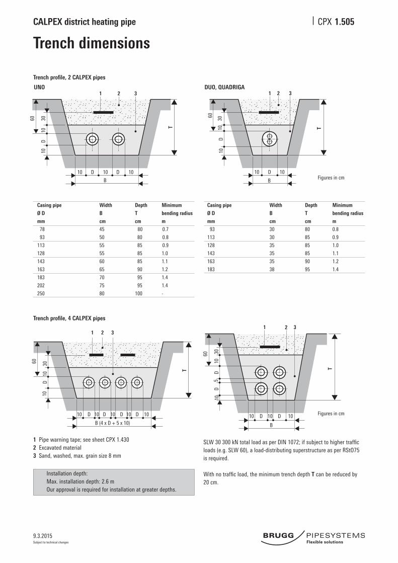
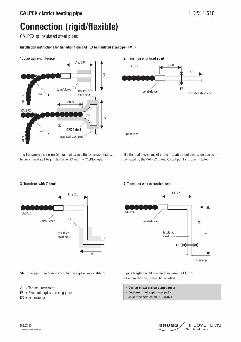
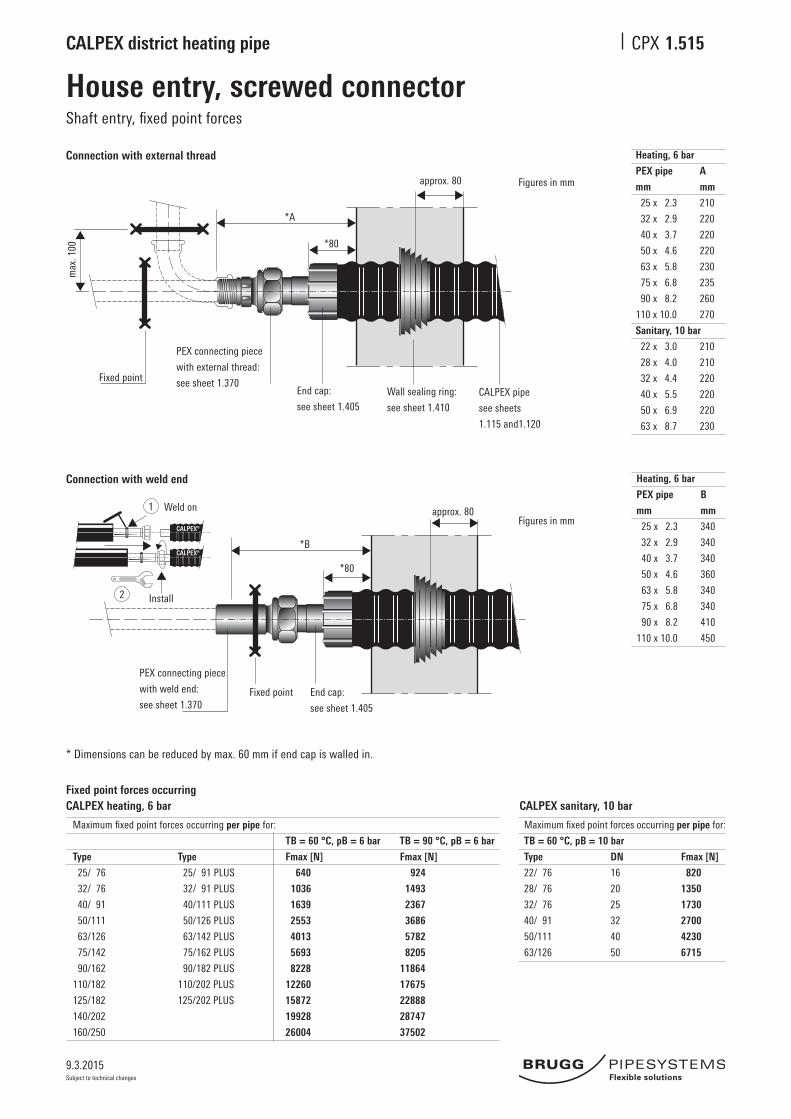
1.5 Underground construction, installation1.500 Pipe routing1.505 Trench dimensions1.510 Connection(rigid/flexible),CALPEXplasticcasingpipe1.515 House entry, screwed connector, shaft entry, fixedpointforces1.520 House connection, compression joint, shaft entry, fixedpointforces1.525 Installation of house entry1.530 Installation tool, general and for screwed connector1.535 Installation tool, for joint with sliding sleeves1.540 Heating strip, sanitary, 10 bar, drawing in, sensor, joint
9.3.2015
CALPEX district heating pipe CPX
Subject to technical changes
System description
1. General
CALPEXdistrictheatingpipeistheregisteredtradenameforaflexiblepipesystemfromBruggPipeSystems,specificallydesignedforthelowtemperatureuse.Itisidealforuseinsmallandmidsize district and local heating networks, in industrial and agricultural applications, for drink-ing water supplies, sewage systems, cooling systems and swimming pool installations.
CALPEX district heating pipe has a carrier pipe made of cross-linked polyethylene, PEXa. Thismaterialwasselectedbecauseofitsexcellentthermalandmechanicalproperties.Itisacorrosion-proof and chemically resistant material. The product is free of harmful substances, makingitexceptionallyenvironment-friendly.
The bending capability of CALPEX district heating pipe means that it is generally possible to passoverorunderexistingsupplypipesandobstaclescanbeeasilybypassed.
With CALPEX district heating pipe, users can choose the shortest pipe route without the restric-tions required by the classical method of pipe construction.
TheflexibleCALPEXdistrictheatingpipeisdeliveredtothesitecontinuouslyincoilsoronacable drum. Long delivery lengths enable pipes to be laid in the ground largely without joints. This means that the pipe trench can be considerably narrower. This in turn allows considerable savings on underground work, especially as regards DUO pipes.
Taking account of the very short time required for installation, CALPEX district heating pipe is notonlythetechnicallyidealsolutionbutalsothekeytosavingtimeandexpensewhensettingup district heating networks; less co-ordination is required on site and the pipes are laid simply and quickly.
The physical properties of the PEXa pipe combined with the composite insulation mean that thermalexpansioncanbeignoredwhenusingthisproduct.
Installingtheconnectingpiecesisverysimple.Thejointsarefittedquicklyandreliablywithconventional screwed connectors, compression joints or electro-fusion joints. The wide range of accessories ensures that solutions can be chosen for every possible situation.
CALPEX district heating pipes are manufactured according to the current standard (EN 15632-1 /-2).
2. Range of applications
Heating, pipe series 5 (SDR 11): Max.temp.forcontinuous operation TBmax: 80 °CMax.permittedoperating temp. Tmax: 95 °C(fluctuating)Max.permittedoperating pressure p: 6 bar
see sheet CPX 1.110
Sanitary, pipe series 3.2 (SDR 7.4):Max.temp.forcontinuous operation TBmax: 80 °CMax.permittedoperating temp. Tmax: 95 °C(fluctuating)Max.permittedoperating pressure p: 10 bar
see sheet CPX 1.110
1.100
9.3.2015
CALPEX district heating pipe CPX
Subject to technical changes
PEXa carrier pipe Reference temperature °C Value Test standard
Density - 932 - 935 kg/m3 ISO 1183
Thermal conductivity - 0.38 W/mK in Anlehnung an ASTM C 1113
Tensil strength 20 min. 18 N/mm2 ISO 6259
Tensil strength 80 min. 8 N/mm2 ISO 6259
Modulus of elasticity 20 600 N/mm2 ISO 527
Modulus of elasticity 80 200 N/mm2 ISO 527
Linearexpansioncoefficient 20 1.4·10E-41/K -
Linearexpansioncoefficient 100 2.0·10E-41/K -
Crystallite melting range - 128 - 134 °C -
Chem. resistance 20 / 40 / 60 - DIN 8075 B.1
System description
2. Carrier pipe
Materials Basicmaterial:High-densitypolyethylene(PE-HD),peroxidecross-linked(PEXa),colour:naturalBondingagent PE-modified,heat-stabilized,colour:red(heating),silver(sanitary)Oxygenbarrierlayer Ethylene / vinylalcohol(EVOH),heat-stabilized,colour:naturalRequirements As per DIN 16892 / DIN 16893 and E DIN EN 12318-2, pipes in series 3.2
asperDVGWworksheetW544Impermeabilitytooxygen AsperDIN4729at40 °C,oxygenpermeabilitybasedontheinteriorpipevolume asperDIN4726from≤0.10g / (m3 x d)Pipe series DIN 16893 Series5(SDR11):forheating(withEVOHbarrier)
Series3.2(SDR7.4):forsanitary(withEVOHbarrier)Long-term behaviour See catalog sheet CPX 1.110Properties Unaffected by aggressive water; low pressure losses; very good chemical and mechanical resistance
Materials: linearpolyethylene,lowdensity(LLD-PE),seamlesslyextrudedPurpose: mechanical protection and moisture resistance
LLD-PE protective casing Reference temperature °C Value Test standard
Density - 918 - 922 kg/m3 ISO 1183
Thermal conductivity - 0.33 W/mK DIN 52612
Crystallite melting range - 122 °C ISO 11357-3
Note:Due to the planned revision of standards, the heat losses are not shown as specified within EN 15632.
9.3.2015
CALPEX district heating pipe CPX
Subject to technical changes
1.110
Long-term behaviourLifetime calculation
Long-term behaviour: (table)
The values have a safety factor of 1.25 and are based on a series ofmeasurements covering an average of 32,000 hours. They can becompared with Table 5 as per DIN 16893. All values have been testedandconfirmedbythecompetentorganizationsinvariouscountries.Themax.operatingtemperatureis95°Cbutconsidersashort-termover temperature (fault temperature) of 110 °C.Atypicalfluctuatingtemperaturedistributionfortheflowinadistrictheatingsystemgivesanaveragetemperature/yearofapprox.66°C.
Lifetime calculation using Miner‘s Rule
Lifetimecalculationforfluctuatingoperatingtemperatureswillbecalculated acc. EN ISO 13760.
Example of application
Thebasisisatypicaltemperaturecollectiveoveroneyear,withfluctu-ating operation. (gem. EN 15632-2)
1 year = 365 days = 8760 hours.
Operating
Temperature
°C
95
90
85
80
75
70
65
60
total
Example 1
Annual
Operating time
h
3,3
292
0
8468
0
0
0
0
8763,3
Example 2
Annual
Operating time
h
0
50
100
200
2000
2410
4000
0
8760
Example 3
Annual
Operating time
h
0
50
1000
3450
1000
0
0
0
5500
Operating temperature: Heating (pipe series 5 / SDR 11) Sanitary (pipe series 3.2 / SDR 7.4)
°C Operating pressure (bar) Operating pressure (bar)
1 year 5 year 10 year 25 year 50 year 1 year 5 year 10 year 25 year 50 year
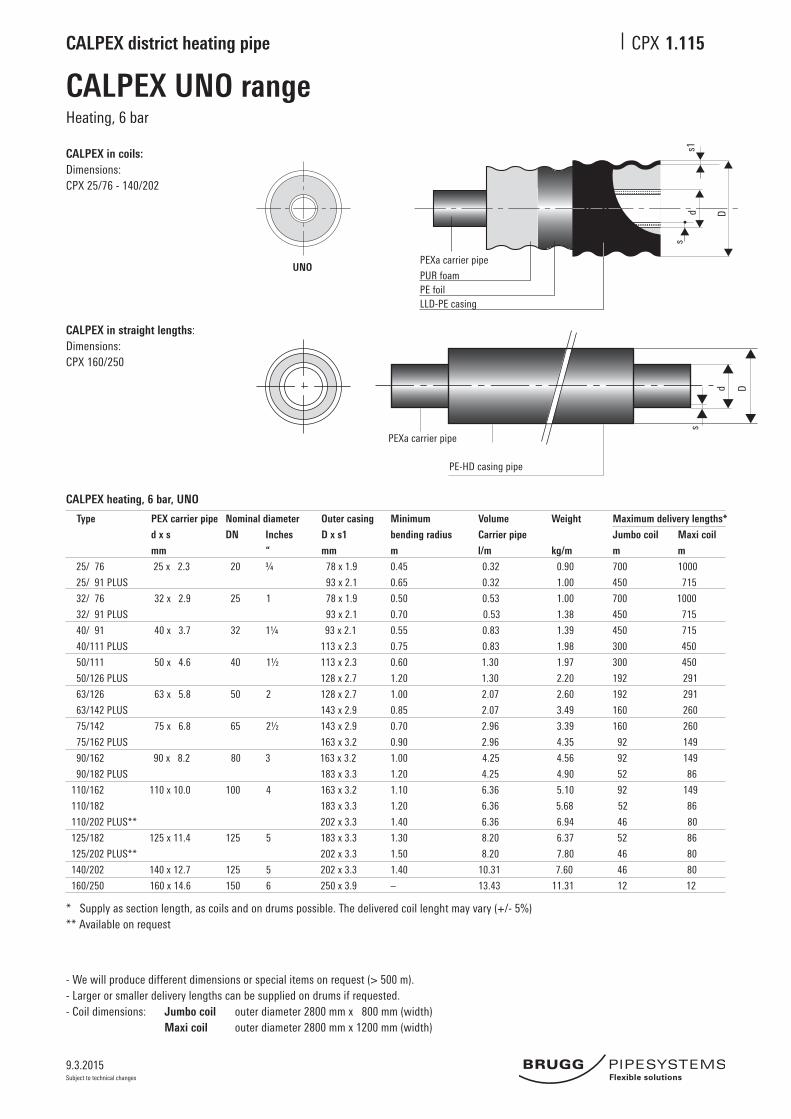
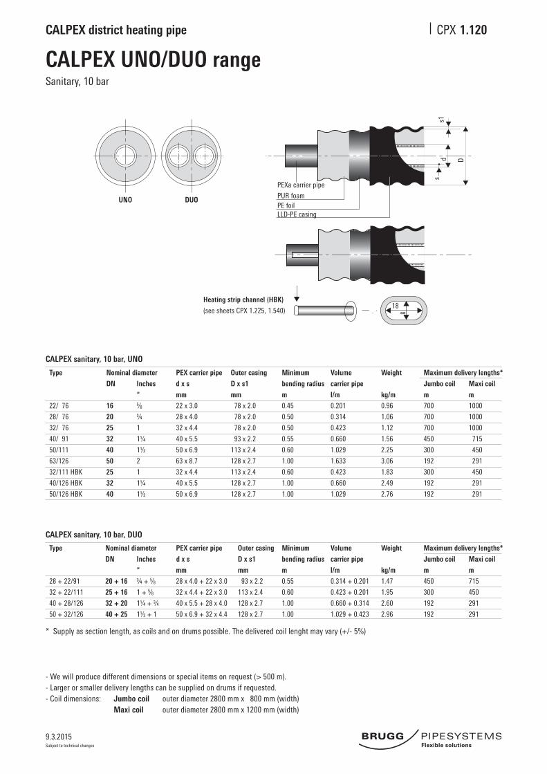
- We will produce different dimensions or special items on request (> 500 m).- Larger or smaller delivery lengths can be supplied on drums if requested.- Coil dimensions: Jumbo coil outerdiameter2800mmx800mm(width) Maxi coil outerdiameter2800mmx1200mm(width)
- We will produce different dimensions or special items on request (> 500 m).- Larger or smaller delivery lengths can be supplied on drums if requested.- Coil dimensions: Jumbo coil outerdiameter2800mmx800mm(width) Maxi coil outerdiameter2800mmx1200mm(width)
- We will produce different dimensions or special items on request (> 500 m).- Larger or smaller delivery lengths can be supplied on drums if requested.- Coil dimensions: Jumbo coil outerdiameter2800mmx800mm(width) Maxi coil outerdiameter2800mmx1200mm(width)
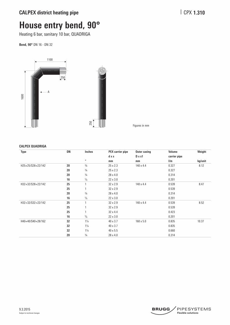
CALPEX QUADRIGA rangeHeating 6 bar, sanitary 10 bar
Type
H25+25/S28+22/142
H32+32/S28+22/142
H32+32/S32+22/142
H40+40/S40+28/162
Nominal diameter
DN
20
20
20
16
25
25
20
16
25
25
25
16
32
32
32
20
Inches
“
¾
¾
¾5⁄8
1
1
¾5⁄81
1
15⁄81¼
1¼
1¼
¾
Carrier pipe
d x s
mm
25x2.3
25x2.3
28x4.0
22x3.0
32x2.9
32x2.9
28x4.0
22x3.0
32x2.9
32x2.9
32x4.4
22x3.0
40x3.7
40x3.7
40x5.5
28x4.0
Outer casing
D x s1
mm
143x3.0
143x3.0
143x3.0
163x3.2
Minimum
bending radius
m
0.7
0.7
0.7
1.1
Volume
carrier pipe
l/m
0.327
0.327
0.314
0.201
0.539
0.539
0.314
0.201
0.539
0.539
0.423
0.201
0.835
0.835
0.660
0.314
Weight
kg/m
3.25
3.39
3.41
4.15
Jumbo coil
m
110
110
110
65
Maxi coil
m
180
180
180
105
Maximum delivery length*
- We will produce different dimensions or special items on request (> 500 m).- Larger or smaller delivery lengths can be supplied on drums if requested.- Coil dimensions: Jumbo coil outerdiameter2800mmx800mm(width) Maxi coil outerdiameter2800mmx1200mm(width)
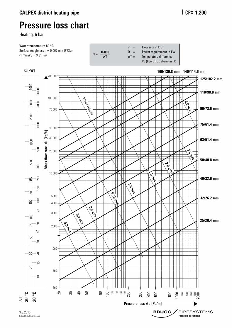
Water temperature 80 °CSurface roughness ε = 0.007 mm (PEXa)(1 mmWS = 9.81 Pa)
Q·860m ≈ ∆T
m = Flow rate in kg/hQ = Power requirement in kW∆T = Temperature difference VL (flow)/RL (return) in °C
9.3.2015
CALPEX district heating pipe CPX
Subject to technical changes
1.205
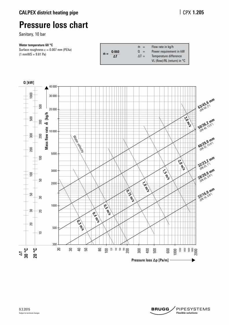
Pressure loss chartSanitary, 10 bar
Water temperature 60 °CSurface roughness ε = 0.007 mm (PEXa)(1 mmWS = 9.81 Pa)
Q·860m ≈ ∆T
m = Flow rate in kg/hQ = Power requirement in kW∆T = Temperature difference VL (flow)/RL (return) in °C
63/45,6 mm
(DN 50, 2")
50/36,2 mm
(DN 40, 11/2”)
40/29,0 mm
(DN 32, 11/4")
32/23,2 mm
(DN 25, 1”)
28/20,0 mm
(DN 20, 3/4")
22/16,0 mm
(DN 16, 5/8")
Mas
s flo
w ra
te m
[kg
/h
30 °
C
20 °
C
•
Pressure loss ∆p [Pa/m]
20 30 40 50 80 100 120
140
160
180
1200
1400
1600
1800
200
300
400
500
600
1000
2000
1020
2030
5010
020
030
050
010
00
3050
100
200
300
500
Q [kW]
∆T
2,0 m/s
3,0 m/s
1,5 m/s
1,0 m/s0,75 m
/s
0,5 m/s0,4 m
/s0,3 m/s
Water velocity
300
500
1000
2000
3000
5000
10 000
20 000
30 000
40 000
9.3.2015
CALPEX district heating pipe CPX
Subject to technical changes
1.210
Heat lossHeating, 6 bar
CALPEX UNO
Heat losses q [W/m] for one UNO pipe
CALPEX UNO U-value Average operating temperature TB [°C]
[W/mK] 40° 50° 60° 70° 80°
25/ 76 0.1142 3.43 4.57 5.71 6.85 7.99
25/ 91 PLUS 0.0993 2.98 3.97 4.97 5.96 6.95
32/ 76 0.1442 4.33 5.77 7.21 8.65 10.09
32/ 91 PLUS 0.1212 3.64 4.85 6.06 7.27 8.48
40/ 91 0.1510 4.53 6.04 7.55 9.06 10.57
40/111 PLUS 0.1236 3.71 4.94 6.18 7.42 8.65
50/111 0.1551 4.65 6.20 7.76 9.31 10.86
50/126 PLUS 0.1360 4.08 5.44 6.80 8.16 9.52
63/126 0.1767 5.30 7.07 8.84 10.60 12.37
63/142 PLUS 0.1539 4.62 6.16 7.70 9.23 10.77
75/142 0.1908 5.72 7.63 9.54 11.45 13.36
75/162 PLUS 0.1616 4.85 6.46 8.08 9.70 11.31
90/162 0.2057 6.17 8.23 10.29 12.34 14.40
90/182 PLUS 0.1747 5.24 6.99 8.74 10.48 12.23
110/162 0.2957 8.87 11.83 14.79 17.74 20.70
110/182 0.2355 7.07 9.42 11.78 14.13 16.49
110/202 PLUS 0.1992 5.98 7.97 9.96 11.95 13.94
125/182 0.3026 9.08 12.10 15.13 18.16 21.18
125/202 PLUS 0.2771 8.31 11.08 13.86 16.63 19.40
140/202 0.3084 9.25 12.34 15.42 18.50 21.59
160/250* 0.3028 9.08 12.11 15.14 18.17 21.20
Heat losses q [W/m] for one DUO pipe
CALPEX DUO U-value Average operating temperature TB [°C]
[W/mK] 40° 50° 60° 70° 80°
25+25/91 0.1786 5.36 7.14 8.93 10.72 12.50
25+25/111PLUS 0.1392 4.18 5.57 6.96 8.35 9.74
32+32/111 0.1829 5.49 7.32 9.15 10.97 12.80
32+32/126PLUS 0.1571 4.71 6.28 7.86 9.43 11.00
40+40/126 0.2108 6.32 8.43 10.54 12.65 14.76
40+40/142PLUS 0.1741 5.22 6.96 8.71 10.45 12.19
50+50/162 0.1954 5.86 7.82 9.77 11.72 13.68
50+50/182PLUS 0.1662 4.99 6.65 8.31 9.97 11.63
63+63/182 0.2381 7.14 9.52 11.91 14.29 16.67
63+63/202PLUS 0.2075 6.23 8.30 10.38 12.45 14.53
CALPEX DUO (flowandreturninonepipe)
Type of installation, CPX UNO:Type of installation, CPX DUO:Pipe distance:Cover above pipe:Ground temperature:Soil conductivity:Conductivity of PUR foam:*ConductivityofPURfoam:Conductivity of PEX pipe: Conductivity of PE pipe:
2-pipe, laid in the ground1-pipe, laid in the ground a = 0.10 mH = 0.80 mTE = 10 °CE = 1.0 W/mKPU = 0.0216 W/mKPU = 0.0260 W/mKPEXa = 0.38 W/mKPE = 0.33 W/mK
Heat loss during operation: q = U (TB -TE) [W/m]U =Heattransfercoefficient[W/mK]TB =Averageoperatingtemperature[°C]TE =Averagegroundtemperature[°C]VL =FlowRL = Return
a = 0.1 m
H =
0.8
m
TE E
TE
E
RL (return)
VL(flow)
H =
0.8
m
Note:Due to the planned revision of standards, the heat losses are not shown as specified within EN 15632..
9.3.2015
CALPEX district heating pipe CPX
Subject to technical changes
1.215
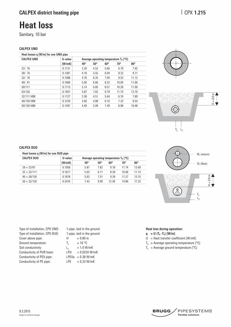
Heat lossSanitary, 10 bar
CALPEX UNO
Heat losses q [W/m] for one UNO pipe
CALPEX UNO U-value Average operating temperature TB [°C]
[W/mK] 40° 50° 60° 70° 80°
22/ 76 0.1131 3.39 4.52 5.66 6.79 7.92
28/ 76 0.1387 4.16 5.55 6.94 8.32 9.71
32/ 76 0.1588 4.76 6.35 7.94 9.53 11.12
40/ 91 0.1666 5.00 6.66 8.33 10.00 11.66
50/111 0.1713 5.14 6.85 8.57 10.28 11.99
63/126 0.1957 5.87 7.83 9.79 11.74 13.70
32/111 HBK 0.1127 3.38 4.51 5.64 6.76 7.89
40/126 HBK 0.1220 3.66 4.88 6.10 7.32 8.54
50/126 HBK 0.1497 4.49 5.99 7.49 8.98 10.48
CALPEX DUO
Heat losses q [W/m] for one DUO pipe
CALPEX DUO U-value Average operating temperature TB [°C]
[W/mK] 40° 50° 60° 70° 80°
28+22/91 0.1956 5.87 7.82 9.78 11.74 13.69
32+22/111 0.1677 5.03 6.71 8.39 10.06 11.74
40+28/126 0.1878 5.63 7.51 9.39 11.27 13.15
50+32/126 0.2476 7.43 9.90 12.38 14.86 17.33
Type of installation, CPX UNO: Type of installation, CPX DUO: Cover above pipe:Ground temperature:Soil conductivity:Conductivity of PUR foam:Conductivity of PEX pipe: Conductivity of PE pipe:
1-pipe, laid in the ground 1-pipe, laid in the groundH = 0.80 mTE = 10 °CE = 1.0 W/mKPU = 0.0234 W/mKPEXa = 0.38 W/mKPE = 0.33 W/mK
Heat loss during operation: q = U (TB -TE) [W/m] U=Heattransfercoefficient[W/mK]TB =Averageoperatingtemperature[°C]TE =Averagegroundtemperature[°C]
H =
0.8
m
TE E
TE
E
RL (return)
VL(flow)
H =
0.8
m
9.3.2015
CALPEX district heating pipe CPX
Subject to technical changes
1.220
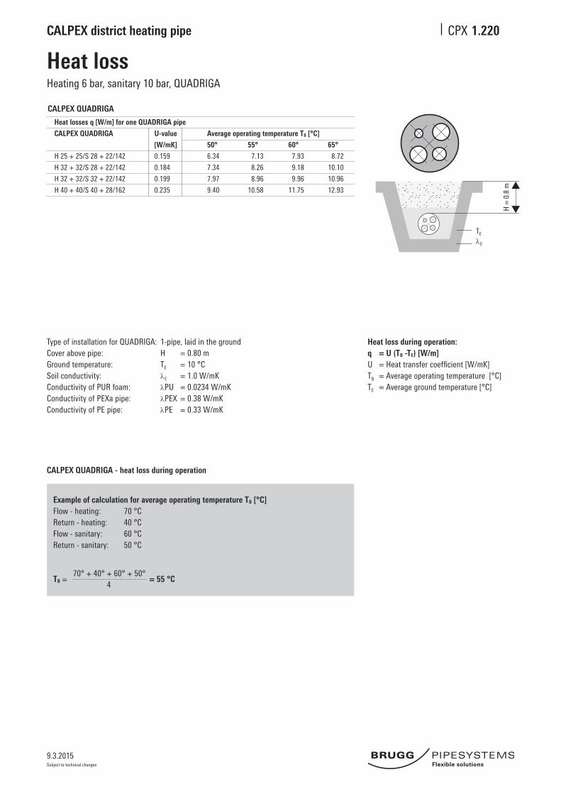
Heat lossHeating 6 bar, sanitary 10 bar, QUADRIGA
CALPEX QUADRIGA
Heat losses q [W/m] for one QUADRIGA pipe
CALPEX QUADRIGA U-value Average operating temperature TB [°C]
[W/mK] 50° 55° 60° 65°
H25+25/S28+22/142 0.159 6.34 7.13 7.93 8.72
H32+32/S28+22/142 0.184 7.34 8.26 9.18 10.10
H32+32/S32+22/142 0.199 7.97 8.96 9.96 10.96
H40+40/S40+28/162 0.235 9.40 10.58 11.75 12.93
Type of installation for QUADRIGA: Cover above pipe:Ground temperature:Soil conductivity:Conductivity of PUR foam:Conductivity of PEXa pipe: Conductivity of PE pipe:
1-pipe, laid in the ground H = 0.80 mTE = 10 °CE = 1.0 W/mKPU = 0.0234 W/mKPEX = 0.38 W/mKPE = 0.33 W/mK
CALPEX QUADRIGA - heat loss during operation
Heat loss during operation: q = U (TB -TE) [W/m] U=Heattransfercoefficient[W/mK]TB =Averageoperatingtemperature[°C]TE =Averagegroundtemperature[°C]
Example of calculation for average operating temperature TB [°C]Flow - heating: 70 °CReturn - heating: 40 °CFlow - sanitary: 60 °CReturn - sanitary: 50 °C
70°+40°+60°+50°
TB = = 55 °C
4
TE
E
H =
0.8
m
9.3.2015
CALPEX district heating pipe CPX
Subject to technical changes
1.225
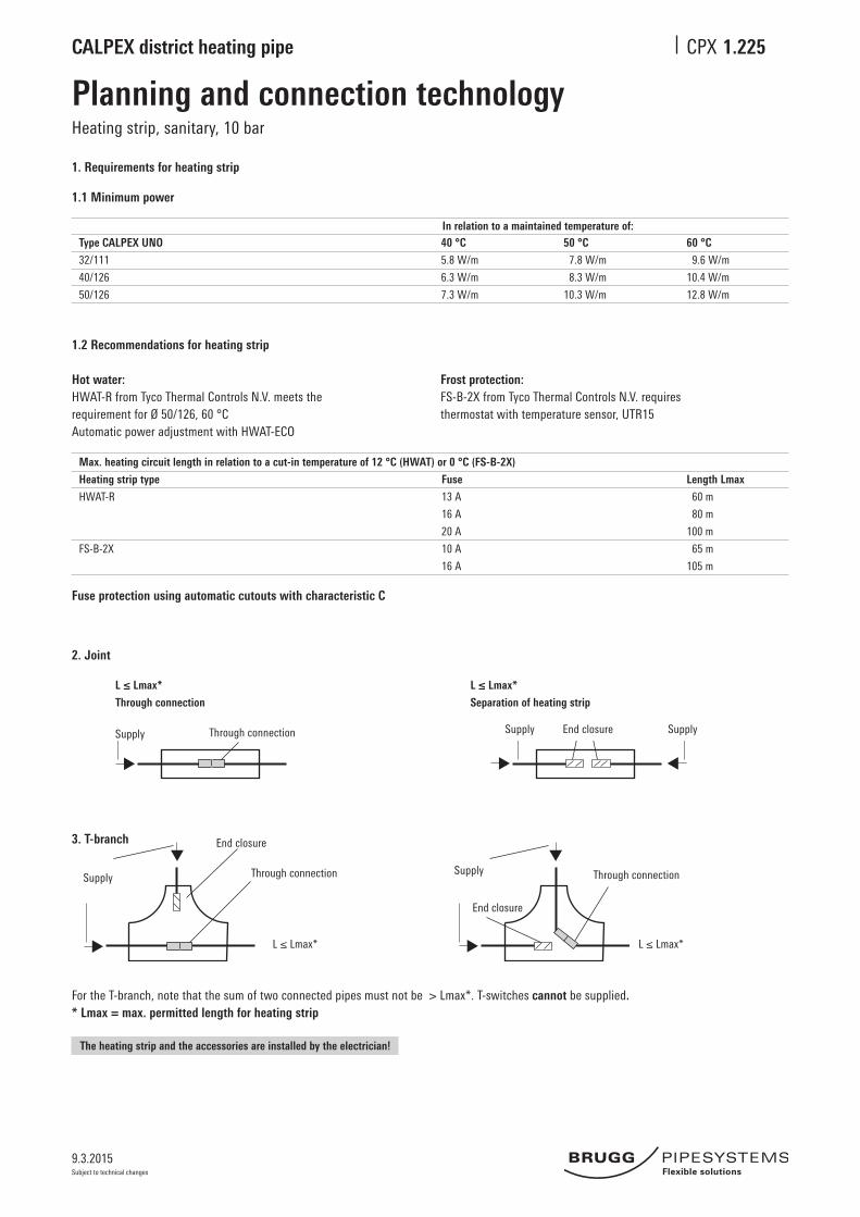
Heating strip, sanitary, 10 bar
Planning and connection technology
1. Requirements for heating strip
1.1 Minimum power
Type CALPEX UNO
32/111
40/126
50/126
40 °C
5.8 W/m
6.3 W/m
7.3 W/m
50 °C
7.8 W/m
8.3 W/m
10.3 W/m
60 °C
9.6 W/m
10.4 W/m
12.8 W/m
In relation to a maintained temperature of:
1.2 Recommendations for heating strip
Hot water: Frost protection:HWAT-R from TycoThermalControlsN.V. meets the FS-B-2X from TycoThermalControlsN.V. requiresrequirement for Ø 50/126, 60 °C thermostat with temperature sensor, UTR15 Automatic power adjustment with HWAT-ECO
Heating strip type
HWAT-R
FS-B-2X
Fuse
13 A
16 A
20 A
10 A
16 A
Length Lmax
60 m
80 m
100 m
65 m
105 m
Max. heating circuit length in relation to a cut-in temperature of 12 °C (HWAT) or 0 °C (FS-B-2X)
Fuse protection using automatic cutouts with characteristic C
2. Joint
3. T-branch
FortheT-branch,notethatthesumoftwoconnectedpipesmustnotbe>Lmax*.T-switchescannot be supplied.* Lmax = max. permitted length for heating strip
L ≤ Lmax*
Through connection
Supply Through connection
L ≤ Lmax*
Separation of heating strip
Supply SupplyEnd closure
Supply
End closure
Through connection
L≤Lmax*
Supply
End closure
Through connection
L≤Lmax*
The heating strip and the accessories are installed by the electrician!
1 ABS half-shells2 PEX angle coupling; see CPX 1.390 3 Sealing clamps (14 pcs.)4 Insulation material; see CPX 1.3655 Glued surface6 Reduction ring or sealing ring
Figures in mm
CALPEX shells are freely reducible from Ø 126 mm to Ø 76 mmCALPEX shells are not suitable for use with CALPEX QUADRIGA (distri-bution chamber: see CPX 1.350).
Note: CALPEX shells are not suggested to be installed UV exposed!
9.3.2015
CALPEX district heating pipe CPX
Subject to technical changes
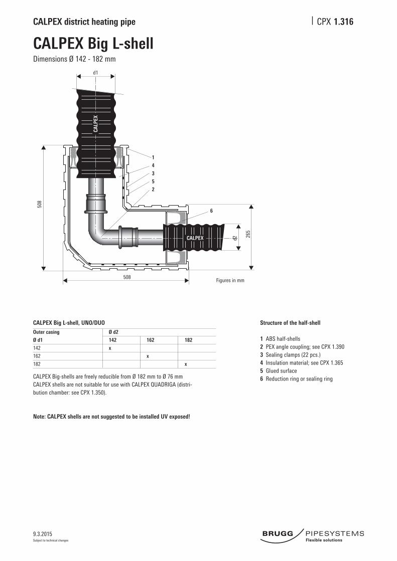
1.316
CALPEX Big L-shellDimensions Ø 142 - 182 mm
Structure of the half-shell
1 ABS half-shells2 PEX angle coupling; see CPX 1.390 3 Sealing clamps (22 pcs.)4 Insulation material; see CPX 1.3655 Glued surface6 Reduction ring or sealing ring
Figures in mm
CALPEX Big-shells are freely reducible from Ø 182 mm to Ø 76 mmCALPEX shells are not suitable for use with CALPEX QUADRIGA (distri-bution chamber: see CPX 1.350).
Note: CALPEX shells are not suggested to be installed UV exposed!
CALPEX Big L-shell, UNO/DUO
Outer casing Ø d2
Ø d1 142 162 182
142 x
162 x
182 x
CALP
EX
CALPEX
d1
1
4
3
5
2
6
d2
508
508
d2 265
9.3.2015
CALPEX district heating pipe CPX
Subject to technical changes
CALPEX
CALPEX
CALPEX
CALPEX
CALPEX
1 2 3 4
1 2
d1d1
d1
d2d2
d2
1.320
Joint using PE-HD shrink sleeve
1 PEX coupling; see sheet 1.3902 Insulation material, PUR or PE; see sheet 1.3653 Shrink sleeve pipe4 Shrink hose
Ø d2 76 91 111 126 142 162 182 250
76 x x
91 x x
111 x x
Ø d1 126 x x
142 x x
162 x x
182 x x
250 x
Ø d2 90 110 125 140 160 180 200 225 250 280 315
76 x x x
91 x x x x
111 x x x x
Ø d1 126 x x x x
142 x x x x
162 x x x x x x
182 x x x x x x
250 x x x
CALPEX-CALPEX CALPEX to insulated steel pipe
CALPEX joint
CALPEX reduction joint
CALPEX – Insulated steel pipe
Weld on
Install
Dimensions Ø 76 - 250 mm
Installation note:
Insulated steel pipe
CALPEX
CALPEX
Insulated steel pipe
Insulated steel pipe
1
2
9.3.2015
CALPEX district heating pipe CPX
Subject to technical changes
CALPEX CALPEX
1 4 3 2 5 6
578
d1 d2 185
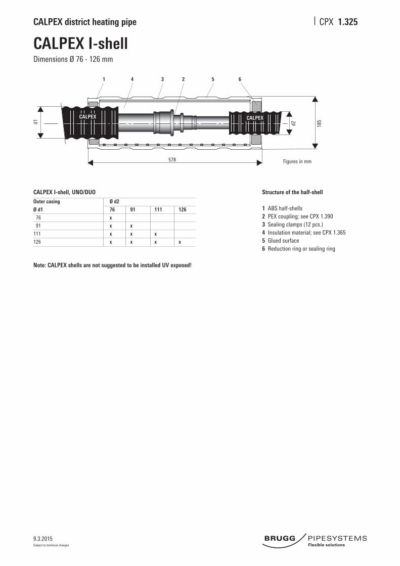
1.325
CALPEX I-shellDimensions Ø 76 - 126 mm
CALPEX I-shell, UNO/DUO
Outer casing Ø d2
Ø d1 76 91 111 126
76 x
91 x x
111 x x x
126 x x x x
Structure of the half-shell
1 ABS half-shells2 PEX coupling; see CPX 1.390 3 Sealing clamps (12 pcs.)4 Insulation material; see CPX 1.3655 Glued surface6 Reduction ring or sealing ring
Figures in mm
Note: CALPEX shells are not suggested to be installed UV exposed!
9.3.2015
CALPEX district heating pipe CPX
Subject to technical changes
CALPEXCALPEX
1 4 3 2 5 6
752
d1 d2 265
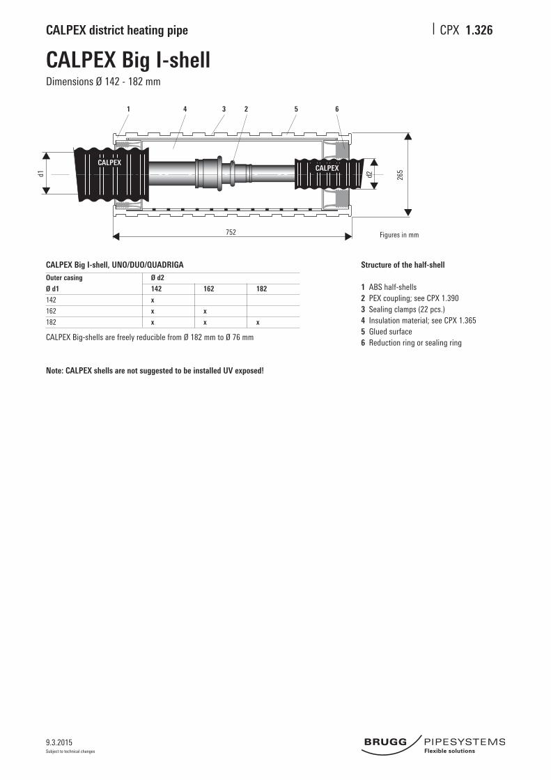
1.326
CALPEX Big I-shellDimensions Ø 142 - 182 mm
Structure of the half-shell
1 ABS half-shells2 PEX coupling; see CPX 1.390 3 Sealing clamps (22 pcs.)4 Insulation material; see CPX 1.3655 Glued surface6 Reduction ring or sealing ring
Figures in mm
CALPEX Big-shells are freely reducible from Ø 182 mm to Ø 76 mm
Note: CALPEX shells are not suggested to be installed UV exposed!
CALPEX Big I-shell, UNO/DUO/QUADRIGA
Outer casing Ø d2
Ø d1 142 162 182
142 x
162 x x
182 x x x
9.3.2015
CALPEX district heating pipe CPX
Subject to technical changes
CALPEX CALPEX
CALP
EX
d2
1
2 5
4
3
6
578
373
d1
d3 185
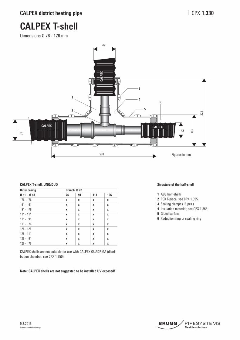
1.330
CALPEX T-shellDimensions Ø 76 - 126 mm
CALPEX T-shell, UNO/DUO
Outer casing Branch, Ø d2
Ø d1 - Ø d3 76 91 111 126
76 - 76 x x x x
91 - 91 x x x x
91 - 76 x x x x
111 - 111 x x x x
111 - 91 x x x x
111 - 76 x x x x
126 - 126 x x x x
126 - 111 x x x x
126 - 91 x x x x
126 - 76 x x x x
Structure of the half-shell
1 ABS half-shells2 PEX T-piece; see CPX 1.395 3 Sealing clamps (16 pcs.)4 Insulation material; see CPX 1.3655 Glued surface6 Reduction ring or sealing ring
CALPEX shells are not suitable for use with CALPEX QUADRIGA (distri-bution chamber: see CPX 1.350).
Note: CALPEX shells are not suggested to be installed UV exposed!
Figures in mm
9.3.2015
CALPEX district heating pipe CPX
Subject to technical changes
752
d2
508
1
6
3
4 52
d1 d3 265
CALPEXCALPEX
CALP
EX
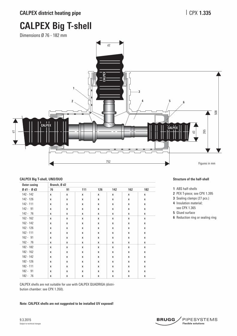
1.335
CALPEX Big T-shellDimensions Ø 76 - 182 mm
CALPEX Big T-shell, UNO/DUO
Outer casing Branch, Ø d2
Ø d1 - Ø d3 76 91 111 126 142 162 182
142 - 142 x x x x x x x
142 - 126 x x x x x x x
142 - 111 x x x x x x x
142 - 91 x x x x x x x
142 - 76 x x x x x x x
162 - 162 x x x x x x x
162 - 142 x x x x x x x
162 - 126 x x x x x x x
162 - 111 x x x x x x x
162 - 91 x x x x x x x
162 - 76 x x x x x x x
182 - 182 x x x x x x x
182 - 162 x x x x x x x
182 - 142 x x x x x x x
182 - 126 x x x x x x x
182 - 111 x x x x x x x
182 - 91 x x x x x x x
182 - 76 x x x x x x x
Structure of the half-shell
1 ABS half-shells2 PEX T-piece; see CPX 1.395 3 Sealing clamps (27 pcs.)4 Insulation material; see CPX 1.3655 Glued surface6 Reduction ring or sealing ring
CALPEX shells are not suitable for use with CALPEX QUADRIGA (distri-bution chamber: see CPX 1.350).
Note: CALPEX shells are not suggested to be installed UV exposed!
UNO pipes KMR Ø D DUO steel pipe X DUO CPX pipe Ø C
mm mm mm mm mm mm
26.9-110 110 26.9+26.9/110 19 25+25/91 110
33.7-110 110 33.7+33.7/110 19 32+32/111 110
42.4-125 125 42.4+42.4/125 19 40+40/126 125
48.3-125 125 48.3+48.3/160 19 50+50/162 160
60.3-140 140 60.3+60.3/180 20 63+63/182 180
1.345
Y-pipeHeating, 6 bar
CALPEX DUO / 2 x CALPEX UNO
CALPEX DUO / 2 x pre-insulated steel pipe (St 37.0)
UNO pipes Ø D DUO CPX pipe Ø C
mm mm mm mm
2x25/76 75 25+25/91 90
2x25/91PLUS 90 25+25/111 110
2x32/76 75 32+32/111 110
2x32/91PLUS 90 32+32/126 125
2x40/91 90 40+40/126 125
2x40/111PLUS 110 40+40/142 140
2x50/111 110 50+50/162 160
2x50/126PLUS 125 50+50/182 180
2x63/126 125 63+63/182 180
2x63/142PLUS 140 63+63/202 200
View: A - A
Note: With UNO pipe, in the direction of
flow,theforwardflow(VL)isalwayson
the right and with DUO pipe, it is always
at the bottom.
View: A - A
Note: With UNO pipe, in the direction of
flow,theforwardflow(VL)isalwayson
the right and with DUO pipe, it is always
at the bottom.
CPX UNO
CPX UNO RL (return)
VL(flow)(right)
RL return
250300250+20250
1800
300
11 0/+1
Figures in mm
mind. 650 VL(flow)(bottom)
[ C
[ D
VL(flow)(right)
KMR
KMR
150400250+20150
1800
300
[ C
Figures in mm
mind. 650X
VL(flow)(bottom)
[ D
VL(flow)(right)VL(flow)(right)
RL (return)
RL (return)
9.3.2015
CALPEX district heating pipe CPX
Subject to technical changes
Distribution chamberDimensions CPX 25/76 - 125/182
Distribution chamber for all joints The distribution chamber is used to cover and protect completed BRUGG pipe joints, shut-off valves or junction branches. The distribution chamber is a watertight structure made of polyethylene; its multi-functional design makes it possible to use one chamber type for all pipe dimensions.
Wallthicknessapprox.8 mm
1.350
Ø Chamber exit Pipe dimensions (outer diameter)
Øouter,206x8mm LeadthroughforouterØ Ø182,162*
Øouter,166x8mm LeadthroughforouterØ Ø142,126*
Øouter,136x8mm LeadthroughforouterØ Ø111,91*,76*
*withadditionalcenteringring
Figures in mm
145
270
130
475
200
8
120120
120360
∅ 800
∅ 206
∅ 166
∅ 136
∅ 1040
9.3.2015
CALPEX district heating pipe CPX
Subject to technical changes
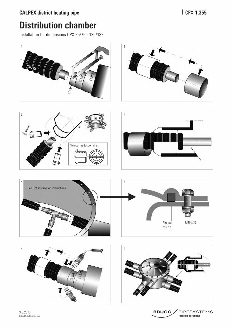
Distribution chamberInstallation for dimensions CPX 25/76 - 125/182
1.355
1 2
3 4
5 6
7 8
Two-part reduction ring
See CPX installation instructions
Flat seal
29x12
M10x35
[ 1
36
[ 1
66
[ 2
06
[ 1
69
[ 2
36
CALPEX
9.3.2015
CALPEX district heating pipe CPX
Subject to technical changes
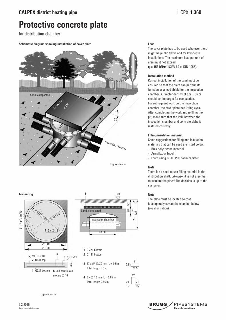
Protective concrete platefor distribution chamber
1.360
Schematic diagram showing installation of cover plate LoadThe cover plate has to be used wherever there mightbepublictrafficandforlow-depthinstallations.Themaximumloadperunitofareamustnotexceedq = 153 kN/m² (SLW 60 to DIN 1055).
Installation method Correct installation of the sand must be ensured so that the plate can perform its function as a load shield for the inspection chamber. A Proctor density of dpr = 96 % should be the target for compaction. For subsequent work on the inspection chamber, the cover plate has lifting eyes. Aftercompletingtheworkandrefillingthepit,makesurethattheinfillbetweentheinspection chamber and concrete slabs is restored correctly.
Filling/insulation materialSomesuggestionsforfillingandinsulationmaterials that can be used are listed below:- Bulk polystyrene material- ArmaflexorTubolit- Foam using BRAG PUR foam canister
NoteThereisnoneedtousefillingmaterialinthedistribution shaft. Likewise, it is not essential to insulate the pipes! The decision is up to the customer.
NoteThe plate must be located so that it completely covers the chamber below (see illustration).
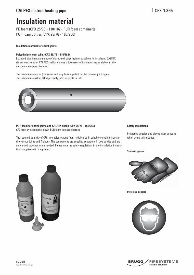
Polyethylene foam tube, (CPX 25/76 - 110/182)Extrudedpipeinsulationmadeofclosed-cellpolyethylene,excellentforinsulatingCALPEXshrinkjoints(notforCALPEXshells).Variousthicknessesofinsulationareavailableforthemost common pipe diameters.
The insulation material (thickness and length) is supplied for the relevant joint types. Theinsulationmustbefittedpreciselyintothejointsonsite.
PUR foam for shrink joints and CALPEX shells (CPX 25/76 - 160/250)CFC-free, cyclopentane-blown PUR foam in plastic bottles
The required quantity of CFC-free polyurethane foam is delivered in suitable container sizes for the various joints and T-pieces. The components are supplied separately in two bottles and are onlymixedtogetherwhenneeded.Pleasenotethesafetyregulationsintheinstallationinstruc-tions supplied with the product.
Safety regulations
Protective goggles and gloves must be wornwhen using this product.
Synthetic gloves
Protective goggles
PE
9.3.2015
CALPEX district heating pipe CPX
Subject to technical changes
L
L
L
L
St 37.0
St 37.0
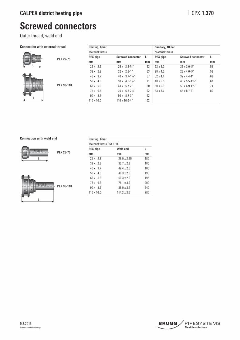
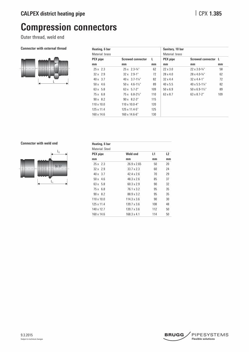
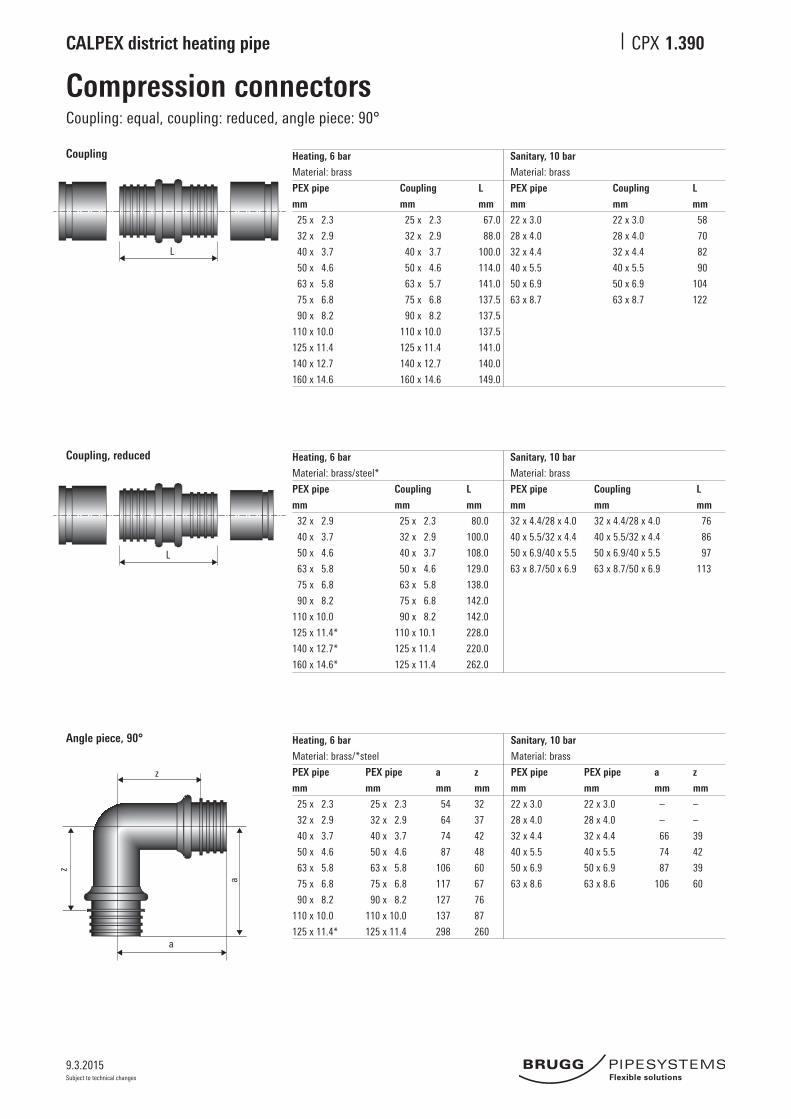
Screwed connectorsOuter thread, weld end
1.370
Connection with external thread Heating, 6 bar Sanitary, 10 bar
Material: brass Material: brass
PEX pipe Screwed connector L PEX pipe Screwed connector L
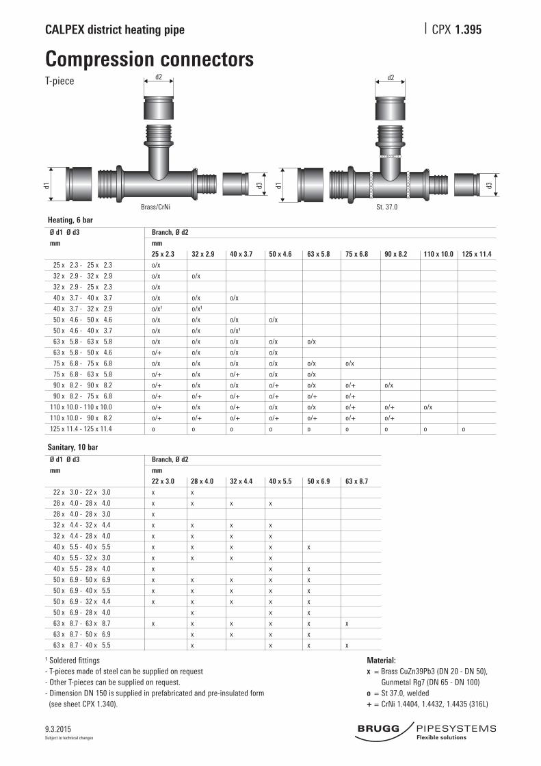
¹Solderedfittings- T-pieces made of steel can be supplied on request- Other T-pieces can be supplied on request. - Dimension DN 150 is supplied in prefabricated and pre-insulated form (see sheet CPX 1.340).
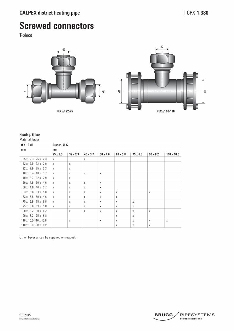
Heating, 6 barØ d1 Ø d3 Branch, Ø d2
mm mm
25 x 2.3 32 x 2.9 40 x 3.7 50 x 4.6 63 x 5.8 75 x 6.8 90 x 8.2 110 x 10.0 125 x 11.4
LD-PE end caps are fitted on; suitable for dry rooms
A A
View A View A
Shrink-on end cap, QUADRIGA End cap, QUADRIGA (LD-PE)
CALPEX UNO
Type Heating Type Sanitary
25/ 76 22/ 76
25/ 91 PLUS 28/ 76
32/ 76 32/ 76
32/ 91 PLUS 32/111 HBK
40/ 91 40/ 91
40/111 PLUS 40/126 HBK
50/111 50/111
50/126 PLUS 50/126 HBK
63/126 63/126
63/142 PLUS
75/142
75/162 PLUS
90/162
90/182 PLUS
110/162
110/182
125/182
125/202 PLUS
140/202
CALPEX DUO
Type
25+25/91
25+25/111PLUS
28+22/91
32+22/111
32+32/111
32+32/126PLUS
40+28/126
40+40/126
40+40/142PLUS
50+32/126
50+50/162
50+50/182PLUS
63+63/182
63+63/202PLUS
QUADRIGA
Type
25+25/28+22/142
32+32/28+22/142
32+32/32+22/142
40+40/40+28/162
9.3.2015
CALPEX district heating pipe CPX
Subject to technical changes
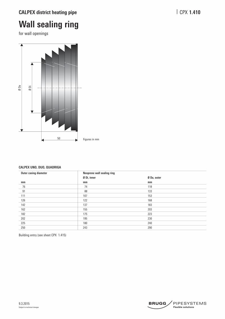
CALPEX UNO, DUO, QUADRIGA
Outer casing diameter Neoprene wall sealing ring
Ø Di, inner Ø Da, outer
mm mm mm
76 74 118
91 88 133
111 107 153
126 122 168
142 137 183
162 155 203
182 175 223
202 195 230
225 180 240
250 243 290
Building entry (see sheet CPX 1.415)
Figures in mm
Wall sealing ringfor wall openings
1.410Ø
Da
Ø Di
50
9.3.2015
CALPEX district heating pipe CPX
Subject to technical changes
80 80100D D
L
H
min. 30
A
D1CALPEX
Building entryWall opening
1.415
Wall leadthrough
Wall opening Outer casing L min H min
Ø D
mm mm mm
78 450 250
93 500 250
113 500 300
128 550 300
143 600 350
163 650 350
183 670 380
202 720 400
225 740 400
250 810 450
PEX connection piece:
see sheet 1.370
or sheet 1.390
End cap:
see sheet 1.405 Wall seal: see sheet 1.410
CALPEX pipe;
see sheets 1.115, 1.120
D
approx.80mm
80 mm
Figures in mm
Core bores Outer casing A D1
Ø D
mm mm mm
78 210 180
93 230 180
113 250 230
128 270 230
143 290 230
163 310 280
183 330 280
202 400 350
225 400 350
250 420 380Figures in mm
9.3.2015
CALPEX district heating pipe CPX
Subject to technical changes
3
4
1
R D
2 3
1
R D
Wall sealCore bores/cement liner pipes
1.420
Standard With additional centering ring
Core bores
Perfect bores are required for installation. As hairline cracks may be present in the concrete or result from drilling, it is advisable to seal the entire length of the borehole with suitable sealant (such as AQUAGARD).
Tightness can only be guaranteed if this recommendation is fol-lowed.
1 CALPEX district heating pipe2 Seal set, single-seal 1x40mm,ShorehardnessD353 Sealset,double-seal* 2x40mm,ShorehardnessD354 Linerpipe:madeoffibrecementorcoatedcorebore
* Suitableforpressurefromwaterupto0.5bar
Outer pipe Liner pipe, core bore Seal set Core bore
Ø R Ø D Ø inner Ø
mm mm mm mm
76 150 78 - 85 150
91 150 86 - 94 150
111 200 105 - 115 200
126 200 125 - 135 200
142 200 137 - 145 200
162 250 157 - 165 250
182 250 180 - 190 250
202 300 198 - 207 300
225 300 225 - 233 300
250 350 250 - 259 350
Building entry (see sheet CPX 1.425)
Oute
r sid
e of
base
men
t
Oute
r sid
e of
base
men
t
Inne
r sid
e of
base
men
t
Inne
r sid
e of
base
men
t
9.3.2015
CALPEX district heating pipe CPX
Subject to technical changes
min. 30
A
D1
CALPEX
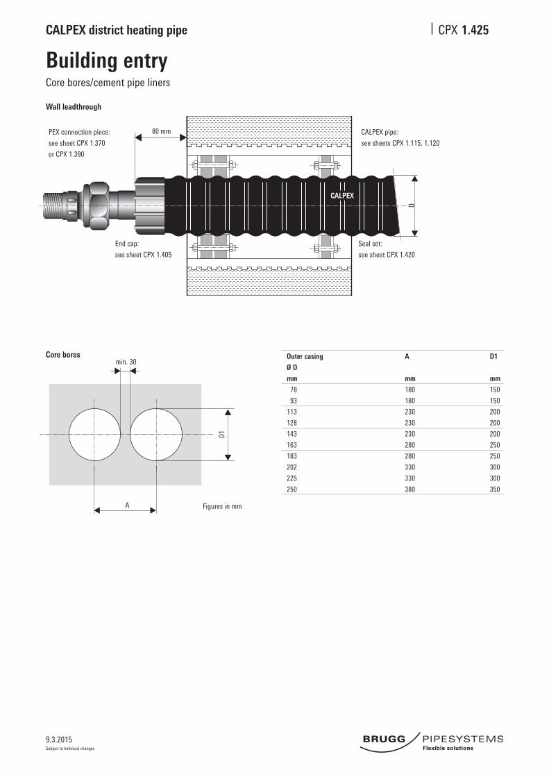
Building entryCore bores/cement pipe liners
1.425
Wall leadthrough
Core bores Outer casing A D1
Ø D
mm mm mm
78 180 150
93 180 150
113 230 200
128 230 200
143 230 200
163 280 250
183 280 250
202 330 300
225 330 300
250 380 350
Figures in mm
PEX connection piece:
see sheet CPX 1.370
or CPX 1.390
End cap:
see sheet CPX 1.405
CALPEX pipe:
see sheets CPX 1.115, 1.120
Seal set:
see sheet CPX 1.420
D
80 mm
9.3.2015
CALPEX district heating pipe CPX
Subject to technical changes
1 2 3
60 3010
D10
T
Pipe warning tape
1.430
CALPEX pipe warning tape
Pipe warning tape to be laid in the ground.Roll length: 250 m
Note: Install the CPX-Clip-Shells according to the installation instruction!
CALPEX®
10UNO DUO y
zx
9
CALPEX
9.3.2015
CALPEX district heating pipe CPX
Subject to technical changes
24 m
m
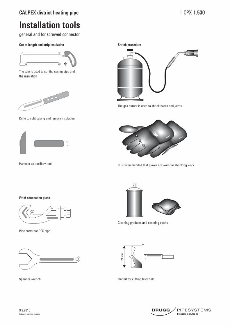
Installation toolsgeneral and for screwed connector
1.530
Cut to length and strip insulation Shrink procedure
It is recommended that gloves are worn for shrinking work. Hammerasauxiliarytool
Fit of connection piece
Pipe cutter for PEX pipe
Spanner wrench Flatbitforcuttingfillerhole
Cleaning products and cleaning cloths
Knife to split casing and remove insulation
The saw is used to cut the casing pipe and the insulation
The gas burner is used to shrink hoses and joints
9.3.2015
CALPEX district heating pipe CPX
Subject to technical changes
Installation toolsforpressfitjoints
1.535
Manual tool for PEX Ø 22 - 40 mm (packed in one case)
Expandertool,uptoØ32mm(basic tool)
Press tool, up to Ø 40 mmExpandertoolforØ40mm(basic tool)
Expanderhead,uptoØ32mm Expanderhead,overØ40mm Press yoke, Ø 22 - 40 mm
Hydraulic tool for PEX Ø 50 - 110 mm (packed in two cases)
Electro-hydraulic tool for PEX Ø 125 - 160 mm (packed in two cases)
HydraulicpressandexpandertoolØ 50 - 110 mm including foot pump (basic tool)
ExpanderheadØ 50 - 110 mm
Press yoke Ø 50, 63 mm
Reducer Ø 75/90 mmfor yoke, Ø 110 mm
HydraulicpressandexpandertoolØ 125 - 160 mm including foot pump (basic tool)
ExpanderheadØ 125 - 160 mm
Press yoke Ø 140 mm, 160 mm
Reducer Ø 125 mmfor yoke, Ø 160 mm
Case with basic toolincluding head and yoke
Case with basic tool(without heads and yoke)
Casewithexpanderheadsand press yoke
Casewithexpanderheadsand press yoke
Case with basic tool(without heads and yoke)
9.3.2015
CALPEX district heating pipe CPX
Subject to technical changes
CALPEX CALPEX CALPEXCALPEX
CALPEX
CALPEX
CALPEX
CALPEX
Heating strip, sanitary, 10 barDrawing in, sensor, joint
1.540
1. Pulling through the heating strip1.Unrollthepipesothatitisstraight,nexttothetrench(withoutbends). See also CPX 1.120. Shorten the casing and cut back the channel.Fromoneend,pushtheglassfibrewire(ø6.5mm)throughthe channel. The heating strip can be pushed in for straight lengths of up to 30 m.
2. Connect the heating strip or pull cord to the wire (drill a hole in the strip) and pull through the heating strip.
4. Joint
Through connection L ≤ Lmax* Feed in from one end
Separate of heating strips L > Lmax*Feedinfrombothend(eachstrip≤Lmax)
Protect the heating strip against moisture* Lmax = max. permitted length for heating strip
The heating strip and the accessories are supplied and installed by the electrician!
2. Installation of the temperature sensor for frost protectionThe temperature sensor has to be installed on the carrier pipe, opposite the heating strip. It must be installed at the coldest point of the pipe (outsidethebuilding).Forthispurpose,cutopenanareaofthecasingmeasuring10x7cmandpeelitoff,cutopen10x7cmoffoam,fixthetemperaturesensorontothecarrierpipewithadhesivetape,filltheholewiththeinsulationmaterialsupplied,applyfillingadhesiveS1113belowand above the temperature sensor cable (see Detail B), and seal with the sealing set.
Glassfibrewire
Heating strip
CALPEX
Temperature sensor cable
Shrink hose Filling adhesive, S 1113, 60 mm long
Shrink hose Temperature sensor
approx.10cm
approx.120mmapprox.7cm
250 mm 300 mm
Heating strip
(HWAT-R; FS-B-2X)
Heating strip joint
(S-06 for HWAT-R and FS-B-2X)
Heating strip
(HWAT-R; FS-B-2X)
End closure
(E-03 for HWAT-R and FS-B-2X)
Shorten the casing by 120 mm and cutofftheexposedchannel.