MAHALAKSHMI ENGINEERING COLLEGE TRICHY-SALEM HIGHWAY, NEAR NO.1 TOLLGATE, THUDAIYUR POST, TIRUCHIRAPPALLI- 621 213 DEPARTMENT OF MECHANICAL ENGINEERING ME 2257 COMPUTER AIDED MACHINE DRAWING LABORATORY MANUAL FOR IV SEMESTER B.E. DEGREE COURSE [REGULATION 2008] PREPARED BY MR. A. BOVAS HERBERT BEJAXHIN AP / MECH
Transcript
MAHALAKSHMI
ENGINEERING COLLEGE
TRICHY-SALEM HIGHWAY, NEAR NO.1 TOLLGATE, THUDAIYUR POST, TIRUCHIRAPPALLI- 621 213
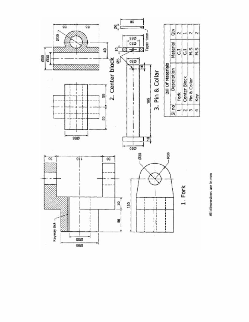
DEPARTMENT OF MECHANICAL ENGINEERING
ME 2257 COMPUTER AIDED MACHINE DRAWING
LABORATORY MANUAL
FOR IV SEMESTER B.E. DEGREE COURSE [REGULATION 2008]
PREPARED BY
MR. A. BOVAS HERBERT BEJAXHIN
AP / MECH
INTRODUCTION
Engineering drawing is the universal graphic language by means of which the
shape and size of an object can be specified on a plane of paper. In order to represent
the true shape and the object, different straight lines are drawn from the various points
on the contour of the object on to the plane of paper. The image or figure, thus, formed
on the paper by joining different points in correct sequence is known as projection of that
object. It is therefore, necessary for an engineer to acquire a good working knowledge of
projections to express and record the shape and size of the object. In this chapter, we
shall deal with the study of projections, types of projections, orthographic projections,
ways of projecting them on drawing, etc.
REVIEW OF ORTHOGONAL AND ISOMETRIC VIEWS: Any object has three dimensions like length, breadth and height. The problem is to
represent or convey all these three dimensions, together with the other details of the
object, on a sheet of drawing paper which has only two dimensions. Orthographic
system of projections is a method of representing the exact shape of a three dimensional
object on a two dimension, sheet in two or more views.
ORTHOGRAPHIC PROJECTION:
It is the projection or view obtained on a plane of projection when the projectors
are parallel to each other, but perpendicular to the plane of projection.
SECTIONAL VIEWS
The orthographic views show the outer details of an object. The inner details like
holes, slots and internal contour are shown by hidden lines. If the hidden lines are too
many, the views become more difficult to understand. In order to make the views more
understandable the object is assumed to be cut by an imaginary plane and the front
portion of the cut object (between the observer and the cutting plane) is removed. Now
the object is viewed and drawn. The exposed or cut surface is drawn by section lining or
cross hatching. The view thus obtained is called as sectional view and the imaginary
plane which cuts the object is called as sectional plane.
NEED FOR SECTIONING:
The sectional views are necessary on the following manners.
1. To show hidden details or internal features of the object
2. To give required additional information about the object
3. To avoid hidden lines
4. To give the clear dimension of hidden details.
5. To make the views more understandable.
SECTION LINES (HATCHING LINES)
When the object is sectioned the cut portions are indicated by using hatching lines.
Section lines a drawn in areas where the cutting plane cuts the material of the object. For easy
understanding assume that the cutting plane is replaced by a sharp knife. Cut the object with
the knife. Now hatch the entire surface where the knife touches the object directly. The other
areas will not be hatched.
Drawing Standards:
1. Welding
Welding is a process of joining metals in which the parent metals are fused together to
form a single piece. Welding is required whenever strength is required. Welding is used
1) As substitute for castings and forgings,
2) As a fabrication medium to join parts permanently and to form builtup members,
3) As a joining medium to replace fasteners such as rivets and bolts
4) As a repair medium to replace broken and worn out sections of a member.
Welding can be classified on the basis of heat source required for welding such as
chemical, which make use of heat by burning fuel, chemical-mechanical welding, Electro-
mechanical welding and electric welding. Of these Electric and Electro-mechanical welding are
widely employed.
Welded joints are classified according to the method of joining such as
6. Butt Joint
7. Lap Joint
8. Strapped Joint
9. Tee Joint
10. Corner Joint
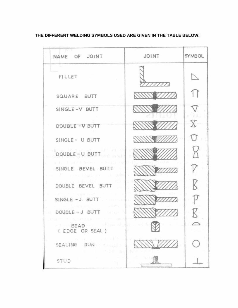
THE DIFFERENT WELDING SYMBOLS USED ARE GIVEN IN THE TABLE BELOW:
2. Keys
The most common function of a key is to prevent relative rotation of a shaft and the
member which is connected to it such as the hub of a gear; pulley or crank. The choice of key to
any installation depends on several factors such as power requirements, tightness of fit, stability
of connection and cost.
1. Types of keys
Square key
Flat key
Taper key
Spline key
Woodruff key
Kennedy key
Round key
Fig (1) Types of Key
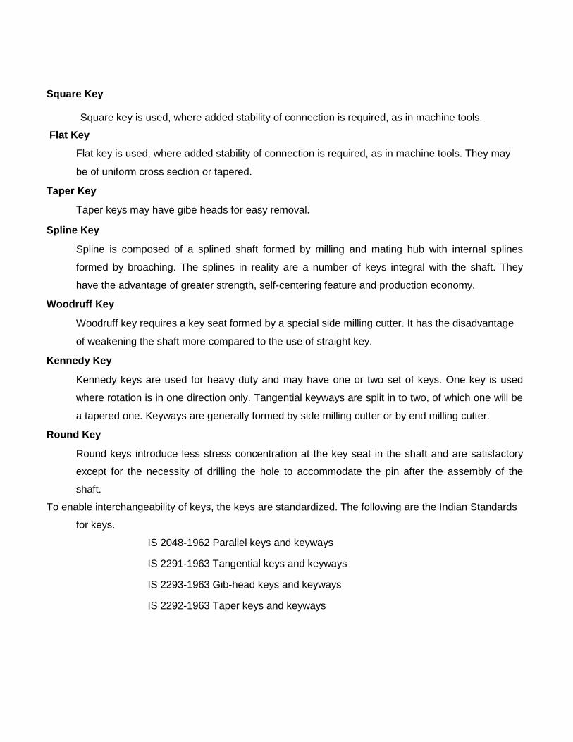
Square Key
Square key is used, where added stability of connection is required, as in machine tools.
Flat Key
Flat key is used, where added stability of connection is required, as in machine tools. They may
be of uniform cross section or tapered. Taper Key
Taper keys may have gibe heads for easy removal. Spline Key
Spline is composed of a splined shaft formed by milling and mating hub with internal splines
formed by broaching. The splines in reality are a number of keys integral with the shaft. They
have the advantage of greater strength, self-centering feature and production economy. Woodruff Key
Woodruff key requires a key seat formed by a special side milling cutter. It has the disadvantage
of weakening the shaft more compared to the use of straight key. Kennedy Key
Kennedy keys are used for heavy duty and may have one or two set of keys. One key is used
where rotation is in one direction only. Tangential keyways are split in to two, of which one will be
a tapered one. Keyways are generally formed by side milling cutter or by end milling cutter. Round Key
Round keys introduce less stress concentration at the key seat in the shaft and are satisfactory
except for the necessity of drilling the hole to accommodate the pin after the assembly of the
shaft.
To enable interchangeability of keys, the keys are standardized. The following are the Indian Standards
for keys.
IS 2048-1962 Parallel keys and keyways
IS 2291-1963 Tangential keys and keyways
IS 2293-1963 Gib-head keys and keyways
IS 2292-1963 Taper keys and keyways
IS 2294-1963 Woodruff keys and keyways
IS 2327-1963 Straight sided splines for general purposes
IS 2610-1964 Straight sided splines for machine tools
IS 3665-1965 Involute sided splines.
3. Riveted Joints
Until recently riveted joints was the main type of permanent joints extensively used in
the construction of pressure vessels, ships, bridges etc. Rapid development of welding
techniques has considerably reduced the sphere of their applications. Riveted joints are
preferable where vibrations are present, since the riveted joints damp out vibrations better than
welded joints and also where weldability of the metals is poor. Riveted joints are widely used
for joining light metals.
The following Indian Standards are preferred for rivets.
1) IS 1928-1961 Boiler rivets.
2) IS 1929-1961 Rivets for general purposes.
3) IS 2907-1964 Non Ferrous rivets.
4) IS 4040-1967 Tubular and semi-tubular rivets.
3.1. Types of Riveted Joints
There are two types of riveted joints:
a) Lap Joint
b) ButtJoint a) Lap Joint
In a lap joint the plate to be connected overlaps each other. When the joint is made with
only one row of rivets, it is called a single-riveted lap joint. A joint is said to be double –riveted
(Fig 2), triple-riveted etc. according to the number of rows of rivets in it. When two or more ows
of rivets are required, rivets may be arranged in i) chain or ii) zigzag
Chain Lap Joint Zigzag Lap Joint
Lap Joint
b) Butt Joint
In a butt joint (Fig 3), edges of the plates to be connected butt against each other and the
joint between them is covered by butt-plates or butt-straps on one or both sides.
Butt Joint
STUDY OF AUTOCAD SOFTWARE
Aim:
To study the drafting software’s AutoCAD.
Cad system:
The CAD system creates an environment to prepare drawings interactively. Most CAD
systems available commercially are menu driven. Commands either can be typed directly with
the help of a keyboard or can be picked-up from the screen menu with the help of a mouse or
can be selected from the digitizer menu. Some screen menus offer pull-down menus (also
referred to as pop-up menu) and dialogue boxes. The effect of every command is immediately
displayed on the screen so that selection and corrections can be done interactively and
immediately.
The major functions to be performed by a Computer Aided Drafting system are:
i. Basic set-up of a drawing
ii. Drawing the objects
iii. Changing the object properties
iv. Translating the objects
v. Scaling the objects
vi. Clipping the objects to fit the image to the screen
vii. Creating symbol libraries for frequently used objects
viii. Text insertion
ix. Dimensioning
Some of the features of CAD system
are:
1) Modeling and Drafting: The majority of systems provide 2D and 3D modeling
capabilities. Some low cost CAD systems are dedicated to 2D drafting only.
2) Ease of use: The users find CAD systems very easy to learn and use.
3) Flexibility: Popular CAD systems provide greater flexibility when configuring the
available hardware. Hundreds of computers, display devices, expansion boards, input and
output devices are compatible and configurable with popular software.
4) Modularity: Standard input and output devices are attached to standard connectors
thereby making the system modular in nature.
5) Low maintenance cost: Little maintenance is needed to keep the system functional.
One of popular, low-cost CAD software is AutoCAD. Some of the fundamentals capabilities of AutoCAD are described here
AutoCAD SOFTWARE:
AutoCAD is a low cost yet very effective Computer Aided Design and drafting software.
AutoCAD is accepted as the industry standard and a large community of CAD users in the world
prefers it. Although AutoCAD is available for a variety of computer systems, majority of
AutoCAD implementations are available on IBM or compatible personal computers with MS-
DOS operating system. AutoCAD comes with very large number of user-selectable options to
support a great variety of commercially available display devices, digitizers, mouse, printers and
plotters. AutoCAD supports 2D drafting and 3D modeling.
The basic drawing entities are lines, polylines of any width, circles, arcs, ellipses and
solids. There are many ways of defining a drawing entity, and the software always prompts the
user for all options. Each drawing entity has an associated line type, color, layer and thickness.
Before any drawing is started, the AutoCAD environment must be prepared for proper
units of measurement, line-type, drawing size, layer, etc. in AutoCAD the drawings are always
prepared at full scale, and the drawing size can be changed at any instant of time by using
LIMITS command.
Drawing entities:
The basic drawing entities of AutoCAD Software are
i. Line v. Polyline
ii. Circle vi. Donut
iii. Arc vii. Polygon
iv. Trace viii. Ellipse
1. Line:
A line is specified by giving its two endpoints. The LINE command can be used to draw
a single line or a series of lines with the end-point of one being the starting point of the next.
When a series of such lines is created, each line is treated as a separate entity. To create a
closed polygon, the user has to type in C (close) for the point: prompt. This causes the last and
the first points to be joined by a line and thus closing of the polygon.
2. Circle:
There are many ways of drawing a circle, the default being the centre point of circle and
radius. Either on typing the command CIRCLE or selecting it from a screen menu with the help
of mouse, all circle drawing options are displayed. The options available are:
Center point and radius
Center point and Diameter
3P: This specifies 3 points on the circumference of a circle. There is a unique circle
passing through three given non-collinear points.
2P: This specifies the end-points of diameter of a circle.
TTR (Tangent Tangent Radius): This command draws a circle of specified radius
that is tangent to two lines, circles or arcs.
3. Arc:
This command is used to draw an arc accurately. Usually there are three parameters
required for drawing an arc. Different ways of drawing circular arcs are:
3 point arc: The arc is drawn by specifying three points on the chord of arc. The first
and third points define the start and end-points of an arc respectively.
Start, Center: This option needs start point and center point of an arc. The third
parameter may be an end-point, included angle, or length of chord.
Start, End: This option asks the user to enter the start and end-points of the arc. The
arc can be completed by either specifying radius or included angle or center point.
4.Trace:
This command is used to draw lines of specified thickness. This is the same as LINE
command except that it needs an additional parameter that is the width or thickness of the line.
5. Pline:
Polylines are interesting drawing entities. Polylines can include both lines and arcs
connected at end-points. Thus, a polyline is a single entity with multiple segments. The polylines
can be straight or curved, can be wide (like a TRACE) or tapered. Fillets and chamfers can be
added where needed on a polyline. Curve fitting and hatching can easily be performed on a
polyline.
6. Donut:
The DONUT is special type of polyline, which is made up of arc segments. A DONUT
has two properties: it has width, and it is closed. The width of DONUT is set by specifying inside
and outside diameters. The inside diameter may be zero thereby making it a filled circle.
7. Polygon:
A polygon is also a polyline with equal length of sides. The regular polygon can either be
inscribed in a circle or circumscribed about the circle. The polygon may also be constructed by
specifying the length of one side and the number of sides of polygon (called edges). In this
method a polygon is constructed in anticlockwise direction from the two edge end points that
have been specified.
8. Ellipse:
An ellipse can be constructed by specifying the center, major and minor axes. An ellipse
can also be constructed by specifying end points of one of its axis and the eccentricity.
Drafting Aids: 1. Layer:
A layer can be thought of as a transparent sheet on which drawings can be prepared.
Drawings can be logically divided into different layers, and layers can be selectively displayed
either individually or in any combination. Each layer is identified by a name. If the drawing
becomes too dense or complicated, some layers can be turned off so that they do not interfere
with the work. The drawing can be edited on any one layer at a time called current layer.
2. Blocks:
The BLOCK command groups a number of selected entities together and treats them as
a single object. If a block is created by using entities on different layers, the entities are stored
inside the block with the entity attributes (colour, layer, and line-type). The block can be created
by using BLOCK command for the same drawing and by WBLOCK command for any other
drawing by giving the name. The block can be reused any number of times in the same drawing
or any other drawing by giving the name. The blocks defined can be scaled, rotated, stretched
or mirrored any number of times. The blocks can be inserted at desired location in the drawing.
3. Dimensioning:
The manufacturing drawing must be dimensioned for size and tolerances so that the
right information can be conveyed. The appearance and size of dimension arrows, size and
style of dimension text with or without tolerances, and the layer on which dimensions are placed
can be controlled by setting dimension variables.
4. Hatch Patterns:
The HATCH command is used to fill up the area using a suitable pattern. The type of
pattern and pattern variables can be chosen from a library of patterns available. The hatching
may be carried out inside a defined area or outside of it.
5. Zoom:
This is the most common method of magnifying a portion of current drawing on the
screen. The portion of drawing to be zoomed is usually selected by a window. A window is
identified by picking up the diagonal corners of a rectangle around the area of interest.
6. Text:
Words, messages and numbers can be inserted as required on an engineering drawing.
The alphanumeric keyboard is used extensively for non-graphical input such as text. The text
style, height, text angle, aspect ratio, colour etc are some of the attributes associated with text.
Editing:
The fundamental commands to edit a drawing are
1. Move: Moves selected objects to another location,
2. Rotate: Rotates selected objects through a specified angle about a base point.
3. Copy: Creates one or more copies of selected objects at another location. The function of
COPY command is similar to the MOVE command except that it preserves a copy of
the objects selected at the original location.
4. Mirror: Creates a mirror image of the selected objects about a specified line.
5. Array: This command creates multiple copies of selected objects in rectangular or polar form.
This is a form of COPY command.
6. Erase: This command deletes the selected entities. A record of entities erased is always
maintained. The most recent entity can be unerased by OOPS command.
7. Oops: This command recovers the last deleted entity. However, it does not recover any entity
after a drawing plotting, end or resume.
8. Break: This command cuts the selected entity in two pieces. Break command is effective on
lines, arcs, circles, traces or polylines (including polygons and donuts)
9. Fillet: The fillet command is used to create a round corner between two lines. The lines are
shortened or extended to fit a tangent arc of specified radius. FILLET works on any
combination of two lines, arcs, circles, non-parallel lines or a single polyline.
10. Chamfer: This command works on two lines or a single polyline to create a beveled edge.
11. Extend: This command extends the lines, polylines and arcs to a boundary edge which can
be a line, polyline, arc or circle. A closed polygon cannot be extended.
12. Offset: This command is useful for creating a parallel copy of a drawing entity which can be
a line, circle or polyline. Each offset creates a new entity with the same line type,
colour and layer settings.
13. Stretch: The stretch Command can either lengthen entities or shorten them and thus alter
their shapes. The center points of arcs or polyline arcs are adjusted accordingly.
14. Trim: This command makes use of boundary entities (lines, arcs, circles or polylines) which
become the cutting edge. It trims lines, arcs, circles and polylines.
15. Scale: The SCALE command allows shrinking or enlarging the already existing drawing
objects by specifying a scale factor.
16. Pedit: polyline is a single entity which is made up of a continuous series of line and arc
segments. The PEDIT command is exclusively used for editing of polyline properties.
The selected line, arc and polyline can be added to an existing polyline by a JOIN
option. A smooth curve passing through all vertices of a polyline can be created by
using FIT option. Similarly, a spline can also be constructed by using polylines
vertices.
17. Explode: This command breaks a polyline into its individual segments. These segments can
then individually be edited and rejoined again to form an edited polyline.
18. Undo: The U or UNDO command reverses the effects of a series of previously used
commands and hence allows back-stepping. The REDO command wipes out the
effect of UNDO command.
Features of AutoCAD:
The advanced features of AutoCAD are
1. Built-in programming language Auto LISP provides programming environment so that
AutoCAD commands can be called along with programs written for computations. This is very
useful for parametric design and drawing.
2. Drawing Exchange Files (DXF) and script files can be used to interface AutoCAD with
programs written in any other higher level language such as C. DXF and IGES file formats allow
the exchange of drawing files among various drafting software’s.
AutoCAD provides techniques to define and extract attributes of entities. This feature is used in
extracting information from a drawing for processing by other programs or to transfer it to a
database
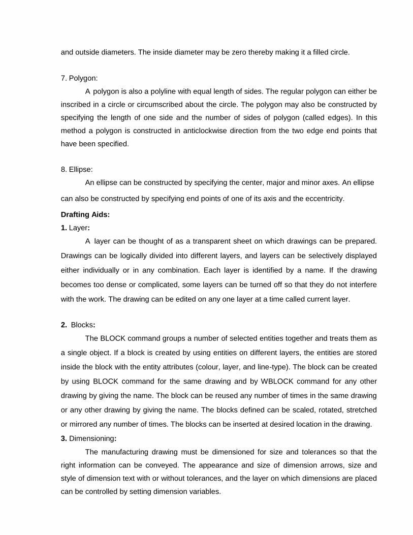
Ex. No: 1 PART DRAWINGS FOR FLANGE COUPLING Date:
Aim:
To draw the part diagrams of the flange coupling and to assemble it using AUTOCAD-