72
CISCO VALIDATED DESIGN REFERENCE NETWORK ARCHITECTURE Campus LAN and Wireless LAN Design Summary October 2015
CISCO VALIDATED DESIGN
REFERENCENETWORK
ARCHITECTURE
Campus LAN and Wireless LAN Design Summary
October 2015
Cisco Validated Design
ContentsCampus Design Introduction ............................................................................................................ 1
Campus LAN and Wireless LAN Design Guidance ........................................................................... 2
High-Density Large Campus Design ................................................................................................................................2
Medium-Density Campus Design .....................................................................................................................................4
Small-Site Campus Design ..............................................................................................................................................5
Campus Wired LAN Design Fundamentals ....................................................................................... 6
Hierarchical Design Model ................................................................................................................................................6
Access Layer ....................................................................................................................................................................8
Distribution Layer ..............................................................................................................................................................9
Core Layer .................................................................................................................................................................... 12
Campus Wired Network Design Options ....................................................................................................................... 13
Campus Wireless LAN Design Fundamentals ................................................................................. 18
Infrastructure ................................................................................................................................................................. 18
Cisco WLAN Controllers ................................................................................................................................................ 19
Wireless Design Models ................................................................................................................................................ 22
Wireless Design Considerations .................................................................................................................................... 28
Multicast Support .......................................................................................................................................................... 31
Band Select ................................................................................................................................................................... 50
ClientLink....................................................................................................................................................................... 51
802.11ac Bandwidth Performance ................................................................................................................................ 53
802.11ac Channel Planning .......................................................................................................................................... 53
Campus Wireless CleanAir ............................................................................................................................................ 55
Detecting Interferers by an Access Point ...................................................................................................................... 57
Secure WLANs .............................................................................................................................................................. 58
Tool to check CUWN (AireOS) 8.1 Best Practices ........................................................................................................ 61
Cisco Validated Design
Common Components in Campus Designs .................................................................................... 62
Device Management Using Cisco Secure ACS ............................................................................................................. 62
Campus Deployment using Cisco Prime Infrastructure ................................................................................................. 62
Meraki Cloud Management ........................................................................................................................................... 64
Campus Quality of Service ............................................................................................................................................ 64
Appendix—Glossary ....................................................................................................................... 66
page 1Cisco Validated Design
Campus Design Introduction
Campus Design IntroductionThere is a tendency to discount the network as just simple plumbing, to think that all you have to consider is the size and the length of the pipes or the speeds and feeds of the links, and to dismiss the rest as unimportant. Just as the plumbing in a large stadium or high rise has to be designed for scale, purpose, redundancy, protection from tampering or denial of operation, and the capacity to handle peak loads, the network requires similar consid-eration. As users depend on the network to access the majority of the information they need to do their jobs and to transport their voice or video with reliability, the network must be able to provide resilient, intelligent transport.
As you look at a network design, consider the networking trends and future needs of an organization.
• The network must be ready to appropriately scale over time in order to meet the demands of the organization it is supporting.
• As demands on wireless access points (APs) with the latest 802.11ac technology exceed 1 Gbps, you should deploy a network that is ready to support the demand without requiring an upgrade of the existing copper Ethernet wiring plant. You accommodate these latest demands by deploying network platforms with mGig capabilities.
• As you deploy new devices with higher power requirements, such as lighting, remote access switches, and APs, your design should have the ability to support power over Ethernet with 60W per port. Cisco Universal Power Over Ethernet (UPOE) in the access achieves this goal.
• Compliance issues drive a choice of platforms required when you support standards certifications and MACsec. For those cases, you should also be prepared to make analytic data available, using technologies such as NetFlow.
• The Internet of Things and Internet of Everything impacts today’s network design. Your network should sup-port TrustSec and other segmentation and virtualization technologies in order to enable the scale and ex-panded uses for the network driven by these trends.
• Bandwidth needs are doubling potentially multiple times over the lifetime of a network so that the network deployed today needs to be prepared to aggregate using 10 Gbps Ethernet to 40 Gbps to 100 Gbps capaci-ties over time.
• The network platforms deployed today should offer the best longevity into the future, versus selecting the equipment that only meets the limits of today’s needs.
• For different site sizes and network densities, you should converge the wired and wireless network platforms when it’s the best way to fit the deployment requirements.
The campus local area network (LAN) is the network that supports devices people use within a location to con-nect to information. The campus LAN can be a single switch at a small remote site up to a large multi-building infrastructure, supporting classrooms, carpeted office space, and similar places where people use their devices. The campus design incorporates both wired and wireless connectivity for a complete network access solution. This document explains:
• The design of the campus wired LAN foundation.
• How the wireless LAN (WLAN) extends secure network access for your mobile workforce.
• How the WLAN can provide guest access for contractors and visitors to your facilities.
For related design guides, deployment guides, and white papers, see the following:
http://www.cisco.com/go/designzone
page 2Cisco Validated Design
Campus LAN and Wireless LAN Design Guidance
Campus LAN and Wireless LAN Design GuidanceDesigning a LAN for the campus use case is not a one-design-fits-all proposition. The scale of campus LAN can be as simple as a single switch and wireless AP at a small remote site or a large, distributed, multi-building complex with high-density wired port and centralized wireless requirements. The deployment may require very high availability for the services offered by the network, with a low tolerance for risk, or there may be tolerance for fix-on-failure approach with extended service outages for a limited number of users considered acceptable. Us-ing a lean cloud-managed approach may be acceptable for some locations, whereas an on-premise IT staff may be preferable for a larger headquarters location with a more concentrated density of network devices. Platform choices for these deployments are often driven by needs for network capacity, the device and network capabili-ties offered, and also the need to meet any compliance requirements that are important to the organization.
Most of the campus wired LAN design complexity is revealed when interconnecting the access and the distribu-tion layers. If devices connecting to the access layer have a requirement for adjacency at Layer 2 and the scale of the network is such that those connections cover multiple wiring closets connected to a distribution layer, then you can adapt the traditional multilayer campus design to address these needs. However, there are preferred alternatives that make the deployment easier to manage and less prone to mistakes. Such alternatives include the simplified distribution layer option using either a switch stack or a virtual switching system (VSS) in the distribu-tion, which makes deployment and troubleshooting much easier for IT staff. You can take this line of simplification even further by deploying a Cisco Catalyst Instant Access Solution, where the access and distribution layers are merged into on device management domain. Even though the traditional multilayer campus design is a widely-deployed valid solution, it is not one that we typically recommend in light of the better alternatives that are avail-able.
The recommended design choices are not the only options available but highlight preferred choices given the scope of the requirements.
HIGH-DENSITY LARGE CAMPUS DESIGNThe high-density large campus design has multiple distribution layers connected to a core and dense demands in the access layer for wired ports and WLAN devices. The preferred design has capacity for supporting over 1000 wired and wireless users and devices, is highly available for critical business continuity, and has the capabilities to support advanced features such NetFlow and network virtualization and segmentation. You may select this design for cases where densities may not be as high as supported; however, the requirements dictate needs for critical business continuity or advanced capabilities.
Campus CoreIf there are three or more interconnected distributions or requirements for connectivity at a common location, you use a Layer 3 LAN core in order to simplify the connectivity and management. You use one of the two core op-tions in order to meet the core needs in the high-density large campus design.
• Catalyst 6800 Series and Catalyst 6500 Series with Supervisor 2T—Family members in the Catalyst Series accommodate a variety of core densities, covering the features commonly used in a campus core. You can merge the devices into a VSS mode, with options for redundant supervisors in each member switch offering a highly available configuration, managed as a single device. This is a preferred option for easy configuration and management, using the most widely deployed core campus platform.
page 3Cisco Validated Design
Campus LAN and Wireless LAN Design Guidance
• Cisco Nexus 7000 Series—Family members in the Cisco Nexus Series have a variety of density options and can be segmented into virtual device contexts, allowing the same devices to be used for a campus core and a data center core. When there are requirements for core switches to be independently managed with the ability to have virtual PortChannels between the switches, or a need for high-density 100 Gigabit Ethernet, these switches are a preferred option.
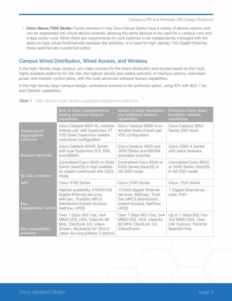
Campus Wired Distribution, Wired Access, and WirelessIn the high-density large campus, you make choices for the wired distribution and access based on the most highly available platforms for the role, the highest density and widest selection of interface options, redundant power and modular control plane, with the most advanced software feature capabilities.
In the high density large campus design, centralized wireless is the preferred option, using APs with 802.11ac and CleanAir capabilities.
Table 1 High-density large campus suggested deployment platforms
Best in Class—comprehensive leading advanced network capabilities
Mission Critical—foundation plus additional network capabilities
Enterprise Class—base foundation network capabilities
Distribution/aggregation switches
Cisco Catalyst 6807-XL modular chassis pair with Supervisor 2T VSS Quad Supervisor stateful switchover configuration
Cisco Catalyst 6880-X ex-tensible fixed chassis pair VSS configuration
Cisco Catalyst 3850 Series SSO stack
Access switches
Cisco Catalyst 4500E Series with dual Supervisor 8-E SSO and 6800IA
Cisco Catalyst 3850 and 3650 Series and 6800IA stackable switches
Cisco 2960-X Series with stack modules
WLAN controller
Centralized Cisco 8500 or 5500 Series (AireOS) in high availabil-ity stateful switchover (HA SSO) mode
Centralized Cisco 8500 or 5500 Series (AireOS) in HA SSO mode
Centralized Cisco 8500 or 5500 Series (AireOS) in HA SSO mode
APs Cisco 3700 Series Cisco 2700 Series Cisco 1700 Series
Key capabilities—wired
Highest availability 1/10/40/100 Gigabit Ethernet services, MACsec, TrustSec MPLS (distribution/Instant Access), NetFlow, UPOE
1/10/40 Gigabit Ethernet services, MACsec, Trust-Sec MPLS (distribution/Instant Access), NetFlow, UPOE
1 Gigabit Ethernet ac-cess, PoE+
Key capabilities—wireless
Over 1 Gbps 802.11ac, 4x4 MIMO:3SS, HDX, CleanAir 80 MHz, ClientLink 3.0, Video-Stream, Modularity for 3G/Lo-cation Accuracy/Wave 2 options
Over 1 Gbps 802.11ac, 3x4 MIMO:3SS, HDX, CleanAir 80 MHz, ClientLink 3.0, VideoStream
Up to 1 Gbps 802.11ac, 3x3 MIMO:2SS, Clea-nAir Express, Transmit Beamforming
page 4Cisco Validated Design
Campus LAN and Wireless LAN Design Guidance
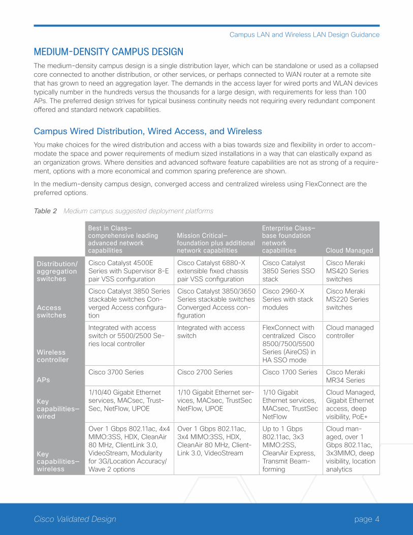
MEDIUM-DENSITY CAMPUS DESIGNThe medium-density campus design is a single distribution layer, which can be standalone or used as a collapsed core connected to another distribution, or other services, or perhaps connected to WAN router at a remote site that has grown to need an aggregation layer. The demands in the access layer for wired ports and WLAN devices typically number in the hundreds versus the thousands for a large design, with requirements for less than 100 APs. The preferred design strives for typical business continuity needs not requiring every redundant component offered and standard network capabilities.
Campus Wired Distribution, Wired Access, and WirelessYou make choices for the wired distribution and access with a bias towards size and flexibility in order to accom-modate the space and power requirements of medium sized installations in a way that can elastically expand as an organization grows. Where densities and advanced software feature capabilities are not as strong of a require-ment, options with a more economical and common sparing preference are shown.
In the medium-density campus design, converged access and centralized wireless using FlexConnect are the preferred options.
Table 2 Medium campus suggested deployment platforms
Best in Class— comprehensive leading advanced network capabilities
Mission Critical—foundation plus additional network capabilities
Enterprise Class—base foundation network capabilities Cloud Managed
Distribution/aggregation switches
Cisco Catalyst 4500E Series with Supervisor 8-E pair VSS configuration
Cisco Catalyst 6880-X extensible fixed chassis pair VSS configuration
Cisco Catalyst 3850 Series SSO stack
Cisco Meraki MS420 Series switches
Access switches
Cisco Catalyst 3850 Series stackable switches Con-verged Access configura-tion
Cisco Catalyst 3850/3650 Series stackable switches Converged Access con-figuration
Cisco 2960-X Series with stack modules
Cisco Meraki MS220 Series switches
Wireless controller
Integrated with access switch or 5500/2500 Se-ries local controller
Integrated with access switch
FlexConnect with centralized Cisco 8500/7500/5500 Series (AireOS) in HA SSO mode
Cloud managed controller
APsCisco 3700 Series Cisco 2700 Series Cisco 1700 Series Cisco Meraki
MR34 Series
Key capabilities—wired
1/10/40 Gigabit Ethernet services, MACsec, Trust-Sec, NetFlow, UPOE
1/10 Gigabit Ethernet ser-vices, MACsec, TrustSec NetFlow, UPOE
1/10 Gigabit Ethernet services, MACsec, TrustSec NetFlow
Cloud Managed, Gigabit Ethernet access, deep visibility, PoE+
Key capabilities—wireless
Over 1 Gbps 802.11ac, 4x4 MIMO:3SS, HDX, CleanAir 80 MHz, ClientLink 3.0, VideoStream, Modularity for 3G/Location Accuracy/Wave 2 options
Over 1 Gbps 802.11ac, 3x4 MIMO:3SS, HDX, CleanAir 80 MHz, Client-Link 3.0, VideoStream
Up to 1 Gbps 802.11ac, 3x3 MIMO:2SS, CleanAir Express, Transmit Beam-forming
Cloud man-aged, over 1 Gbps 802.11ac, 3x3MIMO, deep visibility, location analytics
page 5Cisco Validated Design
Campus LAN and Wireless LAN Design Guidance
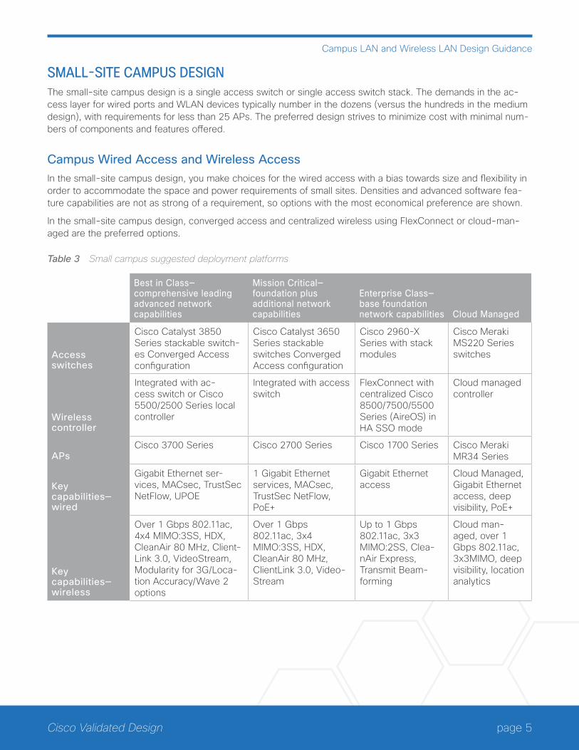
SMALL-SITE CAMPUS DESIGNThe small-site campus design is a single access switch or single access switch stack. The demands in the ac-cess layer for wired ports and WLAN devices typically number in the dozens (versus the hundreds in the medium design), with requirements for less than 25 APs. The preferred design strives to minimize cost with minimal num-bers of components and features offered.
Campus Wired Access and Wireless AccessIn the small-site campus design, you make choices for the wired access with a bias towards size and flexibility in order to accommodate the space and power requirements of small sites. Densities and advanced software fea-ture capabilities are not as strong of a requirement, so options with the most economical preference are shown.
In the small-site campus design, converged access and centralized wireless using FlexConnect or cloud-man-aged are the preferred options.
Table 3 Small campus suggested deployment platforms
Best in Class—comprehensive leading advanced network capabilities
Mission Critical—foundation plus additional network capabilities
Enterprise Class—base foundation network capabilities Cloud Managed
Access switches
Cisco Catalyst 3850 Series stackable switch-es Converged Access configuration
Cisco Catalyst 3650 Series stackable switches Converged Access configuration
Cisco 2960-X Series with stack modules
Cisco Meraki MS220 Series switches
Wireless controller
Integrated with ac-cess switch or Cisco 5500/2500 Series local controller
Integrated with access switch
FlexConnect with centralized Cisco 8500/7500/5500 Series (AireOS) in HA SSO mode
Cloud managed controller
APsCisco 3700 Series Cisco 2700 Series Cisco 1700 Series Cisco Meraki
MR34 Series
Key capabilities—wired
Gigabit Ethernet ser-vices, MACsec, TrustSec NetFlow, UPOE
1 Gigabit Ethernet services, MACsec, TrustSec NetFlow, PoE+
Gigabit Ethernet access
Cloud Managed, Gigabit Ethernet access, deep visibility, PoE+
Key capabilities—wireless
Over 1 Gbps 802.11ac, 4x4 MIMO:3SS, HDX, CleanAir 80 MHz, Client-Link 3.0, VideoStream, Modularity for 3G/Loca-tion Accuracy/Wave 2 options
Over 1 Gbps 802.11ac, 3x4 MIMO:3SS, HDX, CleanAir 80 MHz, ClientLink 3.0, Video-Stream
Up to 1 Gbps 802.11ac, 3x3 MIMO:2SS, Clea-nAir Express, Transmit Beam-forming
Cloud man-aged, over 1 Gbps 802.11ac, 3x3MIMO, deep visibility, location analytics
page 6Cisco Validated Design
Campus Wired LAN Design Fundamentals
Campus Wired LAN Design FundamentalsThe LAN is the networking infrastructure that provides access to network communication services and resources for end users and devices spread over a single floor or building. You create a campus network by interconnect-ing a group of LANs that are spread over a small geographic area. Campus network design concepts are inclusive small networks that use a single LAN switch, up to very large networks with thousands of connections.
The campus wired LAN enables communications between devices in a building or group of buildings, as well as interconnection to the WAN and Internet edge at the network core.
Specifically, this design provides a network foundation and services that enable:
• Tiered LAN connectivity.
• Wired network access for employees.
• IP Multicast for efficient data distribution.
• Wired infrastructure ready for multimedia services.
HIERARCHICAL DESIGN MODELThe campus wired LAN uses a hierarchical design model to break the design up into modular groups or layers. Breaking the design up into layers allows each layer to implement specific functions, which simplifies the network design and therefore the deployment and management of the network.
Modularity in network design allows you to create design elements that can be replicated throughout the network. Replication provides an easy way to scale the network as well as a consistent deployment method.
In flat or meshed network architectures, changes tend to affect a large number of systems. Hierarchical de-sign helps constrain operational changes to a subset of the network, which makes it easy to manage as well as improve resiliency. Modular structuring of the network into small, easy-to-understand elements also facilitates resiliency via improved fault isolation.
A hierarchical LAN design includes the following three layers:
• Access layer—Provides endpoints and users direct access to the network
• Distribution layer—Aggregates access layers and provides connectivity to services
• Core layer—Provides connectivity between distribution layers for large LAN environments
page 7Cisco Validated Design
Campus Wired LAN Design Fundamentals
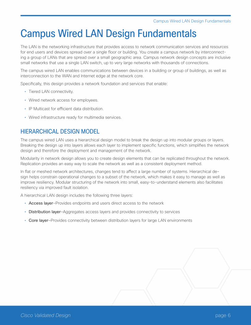
Figure 1 LAN hierarchical design
10
02
FClientAccess
Distribution
Core
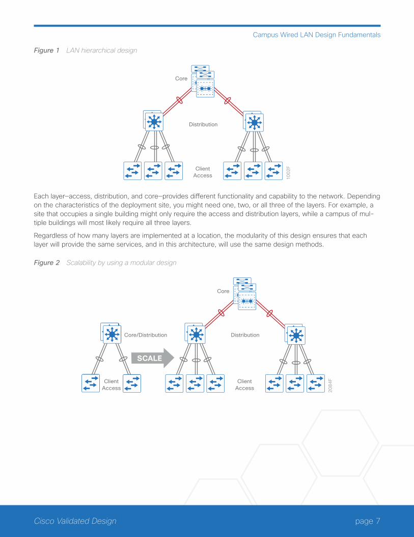
Each layer—access, distribution, and core—provides different functionality and capability to the network. Depending on the characteristics of the deployment site, you might need one, two, or all three of the layers. For example, a site that occupies a single building might only require the access and distribution layers, while a campus of mul-tiple buildings will most likely require all three layers.
Regardless of how many layers are implemented at a location, the modularity of this design ensures that each layer will provide the same services, and in this architecture, will use the same design methods.
Figure 2 Scalability by using a modular design
20
84
FClientAccess
Distribution
Core
Core/Distribution
SCALE
ClientAccess
page 8Cisco Validated Design
Campus Wired LAN Design Fundamentals
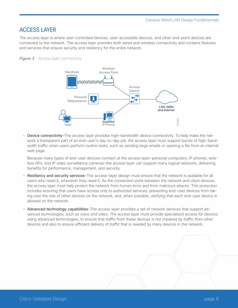
ACCESS LAYERThe access layer is where user-controlled devices, user-accessible devices, and other end-point devices are connected to the network. The access layer provides both wired and wireless connectivity and contains features and services that ensure security and resiliency for the entire network.
Figure 3 Access layer connectivity
20
85
F
AccessSwitch
WirelessAccess Point
PersonalTelepresence
Handheld
IP PhoneUser
LAN, WANand Internet
• Device connectivity—The access layer provides high-bandwidth device connectivity. To help make the net-work a transparent part of an end-user’s day-to-day job, the access layer must support bursts of high-band-width traffic when users perform routine tasks, such as sending large emails or opening a file from an internal web page.
Because many types of end-user devices connect at the access layer—personal computers, IP phones, wire-less APs, and IP video surveillance cameras—the access layer can support many logical networks, delivering benefits for performance, management, and security.
• Resiliency and security services—The access-layer design must ensure that the network is available for all users who need it, whenever they need it. As the connection point between the network and client devices, the access layer must help protect the network from human error and from malicious attacks. This protection includes ensuring that users have access only to authorized services, preventing end-user devices from tak-ing over the role of other devices on the network, and, when possible, verifying that each end-user device is allowed on the network.
• Advanced technology capabilities—The access layer provides a set of network services that support ad-vanced technologies, such as voice and video. The access layer must provide specialized access for devices using advanced technologies, to ensure that traffic from these devices is not impaired by traffic from other devices and also to ensure efficient delivery of traffic that is needed by many devices in the network.
page 9Cisco Validated Design
Campus Wired LAN Design Fundamentals
Access-Layer PlatformsThe preferred options for the campus wired LAN include the following Cisco switches as access-layer platforms:
• Cisco Catalyst 4500E Series Switches
• Cisco Catalyst 3850 Series Switches
• Cisco Catalyst 3650 Series Switches
• Cisco Catalyst 2960-X Series Switches
DISTRIBUTION LAYERThe distribution layer supports many important services. In a network where connectivity needs to traverse the LAN end-to-end, whether between different access layer devices or from an access layer device to the WAN, the distribution layer facilitates this connectivity.
• Scalability—At any site with more than two or three access-layer devices, it is impractical to interconnect all access switches. The distribution layer serves as an aggregation point for multiple access-layer switches.
The distribution layer can lower operating costs by making the network more efficient, by requiring less memory, by creating fault domains that compartmentalize failures or network changes, and by processing resources for devices elsewhere in the network. The distribution layer also increases network availability by containing failures to smaller domains.
• Reduce complexity and increase resiliency—The campus wired LAN has the option to use a simplified dis-tribution layer, in which a distribution-layer node consists of a single logical entity that can be implemented using a pair of physically separate switches operating as one device or using a physical stack of switches operating as one device. Resiliency is provided by physically redundant components like power supplies, supervisors, and modules, as well as stateful switchover to redundant logical control planes.
This approach reduces complexity of configuring and operating the distribution layer because fewer proto-cols are required. Little or no tuning is needed to provide near-second or sub-second convergence around failures or disruptions.
page 10Cisco Validated Design
Campus Wired LAN Design Fundamentals
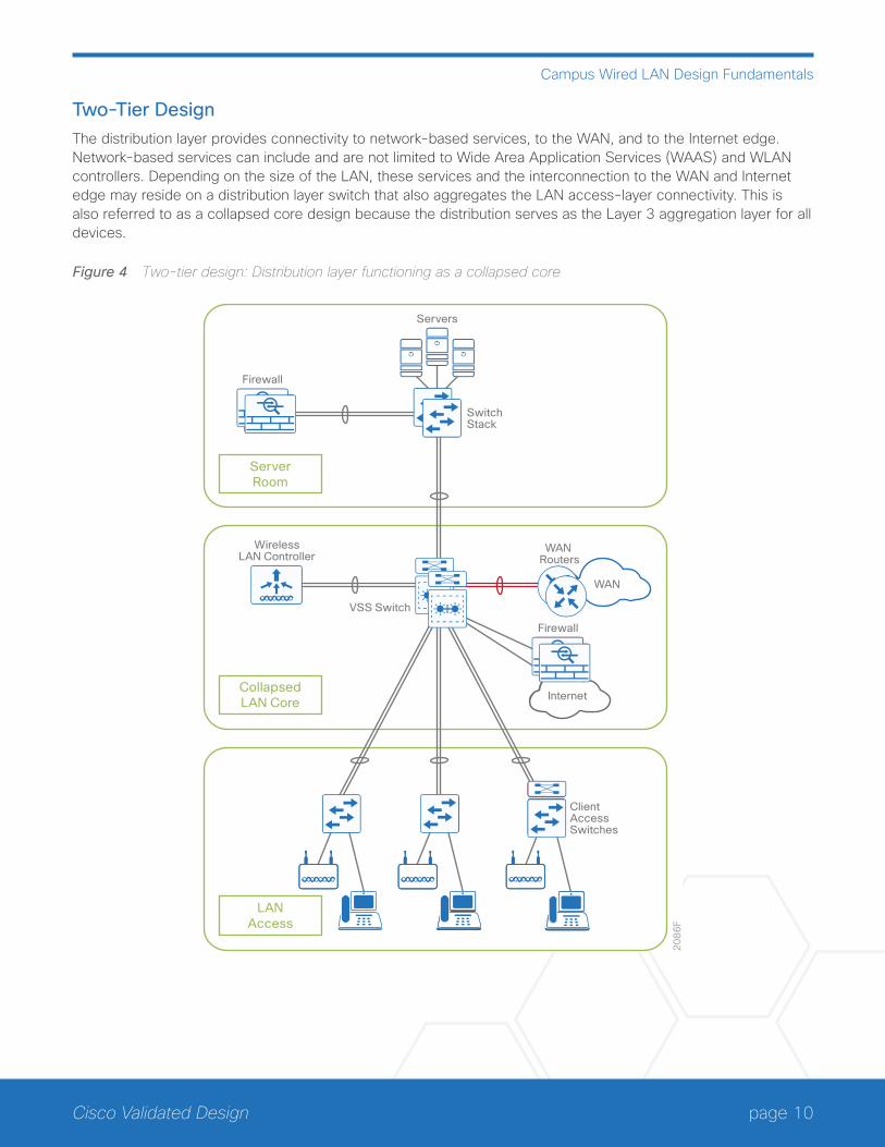
Two-Tier DesignThe distribution layer provides connectivity to network-based services, to the WAN, and to the Internet edge. Network-based services can include and are not limited to Wide Area Application Services (WAAS) and WLAN controllers. Depending on the size of the LAN, these services and the interconnection to the WAN and Internet edge may reside on a distribution layer switch that also aggregates the LAN access-layer connectivity. This is also referred to as a collapsed core design because the distribution serves as the Layer 3 aggregation layer for all devices.
Figure 4 Two-tier design: Distribution layer functioning as a collapsed core
20
86
F
LANAccess
CollapsedLAN Core
ServerRoom
ClientAccessSwitches
VSS Switch
SwitchStack
WirelessLAN Controller
Servers
Firewall
WAN Routers
Firewall
WAN
Internet
page 11Cisco Validated Design
Campus Wired LAN Design Fundamentals
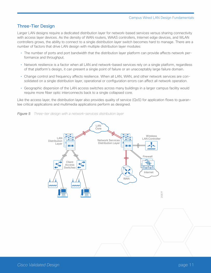
Three-Tier DesignLarger LAN designs require a dedicated distribution layer for network-based services versus sharing connectivity with access layer devices. As the density of WAN routers, WAAS controllers, Internet edge devices, and WLAN controllers grows, the ability to connect to a single distribution layer switch becomes hard to manage. There are a number of factors that drive LAN design with multiple distribution layer modules:
• The number of ports and port bandwidth that the distribution layer platform can provide affects network per-formance and throughput.
• Network resilience is a factor when all LAN and network-based services rely on a single platform, regardless of that platform’s design, it can present a single point of failure or an unacceptably large failure domain.
• Change control and frequency affects resilience. When all LAN, WAN, and other network services are con-solidated on a single distribution layer, operational or configuration errors can affect all network operation.
• Geographic dispersion of the LAN access switches across many buildings in a larger campus facility would require more fiber optic interconnects back to a single collapsed core.
Like the access layer, the distribution layer also provides quality of service (QoS) for application flows to guaran-tee critical applications and multimedia applications perform as designed.
Figure 5 Three-tier design with a network-services distribution layer
20
87
F
LANDistribution
Layer
ClientAccess
Switches
Network ServicesDistribution Layer
WirelessLAN Controller
Firewall
Internet
WAN
LANCore
page 12Cisco Validated Design
Campus Wired LAN Design Fundamentals
Distribution-Layer PlatformsThe preferred Cisco switches for deploying the distribution layer of the campus wired LAN include:
• Cisco Catalyst 6807-XL Series Switches with Supervisor Engine 2T
• Cisco Catalyst 6500 Series Switches with Supervisor Engine 2T
• Cisco Catalyst 6880-X Series Switches
• Cisco Catalyst 4500-X Series Switches
• Cisco Catalyst 4500E Series Switches
• Cisco Catalyst 3850 Series Switches
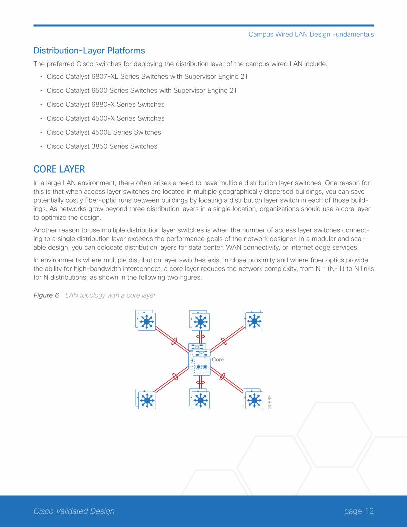
CORE LAYERIn a large LAN environment, there often arises a need to have multiple distribution layer switches. One reason for this is that when access layer switches are located in multiple geographically dispersed buildings, you can save potentially costly fiber-optic runs between buildings by locating a distribution layer switch in each of those build-ings. As networks grow beyond three distribution layers in a single location, organizations should use a core layer to optimize the design.
Another reason to use multiple distribution layer switches is when the number of access layer switches connect-ing to a single distribution layer exceeds the performance goals of the network designer. In a modular and scal-able design, you can colocate distribution layers for data center, WAN connectivity, or Internet edge services.
In environments where multiple distribution layer switches exist in close proximity and where fiber optics provide the ability for high-bandwidth interconnect, a core layer reduces the network complexity, from N * (N-1) to N links for N distributions, as shown in the following two figures.
Figure 6 LAN topology with a core layer
20
88
F
Core
page 13Cisco Validated Design
Campus Wired LAN Design Fundamentals
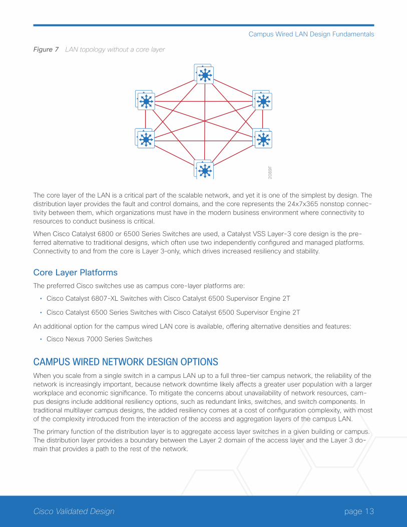
Figure 7 LAN topology without a core layer
20
89
F
The core layer of the LAN is a critical part of the scalable network, and yet it is one of the simplest by design. The distribution layer provides the fault and control domains, and the core represents the 24x7x365 nonstop connec-tivity between them, which organizations must have in the modern business environment where connectivity to resources to conduct business is critical.
When Cisco Catalyst 6800 or 6500 Series Switches are used, a Catalyst VSS Layer-3 core design is the pre-ferred alternative to traditional designs, which often use two independently configured and managed platforms. Connectivity to and from the core is Layer 3–only, which drives increased resiliency and stability.
Core Layer PlatformsThe preferred Cisco switches use as campus core-layer platforms are:
• Cisco Catalyst 6807-XL Switches with Cisco Catalyst 6500 Supervisor Engine 2T
• Cisco Catalyst 6500 Series Switches with Cisco Catalyst 6500 Supervisor Engine 2T
An additional option for the campus wired LAN core is available, offering alternative densities and features:
• Cisco Nexus 7000 Series Switches
CAMPUS WIRED NETWORK DESIGN OPTIONSWhen you scale from a single switch in a campus LAN up to a full three-tier campus network, the reliability of the network is increasingly important, because network downtime likely affects a greater user population with a larger workplace and economic significance. To mitigate the concerns about unavailability of network resources, cam-pus designs include additional resiliency options, such as redundant links, switches, and switch components. In traditional multilayer campus designs, the added resiliency comes at a cost of configuration complexity, with most of the complexity introduced from the interaction of the access and aggregation layers of the campus LAN.
The primary function of the distribution layer is to aggregate access layer switches in a given building or campus. The distribution layer provides a boundary between the Layer 2 domain of the access layer and the Layer 3 do-main that provides a path to the rest of the network.
page 14Cisco Validated Design
Campus Wired LAN Design Fundamentals
This boundary provides two key functions for the LAN. On the Layer 2 side, the distribution layer creates a bound-ary for spanning tree protocol (STP), limiting propagation of Layer 2 faults. On the Layer 3 side, the distribution layer provides a logical point to summarize IP routing information when it enters the network. The summarization reduces IP route tables for easier troubleshooting and reduces protocol overhead for faster recovery from failures.
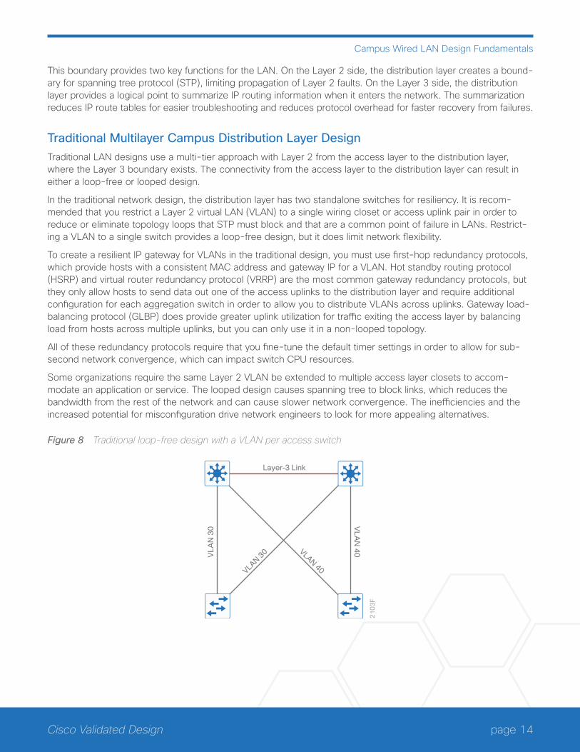
Traditional Multilayer Campus Distribution Layer DesignTraditional LAN designs use a multi-tier approach with Layer 2 from the access layer to the distribution layer, where the Layer 3 boundary exists. The connectivity from the access layer to the distribution layer can result in either a loop-free or looped design.
In the traditional network design, the distribution layer has two standalone switches for resiliency. It is recom-mended that you restrict a Layer 2 virtual LAN (VLAN) to a single wiring closet or access uplink pair in order to reduce or eliminate topology loops that STP must block and that are a common point of failure in LANs. Restrict-ing a VLAN to a single switch provides a loop-free design, but it does limit network flexibility.
To create a resilient IP gateway for VLANs in the traditional design, you must use first-hop redundancy protocols, which provide hosts with a consistent MAC address and gateway IP for a VLAN. Hot standby routing protocol (HSRP) and virtual router redundancy protocol (VRRP) are the most common gateway redundancy protocols, but they only allow hosts to send data out one of the access uplinks to the distribution layer and require additional configuration for each aggregation switch in order to allow you to distribute VLANs across uplinks. Gateway load-balancing protocol (GLBP) does provide greater uplink utilization for traffic exiting the access layer by balancing load from hosts across multiple uplinks, but you can only use it in a non-looped topology.
All of these redundancy protocols require that you fine-tune the default timer settings in order to allow for sub-second network convergence, which can impact switch CPU resources.
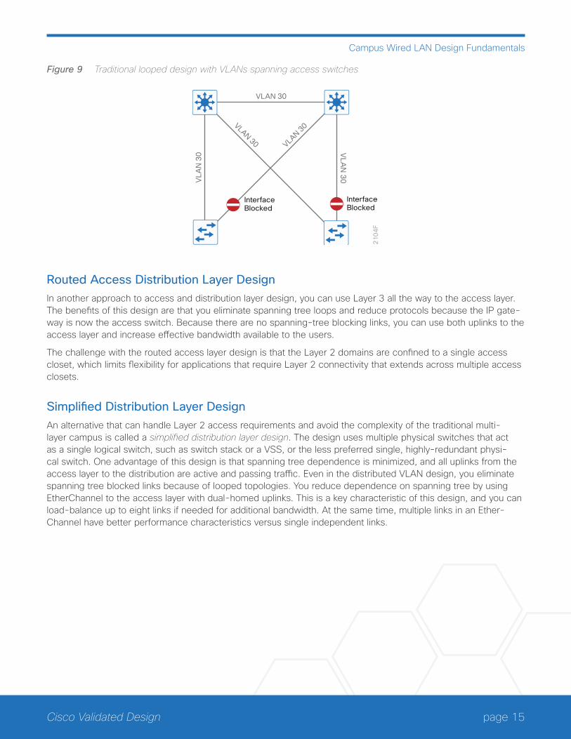
Some organizations require the same Layer 2 VLAN be extended to multiple access layer closets to accom-modate an application or service. The looped design causes spanning tree to block links, which reduces the bandwidth from the rest of the network and can cause slower network convergence. The inefficiencies and the increased potential for misconfiguration drive network engineers to look for more appealing alternatives.
Figure 8 Traditional loop-free design with a VLAN per access switch
21
03
F
Layer-3 Link
VLAN 30 VLAN 40
VLA
N 4
0
VLA
N 3
0
page 15Cisco Validated Design
Campus Wired LAN Design Fundamentals
Figure 9 Traditional looped design with VLANs spanning access switches
21
04
F
VLAN 30
InterfaceBlocked
InterfaceBlocked
VLAN 30VLAN 30
VLA
N 3
0 VLA
N 3
0
Routed Access Distribution Layer DesignIn another approach to access and distribution layer design, you can use Layer 3 all the way to the access layer. The benefits of this design are that you eliminate spanning tree loops and reduce protocols because the IP gate-way is now the access switch. Because there are no spanning-tree blocking links, you can use both uplinks to the access layer and increase effective bandwidth available to the users.
The challenge with the routed access layer design is that the Layer 2 domains are confined to a single access closet, which limits flexibility for applications that require Layer 2 connectivity that extends across multiple access closets.
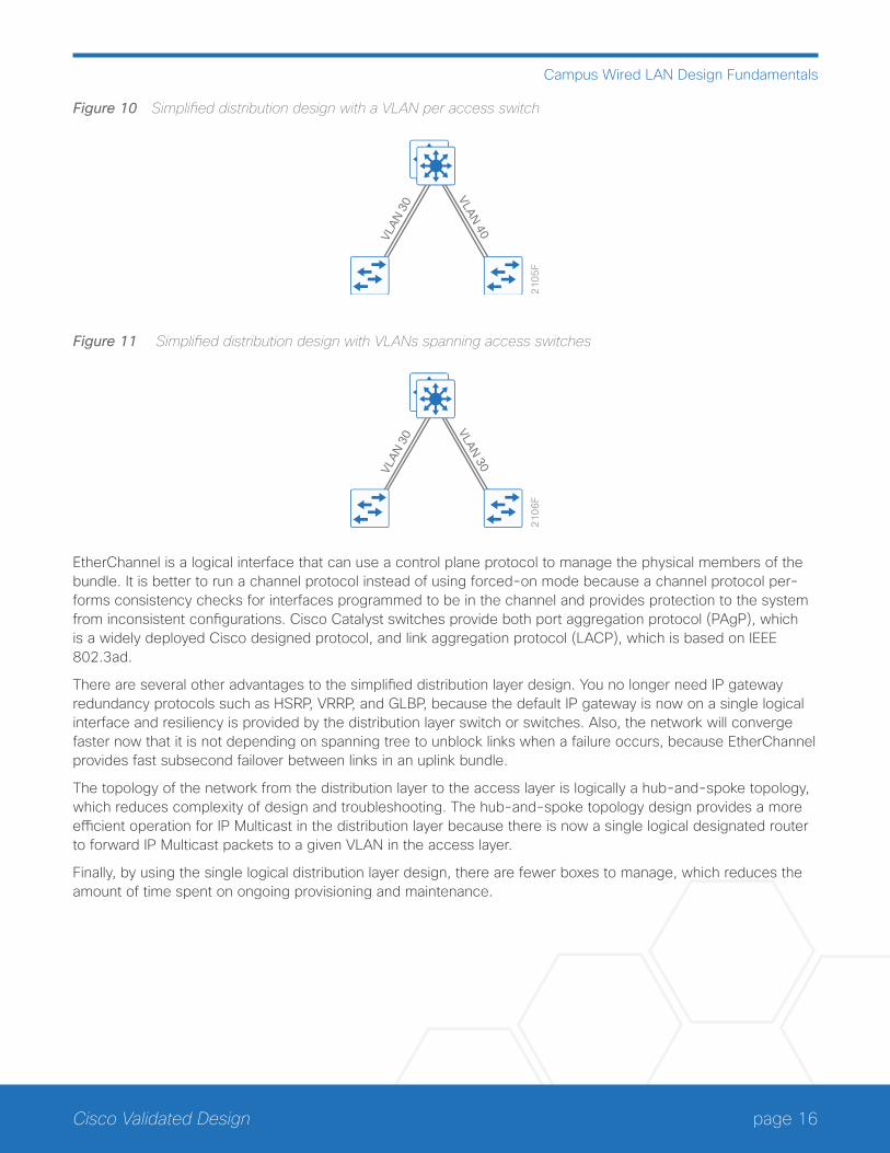
Simplified Distribution Layer DesignAn alternative that can handle Layer 2 access requirements and avoid the complexity of the traditional multi-layer campus is called a simplified distribution layer design. The design uses multiple physical switches that act as a single logical switch, such as switch stack or a VSS, or the less preferred single, highly-redundant physi-cal switch. One advantage of this design is that spanning tree dependence is minimized, and all uplinks from the access layer to the distribution are active and passing traffic. Even in the distributed VLAN design, you eliminate spanning tree blocked links because of looped topologies. You reduce dependence on spanning tree by using EtherChannel to the access layer with dual-homed uplinks. This is a key characteristic of this design, and you can load-balance up to eight links if needed for additional bandwidth. At the same time, multiple links in an Ether-Channel have better performance characteristics versus single independent links.
page 16Cisco Validated Design
Campus Wired LAN Design Fundamentals
Figure 10 Simplified distribution design with a VLAN per access switch
21
05
F
VLA
N 3
0
VLA
N 40
Figure 11 Simplified distribution design with VLANs spanning access switches
21
06
F
VLA
N 3
0
VLA
N 30
EtherChannel is a logical interface that can use a control plane protocol to manage the physical members of the bundle. It is better to run a channel protocol instead of using forced-on mode because a channel protocol per-forms consistency checks for interfaces programmed to be in the channel and provides protection to the system from inconsistent configurations. Cisco Catalyst switches provide both port aggregation protocol (PAgP), which is a widely deployed Cisco designed protocol, and link aggregation protocol (LACP), which is based on IEEE 802.3ad.
There are several other advantages to the simplified distribution layer design. You no longer need IP gateway redundancy protocols such as HSRP, VRRP, and GLBP, because the default IP gateway is now on a single logical interface and resiliency is provided by the distribution layer switch or switches. Also, the network will converge faster now that it is not depending on spanning tree to unblock links when a failure occurs, because EtherChannel provides fast subsecond failover between links in an uplink bundle.
The topology of the network from the distribution layer to the access layer is logically a hub-and-spoke topology, which reduces complexity of design and troubleshooting. The hub-and-spoke topology design provides a more efficient operation for IP Multicast in the distribution layer because there is now a single logical designated router to forward IP Multicast packets to a given VLAN in the access layer.
Finally, by using the single logical distribution layer design, there are fewer boxes to manage, which reduces the amount of time spent on ongoing provisioning and maintenance.
page 17Cisco Validated Design
Campus Wired LAN Design Fundamentals
Instant Access DesignWhen you use Cisco Catalyst 6500 or 6800 Series switches configured as a VSS in the distribution, or as a col-lapsed core and distribution, there is another design option to simplify the network deployment and management further. Ethernet access switches are available to be deployed in an Instant Access role and are connected to the VSS pair. The Instant Access switches initiate communication, which allows them to associate and merge with the VSS distribution to be treated as remote line cards.
In the Instant Access design, all configurations and even software upgrades are invoked by the Instant Access distribution layer, without any need to configure the access ports as a separate switching entity. This option is one of the simplest to configure, because there is no need to manually configure the typical complexities between the access switch devices and the distribution. It also makes features available to the access layer ports that were previously unique to the devices at the distribution layer.
Meraki Cloud Networking for the Wired LANCisco Meraki provides a cloud-based option for deployment of a wired LAN. In the cloud-based architecture, the switches connect through the Internet and are managed through the cloud-based management system. The Meraki controller sits in the public cloud and each corporation gets their own Meraki private cloud to manage. The centralized cloud-based management makes it easier for network administrators to manage their network anytime from anywhere with Internet access.
The components of the Cisco Meraki wired network infrastructure include the following:
• MS220 Layer 2 and MS320 Layer 3 access switches
• MS420 aggregation switches
• Meraki Cloud Management
Similar design methodologies apply for a wired LAN using Cisco Meraki switches. The key difference is using the Cisco Meraki cloud-based management system for day-to-day configuration and management versus using traditional premises-based management. The features and capabilities are not identical to the premises-based offerings, so refer to the online product documentation in order to understand which switches have the features and capabilities that are appropriate for your deployment.
page 18Cisco Validated Design
Campus Wireless LAN Design Fundamentals
Campus Wireless LAN Design FundamentalsThe campus WLAN provides ubiquitous data and voice connectivity for employees, wireless Internet access for guests, and connectivity for Internet of Things devices. Regardless of their location within the organization—on large campuses or at remote sites—wireless users have the same experience when connecting to voice, video, and data services.
The benefits of the campus WLAN include:
• Productivity gains through secure, location-independent network access—Measurable productivity im-provements and communication.
• Additional network flexibility—Hard-to-wire locations connected wirelessly, without costly construction.
• Cost-effective deployment—Adoption of virtualized technologies within the overall wireless architecture.
• Easy to manage and operate—From a single pane of glass, centralized control of a distributed wireless envi-ronment.
• Plug-and-play deployment—Automatic provisioning when an AP is connected to the supporting wired net-work.
• Resilient, fault-tolerant design—Reliable wireless connectivity in mission-critical environments, including complete radio frequency (RF)–spectrum management.
• Support for wireless users—Bring-your-own-device (BYOD) design models.
• Efficient transmission of multicast traffic—Support for many group communication applications, such as video and push-to-talk.
INFRASTRUCTUREThe campus WLAN is built around these main components:
• Cisco WLAN controllers
• Cisco lightweight APs
• Cisco Prime Infrastructure (PI)
• Cisco Mobility Services Engine (MSE)/Cisco Connected Mobile Experiences (CMX)
page 19Cisco Validated Design
Campus Wireless LAN Design Fundamentals
CISCO WLAN CONTROLLERSThe campus WLAN is a controller-based wireless design, which simplifies network management by using Cisco WLAN controllers (WLCs) to centralize the configuration and control of wireless APs. This approach allows the WLAN to operate as an intelligent information network and to support advanced services. The following are some of the benefits of the controller-based design:
• Lower operational expenses—Enables zero-touch configurations for lightweight APs; easy design of channel and power settings and real-time management, including identifying any RF holes in order to optimize the RF environment; seamless mobility across the various APs within the mobility group; and a holistic view of the network, supporting decisions about scale, security, and overall operations.
• Optimized turn-up—Enables streamlined configuration of WLAN controller and overall wireless network through the implementation of best practices during initial WLC configuration.
• Improved return on investment—Enables virtualized instances of the WLAN controller—for only the virtual wireless LAN controller (vWLC)—reducing the total cost of ownership by leveraging their investment in virtual-ization.
• Easier way to scale with optimal design—Enables the network to scale well, by supporting a centralized (lo-cal mode) design for campus environments, and Cisco FlexConnect or Converged Access designs for lean remote sites.
• High availability stateful switchover—Enables non-disruptive connectivity to wireless client devices during a WLAN controller failure.
Cisco WLAN controllers are responsible for system-wide WLAN functions, such as security policies, intrusion prevention, RF management, QoS, and mobility. They work in conjunction with Cisco lightweight APs in order to support business-critical wireless applications. From voice and data services to location tracking, Cisco WLAN controllers provide the control, scalability, security, and reliability that network managers need to build secure, scalable wireless networks.
page 20Cisco Validated Design
Campus Wireless LAN Design Fundamentals
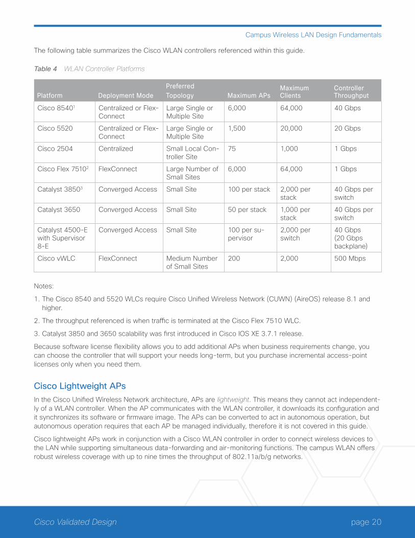
The following table summarizes the Cisco WLAN controllers referenced within this guide.
Table 4 WLAN Controller Platforms
Platform Deployment ModePreferredTopology Maximum APs
Maximum Clients
Controller Throughput
Cisco 85401 Centralized or Flex-Connect
Large Single or Multiple Site
6,000 64,000 40 Gbps
Cisco 5520 Centralized or Flex-Connect
Large Single or Multiple Site
1,500 20,000 20 Gbps
Cisco 2504 Centralized Small Local Con-troller Site
75 1,000 1 Gbps
Cisco Flex 75102 FlexConnect Large Number of Small Sites
6,000 64,000 1 Gbps
Catalyst 38503 Converged Access Small Site 100 per stack 2,000 per stack
40 Gbps per switch
Catalyst 3650 Converged Access Small Site 50 per stack 1,000 per stack
40 Gbps per switch
Catalyst 4500-E with Supervisor 8-E
Converged Access Small Site 100 per su-pervisor
2,000 per switch
40 Gbps (20 Gbps backplane)
Cisco vWLC FlexConnect Medium Number of Small Sites
200 2,000 500 Mbps
Notes:
1. The Cisco 8540 and 5520 WLCs require Cisco Unified Wireless Network (CUWN) (AireOS) release 8.1 and higher.
2. The throughput referenced is when traffic is terminated at the Cisco Flex 7510 WLC.
3. Catalyst 3850 and 3650 scalability was first introduced in Cisco IOS XE 3.7.1 release.
Because software license flexibility allows you to add additional APs when business requirements change, you can choose the controller that will support your needs long-term, but you purchase incremental access-point licenses only when you need them.
Cisco Lightweight APsIn the Cisco Unified Wireless Network architecture, APs are lightweight. This means they cannot act independent-ly of a WLAN controller. When the AP communicates with the WLAN controller, it downloads its configuration and it synchronizes its software or firmware image. The APs can be converted to act in autonomous operation, but autonomous operation requires that each AP be managed individually, therefore it is not covered in this guide.
Cisco lightweight APs work in conjunction with a Cisco WLAN controller in order to connect wireless devices to the LAN while supporting simultaneous data-forwarding and air-monitoring functions. The campus WLAN offers robust wireless coverage with up to nine times the throughput of 802.11a/b/g networks.
page 21Cisco Validated Design
Campus Wireless LAN Design Fundamentals
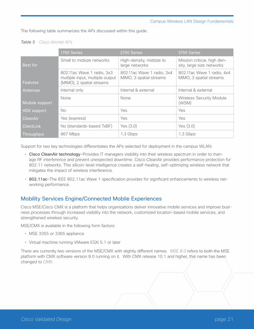
The following table summarizes the APs discussed within this guide.
Table 5 Cisco Aironet APs
1700 Series 2700 Series 3700 Series
Best forSmall to midsize networks High-density, midsize to
large networksMission critical, high den-sity, large size networks
Features
802.11ac Wave 1 radio, 3x3 multiple input, multiple output (MIMO), 2 spatial streams
802.11ac Wave 1 radio, 3x4 MIMO, 3 spatial streams
802.11ac Wave 1 radio, 4x4 MIMO, 3 spatial streams
Antennas Internal only Internal & external Internal & external
Module supportNone None Wireless Security Module
(WSM)
HDX support No Yes Yes
CleanAir Yes (express) Yes Yes
ClientLink No (standards-based TxBF) Yes (3.0) Yes (3.0)
Throughput 867 Mbps 1.3 Gbps 1.3 Gbps
Support for two key technologies differentiates the APs selected for deployment in the campus WLAN:
• Cisco CleanAir technology—Provides IT managers visibility into their wireless spectrum in order to man-age RF interference and prevent unexpected downtime. Cisco CleanAir provides performance protection for 802.11 networks. This silicon-level intelligence creates a self-healing, self-optimizing wireless network that mitigates the impact of wireless interference.
• 802.11ac—The IEEE 802.11ac Wave 1 specification provides for significant enhancements to wireless net-working performance.
Mobility Services Engine/Connected Mobile ExperiencesCisco MSE/Cisco CMX is a platform that helps organizations deliver innovative mobile services and improve busi-ness processes through increased visibility into the network, customized location-based mobile services, and strengthened wireless security.
MSE/CMX is available in the following form factors:
• MSE 3355 or 3365 appliance
• Virtual machine running VMware ESXi 5.1 or later
There are currently two versions of the MSE/CMX with slightly different names. MSE 8.0 refers to both the MSE platform with CMX software version 8.0 running on it. With CMX release 10.1 and higher, this name has been changed to CMX.
page 22Cisco Validated Design
Campus Wireless LAN Design Fundamentals
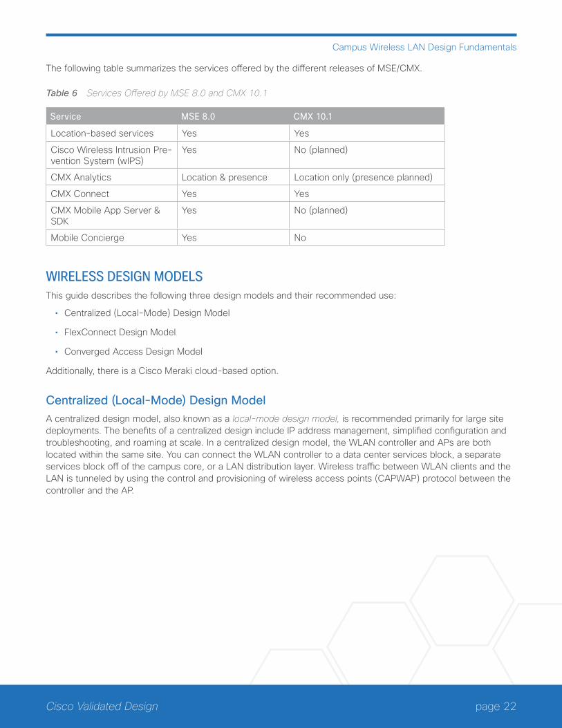
The following table summarizes the services offered by the different releases of MSE/CMX.
Table 6 Services Offered by MSE 8.0 and CMX 10.1
Service MSE 8.0 CMX 10.1
Location-based services Yes Yes
Cisco Wireless Intrusion Pre-vention System (wIPS)
Yes No (planned)
CMX Analytics Location & presence Location only (presence planned)
CMX Connect Yes Yes
CMX Mobile App Server & SDK
Yes No (planned)
Mobile Concierge Yes No
WIRELESS DESIGN MODELSThis guide describes the following three design models and their recommended use:
• Centralized (Local-Mode) Design Model
• FlexConnect Design Model
• Converged Access Design Model
Additionally, there is a Cisco Meraki cloud-based option.
Centralized (Local-Mode) Design Model A centralized design model, also known as a local-mode design model, is recommended primarily for large site deployments. The benefits of a centralized design include IP address management, simplified configuration and troubleshooting, and roaming at scale. In a centralized design model, the WLAN controller and APs are both located within the same site. You can connect the WLAN controller to a data center services block, a separate services block off of the campus core, or a LAN distribution layer. Wireless traffic between WLAN clients and the LAN is tunneled by using the control and provisioning of wireless access points (CAPWAP) protocol between the controller and the AP.
page 23Cisco Validated Design
Campus Wireless LAN Design Fundamentals
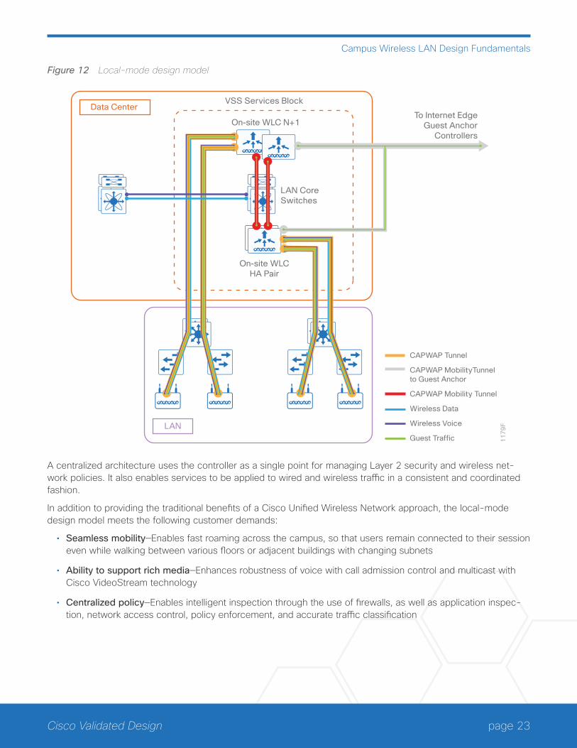
Figure 12 Local-mode design model
11
79
FLAN
VSS Services Block
On-site WLC N+1
LAN CoreSwitches
Data Center
On-site WLCHA Pair
To Internet EdgeGuest Anchor
Controllers
CAPWAP Tunnel
CAPWAP MobilityTunnel to Guest Anchor
CAPWAP Mobility Tunnel
Wireless Data
Wireless Voice
Guest Traffic
A centralized architecture uses the controller as a single point for managing Layer 2 security and wireless net-work policies. It also enables services to be applied to wired and wireless traffic in a consistent and coordinated fashion.
In addition to providing the traditional benefits of a Cisco Unified Wireless Network approach, the local-mode design model meets the following customer demands:
• Seamless mobility—Enables fast roaming across the campus, so that users remain connected to their session even while walking between various floors or adjacent buildings with changing subnets
• Ability to support rich media—Enhances robustness of voice with call admission control and multicast with Cisco VideoStream technology
• Centralized policy—Enables intelligent inspection through the use of firewalls, as well as application inspec-tion, network access control, policy enforcement, and accurate traffic classification
page 24Cisco Validated Design
Campus Wireless LAN Design Fundamentals
If any of the following are true at a site, you should consider deploying a controller locally at the site:
• The site has a data center.
• The site has a LAN distribution layer.
• The site has more than 100 APs.
• The site has a WAN latency greater than 100 ms round-trip to a proposed shared controller.
The recommended platforms for large centralized (local-mode) designs are the Cisco 8540 and 5520 WLAN controllers, due to their scalability and feature support. For smaller sites, you can deploy the Cisco 2504 WLAN controller as a local controller within the site.
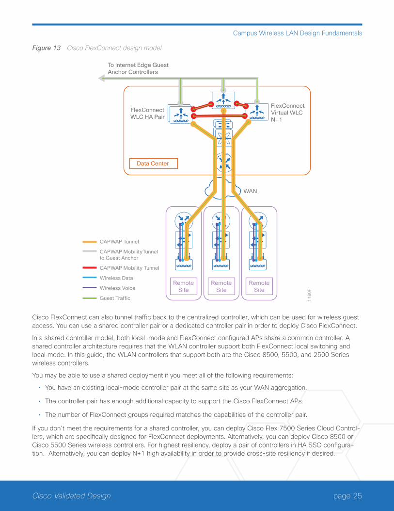
Cisco FlexConnect Design ModelCisco FlexConnect is a wireless solution primarily for deployments that consist of multiple small remote sites (branches) connected into a central site. FlexConnect provides a highly cost effective solution, enabling organi-zations to configure and control remote-site APs from the headquarters through the WAN, without deploying a controller in each remote site. Cisco APs operating in FlexConnect mode can switch client data traffic out their local wired interface and can use 802.1Q trunks in order to segment multiple WLANs. The trunk’s native VLAN is used for all CAPWAP communication between the AP and the controller. This mode of operation is referred to as FlexConnect local switching and is the mode of operation described in this guide.
page 25Cisco Validated Design
Campus Wireless LAN Design Fundamentals
Figure 13 Cisco FlexConnect design model
11
80
F
WAN
RemoteSite
RemoteSite
RemoteSite
FlexConnectWLC HA Pair
FlexConnectVirtual WLCN+1
Data Center
To Internet Edge GuestAnchor Controllers
CAPWAP Tunnel
CAPWAP MobilityTunnel to Guest Anchor
CAPWAP Mobility Tunnel
Wireless Data
Wireless Voice
Guest Traffic
Cisco FlexConnect can also tunnel traffic back to the centralized controller, which can be used for wireless guest access. You can use a shared controller pair or a dedicated controller pair in order to deploy Cisco FlexConnect.
In a shared controller model, both local-mode and FlexConnect configured APs share a common controller. A shared controller architecture requires that the WLAN controller support both FlexConnect local switching and local mode. In this guide, the WLAN controllers that support both are the Cisco 8500, 5500, and 2500 Series wireless controllers.
You may be able to use a shared deployment if you meet all of the following requirements:
• You have an existing local-mode controller pair at the same site as your WAN aggregation.
• The controller pair has enough additional capacity to support the Cisco FlexConnect APs.
• The number of FlexConnect groups required matches the capabilities of the controller pair.
If you don’t meet the requirements for a shared controller, you can deploy Cisco Flex 7500 Series Cloud Control-lers, which are specifically designed for FlexConnect deployments. Alternatively, you can deploy Cisco 8500 or Cisco 5500 Series wireless controllers. For highest resiliency, deploy a pair of controllers in HA SSO configura-tion. Alternatively, you can deploy N+1 high availability in order to provide cross-site resiliency if desired.
page 26Cisco Validated Design
Campus Wireless LAN Design Fundamentals
You can also employ dual resilient controllers configured in an N+1 high availability (HA) model by using the Cisco 2500 series WLAN controller or the Cisco vWLC.
If all of the following are true at a site, you should consider deploying Cisco FlexConnect at the site:
• The site LAN is a single access-layer switch or switch stack.
• The site has fewer than 50 APs.
• The site is one of many small remote sites connected to a central location
• The site has a WAN latency less than 100 ms round-trip to the shared controller.
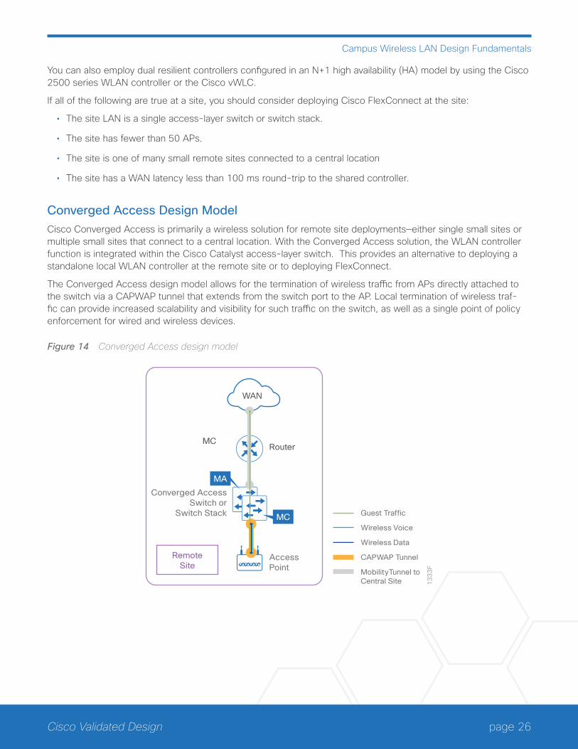
Converged Access Design ModelCisco Converged Access is primarily a wireless solution for remote site deployments—either single small sites or multiple small sites that connect to a central location. With the Converged Access solution, the WLAN controller function is integrated within the Cisco Catalyst access-layer switch. This provides an alternative to deploying a standalone local WLAN controller at the remote site or to deploying FlexConnect.
The Converged Access design model allows for the termination of wireless traffic from APs directly attached to the switch via a CAPWAP tunnel that extends from the switch port to the AP. Local termination of wireless traf-fic can provide increased scalability and visibility for such traffic on the switch, as well as a single point of policy enforcement for wired and wireless devices.
Figure 14 Converged Access design model
RemoteSite
13
33
F
Guest Traffic
Wireless Voice
Wireless Data
CAPWAP Tunnel
MobilityTunnel to Central Site
Router
Converged AccessSwitch or
Switch Stack
MC
MA
MC
AccessPoint
WAN
page 27Cisco Validated Design
Campus Wireless LAN Design Fundamentals
For the Converged Access design model, the Cisco Catalyst 3850 or 3650 Series switch stack—or the Cisco Catalyst 4500 Supervisor Engine 8-E—implements the following wireless controller functionality:
• Mobility Agent—Terminates the CAPWAP tunnels from the APs and maintains the wireless client database.
• Mobility Controller—Manages mobility within and across sub-domains. Also manages radio resource manage-ment (RRM), wIPS, etc.
Up to nine switches are supported in a single switch stack with the Catalyst 3850 and 3650 platforms. The Cata-lyst 4500-E modular switch platform supports wireless integration with the Supervisor 8-E module.
Cisco Meraki Cloud Networking Option for the WLANCisco Meraki provides a cloud-based alternative to the Cisco Unified Wireless Network (CUWN) architecture. In the cloud-based architecture, the APs connect through the Internet to a cloud-based controller for management. This is different from the Cisco FlexConnect model in the sense that the Cisco FlexConnect controller sits in the private data center of the organization, whereas the Meraki controller sits in the public cloud and each corpora-tion gets their own Meraki private cloud to manage. The centralized cloud-based management makes it easier for network administrators to manage their network anytime from anywhere with Internet access.
The components of the Cisco Meraki wireless network infrastructure include the following:
• MR series cloud managed wireless APs
• Meraki cloud management
Cisco Meraki MR Series APs
Cisco Meraki offers a different set of APs that work only with the Cisco Meraki cloud.
Tech Tip
Cisco Aironet APs do not work with the Cisco Meraki cloud-based controller.
The following indoor Cisco Meraki MR Series AP models support 802.11ac:
• The Meraki MR34 is a dual band (5 GHz and 2.4 GHz) 802.11ac AP designed for enterprise environments that require the highest performance and capacity WLAN and the highest density within campus deploy-ments. The MR34 features a 3x3 MIMO design with three spatial streams for a maximum theoretical data rate up to 1.75 Gbps.
• The Meraki MR32 is a dual band (5 GHz and 2.4 GHz), general purpose 802.11ac AP designed for enterprise or retail environments that require a high performance and capacity WLAN and high density within campus deployments. The MR32 features a 2x2 multiple input, MIMO design with two spatial streams for a maximum theoretical data rate up to 1.2 Gbps.
The Meraki MR Series APs discussed above feature a third dual-band radio dedicated to security (WIDS/wIPS) and RF management. The third radio also provides the ability to support data received signal strength (RSSI) for more currency and deterministic location tracking. The MR34 and MR32 also support band steering and beam-forming. The MR32 includes Bluetooth low energy (BLE) beacon scanning capabilities.
page 28Cisco Validated Design
Campus Wireless LAN Design Fundamentals
WIRELESS DESIGN CONSIDERATIONS
High AvailabilityAs more devices with critical functions move to the wireless medium, high availability of the wireless infrastruc-ture is becoming increasingly important. Real-time audio, video, and text communication relies on the corporate wireless network, and the expectation of zero downtime is becoming the norm. The negative impacts of wireless network outages are just as impactful as outages of the wired network. Implementing high availability within the wireless infrastructure involves multiple components and functionality deployed throughout the overall network infrastructure, which itself must be designed for high availability. This section discusses high availability specific to the implementation of wireless controller platforms. Platform-level redundancy refers to the ability to maintain wireless service when connectivity to one or more physical WLAN controller platforms within a site is lost.
The methods of high availability discussed within this design guide are as follows:
• High availability SSO
• N+1 high availability
• Catalyst switch stack resiliency
• WLAN controller link aggregation
High Availability SSO
Cisco AireOS supports access-point stateful switchover and client stateful switchover. These two features are collectively referred to as HA SSO. For both simplicity and efficacy, HA SSO is the preferred option for providing high availability. By using the cost-effective HA SSO licensing model, Cisco wireless deployments can improve the availability of the wireless network with controller recovery times in the sub-second range during a WLAN controller disruption. In addition, HA SSO allows the resilient WLAN controller to be cost-effectively licensed as a standby resilient controller with its access-point license count automatically inherited from its paired primary WLAN controller. This is accomplished by purchasing a standby resilient controller using the HA SKU available for the Cisco 5500, 7500 and 8500 Series WLAN controllers.
The configuration and software upgrades of the primary WLAN controller are automatically synchronized to the resilient standby WLAN controller.
N+1 High Availability
You can use the N+1 HA architecture in order to provide redundancy for WLAN controllers within a single site or across geographically separate sites with lower overall cost of deployment. It is often deployed along with the FlexConnect architecture in order to provide high availability across data centers for remote branches. You can use a single backup WLAN controller in order to provide backup for multiple primary WLAN controllers. HA SSO functionality is not supported for N+1 HA. When the primary controller fails, the AP CAPWAP state machine is restarted.
With N+1 HA, WLAN controllers are independent of each other and do not share configuration or IP addresses on any of their interfaces. Each WLC must be managed separately, can run different hardware, and can be deployed in different datacenters across the WAN link.
page 29Cisco Validated Design
Campus Wireless LAN Design Fundamentals
It is recommended (but not required) that you run the same software version across WLCs used for N+1 HA, in order to reduce down time as the APs establish CAPWAP sessions to the backup controllers. You can config-ure APs with a priority with N+1 HA. APs with high priority on the primary controller always connect first to the backup controller, even if they have to push out low priority APs. When a primary WLC resumes operation, the APs fall back from the backup WLC to the primary WLC automatically, if the AP fallback option is enabled.
You can configure an HA-SKU secondary controller as a backup controller for N+1 HA. The HA-SKU unique device identifier provides the capability of the maximum number of APs supported on that hardware. You cannot configure the N+1 Secondary HA-SKU in combination with HA SSO. They are mutually exclusive
Catalyst Switch Stack Resiliency
Catalyst 3850 and Catalyst 3650 Series switches support StackWise technology along with Cisco IOS software SSO for providing resiliency within a switch stack. Catalyst switch stack resiliency is supported for converged ac-cess switches:
• Catalyst 3850 Series switches—IOS XE software release 3.2.0SE and higher
• Catalyst 3650 Series switches—IOS XE software release 3.3.0SE and higher
Catalyst 3850 Series and Catalyst 3650 Series switches support Cisco StackWise-480 and StackWise-160 stacking ports, respectively. Copper-based Cisco StackWise cabling connects the switches for a stack band-width of approximately 480 Gbps for the Catalyst 3850 Series and 160 Gbps for the Catalyst 3650 Series.
With StackWise technology, the stack of up to nine switches behaves as a single switching unit that is managed by an “active” switch elected by the member switches. The active switch automatically elects a standby switch within the stack. The active switch creates and updates all the switching/routing/wireless information and con-stantly synchronizes that information with the standby switch. If the active switch fails, the standby switch as-sumes the role of the active switch and continues to the keep the stack operational. APs continue to remain con-nected during an active-to-standby switchover. Wireless clients are disassociated and need to re-associate and re-authenticate. Therefore the recovery time is dependent upon how many wireless clients need to be re-asso-ciated and re-authenticated, as well as the method of authentication. No configuration commands are required in order to enable switch stack resiliency on Catalyst 3850 and 3650 Series switches—it is enabled by default when the switches are connected via stack cables.
WLAN Controller Link Aggregation
Most Cisco wireless controller appliances have multiple physical 1 or 10 Gigabit Ethernet ports. In typical de-ployments, one or more WLANs/service set identifiers (SSIDs) are mapped to a dynamic interface, which is then mapped to a physical port. In a centralized design, wireless traffic is backhauled across the network infrastruc-ture and terminated on the physical ports. With the use of a single physical port per WLAN, the throughput of each WLAN is limited to the throughput of the port. Therefore an alternative is to deploy link aggregation (LAG) across the distribution system ports, bundling them into a single high speed interface.
When LAG is enabled, the wireless controller dynamically manages port redundancy and load-balances APs transparently. LAG also simplifies controller configuration because it is no longer necessary to configure primary and secondary ports for each interface. If any of the controller ports fail, traffic is automatically migrated to one of the other ports. As long as at least one controller port is functioning, the wireless controller continues to operate, APs remain connected to the network, and wireless clients continue to send and receive data.
LAG requires an EtherChannel Port Group to be configured on the attached Catalyst switch. The EtherChannel port group can be configured across multiple linecards on the Catalyst switch, or across switches in a Catalyst switch VSS configuration, for additional redundancy. When configured across switches it is referred to as a multi-chassis EtherChannel.
page 30Cisco Validated Design
Campus Wireless LAN Design Fundamentals
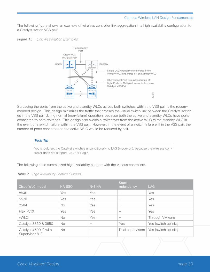
The following figure shows an example of wireless controller link aggregation in a high availability configuration to a Catalyst switch VSS pair.
Figure 15 Link Aggregation Examples
13
34
F
Primary
RedundancyPort
Cisco WLCHA-SSO Pair
Standby
Single LAG Group: Physical Ports 1-4on Primary WLC and Ports 1-4 on Standby WLC
EtherChannel Port Group Consisting of Eight Ports on Multiple Linecards Across aCatalyst VSS Pair
Spreading the ports from the active and standby WLCs across both switches within the VSS pair is the recom-mended design. This design minimizes the traffic that crosses the virtual switch link between the Catalyst switch-es in the VSS pair during normal (non-failure) operation, because both the active and standby WLCs have ports connected to both switches. This design also avoids a switchover from the active WLC to the standby WLC in the event of a switch failure within the VSS pair. However, in the event of a switch failure within the VSS pair, the number of ports connected to the active WLC would be reduced by half.
Tech Tip
You should set the Catalyst switches unconditionally to LAG (mode-on), because the wireless con-troller does not support LACP or PAgP.
The following table summarized high availability support with the various controllers.
Table 7 High Availability Feature Support
Cisco WLC model HA SSO N+1 HAStack redundancy LAG
8540 Yes Yes — Yes
5520 Yes Yes — Yes
2504 No Yes — Yes
Flex 7510 Yes Yes — Yes
vWLC No Yes — Through VMware
Catalyst 3850 & 3650 No — Yes Yes (switch uplinks)
Catalyst 4500-E with Supervisor 8-E
No — Dual supervisors Yes (switch uplinks)
page 31Cisco Validated Design
Campus Wireless LAN Design Fundamentals
MULTICAST SUPPORTVideo and voice applications continue to grow as smartphones, tablets, and PCs are added to wireless networks in all aspects of our daily life. In each of the wireless design models, the multicast support to which users are ac-customed on a wired network is available wirelessly. Multicast is required in order to enable the efficient delivery of certain one-to-many applications, such as video and push-to-talk group communications. By extending the support of multicast beyond that of the campus and data center, mobile users can now use multicast-based ap-plications.
The campus WLAN supports multicast transmission for the onsite controller through the use of multicast-multicast mode, which uses a multicast IP address in order to more efficiently communicate multicast streams to APs that have wireless users subscribing to a particular multicast group. In this guide, multicast-multicast mode is sup-ported by using the Cisco 2500, 5500, and 8500 Series WLAN Controllers.
Remote sites that use the Cisco Flex 7500 Series Cloud Controller or Cisco vWLC using Cisco FlexConnect in local switching mode can also benefit from the use of multicast-based applications. Multicast in remote sites le-verage the underlying WAN and LAN support of multicast traffic. When combined with APs in FlexConnect mode using local switching, subscribers to multicast streams are serviced directly over the WAN or LAN network with no additional overhead being placed on the WLAN controller.
Guest WirelessUsing the existing campus wired and wireless infrastructure for guest access provides a convenient, cost-effec-tive way to offer Internet access for visitors and contractors. The wireless guest network provides the following functionality:
• Provides Internet access to guests through an open wireless SSID, with web authentication access control
• Supports the creation of temporary authentication credentials for each guest by an authorized internal user
• Keeps traffic on the guest network separate from the internal network in order to prevent a guest from ac-cessing internal network resources
• Supports centralized, converged access, and Cisco FlexConnect design models

page 32Cisco Validated Design
Campus Wireless LAN Design Fundamentals
Figure 16 Wireless architecture overview
VSS Services Block
On-site WLCHA Pair
On-siteWLC N+1
WAN
RemoteSite
LAN CoreSwitches
11
78
FRegional Site
Internet Edge Data Center
Internet
Remote SiteWLCs
On-siteWLCs
HA or N+1
Guest Anchor Controller(s)HA or N+1
CAPWAP Tunnel
CAPWAP MobilityTunnel to Guest Anchor
CAPWAP Mobility Tunnel
Wireless Voice
Wireless Data
Guest Traffic
Headquarters
If you have a single controller pair for the entire organization and that controller pair is connected to the same distribution switch as the Internet edge firewall, you can use a shared deployment.
In a shared deployment, a VLAN is created on the distribution switch in order to logically connect guest traffic from the WLAN controllers to the demilitarized zone (DMZ). The DMZ Guest VLAN will not have an associated Layer 3 interface or switch virtual interface. As such, each wireless client on the guest network will use the Inter-net edge firewall as their default gateway.
If you don’t meet the requirements for a shared deployment, you can use Cisco 5500 or Cisco 2500 Series Wireless LAN Controllers in order to deploy a dedicated guest controller. The controller is directly connected the Internet edge DMZ, and guest traffic from every other controller in the organization is tunneled to this controller. Other controllers can provide guest anchoring services as described but are not covered in this guide.
In both the shared and dedicated guest wireless design models, the Internet edge firewall restricts access from the guest network. The guest network is only able to reach the Internet and the internal DHCP and DNS servers.
page 33Cisco Validated Design
Campus Wireless LAN Design Fundamentals
Most organizations’ IT departments choose to have guest wireless users authenticate first, before allowing ac-cess to the Internet. This step is sometimes accompanied with the guest user reading and agreeing to an ac-ceptable use policy (AUP) or end-user agreement (EUA) before accessing the Internet. Since the organization’s IT department typically has no control over the hardware or software capabilities of guest wireless devices, the authentication and authorization decision is often based on only a guest userid and password. In other words, the device with which the guest is accessing the network may not be considered for any policy decision. A typical way of implementing guest user authentication is through the guest user’s web browser, a method known as web authentication or WebAuth. With this method of authentication, the wireless guest must first open his or her web browser, or mobile app with embedded browser, to a URL located somewhere within the Internet. The browser session is re-directed to a web portal that contains a login page that requests login credentials. Upon success-ful authentication, the guest user is either allowed access to the Internet or redirected to another web site. This authentication method is also known as a captive portal.
There are multiple ways of authenticating guests on WLANs, such as the following:
• Local WebAuth—With this method, the web session of the guest device is redirected by the guest wireless controller to a web portal containing the login screen within the guest wireless controller. The guest’s cre-dentials are then checked against the local database within the guest wireless controller. The advantage of this option is that the entire management of guest wireless access is confined to the guest wireless controller within the DMZ. The downside of this option is that guest credentials are maintained separately within the guest wireless controller.
• Central web authentication—With this method, the web session of the guest device is redirected by the guest wireless controller to an external web portal containing the login screen. The guest’s credentials are then checked against an external database within an authentication, authorization, and accounting (AAA) server. Cisco Identity Services Engine (ISE) can provide both the external web portal and AAA server func-tionality. By positioning the WebAuth login portal in a central server, the network administrator can provide one unified login page—with an optional AUP or EUA—for all wireless guest access without having to create a separate login page on each guest wireless controller. By moving the guest credential database and guest sponsor portal to an AAA server, the network administrator can provide one central place for creating and managing guest credentials, versus having to create guest credentials on each guest wireless controller.
• CMX-based guest-onboarding—CMX-based guest-onboarding is often implemented by organizations who wish to provide free Internet access within their venue, in exchange for collecting some information from customers who visit the site. With this method, guests are allowed to use the wireless network and access the Internet from the venue by logging in using their existing social media credentials. The venue owner may also choose to allow anonymous login to the wireless network. The venue owner may also optionally choose to display a splash page and registration form, customized for that particular venue location. You can ac-complish CMX-based guest-onboarding by deploying the Cisco CMX platform (also known as the Mobility Services Engine). You can deploy the Cisco Enterprise Mobility Services Platform along with CMX in order to go beyond simply providing connectivity—by engaging the visitor via a web browser or mobile application deployed on the mobile device.
Cisco OfficeExtendFor the home-based teleworker, it is imperative that access to business services be reliable and consistent, providing an experience that is comparable to being on campus. But on the commonly used 2.4-GHz wireless band, residential and urban environments have many potential sources of congestion, such as cordless hand-sets, smartphones, tablets, and baby monitors. To support users whose technical skills vary widely, a teleworker solution must provide a streamlined and simplified way to implement devices that allow for secure access to the corporate environment.
page 34Cisco Validated Design
Campus Wireless LAN Design Fundamentals
IT operations have a different set of challenges when it comes to implementing a teleworking solution, including properly securing, maintaining, and managing the teleworker environment from a centralized location. Because operational expenses are a constant consideration, IT must implement a cost-effective solution that protects an organization’s investment without sacrificing quality or functionality.
The Cisco OfficeExtend satisfies the ease-of-use, quality-of-experience, and operational-cost requirements. The Cisco OfficeExtend solution is built around two main components:
• Cisco 2500 Series or Cisco 5500 Series or Cisco 8500 Series Wireless LAN Controller
• Cisco Aironet 600 Series OfficeExtend Access Point
Cisco WLAN Controllers
Cisco WLAN controllers work in conjunction with Cisco OfficeExtend APs in order to support business-critical wireless applications for teleworkers. Cisco WLAN controllers provide the control, scalability, security, and reliabil-ity that network managers need to build a secure, scalable teleworker environment.
A standalone controller can support up to 500 Cisco OfficeExtend sites. For a resilient solution, Cisco recom-mends deploying controllers in pairs.
The following controllers are preferred options for Cisco OfficeExtend:
• Cisco 2500 Series Wireless LAN Controller
• Cisco 5500 Series Wireless LAN Controller
Because software license flexibility allows you to add additional APs as business requirements change, you can choose the controller that will support your needs long-term, but you will only pay for what you need, when you need it.
To allow users to connect their endpoint devices to either the organization’s on-site wireless network or their at-home teleworking wireless networks without reconfiguration, Cisco OfficeExtend uses the same wireless SSIDs at teleworkers’ homes as those that support data and voice inside the organization.
Cisco OfficeExtend Access Points
The Cisco Aironet 600 Series OfficeExtend Access Point is lightweight, meaning it cannot act independently of a WLAN controller. To offer remote WLAN connectivity by using the same profile as at the corporate office, the AP validates all traffic against centralized security policies. By using WLAN controllers for the centralization of poli-cies, Cisco OfficeExtend minimizes the management overhead associated with home-based firewalls. A data-gram transport layer security connection secures communications between the AP and the WLAN controller.
Cisco OfficeExtend delivers full 802.11n wireless performance and avoids congestion caused by residential de-vices because it operates simultaneously in the 2.4-GHz and the 5-GHz RF bands. The AP also provides wired Ethernet connectivity in addition to wireless. The Cisco OfficeExtend Access Point provides wired and wireless segmentation of home and corporate traffic, which allows for home device connectivity without introducing secu-rity risks to corporate policy.
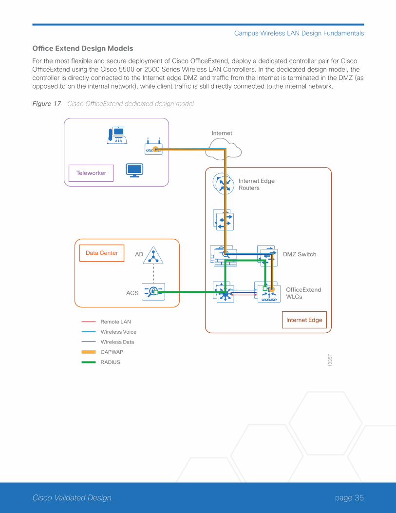
page 35Cisco Validated Design
Campus Wireless LAN Design Fundamentals
Office Extend Design Models
For the most flexible and secure deployment of Cisco OfficeExtend, deploy a dedicated controller pair for Cisco OfficeExtend using the Cisco 5500 or 2500 Series Wireless LAN Controllers. In the dedicated design model, the controller is directly connected to the Internet edge DMZ and traffic from the Internet is terminated in the DMZ (as opposed to on the internal network), while client traffic is still directly connected to the internal network.
Figure 17 Cisco OfficeExtend dedicated design model
Internet EdgeRouters
13
35
F
DMZ Switch
OfficeExtendWLCs
Internet
AD
ACS
Internet Edge
Data Center
Teleworker
Remote LAN
Wireless Voice
Wireless Data
CAPWAP
RADIUS
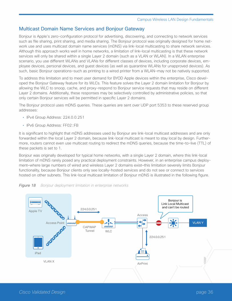
page 36Cisco Validated Design
Campus Wireless LAN Design Fundamentals
Multicast Domain Name Services and Bonjour GatewayBonjour is Apple’s zero-configuration protocol for advertising, discovering, and connecting to network services such as file sharing, print sharing, and media sharing. The Bonjour protocol was originally designed for home net-work use and uses multicast domain name services (mDNS) via link-local multicasting to share network services. Although this approach works well in home networks, a limitation of link-local multicasting is that these network services will only be shared within a single Layer 2 domain (such as a VLAN or WLAN). In a WLAN enterprise scenario, you use different WLANs and VLANs for different classes of devices, including corporate devices, em-ployee devices, personal devices, and guest devices (as well as quarantine WLANs for unapproved devices). As such, basic Bonjour operations—such as printing to a wired printer from a WLAN—may not be natively supported.
To address this limitation and to meet user demand for BYOD Apple devices within the enterprise, Cisco devel-oped the Bonjour Gateway feature for its WLCs. This feature solves the Layer 2 domain limitation for Bonjour by allowing the WLC to snoop, cache, and proxy-respond to Bonjour service requests that may reside on different Layer 2 domains. Additionally, these responses may be selectively controlled by administrative policies, so that only certain Bonjour services will be permitted in specific Layer 2 domains.
The Bonjour protocol uses mDNS queries. These queries are sent over UDP port 5353 to these reserved group addresses:
• IPv4 Group Address: 224.0.0.251
• IPv6 Group Address: FF02::FB
It is significant to highlight that mDNS addresses used by Bonjour are link-local multicast addresses and are only forwarded within the local Layer 2 domain, because link-local multicast is meant to stay local by design. Further-more, routers cannot even use multicast routing to redirect the mDNS queries, because the time-to-live (TTL) of these packets is set to 1.
Bonjour was originally developed for typical home networks, with a single Layer 2 domain, where this link-local limitation of mDNS rarely posed any practical deployment constraints. However, in an enterprise campus deploy-ment—where large numbers of wired and wireless Layer 2 domains exist—this limitation severely limits Bonjour functionality, because Bonjour clients only see locally-hosted services and do not see or connect to services hosted on other subnets. This link-local multicast limitation of Bonjour mDNS is illustrated in the following figure.
Figure 18 Bonjour deployment limitation in enterprise networks
13
36
F
CAPWAP Tunnel
Bonjour is Link Local Multicast and can’t be routed
VLAN X
Access Point
224.0.0.251
WLC
Apple TV
iPad
224.0.0.251
AirPrint
Access
VLAN Y
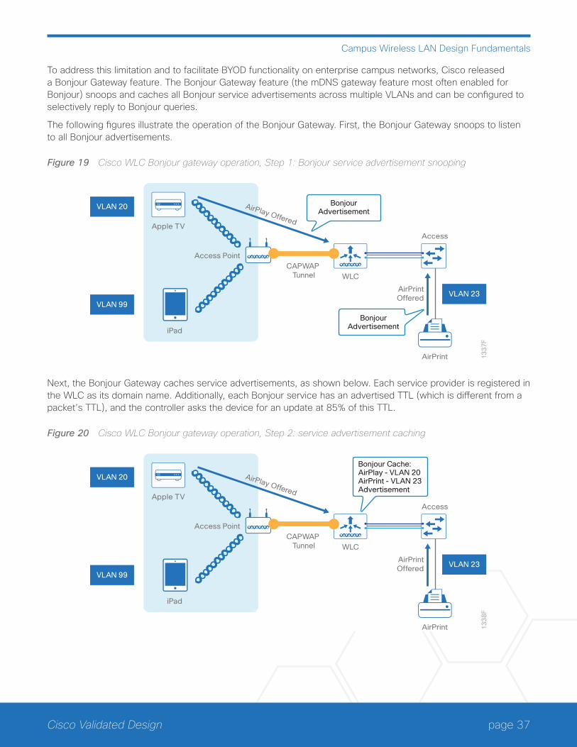
page 37Cisco Validated Design
Campus Wireless LAN Design Fundamentals
To address this limitation and to facilitate BYOD functionality on enterprise campus networks, Cisco released a Bonjour Gateway feature. The Bonjour Gateway feature (the mDNS gateway feature most often enabled for Bonjour) snoops and caches all Bonjour service advertisements across multiple VLANs and can be configured to selectively reply to Bonjour queries.
The following figures illustrate the operation of the Bonjour Gateway. First, the Bonjour Gateway snoops to listen to all Bonjour advertisements.
Figure 19 Cisco WLC Bonjour gateway operation, Step 1: Bonjour service advertisement snooping
VLAN 23
VLAN 20
VLAN 99
13
37
F
CAPWAP Tunnel
BonjourAdvertisement
Access Point
AirPlay Offered
WLC
Apple TV
iPad
AirPrint
Access
BonjourAdvertisement
AirPrintOffered
Next, the Bonjour Gateway caches service advertisements, as shown below. Each service provider is registered in the WLC as its domain name. Additionally, each Bonjour service has an advertised TTL (which is different from a packet’s TTL), and the controller asks the device for an update at 85% of this TTL.
Figure 20 Cisco WLC Bonjour gateway operation, Step 2: service advertisement caching
VLAN 23
VLAN 20
VLAN 99
13
38
F
CAPWAP Tunnel
Bonjour Cache:AirPlay - VLAN 20AirPrint - VLAN 23Advertisement
Access Point
AirPlay Offered
WLC
Apple TV
iPad
AirPrint
Access
AirPrintOffered
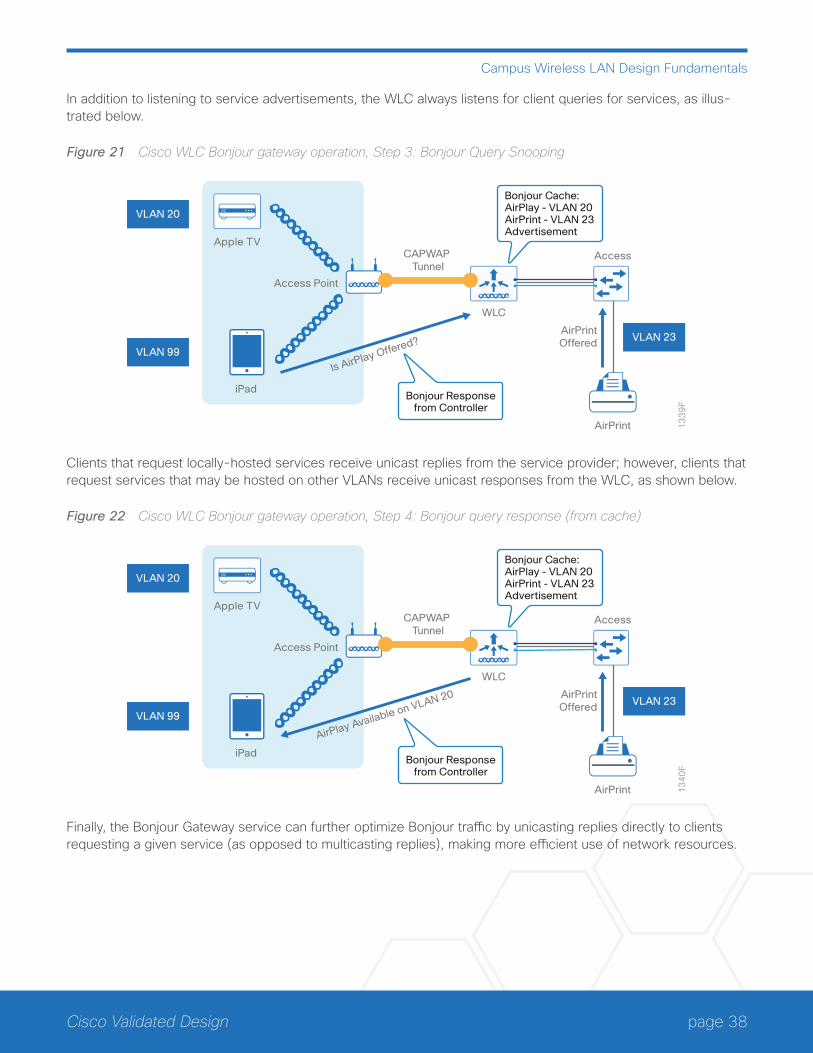
page 38Cisco Validated Design
Campus Wireless LAN Design Fundamentals
In addition to listening to service advertisements, the WLC always listens for client queries for services, as illus-trated below.
Figure 21 Cisco WLC Bonjour gateway operation, Step 3: Bonjour Query Snooping
VLAN 23
VLAN 20
VLAN 99
13
39
F
CAPWAP Tunnel
Bonjour Cache:AirPlay - VLAN 20AirPrint - VLAN 23Advertisement
Access Point
Is AirPlay Offered?
WLC
Apple TV
iPad
AirPrint
Access
AirPrintOffered
Bonjour Responsefrom Controller
Clients that request locally-hosted services receive unicast replies from the service provider; however, clients that request services that may be hosted on other VLANs receive unicast responses from the WLC, as shown below.
Figure 22 Cisco WLC Bonjour gateway operation, Step 4: Bonjour query response (from cache)
VLAN 23
VLAN 20
VLAN 99
13
40
F
CAPWAP Tunnel
Bonjour Cache:AirPlay - VLAN 20AirPrint - VLAN 23Advertisement
Access Point
AirPlay Available on VLAN 20
WLC
Apple TV
iPad
AirPrint
Access
AirPrintOffered
Bonjour Responsefrom Controller
Finally, the Bonjour Gateway service can further optimize Bonjour traffic by unicasting replies directly to clients requesting a given service (as opposed to multicasting replies), making more efficient use of network resources.
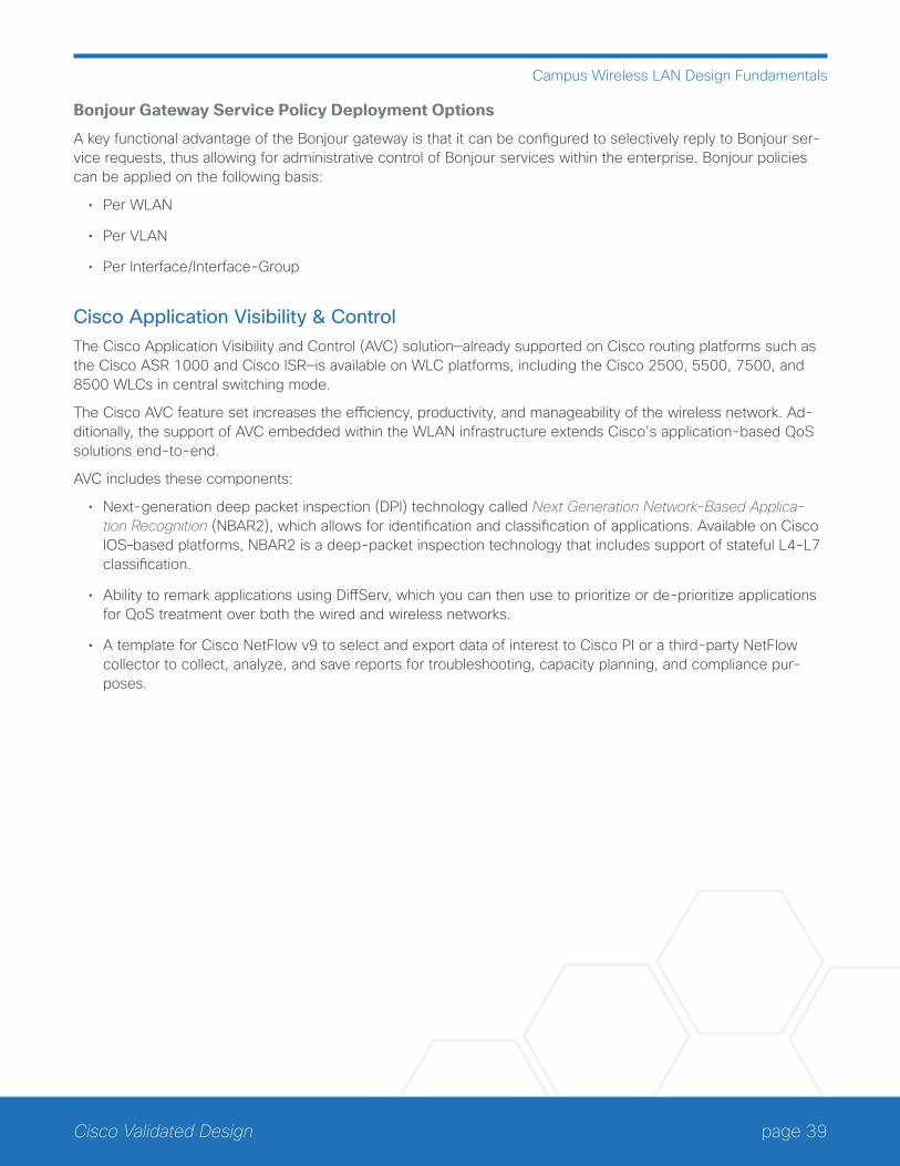
page 39Cisco Validated Design
Campus Wireless LAN Design Fundamentals
Bonjour Gateway Service Policy Deployment Options
A key functional advantage of the Bonjour gateway is that it can be configured to selectively reply to Bonjour ser-vice requests, thus allowing for administrative control of Bonjour services within the enterprise. Bonjour policies can be applied on the following basis:
• Per WLAN
• Per VLAN
• Per Interface/Interface-Group
Cisco Application Visibility & ControlThe Cisco Application Visibility and Control (AVC) solution—already supported on Cisco routing platforms such as the Cisco ASR 1000 and Cisco ISR—is available on WLC platforms, including the Cisco 2500, 5500, 7500, and 8500 WLCs in central switching mode.
The Cisco AVC feature set increases the efficiency, productivity, and manageability of the wireless network. Ad-ditionally, the support of AVC embedded within the WLAN infrastructure extends Cisco’s application-based QoS solutions end-to-end.
AVC includes these components:
• Next-generation deep packet inspection (DPI) technology called Next Generation Network-Based Applica-tion Recognition (NBAR2), which allows for identification and classification of applications. Available on Cisco IOS–based platforms, NBAR2 is a deep-packet inspection technology that includes support of stateful L4-L7 classification.
• Ability to remark applications using DiffServ, which you can then use to prioritize or de-prioritize applications for QoS treatment over both the wired and wireless networks.
• A template for Cisco NetFlow v9 to select and export data of interest to Cisco PI or a third-party NetFlow collector to collect, analyze, and save reports for troubleshooting, capacity planning, and compliance pur-poses.
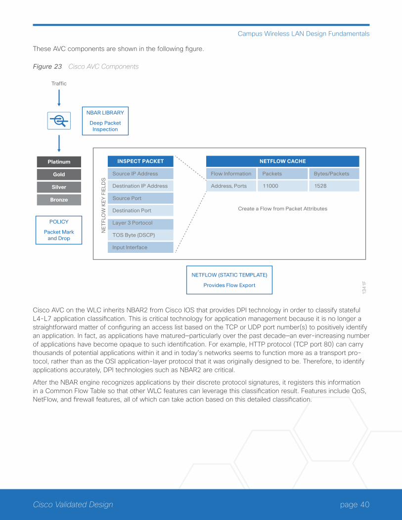
page 40Cisco Validated Design
Campus Wireless LAN Design Fundamentals
These AVC components are shown in the following figure.
Figure 23 Cisco AVC Components
NBAR LIBRARY
Deep PacketInspection
POLICY
Packet Markand Drop
NETFLOW (STATIC TEMPLATE)
Provides Flow Export
13
41
F
Platinum
Traffic
Gold
Silver
Bronze
INSPECT PACKET
Source IP Address
Destination IP Address
Source Port
Destination Port
Layer 3 Portocol
TOS Byte (DSCP)
Input Interface
NETFLOW CACHE
Flow Information
Address, Ports
Packets
11000
Bytes/Packets
1528
Create a Flow from Packet Attributes
NE
TFL
OW
KEY
FIE
LDS
Cisco AVC on the WLC inherits NBAR2 from Cisco IOS that provides DPI technology in order to classify stateful L4-L7 application classification. This is critical technology for application management because it is no longer a straightforward matter of configuring an access list based on the TCP or UDP port number(s) to positively identify an application. In fact, as applications have matured—particularly over the past decade—an ever-increasing number of applications have become opaque to such identification. For example, HTTP protocol (TCP port 80) can carry thousands of potential applications within it and in today’s networks seems to function more as a transport pro-tocol, rather than as the OSI application-layer protocol that it was originally designed to be. Therefore, to identify applications accurately, DPI technologies such as NBAR2 are critical.
After the NBAR engine recognizes applications by their discrete protocol signatures, it registers this information in a Common Flow Table so that other WLC features can leverage this classification result. Features include QoS, NetFlow, and firewall features, all of which can take action based on this detailed classification.
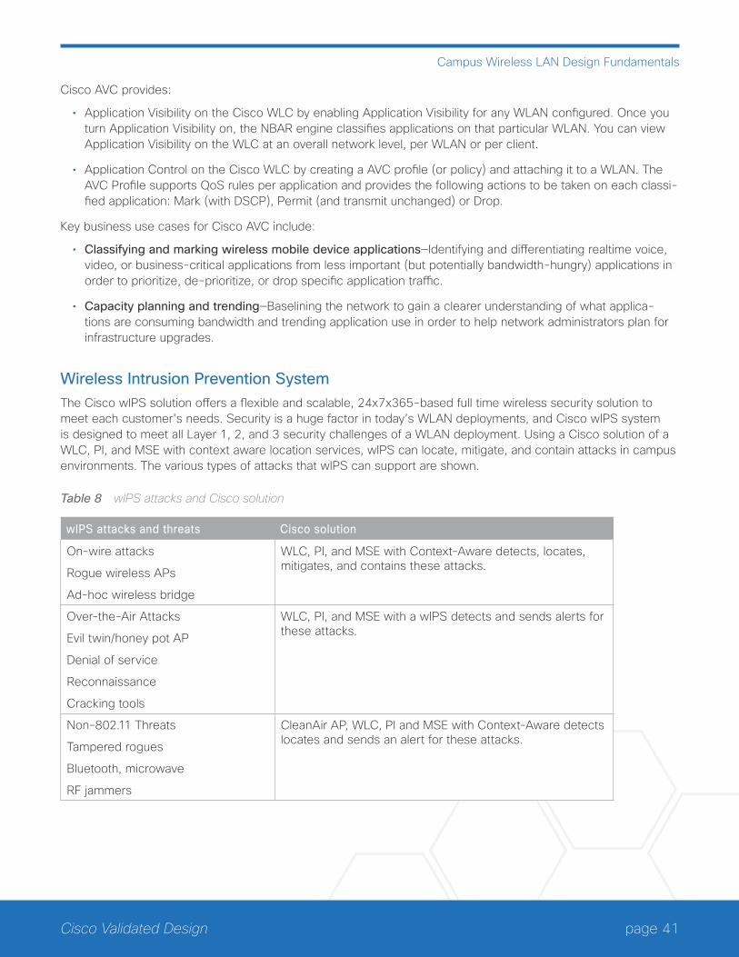
page 41Cisco Validated Design
Campus Wireless LAN Design Fundamentals
Cisco AVC provides:
• Application Visibility on the Cisco WLC by enabling Application Visibility for any WLAN configured. Once you turn Application Visibility on, the NBAR engine classifies applications on that particular WLAN. You can view Application Visibility on the WLC at an overall network level, per WLAN or per client.
• Application Control on the Cisco WLC by creating a AVC profile (or policy) and attaching it to a WLAN. The AVC Profile supports QoS rules per application and provides the following actions to be taken on each classi-fied application: Mark (with DSCP), Permit (and transmit unchanged) or Drop.
Key business use cases for Cisco AVC include:
• Classifying and marking wireless mobile device applications—Identifying and differentiating realtime voice, video, or business-critical applications from less important (but potentially bandwidth-hungry) applications in order to prioritize, de-prioritize, or drop specific application traffic.
• Capacity planning and trending—Baselining the network to gain a clearer understanding of what applica-tions are consuming bandwidth and trending application use in order to help network administrators plan for infrastructure upgrades.
Wireless Intrusion Prevention SystemThe Cisco wIPS solution offers a flexible and scalable, 24x7x365-based full time wireless security solution to meet each customer’s needs. Security is a huge factor in today’s WLAN deployments, and Cisco wIPS system is designed to meet all Layer 1, 2, and 3 security challenges of a WLAN deployment. Using a Cisco solution of a WLC, PI, and MSE with context aware location services, wIPS can locate, mitigate, and contain attacks in campus environments. The various types of attacks that wIPS can support are shown.
Table 8 wIPS attacks and Cisco solution
wIPS attacks and threats Cisco solution
On-wire attacks
Rogue wireless APs
Ad-hoc wireless bridge
WLC, PI, and MSE with Context-Aware detects, locates, mitigates, and contains these attacks.
Over-the-Air Attacks
Evil twin/honey pot AP
Denial of service
Reconnaissance
Cracking tools
WLC, PI, and MSE with a wIPS detects and sends alerts for these attacks.
Non-802.11 Threats
Tampered rogues
Bluetooth, microwave
RF jammers
CleanAir AP, WLC, PI and MSE with Context-Aware detects locates and sends an alert for these attacks.
page 42Cisco Validated Design
Campus Wireless LAN Design Fundamentals
On-wire Attacks
An AP in wIPS-optimized mode will perform rogue threat assessment and mitigation by using the same logic as current Cisco Unified Wireless Network implementations. This allows a wIPS AP to scan, detect, and contain rogue APs and ad hoc networks. Once discovered, this information regarding rogue wireless devices is reported to Cisco PI, where rogue alarm aggregation takes place. However, with this functionality comes the caveat that if a containment attack is launched using a wIPS mode AP, its ability to perform methodical attack-focused channel scanning is interrupted for the duration of the containment.
Over-the-Air Attacks
Cisco Adaptive wireless IPS embeds complete wireless threat detection and mitigation into the wireless network infrastructure to deliver the industry’s most comprehensive, accurate, and operationally cost-effective wireless security solution.
Non-802.11 Threats
Cisco CleanAir technology detects non-802.11 threats. CleanAir technology is an effective tool to monitor and manage your network’s RF conditions. Cisco MSE extends those capabilities.
Cisco Adaptive wIPS systemThe basic system components for a Cisco Adaptive wIPS system include:
• APs in Cisco wIPS monitor mode, in enhanced local mode, or with Cisco WSM
• WLAN controller(s)
• Cisco MSE running the Cisco wIPS service
• Cisco Prime Infrastructure
An integrated wIPS deployment is a system design in which non-wIPS mode APs and wIPS mode APs are in-termixed on the same controller(s) and managed by the same Prime Infrastructure. This can be any combination of local mode, FlexConnect mode, enhanced local mode, monitor mode, and 3600 or 3700 Series APs with the WSM. By overlaying wIPS protection and data shares using WSM on the APs, you can reduce infrastructure costs.
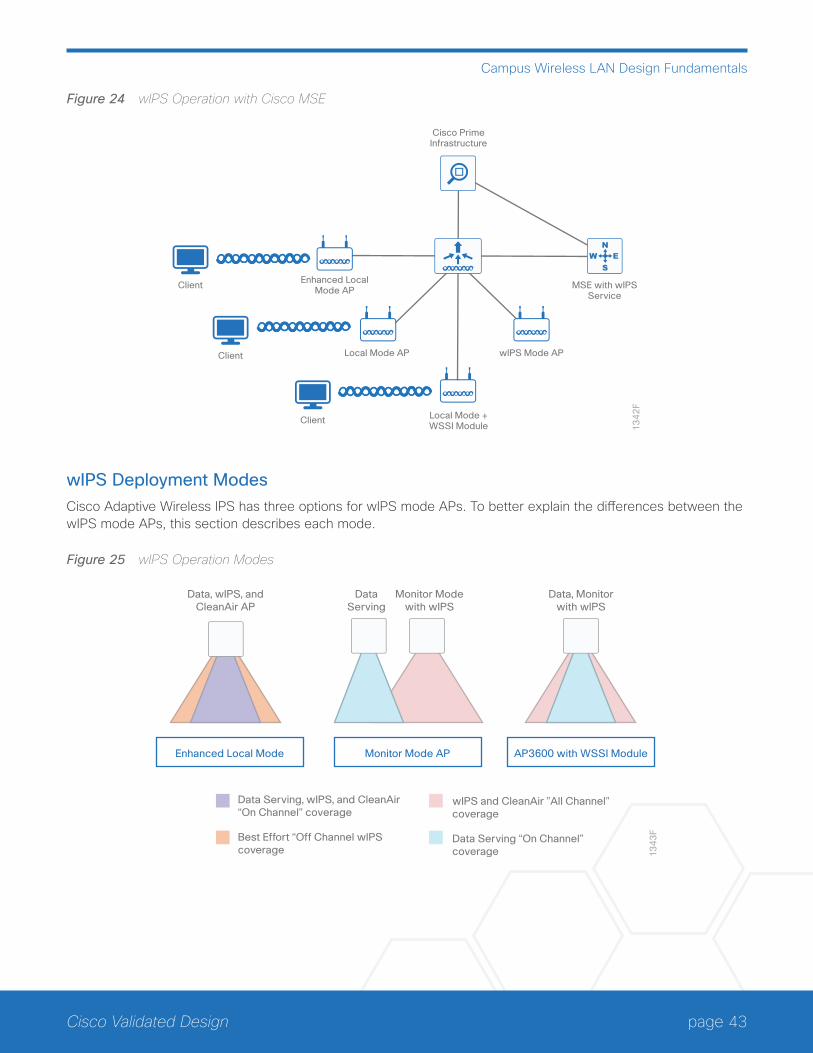
page 43Cisco Validated Design
Campus Wireless LAN Design Fundamentals
Figure 24 wIPS Operation with Cisco MSE
13
42
F
Cisco PrimeInfrastructure
Client Enhanced LocalMode AP
Local Mode AP
Local Mode +WSSI Module
MSE with wIPSService
wIPS Mode APClient
Client
wIPS Deployment ModesCisco Adaptive Wireless IPS has three options for wIPS mode APs. To better explain the differences between the wIPS mode APs, this section describes each mode.
Figure 25 wIPS Operation Modes
Monitor Mode APEnhanced Local Mode AP3600 with WSSI Module
13
43
F
Data, wIPS, andCleanAir AP
DataServing
Monitor Modewith wIPS
Data, Monitorwith wIPS
Data Serving, wIPS, and CleanAir“On Channel” coverage
Best Effort “Off Channel wIPS coverage
wIPS and CleanAir ”All Channel” coverage
Data Serving “On Channel” coverage
page 44Cisco Validated Design
Campus Wireless LAN Design Fundamentals
Enhanced Local Mode
ELM provides wIPS detection on-channel, which means attackers are detected on the channel that is serving cli-ents. For all other channels, ELM provides best-effort wIPS detection. This means that every frame the radio will go off-channel for a short period of time. While the radio is off-channel, if an attack occurs while that channel is scanned, te attack will be detected.
As an example of enhanced local mode on a 3700 Series AP, assume the 2.4 GHz radio is operating on channel 6. The AP will constantly monitor channel 6 and any attacks on channel 6 will be detected and reported. If an at-tack occurs on channel 11 while the AP is scanning channel 11 off-channel, the attack will be detected.
ELM features include:
• wIPS security scanning for 7x24 on- channel scanning (2.4 GHz and 5 GHz), with best effort off-channel support.
• AP additionally serving clients and with Cisco Aironet 2nd generation (G2) Series Access Points, CleanAir spectrum analysis is enabled on-channel (2.4 GHz and 5 GHz).
• Adaptive wIPS scanning in the data channel serving local and FlexConnect APs.
• Protection without requiring a separate overlay network.
• Support for PCI compliance for the WLANs.
• Full 802.11 and non-802.11 attack detection.
• Forensics and reporting capabilities.
• Flexibility to set integrated or dedicated Monitor Mode APs.
• Pre-processing at APs, which minimizes data backhaul (that is, works over very low bandwidth links).
• Low impact on the AP serving client data.
Monitor Mode
Monitor mode provides wIPS detection off-channel, which means the AP will dwell on each channel for an extend period of time, allowing the AP to detect attacks on all channels. The 2.4 GHz radio scans all 2.4 GHz channels, while the 5 GHz channel scans all 5 GHz channels. An additional AP would need to be installed for client access.
Some of the features of monitor mode:
• The monitor mode access point (MMAP) is dedicated to operate in monitor mode and can optionally add wIPS security scanning of all channels (2.4 GHz and 5 GHz).
• For Cisco Aironet G2 Series APs, CleanAir spectrum analysis is enabled on all channels (2.4 GHz and 5 GHz).
• MMAPs do not serve clients.
• A Cisco 3700 or 3600 Series AP with the WSM module uses a combination of on-channel and off-channel operation. This means that the AP 2.4 GHz and 5 GHz internal radios will scan the channel with which they are serving clients and the WSM module will additionally operate in monitor mode and scan all channels.
page 45Cisco Validated Design
Campus Wireless LAN Design Fundamentals
Rogue DetectionYou can regard as a rogue any device that shares your spectrum and that you are not managing. A rogue be-comes dangerous in the following scenarios:
• Rogue AP with the same SSID as your network (honeypot)
• Rogue AP device also on the wired network
• Ad-hoc rogues
• Rogues set up by an outsider with malicious intent
There are three main phases of rogue device management in the CUWN solution:
• Detection—The solution uses radio resource management (RRM scanning in order to detect the presence of rogue devices.
• Classification—The solution uses rogue location discovery protocol, rogue detectors, and switch port tracing in order to identify whether the rogue device is connected to the wired network. Rogue classification rules also assist in filtering rogues into specific categories based on their characteristics.
• Mitigation—The solution used switch port trace and shutting down, rogue location, and rogue containment in order to track down physical location and nullify the threat of rogue devices.
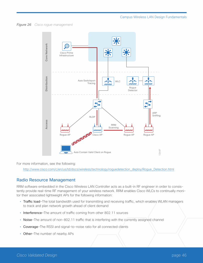
page 46Cisco Validated Design
Campus Wireless LAN Design Fundamentals
Figure 26 Cisco rogue management
13
44
F
Cisco PrimeInfrastructure
Rou
teL
ists
Rou
teG
rou
ps
Cor
e N
etw
ork
Dis
trib
uti
onA
cce
ss
WLC
RogueDetector
Rogue APRogue APCisco APRogue AP
Auto Contain Valid Client on Rogue
RRMScanning
ARPSniffing
Auto SwitchportTracing
RLDP
For more information, see the following:
http://www.cisco.com/c/en/us/td/docs/wireless/technology/roguedetection_deploy/Rogue_Detection.html
Radio Resource ManagementRRM software embedded in the Cisco Wireless LAN Controller acts as a built-in RF engineer in order to consis-tently provide real-time RF management of your wireless network. RRM enables Cisco WLCs to continually moni-tor their associated lightweight APs for the following information:
• Traffic load—The total bandwidth used for transmitting and receiving traffic, which enables WLAN managers to track and plan network growth ahead of client demand
• Interference—The amount of traffic coming from other 802.11 sources
• Noise—The amount of non-802.11 traffic that is interfering with the currently assigned channel
• Coverage—The RSSI and signal-to-noise ratio for all connected clients
• Other—The number of nearby APs
page 47Cisco Validated Design
Campus Wireless LAN Design Fundamentals
Using this information, RRM can periodically reconfigure the 802.11 RF network for best efficiency. To do this, RRM performs these functions:
• Radio resource monitoring
• Transmit power control
• Dynamic channel assignment
• Coverage hole detection and correction
RRM automatically detects and configures new Cisco WLCs and lightweight APs as they are added to the net-work. It then automatically adjusts associated and nearby lightweight APs to optimize coverage and capacity.
Lightweight APs can simultaneously scan all valid 802.11a/b/g/n/ac channels for the country of operation as well as for channels available in other locations. The APs go off-channel for a period not greater than 60 ms in order to monitor these channels for noise and interference. Packets collected during this time are analyzed in order to detect rogue APs, rogue clients, ad-hoc clients, and interfering APs
Tech Tip
In the presence of voice traffic (in the last 100 ms), the APs defer off-channel measurements.
Each AP spends only 0.2 percent of its time off-channel. This activity is distributed across all APs so that adjacent APs are not scanning at the same time, which could adversely affect WLAN performance.
Tech Tip
When there are numerous rogue APs in the network, the chance of detecting rogues on channels 157 or 161 by a FlexConnect or local mode AP is small. In such cases, you can use the monitor mode AP for rogue detection.
Transmit Power Control
The Cisco WLC dynamically controls AP transmit power based on real-time WLAN conditions. You can choose between two versions of transmit power control: TPCv1 and TPCv2. With TPCv1, typically power can be kept low to gain extra capacity and reduce interference. With TPCv2, transmit power is dynamically adjusted with the goal of minimum interference. TPCv2 is suitable for dense networks. In this mode, there could be higher roaming delays and coverage hole incidents.
The transmit power control (TPC) algorithm both increases and decreases an AP’s power in response to changes in the RF environment. In most instances, TPC seeks to lower an AP’s power to reduce interference, but in the case of a sudden change in the RF coverage—for example, if an AP fails or becomes disabled—TPC can also increase power on surrounding APs. This feature is different from coverage hole detection, which is primarily concerned with clients. TPC provides enough RF power to achieve desired coverage levels while avoiding chan-nel interference between APs.
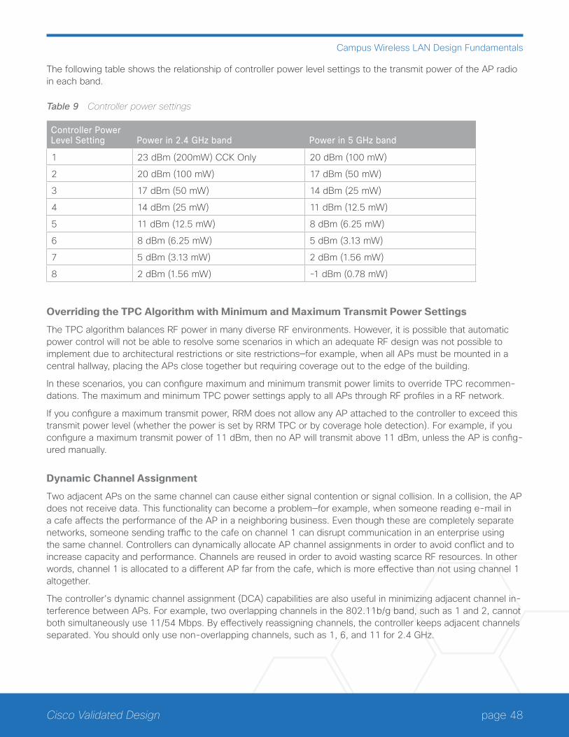
page 48Cisco Validated Design
Campus Wireless LAN Design Fundamentals
The following table shows the relationship of controller power level settings to the transmit power of the AP radio in each band.
Table 9 Controller power settings
Controller Power Level Setting Power in 2.4 GHz band Power in 5 GHz band
1 23 dBm (200mW) CCK Only 20 dBm (100 mW)
2 20 dBm (100 mW) 17 dBm (50 mW)
3 17 dBm (50 mW) 14 dBm (25 mW)
4 14 dBm (25 mW) 11 dBm (12.5 mW)
5 11 dBm (12.5 mW) 8 dBm (6.25 mW)
6 8 dBm (6.25 mW) 5 dBm (3.13 mW)
7 5 dBm (3.13 mW) 2 dBm (1.56 mW)
8 2 dBm (1.56 mW) -1 dBm (0.78 mW)
Overriding the TPC Algorithm with Minimum and Maximum Transmit Power Settings
The TPC algorithm balances RF power in many diverse RF environments. However, it is possible that automatic power control will not be able to resolve some scenarios in which an adequate RF design was not possible to implement due to architectural restrictions or site restrictions—for example, when all APs must be mounted in a central hallway, placing the APs close together but requiring coverage out to the edge of the building.
In these scenarios, you can configure maximum and minimum transmit power limits to override TPC recommen-dations. The maximum and minimum TPC power settings apply to all APs through RF profiles in a RF network.
If you configure a maximum transmit power, RRM does not allow any AP attached to the controller to exceed this transmit power level (whether the power is set by RRM TPC or by coverage hole detection). For example, if you configure a maximum transmit power of 11 dBm, then no AP will transmit above 11 dBm, unless the AP is config-ured manually.
Dynamic Channel Assignment
Two adjacent APs on the same channel can cause either signal contention or signal collision. In a collision, the AP does not receive data. This functionality can become a problem—for example, when someone reading e-mail in a cafe affects the performance of the AP in a neighboring business. Even though these are completely separate networks, someone sending traffic to the cafe on channel 1 can disrupt communication in an enterprise using the same channel. Controllers can dynamically allocate AP channel assignments in order to avoid conflict and to increase capacity and performance. Channels are reused in order to avoid wasting scarce RF resources. In other words, channel 1 is allocated to a different AP far from the cafe, which is more effective than not using channel 1 altogether.
The controller’s dynamic channel assignment (DCA) capabilities are also useful in minimizing adjacent channel in-terference between APs. For example, two overlapping channels in the 802.11b/g band, such as 1 and 2, cannot both simultaneously use 11/54 Mbps. By effectively reassigning channels, the controller keeps adjacent channels separated. You should only use non-overlapping channels, such as 1, 6, and 11 for 2.4 GHz.
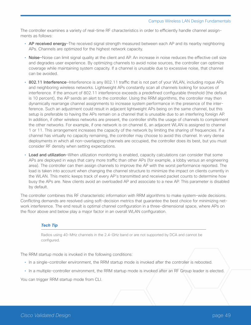
page 49Cisco Validated Design
Campus Wireless LAN Design Fundamentals
The controller examines a variety of real-time RF characteristics in order to efficiently handle channel assign-ments as follows:
• AP received energy—The received signal strength measured between each AP and its nearby neighboring APs. Channels are optimized for the highest network capacity.
• Noise—Noise can limit signal quality at the client and AP. An increase in noise reduces the effective cell size and degrades user experience. By optimizing channels to avoid noise sources, the controller can optimize coverage while maintaining system capacity. If a channel is unusable due to excessive noise, that channel can be avoided.
• 802.11 Interference—Interference is any 802.11 traffic that is not part of your WLAN, including rogue APs and neighboring wireless networks. Lightweight APs constantly scan all channels looking for sources of interference. If the amount of 802.11 interference exceeds a predefined configurable threshold (the default is 10 percent), the AP sends an alert to the controller. Using the RRM algorithms, the controller may then dynamically rearrange channel assignments to increase system performance in the presence of the inter-ference. Such an adjustment could result in adjacent lightweight APs being on the same channel, but this setup is preferable to having the APs remain on a channel that is unusable due to an interfering foreign AP. In addition, if other wireless networks are present, the controller shifts the usage of channels to complement the other networks. For example, if one network is on channel 6, an adjacent WLAN is assigned to channel 1 or 11. This arrangement increases the capacity of the network by limiting the sharing of frequencies. If a channel has virtually no capacity remaining, the controller may choose to avoid this channel. In very dense deployments in which all non-overlapping channels are occupied, the controller does its best, but you must consider RF density when setting expectations.
• Load and utilization—When utilization monitoring is enabled, capacity calculations can consider that some APs are deployed in ways that carry more traffic than other APs (for example, a lobby versus an engineering area). The controller can then assign channels to improve the AP with the worst performance reported. The load is taken into account when changing the channel structure to minimize the impact on clients currently in the WLAN. This metric keeps track of every AP’s transmitted and received packet counts to determine how busy the APs are. New clients avoid an overloaded AP and associate to a new AP. This parameter is disabled by default.
The controller combines this RF characteristic information with RRM algorithms to make system-wide decisions. Conflicting demands are resolved using soft-decision metrics that guarantee the best choice for minimizing net-work interference. The end result is optimal channel configuration in a three-dimensional space, where APs on the floor above and below play a major factor in an overall WLAN configuration.
Tech Tip
Radios using 40-MHz channels in the 2.4-GHz band or are not supported by DCA and cannot be configured.
The RRM startup mode is invoked in the following conditions:
• In a single-controller environment, the RRM startup mode is invoked after the controller is rebooted.
• In a multiple-controller environment, the RRM startup mode is invoked after an RF Group leader is elected.
You can trigger RRM startup mode from CLI.
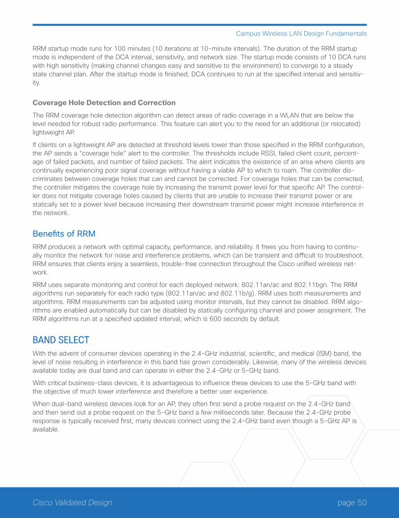
page 50Cisco Validated Design
Campus Wireless LAN Design Fundamentals
RRM startup mode runs for 100 minutes (10 iterations at 10-minute intervals). The duration of the RRM startup mode is independent of the DCA interval, sensitivity, and network size. The startup mode consists of 10 DCA runs with high sensitivity (making channel changes easy and sensitive to the environment) to converge to a steady state channel plan. After the startup mode is finished, DCA continues to run at the specified interval and sensitiv-ity.
Coverage Hole Detection and Correction
The RRM coverage hole detection algorithm can detect areas of radio coverage in a WLAN that are below the level needed for robust radio performance. This feature can alert you to the need for an additional (or relocated) lightweight AP.
If clients on a lightweight AP are detected at threshold levels lower than those specified in the RRM configuration, the AP sends a “coverage hole” alert to the controller. The thresholds include RSSI, failed client count, percent-age of failed packets, and number of failed packets. The alert indicates the existence of an area where clients are continually experiencing poor signal coverage without having a viable AP to which to roam. The controller dis-criminates between coverage holes that can and cannot be corrected. For coverage holes that can be corrected, the controller mitigates the coverage hole by increasing the transmit power level for that specific AP. The control-ler does not mitigate coverage holes caused by clients that are unable to increase their transmit power or are statically set to a power level because increasing their downstream transmit power might increase interference in the network.
Benefits of RRMRRM produces a network with optimal capacity, performance, and reliability. It frees you from having to continu-ally monitor the network for noise and interference problems, which can be transient and difficult to troubleshoot. RRM ensures that clients enjoy a seamless, trouble-free connection throughout the Cisco unified wireless net-work.
RRM uses separate monitoring and control for each deployed network: 802.11an/ac and 802.11bgn. The RRM algorithms run separately for each radio type (802.11an/ac and 802.11b/g). RRM uses both measurements and algorithms. RRM measurements can be adjusted using monitor intervals, but they cannot be disabled. RRM algo-rithms are enabled automatically but can be disabled by statically configuring channel and power assignment. The RRM algorithms run at a specified updated interval, which is 600 seconds by default.
BAND SELECTWith the advent of consumer devices operating in the 2.4-GHz industrial, scientific, and medical (ISM) band, the level of noise resulting in interference in this band has grown considerably. Likewise, many of the wireless devices available today are dual band and can operate in either the 2.4-GHz or 5-GHz band.
With critical business-class devices, it is advantageous to influence these devices to use the 5-GHz band with the objective of much lower interference and therefore a better user experience.
When dual-band wireless devices look for an AP, they often first send a probe request on the 2.4-GHz band and then send out a probe request on the 5-GHz band a few milliseconds later. Because the 2.4-GHz probe response is typically received first, many devices connect using the 2.4-GHz band even though a 5-GHz AP is available.
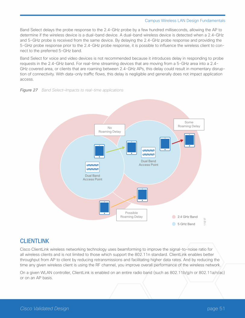
page 51Cisco Validated Design
Campus Wireless LAN Design Fundamentals
Band Select delays the probe response to the 2.4-GHz probe by a few hundred milliseconds, allowing the AP to determine if the wireless device is a dual-band device. A dual-band wireless device is detected when a 2.4-GHz and 5-GHz probe is received from the same device. By delaying the 2.4-GHz probe response and providing the 5-GHz probe response prior to the 2.4-GHz probe response, it is possible to influence the wireless client to con-nect to the preferred 5-GHz band.
Band Select for voice and video devices is not recommended because it introduces delay in responding to probe requests in the 2.4-GHz band. For real-time streaming devices that are moving from a 5-GHz area into a 2.4-GHz covered area, or clients that are roaming between 2.4-GHz APs, this delay could result in momentary disrup-tion of connectivity. With data-only traffic flows, this delay is negligible and generally does not impact application access.
Figure 27 Band Select—Impacts to real-time applications
Dual BandAccess Point
Dual BandAccess Point
2.4 GHz Band
5 GHz Band 11
81
F
Possible Roaming Delay
Some Roaming DelayNo
Roaming Delay
CLIENTLINKCisco ClientLink wireless networking technology uses beamforming to improve the signal-to-noise ratio for all wireless clients and is not limited to those which support the 802.11n standard. ClientLink enables better throughput from AP to client by reducing retransmissions and facilitating higher data rates. And by reducing the time any given wireless client is using the RF channel, you improve overall performance of the wireless network.
On a given WLAN controller, ClientLink is enabled on an entire radio band (such as 802.11b/g/n or 802.11a/n/ac) or on an AP basis.
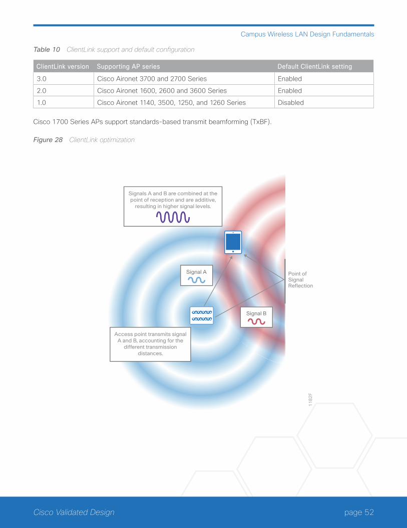
page 52Cisco Validated Design
Campus Wireless LAN Design Fundamentals
Table 10 ClientLink support and default configuration
ClientLink version Supporting AP series Default ClientLink setting
3.0 Cisco Aironet 3700 and 2700 Series Enabled
2.0 Cisco Aironet 1600, 2600 and 3600 Series Enabled
1.0 Cisco Aironet 1140, 3500, 1250, and 1260 Series Disabled
Cisco 1700 Series APs support standards-based transmit beamforming (TxBF).
Figure 28 ClientLink optimization
11
82
F
Point of Signal Reflection
Signal B
Signals A and B are combined at the point of reception and are additive,
resulting in higher signal levels.
Signal A
Access point transmits signal A and B, accounting for the
different transmission distances.
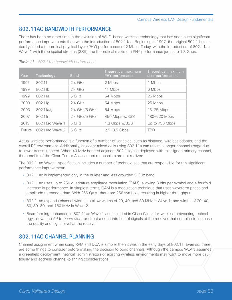
page 53Cisco Validated Design
Campus Wireless LAN Design Fundamentals
802.11AC BANDWIDTH PERFORMANCEThere has been no other time in the evolution of Wi-Fi–based wireless technology that has seen such significant performance improvements than with the introduction of 802.11ac. Beginning in 1997, the original 802.11 stan-dard yielded a theoretical physical layer (PHY) performance of 2 Mbps. Today, with the introduction of 802.11ac Wave 1 with three spatial streams (3SS), the theoretical maximum PHY performance jumps to 1.3 Gbps.
Table 11 802.11ac bandwidth performance
Year Technology BandTheoretical maximum PHY performance
Theoretical maximum user performance
1997 802.11 2.4 GHz 2 Mbps 1 Mbps
1999 802.11b 2.4 GHz 11 Mbps 6 Mbps
1999 802.11a 5 GHz 54 Mbps 25 Mbps
2003 802.11g 2.4 GHz 54 Mbps 25 Mbps
2003 802.11a/g 2.4 GHz/5 GHz 54 Mbps 13—25 Mbps
2007 802.11n 2.4 GHz/5 GHz 450 Mbps w/3SS 180—220 Mbps
2013 802.11ac Wave 1 5 GHz 1.3 Gbps w/3SS Up to 750 Mbps
Future 802.11ac Wave 2 5 GHz 2.5—3.5 Gbps TBD
Actual wireless performance is a function of a number of variables, such as distance, wireless adapter, and the overall RF environment. Additionally, adjacent mixed cells using 802.11a can result in longer channel usage due to lower transmit speed. When 40 MHz bonded adjacent 802.11a/n is deployed with misaligned primary channel, the benefits of the Clear Carrier Assessment mechanism are not realized.
The 802.11ac Wave 1 specification includes a number of technologies that are responsible for this significant performance improvement:
• 802.11ac is implemented only in the quieter and less crowded 5 GHz band.
• 802.11ac uses up to 256 quadrature amplitude modulation (QAM), allowing 8 bits per symbol and a fourfold increase in performance. In simplest terms, QAM is a modulation technique that uses waveform phase and amplitude to encode data. With 256 QAM, there are 256 symbols, resulting in higher throughput.
• 802.11ac expands channel widths, to allow widths of 20, 40, and 80 MHz in Wave 1; and widths of 20, 40, 80, 80+80, and 160 MHz in Wave 2.
• Beamforming, enhanced in 802.11ac Wave 1 and included in Cisco ClientLink wireless networking technol-ogy, allows the AP to beam steer or direct a concentration of signals at the receiver that combine to increase the quality and signal level at the receiver.
802.11AC CHANNEL PLANNINGChannel assignment when using RRM and DCA is simpler then it was in the early days of 802.11. Even so, there are some things to consider before making the decision to bond channels. Although the campus WLAN assumes a greenfield deployment, network administrators of existing wireless environments may want to move more cau-tiously and address channel-planning considerations.
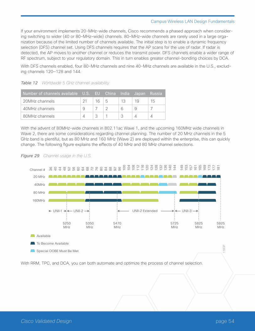
page 54Cisco Validated Design
Campus Wireless LAN Design Fundamentals
If your environment implements 20-MHz-wide channels, Cisco recommends a phased approach when consider-ing switching to wider (40 or 80-MHz-wide) channels. 80-MHz-wide channels are rarely used in a large orga-nization because of the limited number of channels available. The initial step is to enable a dynamic frequency selection (DFS) channel set. Using DFS channels requires that the AP scans for the use of radar. If radar is detected, the AP moves to another channel or reduces the transmit power. DFS channels enable a wider range of RF spectrum, subject to your regulatory domain. This in turn enables greater channel-bonding choices by DCA.
With DFS channels enabled, four 80-MHz channels and nine 40-MHz channels are available in the U.S., exclud-ing channels 120—128 and 144.
Table 12 Worldwide 5 GHz channel availability
Number of channels available U.S. EU China India Japan Russia
20MHz channels 21 16 5 13 19 15
40MHz channels 9 7 2 6 9 7
80MHz channels 4 3 1 3 4 4
With the advent of 80MHz-wide channels in 802.11ac Wave 1, and the upcoming 160MHz wide channels in Wave 2, there are some considerations regarding channel planning. The number of 20 MHz channels in the 5 GHz band is plentiful, but as 80 MHz and 160 MHz (Wave 2) are deployed within the enterprise, this can quickly change. The following figure explains the effects of 40 MHz and 80 MHz channel selections.
Figure 29 Channel usage in the U.S.
11
83
F
20 MHz
40MHz
80 MHz
160MHz
5250MHz
Available
To Become Available
Special OOBE Must Be Met
14
91
53
15
71
61
16
51
69
17
31
77
18
1
36
40
44
48
52
56
60
64
68
72
76
80
84
88
92
96
10
01
04
10
81
12
11
61
20
12
41
28
13
21
36
14
01
44
Channel #
5350MHz
5470MHz
5725MHz
5825MHz
5925MHz
UNII-1 UNII-2 UNII-2 Extended UNII-3
With RRM, TPC, and DCA, you can both automate and optimize the process of channel selection.
page 55Cisco Validated Design
Campus Wireless LAN Design Fundamentals
CAMPUS WIRELESS CLEANAIRCisco CleanAir is a spectrum intelligence solution designed to proactively manage the challenges of a shared wireless spectrum. It allows you to see all of the users of the shared spectrum (both native devices and foreign interferers). It also enables you or your network to act upon this information. For example, you could manually remove the interfering device or the system could automatically change the channel away from the interference. CleanAir provides spectrum management and RF visibility.
A Cisco CleanAir system consists of CleanAir-enabled APs, Cisco Wireless LAN Controllers, and Cisco Prime Infrastructure. These APs collect information about all devices that operate in ISM bands, identify and evaluate the information as a potential interference source, and forward it to the Cisco WLC. The Cisco WLC controls the APs, collects spectrum data, and forwards information to Cisco Prime Infrastructure or Cisco MSE upon request.
For every device operating in the unlicensed band, Cisco CleanAir tells you what it is, where it is, how it is impact-ing your wireless network, and what actions you or your network should take. It simplifies RF so that you do not have to be an RF expert.
WLAN systems operate in unlicensed 2.4- and 5-GHz ISM bands. Many devices, such as microwave ovens, cordless phones, and Bluetooth devices also operate in these bands and can negatively affect Wi-Fi operations.
Some of the most advanced WLAN services, such as voice over wireless and IEEE 802.11n radio communi-cations, could be significantly impaired by the interference caused by other legal users of the ISM bands. The integration of Cisco CleanAir functionality into the Cisco Unified Wireless Network addresses this problem of RF interference.
CleanAir is supported on mesh AP backhaul at a 5-GHz radio of mesh. You can enable CleanAir on backhaul radios and can provide report interference details and air quality.
Role of the Cisco WLC in a Cisco CleanAir DeploymentIn a Cisco CleanAir system, Cisco WLC:
• Configures Cisco CleanAir capabilities on the AP.
• Provides interfaces (GUI, CLI, and SNMP) for configuring Cisco CleanAir features and retrieving data.
• Displays spectrum data.
• Collects and processes air quality reports from the AP and stores them in the air quality database. The air quality report contains information about the total interference from all identified sources represented by the air quality index and summary for the most severe interference categories. The CleanAir system can also include unclassified interference information under per interference type reports, which enables you to take action in cases where the interference due to unclassified interfering devices is more.
• Collects and processes interference device reports from the AP and stores them in the interference device database.
• Forwards spectrum data to Cisco Prime Infrastructure and Cisco MSE.
page 56Cisco Validated Design
Campus Wireless LAN Design Fundamentals
Interference Types that Cisco CleanAir Can DetectCisco CleanAir can detect interference, report on the location and severity of the interference, and recommend different mitigation strategies. Two such mitigation strategies are persistent device avoidance and spectrum event-driven RRM.
Wi-Fi chip-based RF management systems share these characteristics:
• Any RF energy that cannot be identified as a Wi-Fi signal is reported as noise.
• Noise measurements that are used to assign a channel plan tend to be averaged over a period of time to avoid instability or rapid changes that can be disruptive to certain client devices.
• Averaging measurements reduces the resolution of the measurement. As such, a signal that disrupts clients might not look like it needs to be mitigated after averaging.
• All RF management systems available today are reactive in nature.
Cisco CleanAir is different and can positively identify not only the source of the noise but also its location and potential impact to a WLAN. Having this information allows you to consider the noise within the context of the network and make intelligent and, where possible, proactive decisions. For CleanAir, two types of interference events are common:
Persistent interference
Spontaneous interference
Persistent interference events are created by devices that are stationary in nature and have intermittent but largely repeatable patterns of interference. For example, consider the case of a microwave oven located in a break room. Such a device might be active for only 1 or 2 minutes at a time. When operating, however, it can be disruptive to the performance of the wireless network and associated clients. Using Cisco CleanAir, you can positively identify the device as a microwave oven rather than indiscriminate noise. You can also determine exactly which part of the band is affected by the device and because you can locate it, you can understand which APs are most severely affected. You can then use this information to direct RRM in selecting a channel plan that avoids this source of interference for the APs within its range. Because this interference is not active for a large portion of the day, existing RF management applications might attempt to again change the channels of the affected APs. Persistent device avoidance is unique, however, in that it remains in effect as long as the source of interference is periodi-cally detected to refresh the persistent status. The Cisco CleanAir system knows that the microwave oven exists and includes it in all future planning. If you move either the microwave oven or the surrounding APs, the algorithm updates RRM automatically.
Tech Tip
Spectrum event-driven RRM can be triggered only by Cisco CleanAir-enabled APs in local mode.
Spontaneous interference is interference that appears suddenly on a network, perhaps jamming a channel or a range of channels completely. The Cisco CleanAir spectrum event-driven RRM feature allows you to set a thresh-old for air quality (AQ) that, if exceeded, triggers an immediate channel change for the affected AP. Most RF man-agement systems can avoid interference, but this information takes time to propagate through the system. Cisco CleanAir relies on AQ measurements in order to continuously evaluate the spectrum and can trigger a move
page 57Cisco Validated Design
Campus Wireless LAN Design Fundamentals
within 30 seconds. For example, if an AP detects interference from a video camera, it can recover by changing channels within 30 seconds of the camera becoming active. Cisco CleanAir also identifies and locates the source of interference so that more permanent mitigation of the device can be performed at a later time.
In the case of Bluetooth devices, Cisco CleanAir-enabled APs can detect and report interferences only if the devices are actively transmitting. Bluetooth devices have extensive power save modes. For example, interference can be detected when data or voice is being streamed between the connected devices.
Persistent DevicesSome interference devices such as outdoor bridges and microwave ovens only transmit when needed. These devices can cause significant interference to the local WLAN due to short duration and periodic operation re-main largely undetected by normal RF management metrics. With CleanAir the RRM DCA algorithm can detect, measure, register, and remember the impact and adjust the DCA algorithm. This minimizes the use of channels affected by the persistent devices in the channel plan local to the interference source. Cisco CleanAir detects and stores the persistent device information in the Cisco WLC and this information is used to mitigate interfering channels.
Persistent Devices Detection
CleanAir-capable Monitor Mode AP collects information about persistent devices on all configured channels and stores the information in the Cisco WLC. Local/Bridge mode AP detects interference devices on the serving channels only.
Persistent Devices Propagation
Persistent device information that is detected by local or monitor mode APs is propagated to the neighboring APs connected to the same Cisco WLC in order to provide better chance of handling and avoiding persistent devices. Persistent device detected by the CleanAir-enabled AP is propagated to neighboring non-CleanAir APs, thus enhancing channel selection quality.
DETECTING INTERFERERS BY AN ACCESS POINTWhen a CleanAir-enabled AP detects interference devices, detections of the same device from multiple sen-sors are merged together to create clusters. Each cluster is given a unique ID. Some devices conserve power by limiting the transmit time until actually needed, which results in the spectrum sensor to temporarily stop detecting the device. This device is then correctly marked as down. A down device is correctly removed from the spectrum database. In cases when all the interferer detections for a specific devices are reported, the cluster ID is kept alive for an extended period of time to prevent possible device detection bouncing. If the same device is detected again, it is merged with the original cluster ID and the device detection history is preserved.
For example, some Bluetooth headsets operate on battery power. These devices employ methods to reduce power consumption, such as turning off the transmitter when not actually needed. Such devices can appear to come and go from the classification. To manage these devices, CleanAir keeps the cluster IDs longer and they are remerged into a single record upon detection. This process smoothens the user records and accurately rep-resents the device history.

page 58Cisco Validated Design
Campus Wireless LAN Design Fundamentals
SECURE WLANSWireless devices should connect to the network infrastructure securely where possible. In an enterprise environ-ment, you should configure WLANs to support WPA2 with AES-CCMP encryption, and 802.1x authentication of devices. This is sometimes referred to as WPA Enterprise on wireless devices. Most modern wireless devices support WPA2. The use of older security methods, such as WEP or WPA, is not recommended due to known security vulnerabilities. 802.1x authentication requires an AAA server—such as Cisco ISE or Cisco Access Control Server (ACS)—which provides centralized policy-based management and control for end-users accessing the wireless network.
Typically the AAA server will implement the RADIUS protocol between itself and the WLC. Authentication of end-users is accomplished via an extensible authentication protocol (EAP) session between the wireless device and the AAA server. The EAP session is transported via RADIUS between the WLC and the AAA server. Depending upon the capabilities of wireless device, the capabilities of the AAA server, and the security requirements of the organization, multiple variants of EAP, such as PEAP and EAP-TLS, may be implemented. PEAP makes use of standard user credentials (userid & password) for authentication. EAP-TLS makes use of digital certificates for authentication.
It is highly recommended that you deploy redundant AAA servers for high availability in case one or more servers become temporarily unavailable. Often the AAA server is configured to reference an external directory or data store such as Microsoft’s Active Directory (AD). This allows the network administrator to leverage existing AD credentials instead of duplicating them within the AAA server. This can also be extended to provide role-based access control (RBAC) for end-users through the use of AD groups. For example, it may be desirable to provide restricted network access to long-term contractors, as opposed to the access granted employees. The use of an external directory or data store can also provide a single point for granting or revoking credentials, not only for access to the network infrastructure, but for access to other resources within the organization. The AAA server itself can apply additional policy-based rules for authorization to the network, such device type, time of day, loca-tion, etc., depending upon the capabilities of the AAA server. AAA logs and accounting may be used to provide an audit trail of each employee’s access to the wireless network infrastructure.
The use of WPA2 with AES-CCMP encryption on the WLAN does not extend to management frames. Therefore the optional use of protected management frames (PMF) is advisable for WLANs where possible. PMF is part of the IEEE 802.11 standard, which provides a level of cryptographic protection to robust management frames such as de-authentication and dissociation frames, preventing them from being spoofed. It should be noted that the benefits of PMF does require wireless clients to support PMF. Cisco also offers an earlier version of Management Frame Protection (MFP) that has both infrastructure and client components.
In a home-office environment, it may be necessary to configure a WLAN to support WPA2 with pre-shared key (PSK). This is sometimes referred to as WPA Personal on wireless devices. This may be necessary because the implementation of an AAA server is not cost-effective for the number of end-users who access the WLAN. This may also be necessary in other environments if there is no end-user associated with a wireless device, the wire-less device does not support the ability to configure a userid & password, or the wireless device cannot support a digital certificate. Since the PSK is shared among all devices that access the wireless infrastructure, it may be necessary to change the PSK if an employee who knows the PSK leaves the organization. Furthermore, with WPA PSK, there is no easy audit trail of each employee’s access to the network.
The use of a dedicated, open WLAN is still common, but not ideal, for wireless guest access. Therefore the configuration of an unsecure WLAN on the network infrastructure may still be necessary. Open access guest WLANs are often implemented in order to minimize the complexity of onboarding a guest who needs only tempo-rary wireless network connectivity. Typically the guest WLAN is terminated outside the corporate firewall, which allows no access inbound to corporate resources, so guests may be allowed access to the Internet only.
page 59Cisco Validated Design
Campus Wireless LAN Design Fundamentals
Depending upon the requirements of the organization, guests may be required to authenticate before being al-lowed to access the Internet. Typically, a captive-portal model is used with WebAuth, in which guest web ses-sions are redirected to a portal which authenticates the guest before allowing Internet access.
Administrative Access ControlIt is recommended that you implement secure administrative access control to wireless infrastructure components in order to mitigate against unauthorized access. You can typically implement administrative access control via the local user database in each infrastructure device, or via a centralized AAA server—such as Cisco ISE or Cisco Secure ACS.
For a small number of network infrastructure devices, configuring individual local administrator accounts on each infrastructure device may be acceptable. It is recommended that the number of administrators be limited and that each administrator have a unique account. A shared administrator account limits the ability to audit who accessed a particular network device and potentially made configuration changes. When employees leave the organization, or move to other groups, their administrative access should be immediately revoked. With individual administrator accounts, only the account for the particular employee needs to be revoked.
As the number of infrastructure devices within the network grows, the administrative burden of configuring in-dividual local administrator accounts on each infrastructure device can become unmanageable. It is therefore recommended that you control administrative access via an AAA server, which provides centralized policy-based management and control. It is recommended that you deploy redundant AAA servers for high availability in case one or more servers becomes temporarily unavailable. Network administrators may still configure an individual local administrator account on each infrastructure device for local access via the console port, should all network access to the infrastructure device be lost.
The AAA server may itself reference an external directory or data store such as AD. This allows the network ad-ministrator to leverage existing AD credentials instead of duplicating them within the AAA server. This can also be extended to provide RBAC for administrators through the use of AD groups. The use of an external directory or data store can also provide a single point to grant or revoke credentials, not only for administrative access control to multiple infrastructure devices, but for access to other resources within the organization.
Where possible, the selection of a strong password—consisting of a minimum length, and combination of letters, numbers, and/or special characters—should be enforced. Where possible, a maximum number of unsuccess-ful attempts to access the device, before the account is disabled for a period of time, should also be enforced. Successful and unsuccessful attempts should be logged either locally or to a central logging server. This helps mitigate against (and/or alert appropriate network operations staff about) brute force attempts to gain access to infrastructure devices. Where multiple levels of administrative access are supported, it is recommended you enforce them, with administrators having the minimum access level required for performing their respective tasks. It is also recommended that you limit the number of concurrent logins from a single username.
It may be advantageous to limit where access to the wireless infrastructure device is initiated from and what protocols are allowed. You can accomplish this in multiple ways. For example, you can deploy the management interface of WLAN controllers on a separate VLAN (and therefore a separate IP subnet) from wireless client traf-fic. In such a deployment, an access-control list (ACL) deployed on the Layer 3 switch adjacent to the WLAN controller can limit access to the management interface. This shifts the CPU burden of an ACL off the WLAN controller to the Layer 3 switch. Alternatively, you can configure a CPU ACL on the WLAN controller to filter man-agement protocols. You can also disallow management of the WLAN controller via a wireless device, a method that may also provide additional security if the intention is to manage the wireless infrastructure from a central network operations center.
page 60Cisco Validated Design
Campus Wireless LAN Design Fundamentals
Access to wireless infrastructure devices should be via secure protocols such as HTTPS and SSHv2 where pos-sible. Access via non-encrypted protocols such as HTTP and Telnet should be disabled where possible. This protects the confidentiality of the information within the management session. When using SNMP, it is recom-mended that you enable SNMPv3 where possible. SNMPv2c relies on a shared community string that is sent in clear text across the network. Take caution when using SNMPv2c, particularly when using SNMP for read/write access. SNMPv3 uses unique credentials (userid/password) and can also provide encryption and data authenti-cation services to SNMP traffic.
Local ProfilingCisco ISE currently offers a rich set of features that provide device identification, onboarding, posture, and policy. As an alternative, local profiling on the WLC does the profiling of devices based on protocols such as HTTP and DHCP in order to identify the end devices on the network. The user can configure the device-based policies and enforce per user or per device policy on the network. The WLC will also display statistics based on per-user or per-device endpoints and policies applicable per device. With local profiling you can implement BYOD on a small scale within the WLC itself.
The profiling and policy enforcement are configured as two separate components. The configuration on the WLC is based on defined parameters specific to clients joining the network. The policy attributes which are of interest are:
• Role—Defines the user type or the user group to which the user belongs (Examples: Student or Employee)
• Device—Defines the type of device (Examples: Windows machine, smart phone, or Apple device)
• Time of day—Allows configuration to be defined at the time-of-day that endpoints are allowed on the network
• EAP Type—Checks the EAP method used by the client
The above parameters are configurable as policy match attributes. After the WLC has a match corresponding to the above parameters per end-point, the policy enforcement comes into picture. Policy enforcement will be based on session attributes such as:
• VLAN
• ACL
• Session timeout
• QoS
• Sleeping client
• Flexconnect ACL
• AVC profile (added in 8.0 release)
• mDNS profile (added in 8.0 release)
The user can configure these policies and enforce end-points with specified policies. The wireless clients are profiled based on the MAC OUI, DHCP, and HTTP user agent (valid Internet required for successful HTTP profil-ing). The WLC uses these attributes and predefined classification profiles to identify the device.
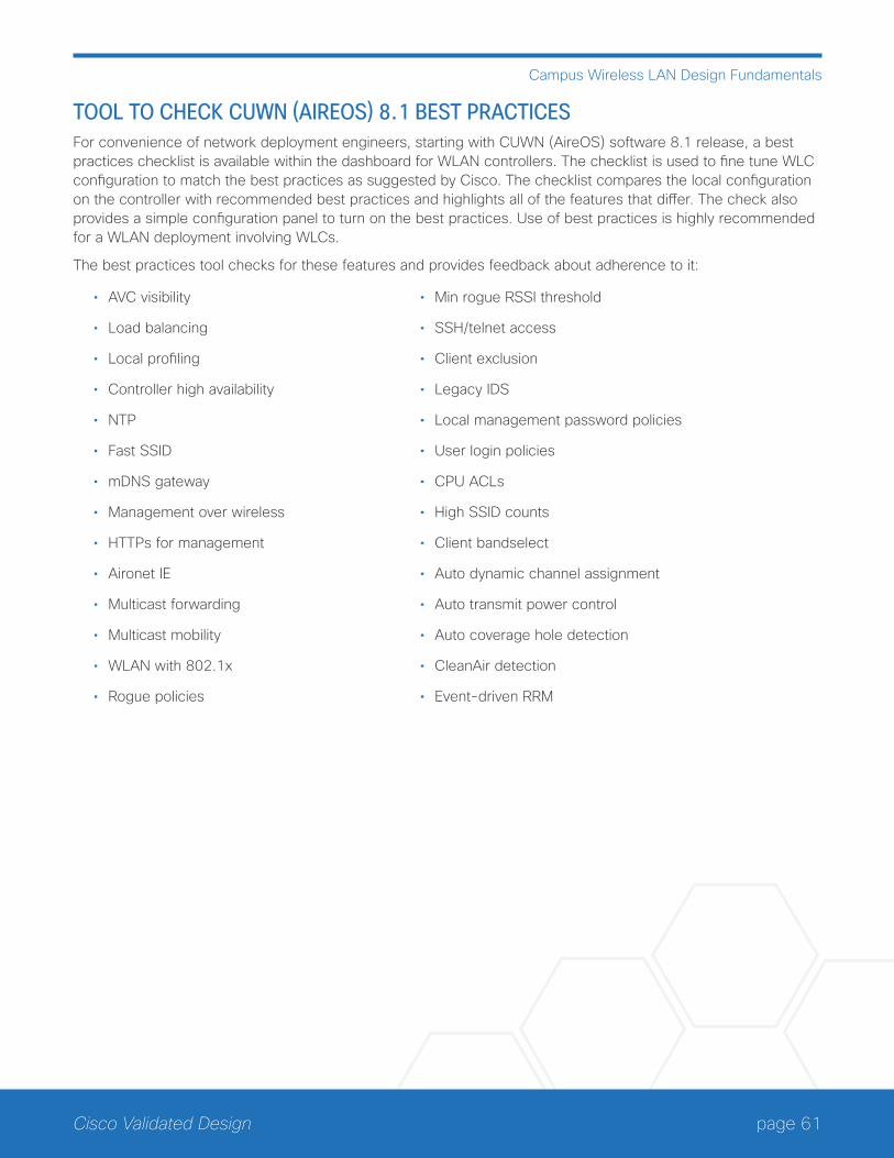
page 61Cisco Validated Design
Campus Wireless LAN Design Fundamentals
TOOL TO CHECK CUWN (AIREOS) 8.1 BEST PRACTICESFor convenience of network deployment engineers, starting with CUWN (AireOS) software 8.1 release, a best practices checklist is available within the dashboard for WLAN controllers. The checklist is used to fine tune WLC configuration to match the best practices as suggested by Cisco. The checklist compares the local configuration on the controller with recommended best practices and highlights all of the features that differ. The check also provides a simple configuration panel to turn on the best practices. Use of best practices is highly recommended for a WLAN deployment involving WLCs.
The best practices tool checks for these features and provides feedback about adherence to it:
• AVC visibility
• Load balancing
• Local profiling
• Controller high availability
• NTP
• Fast SSID
• mDNS gateway
• Management over wireless
• HTTPs for management
• Aironet IE
• Multicast forwarding
• Multicast mobility
• WLAN with 802.1x
• Rogue policies
• Min rogue RSSI threshold
• SSH/telnet access
• Client exclusion
• Legacy IDS
• Local management password policies
• User login policies
• CPU ACLs
• High SSID counts
• Client bandselect
• Auto dynamic channel assignment
• Auto transmit power control
• Auto coverage hole detection
• CleanAir detection
• Event-driven RRM
page 62Cisco Validated Design
Common Components in Campus Designs
Common Components in Campus Designs
DEVICE MANAGEMENT USING CISCO SECURE ACSWithout a centralized access and identity policy enforcement point, it’s difficult to ensure the reliability of a net-work as the number of network devices and administrators increases.
Cisco ACS operates as a centralized AAA server that combines user authentication, user and administrator ac-cess control, and policy control in a single solution. Cisco Secure ACS uses a rule-based policy model, which al-lows for security policies that grant access privileges based on many different attributes and conditions in addition to a user’s identity.
The capabilities of Cisco Secure ACS coupled with an AAA configuration on the network devices reduce the administrative issues that surround having static local account information on each device. Cisco Secure ACS can provide centralized control of authentication, which allows the organization to quickly grant or revoke access for a user on any network device.
Rule-based mapping of users to identity groups can be based on information available in an external directory or an identity store such as Microsoft Active Directory. Network devices can be categorized in multiple device groups, which can function as a hierarchy based on attributes such as location, manufacturer, or role in the net-work. The combination of identity and device groups allows you to easily create authorization rules that define which network administrators can authenticate against which devices.
These same authorization rules allow for privilege-level authorization, which can be used to give limited access to the commands on a device. For example, a rule can give network administrators full access to all commands or limit helpdesk users to monitoring commands.
CAMPUS DEPLOYMENT USING CISCO PRIME INFRASTRUCTUREAs networks and the number of services they support continue to evolve, the responsibilities of network adminis-trators to maintain and improve their efficiency and productivity also grow. Using a network management solution can enable and enhance the operational efficiency of network administrators.
Cisco Prime Infrastructure is a sophisticated network management tool that can help support the end-to-end management of network technologies and services that are critical to the operation of your organization; it aligns network management functionality with the way that network administrators do their jobs. Cisco Prime Infrastruc-ture provides an intuitive, web-based GUI that can be accessed from anywhere from within the network and gives you a full view of a network use and performance.
With a campus network and the services that it can support, Cisco Prime Infrastructure can play a critical role in day-to-day network operations.
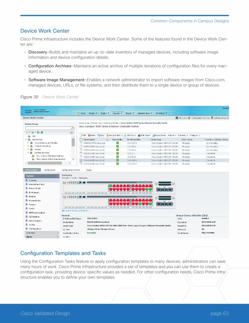
page 63Cisco Validated Design
Common Components in Campus Designs
Device Work CenterCisco Prime Infrastructure includes the Device Work Center. Some of the features found in the Device Work Cen-ter are:
• Discovery—Builds and maintains an up-to-date inventory of managed devices, including software image information and device configuration details.
• Configuration Archives—Maintains an active archive of multiple iterations of configuration files for every man-aged device.
• Software Image Management—Enables a network administrator to import software images from Cisco.com, managed devices, URLs, or file systems, and then distribute them to a single device or group of devices.
Figure 30 Device Work Center
Configuration Templates and TasksUsing the Configuration Tasks feature to apply configuration templates to many devices, administrators can save many hours of work. Cisco Prime Infrastructure provides a set of templates and you can use them to create a configuration task, providing device-specific values as needed. For other configuration needs, Cisco Prime Infra-structure enables you to define your own templates.
page 64Cisco Validated Design
Common Components in Campus Designs
Alarms, Events, and Syslog MessagesCisco Prime Infrastructure provides the Alarms and Events feature, which is a unified display with detailed foren-sics. The feature provides actionable information and the ability to automatically open service requests with the Cisco Technical Assistance Center.
ReportingCisco Prime Infrastructure provides you a single launch point for all reports that you can configure, schedule, and view. The Report Launch Pad page provides access to over 100 reports, each of which you can customize as needed.
CleanAir SupportCisco Prime Infrastructure supports the management of CleanAir enabled wireless APs, enabling administrators to see interference events.
Network Analysis Module SupportFor increased visibility into your network, Cisco Prime Infrastructure supports management and reporting for Cisco Network Analysis Module products.
MERAKI CLOUD MANAGEMENTMeraki’s cloud-based management provides centralized visibility & control over Meraki’s wired and wireless net-working hardware, without the cost and complexity of wireless controllers or overlay management systems.
CAMPUS QUALITY OF SERVICEBecause real-time communication traffic is very sensitive to delay and drop, the network must ensure that this type of traffic is handled with priority so that the stream of audio or video is not interrupted. QoS is the technology that answers this need.
The primary role of QoS in rich-media campus networks is to manage packet loss, where high-bandwidth links with instantaneous congestion on the order of milliseconds can cause buffer overruns and a poor user experi-ence. Another goal of campus QoS is to apply policies to at the edge to allow consistent treatment of traffic for a predictable user experience across the entire enterprise network.
QoS allows an organization to define different traffic types and to create more deterministic handling for real-time traffic. QoS is especially useful in congestion handling, where a full communications channel might prevent voice or video streams from being intelligible at the receiving side. Congestion is common when links are over-subscribed by aggregating traffic from a number of devices, and also when traffic on a link to a device has come from upstream links with greater bandwidth. Rather than creating bandwidth, QoS takes bandwidth from one class and gives it to another class.
Within the campus wired LAN, Cisco keeps the QoS profiles as simple as possible while ensuring support for applications that need special delivery. This approach establishes a solid, scalable, and modular framework to implement QoS across the entire network.
page 65Cisco Validated Design
Common Components in Campus Designs
The primary goals of implementing QoS within the network are:
• Expedited delivery service of communications for supported, real-time applications.
• Business continuance for business-critical applications.
• Fairness among all other applications when congestion occurs.
• Deprioritized background applications and non-business entertainment-oriented applications so that these do not delay interactive or business-critical applications.
• A trusted edge around the network to guarantee that users cannot inject their own arbitrary priority values and to allow the organization to trust marked traffic throughout the network.
To accomplish these goals, the design implements QoS across the network as follows:
• Establish a limited number of traffic classes (that is, one to eight classes) within the network that need special handling (for example, real-time voice, real-time video, high-priority data, interactive traffic, batch traffic, and default classes).
• Classify applications into the traffic classes.
• Apply special handling to the traffic classes to achieve intended network behavior.
page 66Cisco Validated Design
Appendix—Glossary
Appendix—Glossary3SS three spatial streams
AAA server authentication, authorization, and accounting server
ACL access control list
ACS Cisco Access Control Server
AP access point
AQ air quality
AUP acceptable use policy
AVC Cisco Application Visibility and Control
BYOD bring your own device
CAPWAP control and provisioning of wireless access points protocol
Cisco ACS Cisco Access Control Server
Cisco AVC Cisco Application Visibility and Control
Cisco CMX Cisco Connected Mobile Experiences
Cisco ISE Cisco Identity Services Engine
Cisco MSE Cisco Mobility Services Engine
Cisco PI Cisco Prime Infrastructure
Cisco UPOE Cisco Universal Power Over Ethernet
Cisco wIPS Cisco Wireless Intrusion Prevention System
CMX Cisco Connected Mobile Experiences
CUWN Cisco Unified Wireless Network
DCA dynamic channel assignment
DFS dynamic frequency selection
DMZ demilitarized zone
DPI deep packet inspection
EAP extensible authentication protocol
EUA end-user agreement
G2 second generation
GLBP gateway load-balancing protocol
HA high availability
HA SSO high availability stateful switchover
HSRP hot standby routing protocol
ISE Cisco Identity Services Engine

page 67Cisco Validated Design
Appendix—Glossary
ISM industrial, scientific, and medical band
LACP link aggregation protocol
LAG link aggregation
LAN local area network
mDNS multicast domain name services
MFP Management Frame Protection
MIMO multiple input, multiple output design
MMAP monitor mode access point
MSE Cisco Mobility Services Engine
NBAR2 Next Generation Network-Based Application Recognition
PAgP port aggregation protocol
PHY physical layer
PI Cisco Prime Infrastructure
PMF protected management frames
PSK pre-shared key
QAM quadrature amplitude modulation
QoS quality of service
RBAC role-based access control
RF radio frequency
RRM radio resource management
RSSI received signal strength
SSID service set identifier
SSO stateful switchover
STP spanning tree protocol
TPC transmit power control
TTL time-to-live
TxBF standards-based transmit beamforming
UPOE Cisco Universal Power Over Ethernet
VLAN virtual local area network
VRRP virtual router redundancy protocol
VSS virtual switching system
vWLC virtual wireless local area network controller
WAAS Wide Area Application Services
WAN wireless LAN
page 68Cisco Validated Design
Appendix—Glossary
WIDS wireless intrusion detection system
wIPS Cisco Wireless Intrusion Prevention System
WLAN wireless local area network
WLC wireless local area network controller
WSM Wireless Security Module
Americas HeadquartersCisco Systems, Inc.San Jose, CA
Asia Pacific HeadquartersCisco Systems (USA) Pte. Ltd.Singapore
Europe HeadquartersCisco Systems International BV Amsterdam,The Netherlands
Cisco has more than 200 offices worldwide. Addresses, phone numbers, and fax numbers are listed on the Cisco Website at www.cisco.com/go/offices.
ALL DESIGNS, SPECIFICATIONS, STATEMENTS, INFORMATION, AND RECOMMENDATIONS (COLLECTIVELY, “DESIGNS”) IN THIS MANUAL ARE PRESENTED “AS IS,” WITH ALL FAULTS. CISCO AND ITS SUPPLIERS DISCLAIM ALL WARRANTIES, INCLUDING, WITHOUT LIMITATION, THE WARRANTY OF MERCHANTABILITY, FITNESS FOR A PARTICULAR PURPOSE AND NONINFRINGEMENT OR ARISING FROM A COURSE OF DEALING, USAGE, OR TRADE PRACTICE. IN NO EVENT SHALL CISCO OR ITS SUPPLIERS BE LIABLE FOR ANY INDIRECT, SPECIAL, CONSEQUENTIAL, OR INCIDENTAL DAMAGES, INCLUDING, WITHOUT LIMITATION, LOST PROFITS OR LOSS OR DAMAGE TO DATA ARISING OUT OF THE USE OR INABILITY TO USE THE DESIGNS, EVEN IF CISCO OR ITS SUPPLIERS HAVE BEEN ADVISED OF THE POSSIBILITY OF SUCH DAMAGES. THE DESIGNS ARE SUBJECT TO CHANGE WITHOUT NOTICE. USERS ARE SOLELY RESPONSIBLE FOR THEIR APPLICATION OF THE DESIGNS. THE DESIGNS DO NOT CONSTITUTE THE TECHNICAL OR OTHER PROFESSIONAL ADVICE OF CISCO, ITS SUPPLIERS OR PARTNERS. USERS SHOULD CONSULT THEIR OWN TECHNICAL ADVISORS BEFORE IMPLEMENTING THE DESIGNS. RESULTS MAY VARY DEPENDING ON FACTORS NOT TESTED BY CISCO.
Any Internet Protocol (IP) addresses used in this document are not intended to be actual addresses. Any examples, command display output, and figures included in the document are shown for illustrative purposes only. Any use of actual IP addresses in illustrative content is unintentional and coincidental.
© 2015 Cisco Systems, Inc. All rights reserved.
Cisco and the Cisco logo are trademarks or registered trademarks of Cisco and/or its affiliates in the U.S. and other countries. To view a list of Cisco trademarks, go to this URL: www.cisco.com/go/trademarks. Third-party trademarks mentioned are the property of their respective owners. The use of the word partner does not imply a partnership relationship between Cisco and any other company. (1110R)
Cisco Validated Design
Please use the feedback form to send comments and suggestions about this guide.
B-000120c-2 10/15


