Campus Network Best Practices: Hints on Network Diagrams Dale Smith Network Startup Resource Center [email protected]This document is a result of work by the Network Startup Resource Center (NSRC at http:// www.nsrc.org ). This document may be freely copied, modified, and otherwise re-used on the condition that any re-use acknowledge the NSRC as the original source.
Transcript
Campus Network Best Practices:Hints on Network Diagrams
Dale Smith
Network Startup Resource Center
[email protected] document is a result of work by the Network Startup Resource Center (NSRC at http://www.nsrc.org). This document may be
freely copied, modified, and otherwise re-used on the condition that any re-use acknowledge the NSRC as the original source.
• Use separate diagrams for separate layers– Physical (cabling) – Switching (layer 2)– Routing (layer 3)– Frequently can combine Switching/Routing
• Helpful to have the physical diagram be an overlay on your campus map to show relations and distances between buildings
• If you combine layer 2/3, make it clear where you are switching and where you are routing
Sample Physical Diagram
8x62.5 fiber2x62.5 fiber
12xG.652.D fiber
2xcat5e
2.4Ghz 54Mbswireless
4xG.652.D fiber 4xG.652.D fiber
Splice
Sample Layer 3 Diagram
ISP
Cisco 3750-12DCore Router
Cisco 2901Border Router (no NAT)
128.223.2.64/29
128.223.10.0/24
128.223.12.0/23
128.223.14.0/24
128.223.20.0/24
128.223.16.0/24Server Network
Admin Building Social Science Faculty
General Science Faculty
Art Faculty
62.63.64.32/29
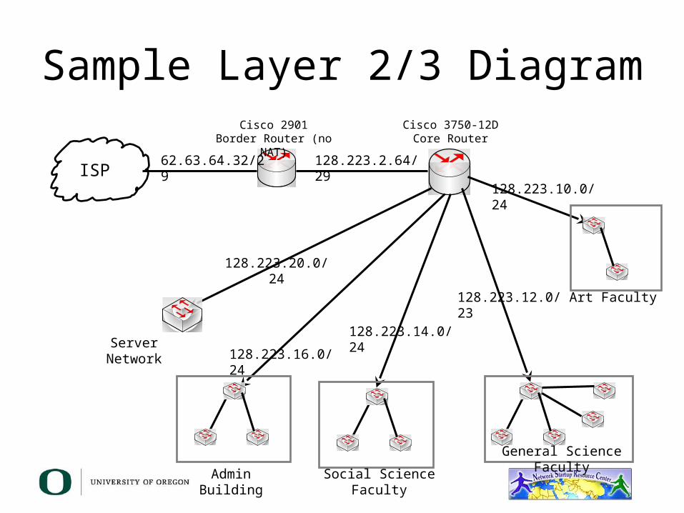
Sample Layer 2/3 Diagram
ISP
Cisco 3750-12DCore Router
128.223.2.64/29
128.223.10.0/24
128.223.12.0/23
128.223.14.0/24
128.223.20.0/24
128.223.16.0/24
Art Faculty
General Science Faculty
Social Science FacultyAdmin Building
Server Network
62.63.64.32/29
Cisco 2901Border Router (no NAT)
Questions?
This document is a result of work by the Network Startup Resource Center (NSRC at http://www.nsrc.org). This document may be freely copied, modified, and otherwise re-used on the condition that any re-use acknowledge the NSRC as the original source.