AbstractSheep model is the most favourable choice for animal study for functional evaluation of the cervical fusion prostheses beforeclinical application; however, significantly large differences between sheep and human existed in terms of morphologicalcharacteristics and daily-activity motions. Questions should be raised as whether the differences between the two specieshave influence on the reliability of sheep model. Finite element models (FEM) of the cervical spinal system were built tocharacterize the differences between the two species with respect to the range of motion (ROM) and biomechanical behaviour,and experimental cadaver tests on both species were employed for validation purposes. Results indicate that sheep modelrepresents the worst-case scenario of the human model with exaggerated stresses (up to 3 times more) and ROM (up to 10times more). Moreover, sheep model is very sensitive to the variation of prostheses design, whilst human model does not,which denotes that the sheep model provides a rather amplified effect of a certain design for its biomechanical performance.Therefore, caution needs to be taken when sheep models were used as the animal model for functional evaluation over variousdesign, and the FEM built in this study can be employed as an effective methodology for performance evaluation of cageprostheses of cervical spine.
Keywords Cervical interbody fusion cage · Spinal disc · Biomechanics · Range of motion · Animal study
1 Introduction
Artificial interbody fusion cage prostheses have been widelyused for the functional reconstruction of cervical spines. Ani-mal tests are normally the routine and critical pre-clinicaltests carried out for new materials or designs of cervicalfusion prostheses. Owing to the similarities in anatomicstructure, lordosis, material properties, and biomechanicsbetween the sheep cervical spine (SCS) and the human cer-vical spine (HCS) (Wilke et al. 1997), the SCS was usually
1 School of Mechanical Engineering, Xi’an JiaotongUniversity, Xi’an 710054, Shaanxi, China
2 State Key Laboratory for Manufacturing System Engineering,School of Mechanical Engineering, Xi’an JiaotongUniversity, Xi’an 710054, Shaanxi, China
3 Department of Orthopedics, Xijing Hospital, The FourthMilitary Medical University, Xi’an, China
4 Department of Orthopedics, Honghui Hospital, Xi’an, China
chosen for in vivo and in vitro experiments (Daentzer et al.2015; Kandziora et al. 2001a; Li et al. 2015; Yamada et al.2015). However, differences between these species do existin the geometric morphology and dimension of vertebrae,e.g. sheep cervical vertebrae do not have uncovertebral jointslike human ones do, and the superior endplate of a sheep’scervical vertebral body is convex, whereas that of a human’scervical vertebral body is concave (Fig. 1a). In addition, theheight of a sheep cervical vertebral body is almost three timesthat of a human, and the disc space is larger in the SCS thanin the HCS; details of these differences are summarized inFig. 1b (Kandziora et al. 2001b). Therefore, questions havebeen raised as whether the differences between the SCS andthe HCS influence the reliability of employing the sheep asthe animal model for the HCS in pre-clinical tests.
In the literature, animal tests have normally been eval-uated via imaging, histology, and biomechanical analyses(Hong et al. 2014; Li et al. 2015; Yamada et al. 2015). µCTscanning images have been used to evaluate the fusion levels,histological tests have been carried out to determine bone in-growth levels, and biomechanics analyses have been carried
Fig. 1 Summarized differences between the sheep cervical spine andthe human cervical spine: a anatomic structure; b anatomic parame-ters. VBHa: anterior vertebral body height, VBHp: posterior vertebral
body height, EPDu: upper endplate depth, EPDl: lower endplate depth,EPWu: upper endplate width, EPWl: lower endplate width, DSHm:mean disc space height (Kandziora et al. 2001b)
out to evaluate the range of motion (ROM) and stability ofthe systems. The evaluation results from such imaging andhistology analyseswere highly affected by the characteristicsof the biomechanics of the systems. The differences betweenthe geometrical characteristics of the spinal vertebrae of thesheep and human species may result in differences in thebiomechanics of the system, which would consequently leadto differences between the evaluation results obtained fromthe imaging and histological methodologies.
There are very little quantitative data in the literature onthe biomechanics of the SCS fusion in comparison with thatfor HCS fusion. However, it is important to understand howwell a sheep model can represent a humanmodel for cervicalfusion surgeries in terms of the biomechanics and kinetics ofthe cervical spine in order to evaluate the performance of theprostheses for the pre-clinical tests in a more accurate man-ner. Therefore, the aim of this study was to investigate thedifferences between the human and sheep cervical modelfrom the viewpoint of cervical fusion surgery when per-forming daily activities, by employing finite element method(FEM) and mechanical tests. This study may offer someimportant insights into performing functional evaluations ofthe interbody fusion cage using animal models.
2 Materials andmethods
In this study, finite element models of cervical spine for bothhuman and sheep are constructed from µCT scanning data(ethics committee of the Fourth Military University Hospitalof China). Based on the constructed model, biomechanics ofthe spinal discs were studied for both species in the intactmanner. Then, the models with the designed PEEK inter-
body fusion cage in situ were constructed for both species tostudy the biomechanics between the discs and the surround-ing tissue when undergoing various physiological loadingenvironments.
2.1 Finite elementmodel construction
Three-dimensional, nonlinear FE models of the humanC4–C5 motion segment and the sheep C3–C4 motion seg-ment were built separately from a µCT image dataset ofcadaveric specimens (4months old, 50 kg). The sheepC3–C4motion segment was chosen in particular because it is themost reliablemodel for the correspondinghumanmotion seg-ment (Kandziora et al. 2001b), and the humanC4–C5motionsegment (56-year-old female, 50 kg) was chosen because itis similar to other segments in the HCS model (Panzer andMatthew 2006). A three-dimensional model was constructedfrom the stack of CT images using MIMICS 16.0 (Mate-rialise, Leuven, Belgium) and was subsequently smoothedin Geomagic Studio 12.0 (Geomagic, Inc, Research Trian-gle Park, NC, USA) for removing the uneven surfaces, sharpcorners, etc. A model of the intervertebral disc between thetwo adjacent vertebrae was created inGeomagic based on thespace between the two adjacent bottom endplates of the twovertebrae models by employing a cylindrical geometry, fromwhich the annulus ground and nucleus were partitioned.
The models of the vertebrae and intervertebral disc weremeshed using HyperMesh v12.0 (Altair, California, USA).A vertebra model consists of a vertebral body and a poste-rior part, and the vertebral body is composed of a cancellouscore and a cortical shell with a thickness of 0.5 mm (Ha2006). The cortical bone of the vertebral body was meshedusing the six-node triangular prism element (C3D6), and the
123
Can the sheep model fully represent the human model for the functional evaluation of…
Table 1 Material properties ofthe different components used inthe finite element models of thesheep cervical spine (SCS) andthe human cervical spine (HCS)(Faizan et al. 2012)
cancellous bone was meshed using the four-node tetrahedralelement (C3D4). Both endplates of the vertebral body wereconsidered to be cortical bone. The intervertebral discs werealsomeshed using theC3D4 element. Five primary ligaments(anterior longitudinal ligament (ALL), posterior longitudinalligament (PLL), flaval ligament (FL), facet capsular ligament(CL), and interspinous ligament (ISL)) were modelled usingthree-dimensional truss elements (T3D2) corresponding tothe tensile stresses only (Faizan et al. 2012). The materialproperties of each component of the model were taken fromthe literature (DeVries 2011; Galbusera et al. 2006; Kalle-meyn et al. 2010; Natarajan et al. 2000; Zhang et al. 2006),as shown in Table 1. The facet cartilage joints were modelledas contacts with a coefficient of friction of 0.1 and an initialgap of 0.5 mm in the HCSmodel, whereas the ‘softened con-tact’ of an exponential pressure–overclosure relation with an
initial gap of 0.5 mm was set for the facet cartilage joints ofthe SCS model (Faizan et al. 2012).
For the intact HCS model, the inferior surface of the C5vertebral body was fully constrained, and a vertical load of50 N was applied axially on the superior surface of the C4vertebral body to simulate the weight of the head. A flex-ion–extension (FLX–EXT) moment of 1.0 Nm, a left–rightlateral bending (LLB–RLB) moment of 1.0 Nm, and a left-–right axial rotational (LAR–RAR) moment of 1.0 Nm wereimposed individually on to the C4 body to carry out multi-activity simulations. For the intact SCS model, the inferiorsurface of the C4 vertebral body was fully constrained, andmoments of 2.5 Nm for various bending motions and rota-tional orientations were imposed to the superior surface ofthe C3 vertebral body (Wilke et al. 1997). FE analyses wereperformed using Abaqus 6.14 (SIMULIA, Providence, RI,USA).
123
L. Wang et al.
Fig. 2 FEmodel set-up of sheep cervical spine (C3–C4, left) and humancervical spine (C4–C5, right) after interbody fusion cage insertion(FBC: flat box-shaped cage, CBC: curved box-shaped cage)
Mesh convergence was carried out on both the HCS andthe SCS models for verification purposes. The results indi-cated that a global element size of 1 mm (104,596 elementsfor HCS, and 269,858 elements for SCS) was good enoughfor both theHCS and SCSmodels to keep the numerical errorof von Mises stress below 5%. The intact models of the HCSand the SCSwere validated viamechanical tests on cadavericsamples.
2.2 FEmodel with interbody fusion cage
Based on the aforementioned intact HCS and SCS mod-els, the primary postoperative ACDF model was created byremoving the original intervertebral disc and replacing it withthe designed interbody fusion cage embeddedwith graft boneto simulate the surgical procedure (Natarajan et al. 2000). Inthis study, two types of the most popular interbody fusioncages were studied: the flat box-shaped cage (FBC) and thecurved box-shaped cage (CBC), as shown in Fig. 2.
The material properties of the cage were set to be those ofpolyetheretherketone (PEEK) in order to be consistent witha previous mechanical test (Vadapalli et al. 2006), whichused a PEEK cage manufactured via 3D printing technol-ogy (Fig. 3f/g). The material properties of the graft wereset to be those of the tricortical iliac crest bone graft. Thematerial properties for all components were assumed to belinear elastic and isotropic, as shown in Table 1. Addition-ally, the contact surfaces between the vertebra body and thecage with graft bone were assumed to be fully integrated into
each other; therefore, a ‘TIE’ contact pair was set up for bothsurfaces to prevent relative movements.
The same boundary conditions to those of the intact modelwere applied to the fusion vertebral models of both humanand sheep. Moreover, for the fusion models, an additionalforce of 40Nwas applied to the disc replacement axially, sim-ulating a prestressed situation betweenboth endplate surfacesand the cage (Natarajan et al. 2000) (Fig. 2). Validation of thefusion HCS and SCS models was carried out via mechanicaltesting in vitro, and a non-grafted cage (solid cage withoutbone graft) (Fig. 3g)was used to simplify the surgery process.
2.3 In vitro experiments
Three cervical vertebra samples of the C3–C4 segment weredissected from three adult sheep supplied freshly by a localabattoir, and three human cadaveric cervical vertebra sampleswere provided by the Fourth Military Medical Universitywith full documentation of the informed consent from theethics board. Samples with important ligament and muscletissue attached were prepared in saline one hour before themechanical tests. µCT scanning on the samples was carriedout to provide a model for the FE analyses as well as toensure that the specimens did not contain any abnormal spinalpathologies. The top and bottom ends of the samples werefully constrained (zero degrees of freedom) by potting theminto two predesigned fixture using bone cement. Therefore,the rest of the components couldmaintain a flexibility similarto that of the natural spine.
A multi-functional joint simulator (VIVO, AMTI, USA)(Fig. 3a) was employed to provide the specified loading andmotion, simulating those of the natural spine with a max-imum load magnitude of 4.5 kN along the Z direction, amaximum flexion angle of ±100° along the X direction, amaximum abduction angle of ±30° along the Y direction,and a maximum rotational motion of ±40°. According tothe set-up of the intact SCS model, the load of a bendingmoment of 2.5 Nmwas applied towards the X+ direction at arate of 5.0 Nm/min until up to 2.5 Nm (DeVries et al. 2012)to simulate lateral bending in response to the X+ motion ofthe spine. Under such a loading environment, the C3–C4 ver-tebral body specimens were forced to bend laterally and thenfully recovered their natural posture when the loading sys-tem was withdrawn. Other motions, such as lateral bendingin the X−, Y+, and Y -directions and rotational motion alongthe Z direction, could be implemented in the same manner(Fig. 3b). Themaximumangular displacements ofC3 relativeto C4 were recorded when the exerted loading magnitudesreached their maximum value, and those displacements weretaken as the range of motion (ROM) of the sample for eachindividual motion. Moreover, the stresses between the inter-face of the non-grafted cage and the superior endplate ofC4 were measured and collected during the simulation tests
123
Can the sheep model fully represent the human model for the functional evaluation of…
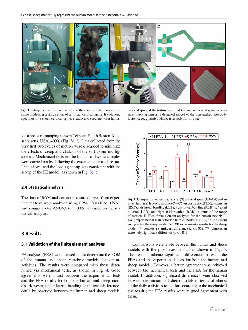
Fig. 3 Set-up for the mechanical tests on the sheep and human cervicalspine models: a testing set-up of an intact cervical spine; b cadavericspecimen of a sheep cervical spine; c cadaveric specimen of a human
cervical spine; d the testing set-up of the fusion cervical spine; e pres-sure mapping sensor; f designed model of the non-grafted interbodyfusion cage; g printed PEEK interbody fusion cage
via a pressure-mapping sensor (Tekscan, South Boston,Mas-sachusetts, USA, 4000) (Fig. 3d, f). Data collected from thevery first two cycles of motion were discarded to minimizethe effects of creep and chalasis of the soft tissue and lig-aments. Mechanical tests on the human cadaveric sampleswere carried out by following the exact same procedure out-lined above, and the loading set-up was consistent with theset-up of the FE model, as shown in Fig. 3c, e.
2.4 Statistical analysis
The data of ROM and contact pressure derived from exper-imental tests were analysed using SPSS 18.0 (IBM, USA),and a single factor ANOVA (α �0.05) was used for the sta-tistical analysis.
3 Results
3.1 Validation of the finite element analyses
FE analyses (FEA) were carried out to determine the ROMof the human and sheep vertebrae models for variousactivities. The results were compared with those deter-mined via mechanical tests, as shown in Fig. 4. Goodagreements were found between the experimental testsand the FEA results for both the human and sheep mod-els. However, under lateral bending, significant differencescould be observed between the human and sheep models.
Fig. 4 Comparison of an intact sheep (S) cervical spine (C3–C4) and anintact human (H) cervical spine (C4–C5) under flexion (FLX), extension(EXT), left lateral bending (LLB), right lateral bending (RLB), left axialrotation (LAR), and right axial rotation (RAR) in terms of the rangeof motion. H-FEA, finite element analyses for the human model; H-EXP, experimental results for the human model; S-FEA, finite elementanalyses for the sheep model; S-EXP, experimental results for the sheepmodel. ‘*’ denotes a significant difference (p <0.05); ‘**’ denotes anextremely significant difference (p <0.01)
Comparisons were made between the human and sheepmodels with the prostheses in situ, as shown in Fig. 5.The results indicate significant differences between theFEAs and the experimental tests for both the human andsheep models. However, a better agreement was achievedbetween the mechanical tests and the FEA for the humanmodel. In addition, significant differences were observedbetween the human and sheep models in terms of almostall the daily activities tested for according to the mechanicaltest results; the FEA results were in good agreement withthem.
123
L. Wang et al.
Fig. 5 Comparisons of the biomechanical behaviours of the human andsheep models under flexion (FLX), extension (EXT), left lateral bend-ing (LLB), right lateral bending (RLB), left axial rotation (LAR), andright axial rotation (RAR) with respect to a their range of motion andb the maximum von Mises stress of the superior endplate of the lower
vertebra. H-FEA, finite element analyses for the human model; H-EXP,experimental results for the human model; S-FEA, finite element anal-yses for the sheep model; S-EXP, experimental results for the sheepmodel. ‘*’ denotes a significant difference (p <0.05); ‘**’ denotes anextremely significant difference (p <0.01)
Fig. 6 Comparisons of thebiomechanical behaviours of thehuman and sheep models underflexion (FLX), extension (EXT),left lateral bending (LLB), rightlateral bending (RLB), left axialrotation (LAR), and right axialrotation (RAR) with respect to atheir range of motion and b themaximum von Mises stress ofthe inferior endplate of theupper vertebra
3.2 Biomechanical characterizationof the differences between the humanand sheepmodels
Based on previous validated FE models of human and sheepcervical spine systems with artificial fusion cages insertedinto them, the biomechanics of the fusion models were stud-ied by employing two types of fusion cage: a flat one anda curved one. The differences between the two species interms of their ROM and the stresses generated in both end-plates were determined (Fig. 6).
Compared with the intact model, the fusion model wasfound to have a smaller ROM for both the human and sheepmodels. For the flat cage group, the ROM for the sheep fusionmodel was 2.42°–8.18°, whereas the ROM for the humanfusionmodel was 0.75°–2.45°, which is from one to six timesthat of the sheep model. For the curved cage group, the ROMfor the sheep fusion model was 1.24°–2.48°, whereas theROM for the human fusion model was 0.58°–1.77°, whichis from one to three times that of the sheep model. Signifi-cant differenceswere observed between the sheep and humanmodels in the lateral bending activities; however, minimumvariance was found between the two species during flexion
and extension. Even for the same species, e.g. in the sheepmodel, the flat cage was associated with one to four timesthe ROM of that of the curved cage model. However, in thehuman model, the flat cage showed from one to two timesthe ROM of the curved one.
Comparedwith the intactmodel, higher stresseswere gen-erated in the fusion model for both human and sheep. For theflat cage group, the von Mises stresses on the endplates were33–84MPa in the sheep model and 13–29MPa in the humanmodel. The maximum variance of the stresses on the end-plates was predicted in the human and sheep models underlateral bending. The stresses generated in the sheep modelwere 1.7–3.4 times those of the human model. However,minimum variance was found between the two species interms of the stresses generated on the endplates under flex-ion/extension.
For the curved cage group, the von Mises stresses gener-ated on the endplates were 21–40 MPa for the sheep modeland 8–18 MPa for the human model, which is from twoto four times that of the sheep model. Moreover, the max-imum variance was found between the two species in termsof the stresses on the endplates under flexion/extension, but
123
Can the sheep model fully represent the human model for the functional evaluation of…
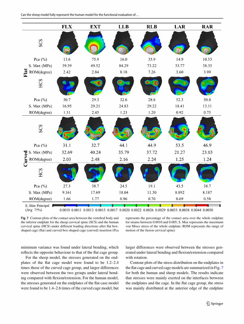
Fig. 7 Contour plots of the contact area between the vertebral body andthe inferior endplate for the sheep cervical spine (SCS) and the humancervical spine (HCS) under different loading directions after flat box-shaped cage (flat) and curved box-shaped cage (curved) insertion (Pca
represents the percentage of the contact area over the whole endplatefor strains between 0.0010 and 0.005; S. Max represents the maximumvon Mises stress of the whole endplate; ROM represents the range ofmotion of the fusion cervical spine)
minimum variance was found under lateral bending, whichreflects the opposite behaviour to that of the flat cage group.
For the sheep model, the stresses generated on the end-plates of the flat cage model were found to be 1.2–2.4times those of the curved cage group, and larger differenceswere observed between the two groups under lateral bend-ing compared with flexion/extension. For the human model,the stresses generated on the endplates of the flat case modelwere found to be 1.4–2.6 times of the curved cage model, but
larger differences were observed between the stresses gen-erated under lateral bending and flexion/extension comparedwith rotation.
Contour plots of the stress distribution on the endplates inthe flat cage and curved cagemodels are summarized in Fig. 7for both the human and sheep models. The results indicatethat stresses were mainly exerted on the interfaces betweenthe endplates and the cage. In the flat cage group, the stresswas mainly distributed at the anterior edge of the endplate
123
L. Wang et al.
for the sheep model, whereas it was mainly distributed at theposterior and anterior edges of the endplate for the humanmodel. In the curved cage group, the stress was mainly gen-erated in the anterior region of the endplates for the sheepmodel, whereas it was in the outskirt region of the endplatesfor the human model. Overall, for both species, the curvedmodel offered more evenly distributed stresses than the flatmodel.
It has been reported in the literature that the osteoblastand osteoclast can maintain balance when the applied micro-strain is within the range of 1000–1500 μ 2(Duncan andTurner 1995; Frost 1987). Therefore, micro-strains withinthat range were presented in the contour plots for both end-plates in Fig. 7. In addition, the percentage of the effectivestrain area over the total area of the endplate was calculated(Pca) to denote the possible bone in-growth area.
4 Discussion
Animal tests and the sheep model in particular have nor-mally been employed to evaluate the functional performanceand viability of fusion cage prostheses for cervical spinefusion (Drespe et al. 2005). However, large differences existbetween the sheep and human species in terms of the geomet-rical characteristics and the biomechanics of their cervicalspine systems, and differences in the normal daily activi-ties between the two species make it rather difficult for thesheep model to fully represent a human model. FE modelsof both species were constructed to characterize the biome-chanical/kinematics differences between the two species interms of range of motion and contact stresses. In addition,the fusedmodel with designed flat/curved spinal discs placedin situ was also studied for both species to gain better insightinto the fitness performance of the sheep model when usedfor the design and evaluation of human prostheses.
Significant differences were found between the humanspinal disc and the ovine spinal disc with respect to theirgeometrical characteristics (Kandziora et al. 2001b). Thesedifferences might be exacerbated by the rather larger ROMof the daily activities of sheep compared with those ofhumans. Among all the activities considered, lateral bending(LLB/RLB) is the most representative motion to distinguishthe sheep model from the human model, where the ROM ofthe former is nearly four times that of the latter, as shownin the experimental results obtained from the intact modelsof the two species. For flexion–extension (FLX/EXT), theROM of the sheep model is predicted to be 1.5 times thatof the human model. However, in terms of internal/externalrotation, both species have similar a ROM. The differencesbetween the two species were amplified after the fusionsurgery, as determined from the fusionmodelwith the naturalspinal disc replaced by a 3D-printed PEEKcage. For all kinds
of motions, the ROM of the human fusion spine model wasreduced to almost zero. In comparison, the ROMof the sheepfusionmodelwas reduced to 70%for lateral bending and60%for flexion–extension, and the ROM for internal/externalrotation remained similar to that of the intact sheep model(Fig. 5). In addition to the results obtained for the ROMs,the stresses generated in the superior endplate of the humanfusion model were found to be 50% of those in the sheepmodel for flexion/extension and 40% for internal/externalrotation, whereas they were found to be 60% for the lateralbending movement. Therefore, extremely large differencesexisted between the two species with respect to the fusionmodel, which may clearly explain the smaller fusion ratesreported in the literature to be 33.3–83.3% (Li et al. 2014;Schreiner et al. 2007; Slivka et al. 2006) for the sheep modelcompared with those for the human model (89.7–97.9%)(Cauthen et al. 2003; Hacker et al. 2000; Moreland et al.2004). Thus, the sheep model represents the worst-case sce-nariowhen employed for the functional evaluationof fusionalprostheses.
Moreover, two fusion disc designs, a flat one and a curvedone, were employed to investigate the effectiveness of thesheep model for representing the human model for the func-tional evaluation of different fusion disc designs. The resultsindicate that the different designs caused no significant differ-ences in the human fusion model with respect to the ROMs.However, a dramatic drop (75%) was observed in the ROMsfor the curved design compared with the flat design in thesheep fusionmodel (Fig. 6). This means that the sheepmodelcould be really sensitive to disc design, and the curved discwas associated with better fusion performance than the flatdisc Therefore, with respect to ROM, the sheep model maynot accurately represent the human model.
When comparing the predicted maximum von Misesstresses exerted to the inferior endplate of the upper ver-tebra for the fused models of the two species with the twodesigns, similar trends were found in the human as well asin the sheep fusion model with respect to the effects of thefusion cage. In the human model, the curved disc was asso-ciated with smaller stresses compared with the flat one: a50% drop for flexion/extension, a 60% drop for lateral bend-ing, and a 30–40% drop for internal/external rotation wereobserved (Fig. 6). This indicates that both the human andsheep models are sensitive to the design of the fusion bodywith respect to the von Mises stresses generated in the hostbone, which makes the sheep model a fairly good candi-date for animal studies on the functional evaluation of fusionprostheses in the spine. However, the larger magnitude of thestresses exerted in the sheep fusion model can also increasethe effect of osteoclasts and consequently cause the failure ofthe evaluated prostheses. In such cases, more caution shouldbe exercised when using the sheep model to evaluate thefunctional biomechanical performance of a fusion body, and
123
Can the sheep model fully represent the human model for the functional evaluation of…
a design with a better fit to the intact residual bone may pro-vide fairly better representative results.
In the sheep model, similar trends but relatively smallerdrops were found for all kinds of activities. In addition, thepredicted effective contact area (Pca) between the vertebralbody and the inferior endplate in the sheep fusion model wasfound to be quite sensitive to the design used (Fig. 7); thecurved design is the more favourable one and is associatedwith a Pca three to four times that of the flat design. Whereasthe differences between the two designs in the human fusionmodel were not as significant as those in the sheep model,the curved one is associated with a Pca less than 30% ofthat for the flat design for some movements. The sensitivityof the fusion model to different designs of the fusion cagewas extremely amplified in the sheepmodel,whichmakes thesheepmodel a very good indicator of the better design.On theother hand, the extremely enlarged magnitude of the stressesand contact area may also contribute to the loosening andsubsidence of the fusion body. Researchers must be awareof the conflicts between the benefits and disadvantages ofthe application of the sheep model to make more pertinentevaluations for pre-clinical tests.
There were certain limitations in the present study. First,the models studied here include only two adjacent cervicalspinal discs instead of the complete cervical spine system,consequently neglecting the effects of the neighbouring com-ponents. Secondly, the stiffness andmodulus of the ligamentsassociated with the cervical spine system studied here weretaken from the literature; therefore, the effects that result fromthe gait characteristics of daily activitieswere not considered,which might have caused a certain degree of prediction errorin our biomechanics characterizations.
5 Conclusions
In this study, the biomechanical characteristics of the cer-vical spine systems of the sheep and human species werestudied and compared to quantify the effectiveness of thesheep model for representing the human model during thefunctional evaluation of fusion cage protheses. Owing to thesignificantly large differences between the two species withrespect to their geometrical characteristics and themotions ofdaily activities, the sheepmodelmay represent theworst-casescenario of the human model with exaggerated stresses, con-tact area, and ranges of motion.Moreover, the sheepmodel ismuch more sensitive to differences in prostheses design thanthe human model, which means that the sheep model mightprovide a rather amplified effect for the biomechanical per-formance of different designs. Caution should be exercisedwhen the sheep is used as the animal model for the functionalevaluation of various designs, and the finite element modelsbuilt in this study can be employed as an effective method-
ology for the performance evaluation of cage prostheses ofthe cervical spine.
Acknowledgements The work was supported by the Program of theNationalNatural Science Foundation ofChina [51675411], theNationalKey R&D Program of China [2018YFB1107000], the Key Program ofinternational cooperation in Shaanxi Province [2017KW-ZD-02] andthe Fundamental Research Funds for the Central Universities.
Open Access This article is distributed under the terms of the CreativeCommons Attribution 4.0 International License (http://creativecommons.org/licenses/by/4.0/), which permits unrestricted use, distribution,and reproduction in any medium, provided you give appropriate creditto the original author(s) and the source, provide a link to the CreativeCommons license, and indicate if changes were made.
References
Cauthen JC, Theis RP, Allen AT (2003) Anterior cervical fusion: acomparison of cage, dowel and dowel-plate constructs. Spine J3:106–117
DaentzerD,WelkeB,HurschlerC,HusmannN, JansenC, FlammeCH,Richter BI (2015) In vitro -analysis of kinematics and intradiscalpressures in cervical arthroplasty versus fusion—a biomechani-cal study in a sheep model with two semi-constrained prosthesis.Biomedical Engineering Online 14:1–15
DeVries NA (2011) The biomechanics of the sheep cervical spine: anexperimental and finite element analysis. University of Iowa, Iowa
DeVries NA, Gandhi AA, Fredericks DC, Grosland NM, Smucker JD(2012)Biomechanical analysis of the intact and destabilized sheepcervical spine. Spine (Phila Pa 1976) 37:E957–E963. https://doi.org/10.1097/brs.0b013e3182512425
Duncan RL, Turner CH (1995) Mechanotransduction and the func-tional response of bone to mechanical strain. Calcif Tissue Int57:344–358
FaizanA et al (2012) Do design variations in the artificial disc influencecervical spine biomechanics? A finite element investigation. EurSpine J 21:653–662
Frost HM (1987) Bone “mass” and the “mechanostat”: a proposal. AnatRec 219:1–9. https://doi.org/10.1002/ar.1092190104
Galbusera F, Fantigrossi A, Raimondi MT, Sassi M, Fornari M, Assi-etti R (2006) Biomechanics of the C5–C6 spinal unit before andafter placement of a disc prosthesis. BiomechModelMechanobiol5:253–261. https://doi.org/10.1007/s10237-006-0015-4
Ha SK (2006) Finite element modeling of multi-level cervical spinalsegments (C3–C6) and biomechanical analysis of an elastomer-type prosthetic disc. Med Eng Phys 28:534–541. https://doi.org/10.1016/j.medengphy.2005.09.006
Hacker RJ, Cauthen JC, Gilbert TJ, Griffith SL (2000) A prospectiverandomized multicenter clinical evaluation of an anterior cervicalfusion cage. Spine (Phila Pa 1976) 25:2646–2654
Hong X, Wu XT, Zhuang SY, Bao JP, Shi R (2014) New cage forposterior minimally invasive lumbar interbody fusion: a studyin vitro and in vivo. Orthop Surg 6:47–53. https://doi.org/10.1111/os.12083
Kallemeyn N, Gandhi A, Kode S, Shivanna K, Smucker J, GroslandN (2010) Validation of a C2–C7 cervical spine finite elementmodel using specimen-specific flexibility data. Med Eng Phys32:482–489. https://doi.org/10.1016/j.medengphy.2010.03.001
Kandziora F, Pflugmacher R, Schafer J, Born C, Duda G, Haas NP,Mittlmeier T (2001a)Biomechanical comparison of cervical spineinterbody fusion cages. Spine (Phila Pa 1976) 26:1850–1857
Kandziora F, PflugmacherR, ScholzM, SchnakeK, LuckeM, SchroderR, Mittlmeier T (2001b) Comparison between sheep and humancervical spines—an anatomic, radiographic, bonemineral density,and biomechanical study. Spine 26:1028–1037. https://doi.org/10.1097/00007632-200105010-00008
Li Y et al (2014) A polycaprolactone–tricalcium phosphate com-posite scaffold as an autograft-free spinal fusion cage in asheep model. Biomaterials 35:5647–5659. https://doi.org/10.1016/j.biomaterials.2014.03.075
MorelandDB et al (2004)Anterior cervical discectomy and fusionwithimplantable titanium cage: initial impressions, patient outcomesand comparison to fusion with allograft. Spine J 4:184–191
Natarajan RN, Chen BH, An HS, Andersson GB (2000) Anterior cer-vical fusion: a finite element model study on motion segmentstability including the effect of osteoporosis. Spine (Phila Pa 1976)25:955–961
Panzer B, Matthew (2006) Numerical modelling of the human cervicalspine in frontal impact. University of Waterloo, Waterloo
Schreiner U, Scheller G, Chen C, Schwarz M (2007) Introduction ofa new intervertebral spacer for cervical fusion: results of a con-trolled animal study. Z Orthop Unfall 145:736–743
Slivka MA, Spenciner DB, Seim HB 3rd, Welch WC, Serhan HA,Turner AS (2006) High rate of fusion in sheep cervical spinesfollowing anterior interbody surgery with absorbable and nonab-sorbable implant devices. Spine (Phila Pa 1976) 31:2772–2777.https://doi.org/10.1097/01.brs.0000245935.69927.a1
Vadapalli S, Sairyo K, Goel VK, Robon M, Biyani A, KhandhaA, Ebraheim NA (2006) Biomechanical rationale for usingpolyetheretherketone (PEEK) spacers for lumbar interbodyfusion—a finite element study. Spine 31:992–998
Wilke HJ, Kettler A, Claes LE (1997) Are sheep spines a validbiomechanical model for human spines? Spine (Phila Pa 1976)22:2365–2374
Yamada K, Ito M, Akazawa T, Murata M, Yamamoto T, Iwasaki N(2015) A preclinical large animal study on a novel intervertebralfusion cage coveredwith high porosity titaniumsheetswith a triplepore structure used for spinal fusion. Eur Spine J 24:2530–2537.https://doi.org/10.1007/s00586-015-4047-2
Zhang QH, Teo EC, Ng HW, Lee VS (2006) Finite element analy-sis of moment-rotation relationships for human cervical spine.J Biomech 39:189–193. https://doi.org/10.1016/j.jbiomech.2004.10.029
Publisher’s Note Springer Nature remains neutral with regard to juris-dictional claims in published maps and institutional affiliations.