15
2017 Vulcraft Steel Joists & Joist Girders CANADIAN EDITION www.nucor.com www.vulcraft.ca Better Partners. Better Products. Better Outcomes.

2017 VulcraftSteel Joists &
Joist Girders
CANADIAN EDITION
www.nucor.com www.vulcraft.ca
Better Partners. Better Products.Better Outcomes.
2017 Canadian Joist Catalog.indd 1 11/28/16 2:10 PM

2
VULCRAFT: A DIVISION OF NUCOR CORPORATION
Outside of construction circles it may not be well-known that Vulcraft is North America’s largest producer of steel joists, joist girders and steel deck. Vulcraft is a major division of one of the largest steel companies in the United States: Nucor Corporation. Nucor and its subsidiaries are world-renowned for their state-of-the-art steelmaking techniques and unsurpassed quality control, resulting in the highest quality steel products in
the world.
A WORD ABOUT QUALITY
When it comes to manufacturing steel joists,
there can be no compromise on quality. Your
business depends on it. Our reputation and success
depends on it. As the largest manufacturer of steel
joists in North America, all of our projects and all of
our customers depend on Vulcraft for consistently
high standards of quality that are demonstrated in
reliable performance.
In the manufacturing of steel joists and joist
girders, Vulcraft begins with high quality steel
produced primarily by Nucor’s steelmaking
entities. Welding to exact specifications is the key
to making structurally sound joists. This being the
case, Vulcraft welders are certified to Canadian
Welding Bureau (CWB) – W47/W59 standards and
our plants are certified as Div. 1 steel fabricator by
CWB per standard W47.1 and all welds conform to
CSA W59.
To further ensure the precision and quality of
welds, every Vulcraft quality assurance inspector
is also certified to these same high standards. Furthermore, Vulcraft’s quality assurance
Cover photo: CNE Automotive Building - Toronto, ON
Full scale joist load tester
MISSION STATEMENT
The people of Vulcraft are dedicated to the common goal of providing quality steel products and unmatched customer service. That commitment is reflected in the company’s mission statement:
“To take care of our customers by being the safest, highest quality, lowest cost, most productive, and most profitable steel and steel products company in the world. We will accomplish this while being both cultural and environmental stewards in the communities in which we live and work. And we will accomplish this by working together.”
supervisors report directly to the Engineering Manager. Vulcraft employs an ongoing program of mechanical testing that includes full scale load
tests at every facility.
As the leading manufacturer of steel joists and joist girders in North America, Vulcraft’s reputation depends on a successfully managed quality control program. That’s why quality is important at Vulcraft. You have our word on it.
MATERIAL
Steel used in the manufacture of Vulcraft chord and web sections conform to both of the following CSA Specifications of latest adoption:
CSA G40.20 General Requirements for Rolled or Welded Structural Quality Steel
CSA G40.21 Structural Quality Steel
• ANGLES Equal and unequal leg angles are used for the design of open web steel joists. Their applications include chords, webs, bridging and bridging clips.
Material designation: CSA G40.21 55W. • RODS/PLATES Rods and plates are used for the design of open web steel joists. They are used for web members and fillers. Material designation: CSA G40.21 50W,
CSA G40.21 55W or ASTM A36.
• SHEET Sheet conforming to CSSBI is used for the roll forming of steel floor and roof decking. Material Designation: ASTM A653/A653M–00 CAN/CSA-136 and C 22.2 No79
Vulcraft also uses bars and beams for the design
of open web steel joists. Please contact a Vulcraft
sales office for custom engineering solutions.
ENGINEERING
All Vulcraft jobs are designed in accordance
with the latest editions of the National Building
Code of Canada or provincial building codes,
whichever supersede. Steel members are designed
per the latest edition of CAN/CSA S-16.
Vulcraft is a manufacturer of open web
steel joists (OWSJ), joist girders, floor deck and
roof deck. Vulcraft employs a staff of Canadian
Registered Professional Engineers (P. Eng) for the
design, manufacture and marketing of its products.
Vulcraft does not accept the responsibility as the
design professional of record for any structure.
3
4
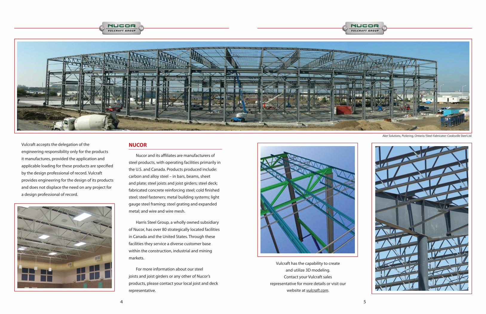
Vulcraft accepts the delegation of the
engineering responsibility only for the products
it manufactures, provided the application and
applicable loading for these products are specified
by the design professional of record. Vulcraft
provides engineering for the design of its products
and does not displace the need on any project for
a design professional of record.
NUCOR
Nucor and its affiliates are manufacturers of
steel products, with operating facilities primarily in
the U.S. and Canada. Products produced include:
carbon and alloy steel – in bars, beams, sheet
and plate; steel joists and joist girders; steel deck;
fabricated concrete reinforcing steel; cold finished
steel; steel fasteners; metal building systems; light
gauge steel framing; steel grating and expanded
metal; and wire and wire mesh.
Harris Steel Group, a wholly owned subsidiary
of Nucor, has over 80 strategically located facilities
in Canada and the United States. Through these
facilities they service a diverse customer base
within the construction, industrial and mining
markets.
For more information about our steel
joists and joist girders or any other of Nucor’s
products, please contact your local joist and deck
representative.
5
Aker Solutions, Pickering, Ontario/Steel-Fabricator: Cooksville Steel Ltd.
Vulcraft has the capability to create
and utilize 3D modeling.
Contact your Vulcraft sales
representative for more details or visit our
website at vulcraft.com.

6
Nucor Corporation is North America’s largest recycler, using almost 13 million tons of scrap steel in 2012 to create new products. Nucor uses Electric Arc Furnace (EAF) technology at all of its steel producing facilities. EAFs use post-consumer scrap steel material for the major feedstock, unlike blast furnace operations which use mined iron ore as the major feedstock.
2012 RECYCLED CONTENT OF NUCOR STEEL PRODUCTS FOR THE L.E.E.D.® PROGRAM Nucor has prepared the following information to help calculate the recycled
content for products being used with “Green Building” applications or for projects in the L.E.E.D. program. Percentages are approximate and based on the total weight of the products. Calculations are based on 2012 scrap steel delivered and finished materials produced and are defined in accordance with ISO 14021:1999. Values do not consider home scrap or scrap generated onsite. Specific product information may be available from facility representatives.
BAR MILL GROUP - Darlington, SC; Norfolk, NE; Jewett, TX; Plymouth, UT; Auburn, NY; Birmingham, AL; Kankakee, IL; Jackson, MS; Seattle, WA; Marion, OH; and Memphis, TN
2012 Approximate Recycled Steel Content Of All Nucor Bar Mill Group Products(*) Facility Total Scrap Total Alloys and Total Post Consumer Total Pre-consumer Steel Use Other Iron Units Recycled Content Recycled Content
All 99.9% 0.1% 83% 17%
The Nucor Bar Mill Group produces rebar, angles, flats, rounds and other miscellaneous shapes. The bar mill group uses recycled scrap steel for over 99.9% of the feedstock.
(*)Studies show that the recycled steel used for Nucor products consists of approximately 83% post-consumer scrap. The remaining 17% typically consists of pre-consumer scrap generated by manufacturing processes for products made with steel.
Nucor Bar Products 99.9%Nucor Sheet Products 75.7%Total Nucor Steel Combined 91.4%Vulcraft Structural Products 99.9%Vulcraft Decking 75.7%
Product Group Average Recycled Content
2012 Recycled Steel Content of Nucor Products(*)(% by Total Weight)
7
SHEET MILL GROUP - Crawfordsville, IN; Hickman, AR; Berkeley, SC; and Decatur, AL
The Nucor Sheet Mill Group produces hot band, cold rolled, pickled and galvanized products. Nucor Sheet mills use varying amounts of recycled materials depending on metallurgical product demands and market conditions. The combined sheet mill total recycled content is approximately 75.7%.
VULCRAFT GROUP - Florence, SC; Norfolk, NE; Brigham City, UT; Grapeland, TX; St. Joe, IN; Fort Payne, AL; and Chemung, NY
JOISTS - The bar steel for over 95% of Vulcraft joists is obtained from one of the nine Nucor bar mills that use over 99% scrap steel as their feedstock. A breakdown of the recycled content of Nucor bar mill products is detailed above. Vulcraft facilities may receive steel from sources outside of Nucor that may contain lower amounts of recycled steel. Specific product information is available from facility representatives.
DECK - Steel for decking produced by Vulcraft facilities are typically obtained from one of the four Nucor sheet mills. A breakdown of the recycled content of Nucor sheet mill products is detailed above. Vulcraft deck products contain approximately 75.7% recycled steel.
Additional information is available online through the Steel Recycling Institute at recycle-steel.org.
(*)Studies show that the recycled steel used for Nucor products consists of approximately 83% post-consumer scrap. The remaining 17% typically consists of pre-consumer scrap generated by manufacturing processes for products made with steel.
All figures shown are based on 2012 figures and may vary from year to year. Please contact your local sales representative for current average recycled content for Vulcraft products.
2012 Approximate Recycled Steel Content of Nucor Sheet Mill Group Products(*)
Facility
Crawfordsville, IN
Hickman, AR
Berkley, SC
Decatur, AL
Total ScrapSteel Used
95.4%
71.0%
64.1%
72.5%
Total Alloys andOther Iron Units
4.6%
29.0%
35.9%
27.5%
Total Post ConsumerRecycled Content
79.2%
58.9%
53.2%
60.2%
Total Pre-consumerRecycled Content
16.2%
12.1%
10.9%
12.3%
Go Transit Bus Garage Bramalea, ON/Steel Fabricator: Quad Steel Inc.

8
STEEL JOIST INTRODUCTION
The Vulcraft open web steel joist and joist girder system is an effective and economical solution for floor and roof systems in industrial and commercial buildings. Capable of supporting loads over short and long spans alike, Vulcraft joist and joist girders makes the erection of buildings safer, easier and inexpensive. With more material efficiency, Vulcraft joists can reduce roof and floor self weights to allow columns and foundations to be lighter resulting in overall building economy.
The figure below displays typical open web steel joists and their components with typical dimensions. The top and bottom chords consists of two back to back angles typically with a 25 mm (1”) gap in between the angles. Depending on the size of the web members that gap may be smaller or larger. Web members are comprised of rods, crimped single angles, double angles of various diameters or leg sizes depending on the joist depth and loading conditions.
Note: Actual layout may vary
RODWEB
TOP CHORD
BOTTOM CHORD
JOIST BEARING SEAT
CRIMPEDANGLEWEB
DOUBLEANGLEWEB
EXTENDED END
VARIES
END PANEL
D
25mm (1”)
D
25mm (1”)
D
WEB MEMBER
9
STANDARD JOIST TYPES
Open web steel joists can be furnished with either underslung or square ends, with parallel chords or with single or double pitched top chords to provide sufficient slope for roof drainage. The depth defined for an open web steel joist refers to the depth at the center of the span, except for offset double pitched joist, where the depth should be given at the ridge along with the location of the ridge. All pitched joist will be cambered in addition to the pitch unless specified otherwise.
For optimum depth consult Vulcraft or specify on drawings a maximum allowable depth and Vulcraft will determine the most economical depth given project criteria.
CAMBER
Standard Types: The camber under section 16.5.14 of CAN/CSA S-16 (0.2% of the span) will be fabricated into the joists unless the design professional specifically states otherwise on the structural drawings. Special camber is intended to offset dead load deflections, the amount of camber is only as accurate as the dead loads given on the structural drawings. Non-Standard Types: The design professional shall provide on the structural drawings the amount of camber desired. If camber is not specified, Vulcraft will use a standard camber value or possibly no camber for certain scissor, arched, bowstring, or gable profiles.
NON-STANDARD JOIST TYPES
The following joists can also be supplied by Vulcraft, however, the district sales office or manufacturing facility nearest you should be contacted for possible limitations in depth or length.
* Contact Vulcraft for minimum depth at ends.

STANDARD LOAD TYPES
Vulcraft will design joists based on the requirements from CISC S-16 and the loading conditions specified on the structural design documents. When specifying loads, the design professional must classify them according to Canadian standards as dead, live, seismic, snow, or wind. Vulcraft will apply the necessary load combinations in accordance with the building code defined on the structural design documents to obtain a worst case loading condition and size members accordingly. Unless noted otherwise on structural documents, Vulcraft will assume that the specified dead loads include the self-weight of the joists.
** If concentrated load location is not known at the time of design, (i.e. RTU locations) specify whether the load is to be applied at the top or bottom chord with the magnitude and range where load could possibly be located and Vulcraft will design the joist for that load applied at any panel point within the specified range.
UPLIFT: Where uplift forces due to wind are a design requirement, these forces shall be indicated
on the structural design documents in terms of factored NET uplift in kilopascals or pounds per square foot. When these forces are specified, they shall be considered in the design of joists and/or bridging. An additional line of bottom chord bridging shall be provided near the first bottom chord panel points whenever uplift due to wind forces is a design consideration.
SPECIAL DEFLECTION
The deflection criteria to be considered must be shown on the structural design documents. Appendix D of the CAN/CSA S-16 standard provides recommended deflection limits given the building type.
Note: Appendix D1 states that although the criteria refer to specified live and wind loads, the designer should consider the inclusion of specified dead loads in some instances. For example, non-permanent partitions, which are classified by the National Building Code as dead load, should be part of the loading considered under Appendix D if they are likely to be applied to the structure after the completion of finishes susceptible to cracking.
10
Building Specified type loading Application Maximum
Live Member supporting L/240 inelastic roof coverings
Live Member supporting L/180 elastic roof coverings
Live Member supporting L/300 floors
Maximum Crane runway girders for wheel crane capacity of L/800 (no impact) 225 kN and over
Maximum Crane runway girders for wheel loads crane capacity of L/600 (no impact) under 225 kN
Members of floors and roofs supporting Live construction and L/360 finishes susceptible to cracking
Members of floors and roofs supporting Live construction and L/300 finishes not susceptible to cracking
Industrial
AllOthers
UNIFORM LOAD
CONCENTRATED LOADS**
SNOW DRIFT
PARTIAL LOADS
AXIAL LOADS
MOMENT LOADS
11
(a) Extended top chords or full depth cantilever ends require the special attention of the specifying professional. Loading and deflection requirements should be properly indicated on structural drawings.
JOIST BEARING DETAILS
ANCHORAGE TO STEEL ANCHORAGE TO MASONRY BOLTED CONNECTIONTypically required at columns
MAXIMUM LENGTH 3M (10’- 0”)
TOP CHORD EXTENSIONSee Note (a)
SQUARE ENDCross bridging required near the
end of bottom bearing joist.
HEADERSNote: If header does not bear at a Joist Panel
Point add extra web in field as shown.EW or Panel Point by Vulcraft
Staggered Joists
102 mm Gage22mm Holesfor 19mm bolts
4” Gage13/16 inch Holesfor 3/4” bolts
min 64 mm (2 1/2”)bearing
In order to avoid work point eccentricity moments to the top chord it is necessary to obtain sufficient bearing at each end of the joist. Minimum bearing requirements can vary depending on end reactions and joist geometry. A minimum bearing length of 64mm (2 1/2”) is acceptable for joists less than 750mm (30”) deep, spanning 9000mm (30’) or less, with an end reaction less than 45kN (10 kips). Depending on the width of the support, joist may need to be staggered, as shown in Figure 1 if 64 mm (2 1/2”) minimum bearing length cannot be achieved when joists are in line or if end reactions demand a longer bearing length.

JOIST SEATS
Joist seats can vary in dimension depending on the reactions of the joist. Larger end reactions require bigger chords and end web members that need to come together with the joist bearing seats. The most common seat depth utilized is 100 mm (4”) on joists and 190 mm (7 1/2”) for joist girders. Heavily loaded joist and joist girders may demand 125 mm (5”) and 250 mm (10”) respectively, depending on the chord sizes and end webs. When sloped seats are present in pitched chords, the depth of the seat is not uniform along the top chord. It is common practice to communicate the desired condition on contract drawings by defining
a seat depth at the gridline of the bay or centerline of the supporting member. Consult Vulcraft for any special seat conditions (i.e. flush or highly sloped seats).
12 13
Full Depth Cantilever
Tie Joist with Stabilizer Plate Tie Joist With Angle (NOT RECOMMENDED)
TIE JOIST
Tie joists located at or near columns will require a bottom chord extension to the bearing support member. The typical detail used is a standard bolted connection at the seat, with a 19mm (3/4”) stabilizer plate welded to the column
for the bottom chord angles to slip into during erection to prevent overturning of the joist. If bottom chord extension is to be bolted or welded, the specifying professional must provide the corresponding axial loads on structural drawings.
For joist with full depth cantilevered end(s), the specifying professional must clearly show or specify whether the cantilevered end(s) bears on the structural support at the top or bottom chord of the cantilevered end(s).
Sloped Seats
Varying depths,specify depth atreference point(i.e. Gridline)
19 mm (3/4”) Stabilizer Plate*this detail can be provided at an additional cost
Joist Span, mm (ft) Number of Bridging Rows of Roof Joist
1 Row Horiz (Top & Bottom) + 2 Uplift Rows (Bottom Only)2 Rows Horiz (Top & Bottom) + 2 Uplift Rows (Bottom Only) 3 Rows Horiz (Top & Bottom) + 2 Uplift Rows (Bottom Only)
2 Rows Horiz (Top & Bottom) Plus 1 Bolted “X” + 2 Uplift Rows (Bottom Only) 2 Rows Horiz (Top & Bottom) Plus 2 Bolted “X” + 2 Uplift Rows (Bottom Only)
All Bolted “X” at 4000mm (13’) Apart Max. + 2 Uplift Rows (Bottom Only)
< 4600 (15)4600 - 9800 (15-32)
9800 - 13800 (32 - 45)13800 - 15300 (45 - 50)15300 - 18300 (50 - 60)
> 18300 (60)
Joist Span, mm (ft) Number of Bridging Rows of Floor Joist
1 Row Horiz (Top & Bottom) 2 Rows Horiz (Top & Bottom) 3 Rows Horiz (Top & Bottom)
2 Rows Horiz (Top & Bottom) Plus 1 Bolted “X” 2 Rows Horiz (Top & Bottom) Plus 2 Bolted “X”
All Bolted “X” at 4000mm (13’) Apart Max.
< 4600 (15)4600 - 9800 (15-32)
9800 - 13800 (32 - 45)13800 - 15300 (45 - 50)15300 - 18300 (50 - 60)
> 18300 (60)
Estimate of Number of Bridging Line
BRIDGING
Vulcraft follows the bridging requirements from CAN/CSA S-16 clause 16.7. Bridging aids in the lateral stability of joists and it shall not be considered as “bracing”. All bridging shall be installed and anchored prior to the application of construction loads on the joists. Bridging rows shall be spaced such that the unbraced length of the joist chord members between bridging rows or between laterally supported ends and first bridging rows does not exceed: • 170 x ry-y for chords in compression • 240 x ry-y for chords in tension Bridging is most commonly installed in rows as horizontal bridging spanning perpendicular to joists and connected at the joist top and bottom chords. When joists span 13.7m (45’) or more, diagonal bridging rows will need to be installed for erection stability purposes.
Diagonal bridging rows connect from the topchord of joists to the bottom chord of adjacent joists with a bolted or welded connection where the bridging members cross. Once the deck has been installed the top chord of the joist is considered to be laterally stayed by the deck where the rigidity of deck bearing joints must be verified. The unbraced length of bridging members shall not exceed: • 300 x rz for Horizontal Bridging • 200 x rz for Diagonal Bridging Clause 16.7.6 states that the attachment of diagonal or horizontal bridging to joist chords shall be by welding or mechanical means capable of resisting an axial load of at least 3kN (670 lbs) in the attached bridging member. When uplift forces are of design consideration (i.e roof joists) one row of horizontal bridging shall be installed near each first bottom chord panel point.
Note: Must have cross bridging near support
14 15
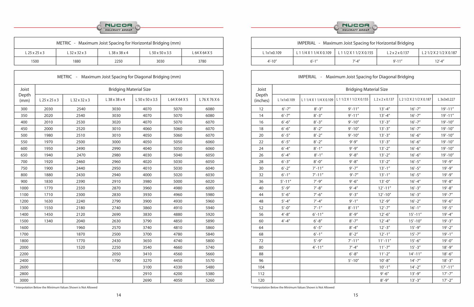
METRIC - Maximum Joist Spacing for Horizontal Bridging (mm)
Joist Depth (mm)
L 32 x 32 x 3 L 25 x 25 x 3
L 25 x 25 x 3 L 32 x 32 x 3 L 38 x 38 x 4 L 50 x 50 x 3.5 L 64 X 64 X 5 L 76 X 76 X 6
L 38 x 38 x 4
Bridging Material Size
L 50 x 50 x 3.5 L 64 X 64 X 5
1500 1880 2250 3030 3780
METRIC - Maximum Joist Spacing for Diagonal Bridging (mm)
* Interpolation Below the Minimum Values Shown is Not Allowed
300 2030 2540 3030 4070 5070 6080
350 2020 2540 3030 4070 5070 6080
400 2010 2530 3020 4070 5070 6070
450 2000 2520 3010 4060 5060 6070
500 1980 2510 3010 4050 5060 6070
550 1970 2500 3000 4050 5050 6060
600 1950 2490 2990 4040 5050 6060
650 1940 2470 2980 4030 5040 6050
700 1920 2460 2960 4020 5030 6050
750 1900 2440 2950 4010 5030 6040
800 1880 2430 2940 4000 5020 6030
900 1830 2390 2910 3980 5000 6020
1000 1770 2350 2870 3960 4980 6000
1100 1710 2300 2830 3930 4960 5980
1200 1630 2240 2790 3900 4930 5960
1300 1550 2180 2740 3860 4910 5940
1400 1450 2120 2690 3830 4880 5920
1500 1340 2040 2630 3790 4850 5890
1600 1960 2570 3740 4810 5860
1700 1870 2500 3700 4780 5840
1800 1770 2430 3650 4740 5800
2000 1520 2250 3540 4660 5740
2200 2050 3410 4560 5660
2400 1790 3270 4450 5570
2600 3100 4330 5480
2800 2910 4200 5380
3000 2690 4050 5260
IMPERIAL - Maximum Joist Spacing for Horizontal Bridging
Joist Depth
(inches)
L 1 1/4 X 1 1/4 X 0.109 L 1x1x0.109
L 1x1x0.109 L 1 1/4 X 1 1/4 X 0.109 L 1 1/2 X 1 1/2 X 0.155 L 2 x 2 x 0.137 L 2 1/2 X 2 1/2 X 0.187 L 3x3x0.227
L 1 1/2 X 1 1/2 X 0.155
Bridging Material Size
L 2 x 2 x 0.137 L 2 1/2 X 2 1/2 X 0.187
4’-10” 6’-1” 7’-4” 9’-11” 12’-4”
IMPERIAL - Maximum Joist Spacing for Diagonal Bridging
* Interpolation Below the Minimum Values Shown is Not Allowed
12 6’ -7’’ 8’ -3’’ 9’ -11’’ 13’ -4’’ 16’ -7’’ 19’ -11’’
14 6’ -7’’ 8’ -3’’ 9’ -11’’ 13’ -4’’ 16’ -7’’ 19’ -11’’
16 6’ -6’’ 8’ -3’’ 9’ -10’’ 13’ -3’’ 16’ -7’’ 19’ -10’’
18 6’ -6’’ 8’ -2’’ 9’ -10’’ 13’ -3’’ 16’ -7’’ 19’ -10’’
20 6’ -5’’ 8’ -2’’ 9’ -10’’ 13’ -3’’ 16’ -6’’ 19’ -10’’
22 6’ -5’’ 8’ -2’’ 9’-9’’ 13’ -3’’ 16’ -6’’ 19’ -10’’
24 6’ -4’’ 8’ -1’’ 9’ -9’’ 13’ -2’’ 16’ -6’’ 19’ -10’’
26 6’ -4’’ 8’ -1’’ 9’ -8’’ 13’ -2’’ 16’ -6’’ 19’ -10’’
28 6’ -3’’ 8’ -0’’ 9’ -8’’ 13’ -2’’ 16’ -5’’ 19’ -9’’
30 6’ -2’’ 7’ -11’’ 9’ -7’’ 13’ -1’’ 16’ -5’’ 19’ -9’’
32 6’ -1’’ 7’ -11’’ 9’ -7’’ 13’ -1’’ 16’ -5’’ 19’ -9’’
36 5’ -11’’ 7’ -9’’ 9’ -6’’ 13’ -0’’ 16’ -4’’ 19’ -8’’
40 5’ -9’’ 7’ -8’’ 9’ -4’’ 12’ -11’’ 16’ -3’’ 19’ -8’’
44 5’ -6’’ 7’ -6’’ 9’ -3’’ 12’ -10’’ 16’ -3’’ 19’ -7’’
48 5’ -4’’ 7’ -4’’ 9’ -1’’ 12’ -9’’ 16’ -2’’ 19’ -6’’
52 5’ -0’’ 7’ -1’’ 8’ -11’’ 12’ -7’’ 16’ -1’’ 19’ -5’’
56 4’ -8’’ 6’ -11’’ 8’ -9’’ 12’ -6’’ 15’ -11’’ 19’ -4’’
60 4’ -4’’ 6’ -8’’ 8’ -7’’ 12’ -4’’ 15’ -10’’ 19’ -3’’
64 6’ -5’’ 8’ -4’’ 12’ -3’’ 15’ -9’’ 19’ -2’’
68 6’ -1’’ 8’ -2’’ 12’ -1’’ 15’ -7’’ 19’ -1’’
72 5’ -9’’ 7’ -11’’ 11’ -11’’ 15’ -6’’ 19’ -0’’
80 4’ -11’’ 7’ -4’’ 11’ -7’’ 15’ -3’’ 18’ -9’’
88 6’ -8’’ 11’ -2’’ 14’ -11’’ 18’ -6’’
96 5’ -10’’ 10’ -8’’ 14’ -7’’ 18’ -3’’
104 10’ -1’’ 14’ -2’’ 17’ -11’’
112 9’ -6’’ 13’ -9’’ 17’ -7’’
120 8’ -9’’ 13’ -3’’ 17’ -2’’
16 17
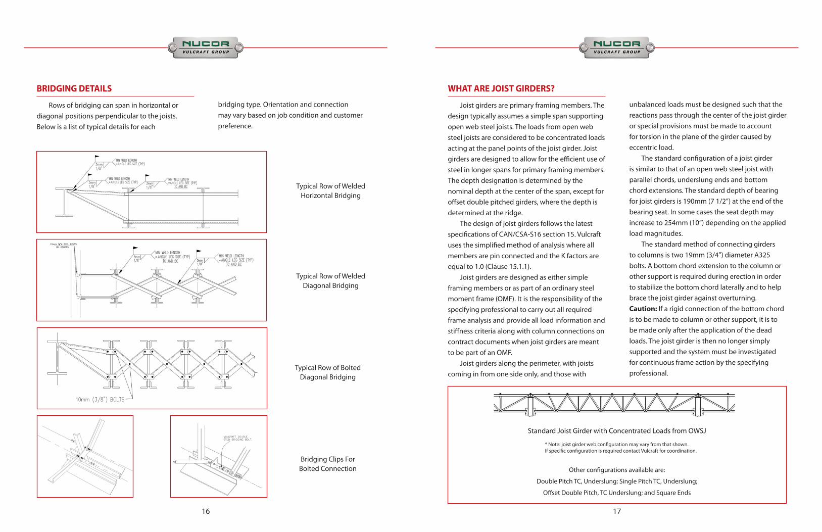
BRIDGING DETAILS
Rows of bridging can span in horizontal or diagonal positions perpendicular to the joists. Below is a list of typical details for each
bridging type. Orientation and connection may vary based on job condition and customer preference.
Typical Row of Welded Horizontal Bridging
Typical Row of Welded Diagonal Bridging
Typical Row of Bolted Diagonal Bridging
Bridging Clips For Bolted Connection
WHAT ARE JOIST GIRDERS?
Joist girders are primary framing members. The design typically assumes a simple span supporting open web steel joists. The loads from open web steel joists are considered to be concentrated loads acting at the panel points of the joist girder. Joist girders are designed to allow for the efficient use of steel in longer spans for primary framing members. The depth designation is determined by the nominal depth at the center of the span, except for offset double pitched girders, where the depth is determined at the ridge. The design of joist girders follows the latest specifications of CAN/CSA-S16 section 15. Vulcraft uses the simplified method of analysis where all members are pin connected and the K factors are equal to 1.0 (Clause 15.1.1). Joist girders are designed as either simple framing members or as part of an ordinary steel moment frame (OMF). It is the responsibility of the specifying professional to carry out all required frame analysis and provide all load information and stiffness criteria along with column connections on contract documents when joist girders are meant to be part of an OMF. Joist girders along the perimeter, with joists coming in from one side only, and those with
unbalanced loads must be designed such that the reactions pass through the center of the joist girder or special provisions must be made to account for torsion in the plane of the girder caused by eccentric load. The standard configuration of a joist girder is similar to that of an open web steel joist with parallel chords, underslung ends and bottom chord extensions. The standard depth of bearing for joist girders is 190mm (7 1/2”) at the end of the bearing seat. In some cases the seat depth may increase to 254mm (10”) depending on the applied load magnitudes. The standard method of connecting girders to columns is two 19mm (3/4”) diameter A325 bolts. A bottom chord extension to the column or other support is required during erection in order to stabilize the bottom chord laterally and to help brace the joist girder against overturning. Caution: If a rigid connection of the bottom chord is to be made to column or other support, it is to be made only after the application of the dead loads. The joist girder is then no longer simply supported and the system must be investigated for continuous frame action by the specifying professional.
Standard Joist Girder with Concentrated Loads from OWSJ
* Note: joist girder web configuration may vary from that shown. If specific configuration is required contact Vulcraft for coordination.
Other configurations available are:
Double Pitch TC, Underslung; Single Pitch TC, Underslung;
Offset Double Pitch, TC Underslung; and Square Ends

1918
JOIST GIRDER NOTES
(a) All joist girder dimensions shown are subject to change when required by the physical size of large joist girders. If changes are necessary Vulcraft will so note on the placement plans. (b) The standard connection for joist girders to columns is 22mm (7/8 inch) holes for 19mm (3/4 inch) diameter bolts in girder bearings. The girder erection bolts are not supplied by Vulcraft. If the specifying professional wishes to use the joist girder bearing to transmit horizontal loads, the required amount of weld to connect the joist girder seat to the column should be specified in order to size girder seats accordingly. For additional information see the section of this catalog, JOIST GIRDERS IN LATERAL LOAD RESISTANT FRAMES. (c) Stabilizer plates between the bottom chord angles brace the joist girder against overturning during erection and also provide needed lateral
bracing for load cases where the bottom chord may be subject to compression such as net uplift. (d) Joist girder bottom chord struts do not require welding to the stabilizer plate unless required by design to transmit horizontal forces. When welding is required, the amount of weld should be specified by the specifying professional. Unless otherwise specified, bottom chord struts should not be welded. (e) Joists are connected to the girder by welding except that the joists at (or nearest) the column shall also be bolted. (f ) The l/ry of the bottom chord of the joist girder cannot exceed 240. For standard joist girders, the Vulcraft engineer will use that criteria to determine the correct number of bottom chord braces once a joist layout is established. Joist girders which must resist uplift, end moments, or axial bottom chord forces may require additional braces.
GIRDER
GIRDER BOLTEDTO COLUMN (b)
JOIST BOLTED (e)TO GIRDER
TYPICAL SECTION @ WIDE FLANGE COLUMN FLANGE
TYPICAL SECTION @ WIDE FLANGE COLUMN FLANGE(Square columns similar)
TYPICAL GIRDER SECTION @ WIDE FLANGE COLUMN WEBTYPICAL FLOOR GIRDER @ WIDE FLANGE COLUMN FLANGE
GIRDER BOTTOM CHORD BRACE
Stabilizer Plate (c)
Clip angle seat forjoist at col. line
19mm (3/4”) Stabilizer Plate (c)
(d)
(e) (e)
Hold each joist back 6mm (1/4”) from CL of joist girder
Bottom Chord Brace(Welded Connection)
Welded Connection
JOIST GIRDER
(f )
Extend end 50mm (2”) past centerline of joist girder50mm
2”
JOIST GIRDER
JOIST BEARING ON ONESIDE ONLY OF GIRDER
(incl. Perimeter Girders)
ECONOMY TIPS
1. If joist girder depth is limited below the optimum depth as shown in calculations, use the maximum depth permitted by the building system. Odd depths (i.e. 53”, 41”) can be designed and furnished. 2. Joist girder designations are required on contract drawings to avoid any extra coordination. The specifying professional is required to specify the exact depth, span and loading that best suits the building. (Ex. 1500G8N50/35kN, where 1500 is the depth in mm, G is to identify mark as a girder, 8N is
number of joist spaces and 50/35 are the Total/Live load end reactionsof the seven joists along the span.) 3. Vulcraft recommends a joist girder depth to span ratio between 1:12 and 1:16 as a good range for economy. 4. The specifying professional is urged to investigate several combinations of bay sizes and joist spaces to find the most economical combination. 5. The following tables illustrates the economy possible using this system.
If end moments or uplift are present, bottom chord braces will be supplied by the joist girder manufacturer. If any additional braces are required due to the compression loads in the bottom
chord, Vulcraft will indicate their location on the placement plans. Bottom chord braces may be either welded or bolted to the girder, but are typically welded to the joist.
Note: Roof System Weight Tables shown above do not include weight of deck or bridging. Add 0.03 kPa (0.5 psf ) to account for bridging.
The larger bay sizes become more economical as the column heights increase and in localities with high erection labor costs. Larger bays speed construction by reducing the number of pieces and therefore the number of crane lifts. Encasing the columns for fire proofing or decoration also makes the larger bays more attractive.
In order to provide a quicker turnaround with Vulcraft joist girders, Vulcraft encourages the design professional to define the joist girders’ required depth, and equally spaced reactions in kN or kips from simply supported joists. If joist girder holds non-uniformly spaced joist and varying reactions along it’s span then the joist spacing and reaction magnitude must be defined on the contract documents.
2120
JOIST GIRDER IN LATERALLOAD RESISTANT FRAMES
When a joist girder is used as a component of a moment resistive frame, both the design wind/seismic moment and any continuity (usually live load) moment must be specified for each end of each affected joist girder. Provided this information, Vulcraft will design the joist girder as a simply supported truss for full gravity loading. The “fixed end” moments are then applied to the joist girder. Using the appropriate combinations of the gravity loads, the wind/seismic moments, and/or the continuity moments, the critical member stresses are identified and the joist girder members are sized accordingly. Vulcraft does not design the joist girder for any dead load moments unless specifically instructed to do so on the structural drawings. For this reason it is very important that on the structural drawings the specifying professional specify that all dead loads be applied to the joist girders before the bottom chord struts are welded to the stabilizer plates. Vulcraft has done extensive testing of the maximum eccentric top chord force capacity for joist girders. Based on this test program, the maximum horizontal load for 190mm (7.5”) deep seats are presented in Table 1 (below)
If the axial load due only to the wind/seismic moment does not exceed the values in Table 1, a
strap angle connecting the joist girders together as shown in Figure 2 can be used to resist the continuity moments. By tying the joist girder ends together, the joist girder-to-cap plate connection need only resist the wind/seismic loads, the strap angles do not transfer wind/seismic moments to the column. The design of such a strap angle to resist the continuity moments is the responsibility of the specifying professional. When the end moments on the joist girders are too large for the seat to resist, it is necessary to utilize a moment plate as shown in Details A-F (next page). The use of this simple moment plate virtually eliminates all eccentricity problems. Minimum joist girder top chord widths can be obtained from approval calculations. If they are required sooner contact your Vulcraft sales representative. Once the joist girder top chord width is known, the specifying professional can easily size the moment plate and its weld requirements to complete the connection detail.
Table 1.These values are based on using 19mm (3/4 “) A325 bolts and minimum of two 6mm (1/4”) fillet welds 127 mm (5 “) long along the sides of the seat. Vulcraft must be notified of seat forces for seat design.
Figure 1.
Figure 2.
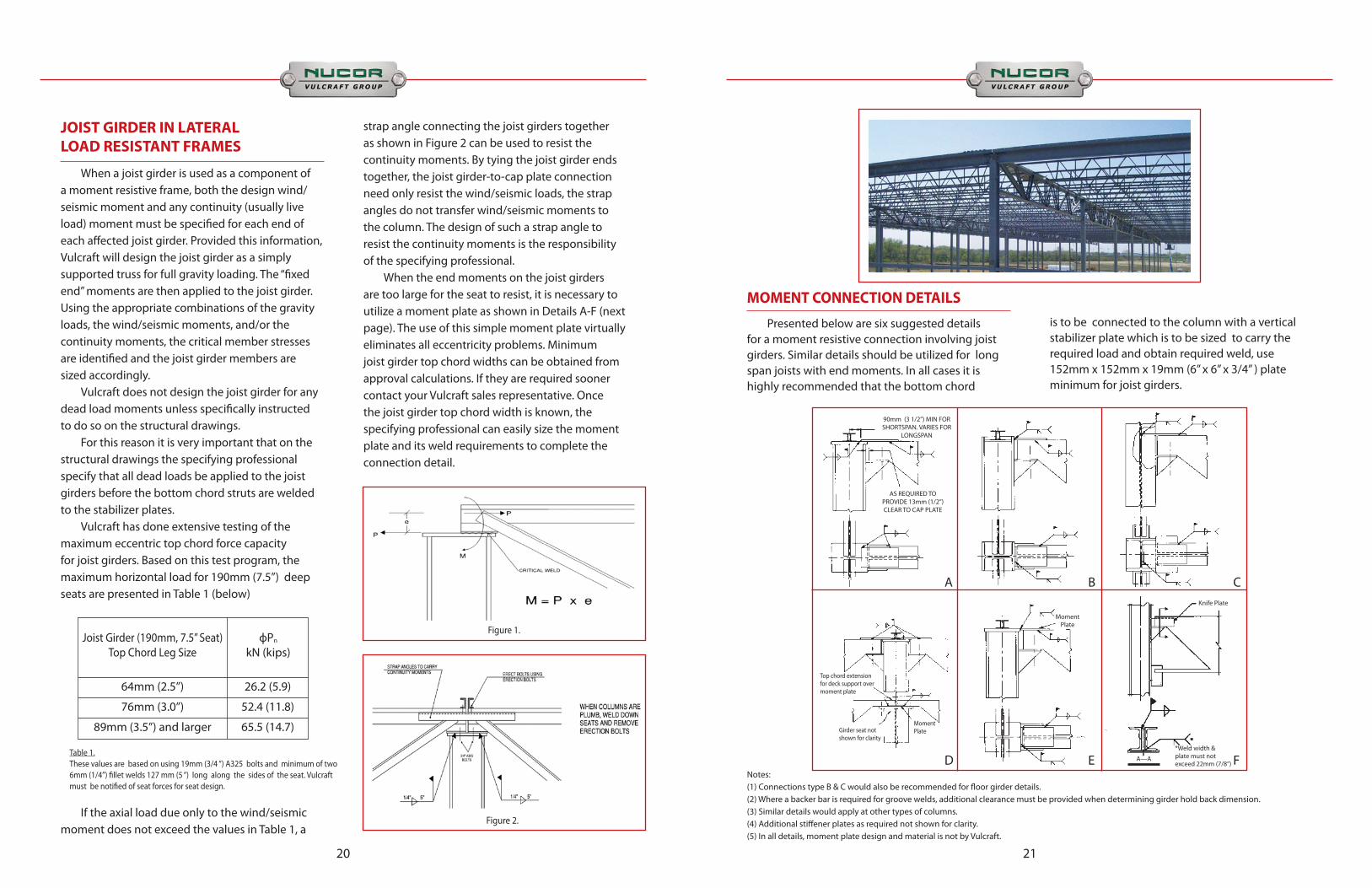
MOMENT CONNECTION DETAILS
Presented below are six suggested details for a moment resistive connection involving joist girders. Similar details should be utilized for long span joists with end moments. In all cases it is highly recommended that the bottom chord
is to be connected to the column with a vertical stabilizer plate which is to be sized to carry the required load and obtain required weld, use 152mm x 152mm x 19mm (6” x 6” x 3/4” ) plate minimum for joist girders.
Notes:(1) Connections type B & C would also be recommended for floor girder details.(2) Where a backer bar is required for groove welds, additional clearance must be provided when determining girder hold back dimension. (3) Similar details would apply at other types of columns. (4) Additional stiffener plates as required not shown for clarity. (5) In all details, moment plate design and material is not by Vulcraft.
90mm (3 1/2”) MIN FOR SHORTSPAN. VARIES FOR
LONGSPAN
AS REQUIRED TO PROVIDE 13mm (1/2”) CLEAR TO CAP PLATE
A B C
D E F
MomentPlate
*Weld width & plate must notexceed 22mm (7/8”)
Knife Plate
A—A
Top chord extensionfor deck support over moment plate
Girder seat notshown for clarity
Moment Plate
2322
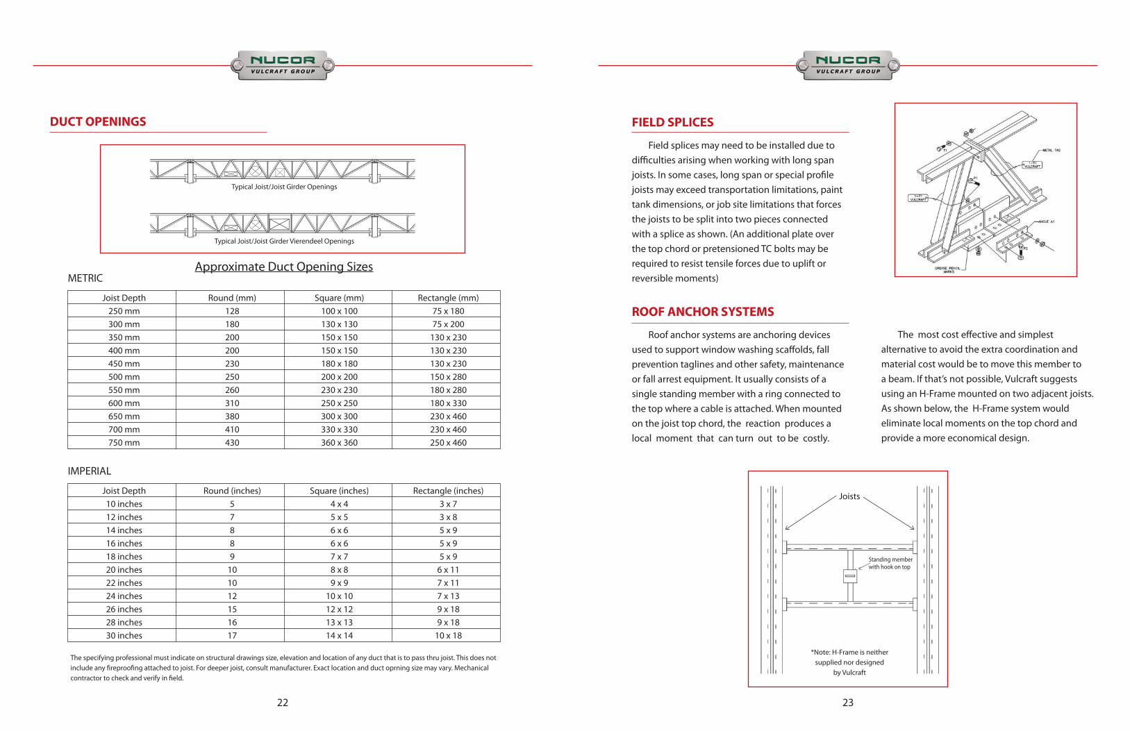
DUCT OPENINGS
Joist Depth Round (mm) Square (mm) Rectangle (mm) 250 mm 128 100 x 100 75 x 180 300 mm 180 130 x 130 75 x 200 350 mm 200 150 x 150 130 x 230 400 mm 200 150 x 150 130 x 230 450 mm 230 180 x 180 130 x 230 500 mm 250 200 x 200 150 x 280 550 mm 260 230 x 230 180 x 280 600 mm 310 250 x 250 180 x 330 650 mm 380 300 x 300 230 x 460 700 mm 410 330 x 330 230 x 460 750 mm 430 360 x 360 250 x 460
METRIC
Joist Depth Round (inches) Square (inches) Rectangle (inches) 10 inches 5 4 x 4 3 x 7 12 inches 7 5 x 5 3 x 8 14 inches 8 6 x 6 5 x 9 16 inches 8 6 x 6 5 x 9 18 inches 9 7 x 7 5 x 9 20 inches 10 8 x 8 6 x 11 22 inches 10 9 x 9 7 x 11 24 inches 12 10 x 10 7 x 13 26 inches 15 12 x 12 9 x 18 28 inches 16 13 x 13 9 x 18 30 inches 17 14 x 14 10 x 18
IMPERIAL
Approximate Duct Opening Sizes
The specifying professional must indicate on structural drawings size, elevation and location of any duct that is to pass thru joist. This does not include any fireproofing attached to joist. For deeper joist, consult manufacturer. Exact location and duct oprning size may vary. Mechanical contractor to check and verify in field.
Typical Joist/Joist Girder Openings
Typical Joist/Joist Girder Vierendeel Openings
FIELD SPLICES
Field splices may need to be installed due to difficulties arising when working with long span joists. In some cases, long span or special profile joists may exceed transportation limitations, paint tank dimensions, or job site limitations that forces the joists to be split into two pieces connected with a splice as shown. (An additional plate over the top chord or pretensioned TC bolts may be required to resist tensile forces due to uplift or reversible moments)
ROOF ANCHOR SYSTEMS
Roof anchor systems are anchoring devices used to support window washing scaffolds, fall prevention taglines and other safety, maintenance or fall arrest equipment. It usually consists of a single standing member with a ring connected to the top where a cable is attached. When mounted on the joist top chord, the reaction produces a local moment that can turn out to be costly.
The most cost effective and simplest alternative to avoid the extra coordination and material cost would be to move this member to a beam. If that’s not possible, Vulcraft suggests using an H-Frame mounted on two adjacent joists. As shown below, the H-Frame system would eliminate local moments on the top chord and provide a more economical design.
Joists
Standing memberwith hook on top
*Note: H-Frame is neithersupplied nor designed
by Vulcraft

2524
FLOOR VIBRATION
Floor vibration occurs, in varying degrees, in all types of building construction. Unlike steady state vibration, which can be isolated, vibration due to human impact is inconsistent in amplitude and frequency and, therefore, more difficult to control. The Steel Joist Institute and Nucor Research and Development have studied this phenomenon for many years. Laboratory research has been performed and numerous buildings, exhibiting both good and bad characteristics, were tested using seismic recording instruments. AISC / CISC Steel Design Guide 11 (1997) discusses in detail methods for calculating vibrational properties for joist supported floors. The vast majority of structures, including those utilizing steel joists, do not exhibit floor vibrations severe enough to be considered objectionable. However, human sensitivity to vibratory motion varies, and a satisfactory framing solution is dependent upon the sound judgment of qualified structural engineers. Analysis should be performed prior to bidding by the design professional considering the joists as part of the total building system. Vulcraft recommends specifying a minimum moment of inertia for joists as a way to meet the vibration criteria of the structure. Floor vibration is measured in terms of acceleration amplitude, displacement amplitude, and frequency. These factors are not objectionable to all people at the same level since human sensitivity varies. Acceleration amplitude is the maximum acceleration caused by a force excitation. Displacement amplitude is the magnitude or total distance traveled by each oscillation of the vibration. Frequency is the speed of the oscillations and is expressed in cycles per second or Hz. Acceleration is the only vibration factor which humans can sense. Damping is the rate of decay of amplitude. The following observations, which were determined from research data to be beneficial in reducing vibration levels, are recommended only as a guide. Open floor areas are most subject to vibrational problems. Modern “electronic offices” tend to have
lower live loading and damping, and hence can potentially be more prone to floor vibration. Partitions, file cabinets, book stacks, heavy furnishings and even crowds of people provide additional damping and minimize complaints. Thicker floor slabs are an economical solution to floor vibration. Additional thickness increases floor system stiffness transverse to the joists, thus reducing the vibration. The additional mass of the system will reduce the objectionable vibration. Wider joist spacings improve vibrational characteristics only when combined with thicker floor slabs. The resulting increase in joist size does not contribute significantly to the composite section. When used with a thicker slab, greater resistance to vibration can be achieved, and, since fewer pieces must be installed, may be more economical. Partitions introduce damping and usually eliminate vibration problems. They will be effective either above or below a floor as long as they are connected to the floor. Partitions below a joist supported floor ideally should be in direct contact with the steel deck. If partitions below a joist supported floor are in direct contact with the joists, the joist bottom chord and webs must be designed for such intermediate support conditions. Consideration should be given to potential changes in occupancy of a floor over the expected life expectancy of the building. Going from a paper office to an electronic office along with removal of partitions can cause unexpected vibration problems. Support framing beams sometimes contribute to floor vibration. The natural frequency and amplitude for both the joist and supporting joist girders or hot-rolled girders need to be calculated. In this manner the resulting system acceleration or displacement and frequency can be determined from which the performance of the system can be predicted. Increasing joist stiffness above that which is required by live load deflection may be beneficial. A higher frequency floor is generally a better floor for most applications. Increasing the stiffness of the steel joists results in increasing the frequency and slightly decreasing the acceleration or displacement of the floor vibration.
Longer floor spans have many advantages over shorter spans, both in construction cost and in vibrational response. Floor spans over 12m (40’) with a 64mm (2-1/2”)thick concrete slab give a vibrational frequency in the 3 - 5 cycles per second range. There are many long spanning joist supported floors that perform satisfactorily. A careful evaluation should be made by the specifying professional determining predicted floor vibration properties.
PC-based software to evaluate vibration of joist supported floor systems is available from:
Structural Engineers, Inc. and Steel Joist Institute537 Wisteria Dr. 234 W. Cheves St.Radford, VA 24141 Florence, SC 29501Tel : (540) 731-3330 Tel : (843) 407-4091
PRIMER COATING AND SURFACE PREPARATION
Standard Primer The standard primer for Vulcraft Open Web Steel Joist products, unless otherwise specified, is a shop-coat of rust inhibitive primer which meets or exceeds the functional requirements of CISC/CPMA 1-73a. The method of application is by dipping the joist in a tank of grey primer or rolling the joist through a flow coating device. Vulcraft uses near blue steel from Nucor mills requiring no surface preparation to achieve the specified performance requirements. CISC/CPMA 1-73a calls for a quick-drying one-coat primer for use on structural steel that provides adequate protection against exposure to non-corrosive environment as found in rural, urban, or semi-industrial settings for a period not exceeding six months. This primer is intended for use on structural steel which, with the exception of a short period of time during construction, will function in interior exposures of a normally dry nature prior to application of top finish coat. Vulcraft’s standard primer color for CISC/CPMA 1-73a and 2-75 is grey and the standard minimum dry film thickness (DFT) provided is 37 micrometers (1.5
mils). Vulcraft can provide a specific minimum DFT at an additional cost if indicated in the specifications or contract drawings. Vulcraft products receive the same primer which is formulated to meet the requirements and performance specifications of both CISC/CPMA 1-73a and CISC/CPMA 2-75. However, CISC/CPMA 2-75 requires additional surface preparation and other application requirements which can be provided with coordination and additional costs.
Special Primer and surface protection: Vulcraft can offer special surface protection requirements, at an additional cost, including CISC/CPMA 2-75 primer with surface preparation following SSPC SP6 and SP7, special epoxy coatings or galvanization as per project specifications. The standard shop primer of CISC/CPMA 1-73a or 2-75 is not recommended where a high performance, anti-corrosive surface protection is required in exposed or corrosive areas or where special environmental conditions like SSPC environmental zones 2A or above are anticipated. Special paints and coatings must be selected and specified to meet these requirements. Where food processing or extra clean atmospheres are required, the designer must consider specifying non-standard welding and special paints.

NOTES
2726
NOTES

VULCRAFT CANADA, INC.1362 Osprey Drive
Ancaster, ON L9G 4V5Tel: 289-443-2000Fax: 905-304-8846
Email: [email protected]
VULCRAFT OF NEW YORK, INC.621 Main Street
Chemung, New York 14825Tel: 607-529-6000Fax: 607-529-9001
Email: [email protected]
VULCRAFT OF UTAH1875 West Highway 13 South
P.O. Box 637Brigham City, Utah 84302
Tel: 435-734-9433Fax: 435-723-5423
Email: [email protected]
VULCRAFT OF INDIANA6610 County Road 60
P.O. Box 1000St. Joe, Indiana 46785
Tel: 260-337-1800Fax: 260-337-1801
Email: [email protected]
www.nucor.com www.vulcraft.ca
VULCRAFT PLANTS SERVING CANADA
Vulcraft/Verco production facilities in North America
2017 Canadian Joist Catalog.indd 8 11/28/16 2:10 PM


