64
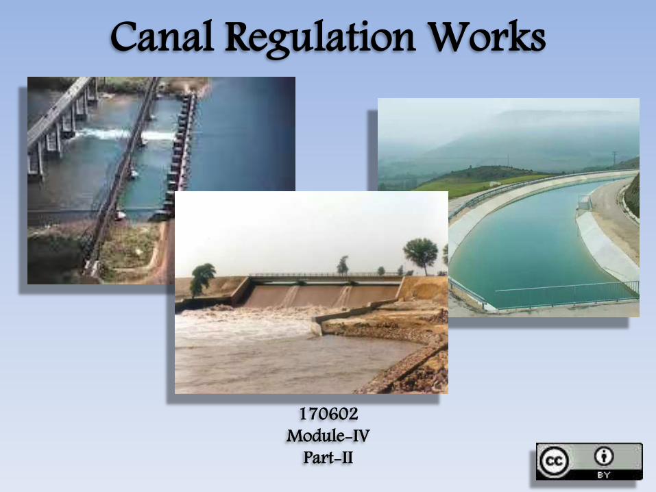
Canal Regulation Works 170602 Module-IV Part-II
| Date post: | 15-Jul-2015 |
| Category: |
Engineering |
| Upload: | gaurav-h-tandon |
| View: | 912 times |
| Download: | 20 times |
Canal Regulation Works
170602Module-IV
Part-II
Syllabus• Canal Regulation Works:• Canal Fall- Necessity and Location- Types of
Falls- Cross Regulator and Distributory HeadRegulator- Their Functions, Silt ControlDevices, Canal Escapes- Types of Escapes.
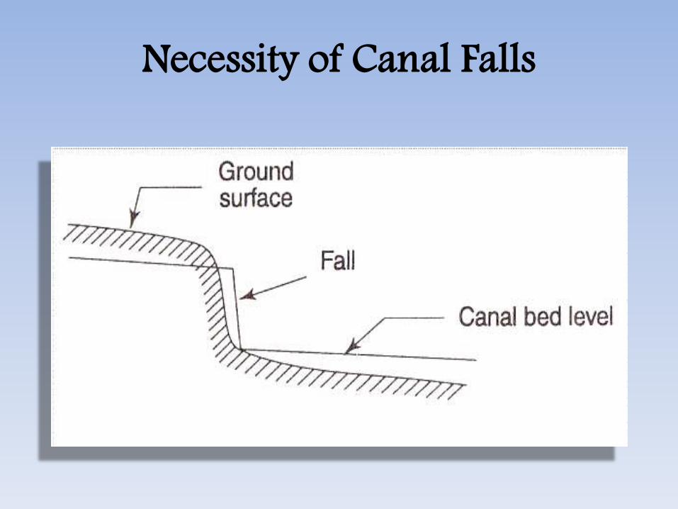
What is Canal Fall? • Whenever the available natural ground slope
is steep than the designed bed slope of thechannel, the difference is adjusted byconstructing vertical ‘falls’ or ‘drops’ in the canalbed at suitable intervals, as shown in figurebelow. Such a drop in a natural canal bed willnot be stable and, therefore, in order to retainthis drop, a masonry structure is constructed.Such a structure is called a Canal Fall or aCanal drop.

Canal Fall
Canal FallIrrigation canals are designed for a prescribed bedslope so that velocity becomes non silting or nonscouring. But if the ground topography is such that inorder to maintain the canal designed slope, indefinitefilling from falling ground level is to be made. Thisindefinite filling is avoided by constructing a hydraulicstructure in the place of sudden bed level. Thishydraulic structure is called canal fall or drop. Beyondthe canal fall, canal again maintains its designed slope.

Canal Fall• Thus, a canal fall or drop is an irrigation structure
constructed across a canal to lower down its bedlevel to maintain the designed slope when there is achange of ground level to maintain the designedslope when there is change of ground level. Thisfalling water at the fall has some surplus energy. Thefall is constructed in such a way that it can destroythis surplus energy.
Necessity of Canal Falls• When the slope of the ground suddenly changes
to steeper slope, the permissible bed slope cannot be maintained. It requires excessiveearthwork in filling to maintain the slope. In sucha case falls are provided to avoid excessive earthwork in filling
Necessity of Canal Falls

Necessity of Canal Falls• When the slope of the ground is more or
less uniform and the slope is greater thanthe permissible bed slope of canal.
Necessity of Canal Falls• In cross-drainage works, when the difference
between bed level of canal and that ofdrainage is small or when the F.S.L of thecanal is above the bed level of drainagethen the canal fall is necessary to carry thecanal water below the stream or drainage.

Necessity of Canal Falls
Types of Canal Fall• Depending on the ground level conditions and shape
of the fall the various types of fall are:Ogee Fall• The ogee fall was constructed by Sir Proby Cautley on
the Ganga Canal. This type of fall has gradual convexand concave surfaces i.e. in the ogee form. The gradualconvex and concave surface is provided with an aimto provide smooth transition and to reducedisturbance and impact. A hydraulic jump is formedwhich dissipates a part of kinetic energy. Upstreamand downstream of the fall is provided by StonePitching.

Ogee Fall

Types of Canal FallStepped Fall• It consists of a series of vertical drops in the form of
steps. This steps is suitable in places where slopingground is very long and require a long glacis toconnect the higher bed level u/s with lower bed leveld/s. it is practically a modification of rapid fall. Thesloping glacis is divided into a number drops to bringdown the canal bed step by step to protect the canalbed and sides from damage by erosion. Brick walls areprovided at each drop. The bed of the canal within thefall is protected by rubble masonry with surfacefinishing by rich cement mortar.

Stepped Fall
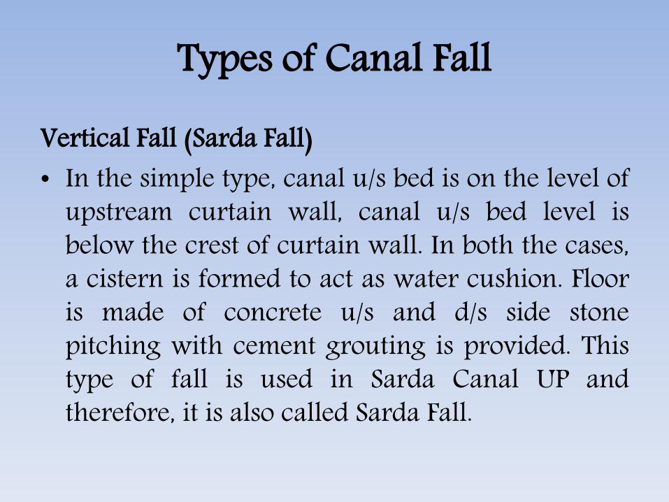
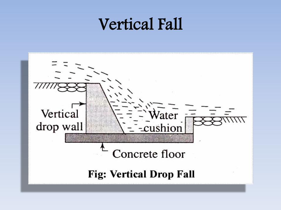
Types of Canal FallVertical Fall (Sarda Fall)• In the simple type, canal u/s bed is on the level of
upstream curtain wall, canal u/s bed level isbelow the crest of curtain wall. In both the cases,a cistern is formed to act as water cushion. Flooris made of concrete u/s and d/s side stonepitching with cement grouting is provided. Thistype of fall is used in Sarda Canal UP andtherefore, it is also called Sarda Fall.
Vertical Fall
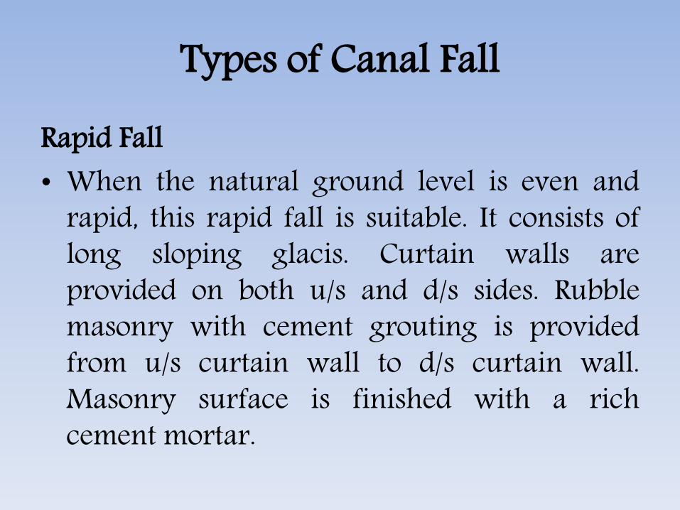
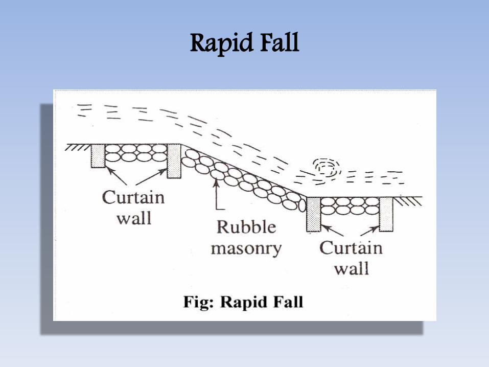
Types of Canal FallRapid Fall• When the natural ground level is even and
rapid, this rapid fall is suitable. It consists oflong sloping glacis. Curtain walls areprovided on both u/s and d/s sides. Rubblemasonry with cement grouting is providedfrom u/s curtain wall to d/s curtain wall.Masonry surface is finished with a richcement mortar.
Rapid Fall
Types of Canal FallStraight Glacis Fall• It consists of a straight glacis provided with a
crest wall. For dissipation of energy of flowingwater, a water cushion is provided. Curtainwalls are provided at toe and heel. Stonepitching is required at upstream anddownstream of the fall.

Straight Glacis Fall

Types of Canal FallTrapezoidal Notch Fall• It was designed by Reid in 1894. In this type a
body or foundation wall across the channelconsisting of several trapezoidal notches betweenside pier and intermediate pier is constructed.The sill of the notches are kept at upstream bedlevel of the canal. The body wall is made ofconcrete. An impervious floor is provided toresist the scouring effect of falling water.Upstream and downstream side of the fall isprotected by stone pitching finished with cementgrouting
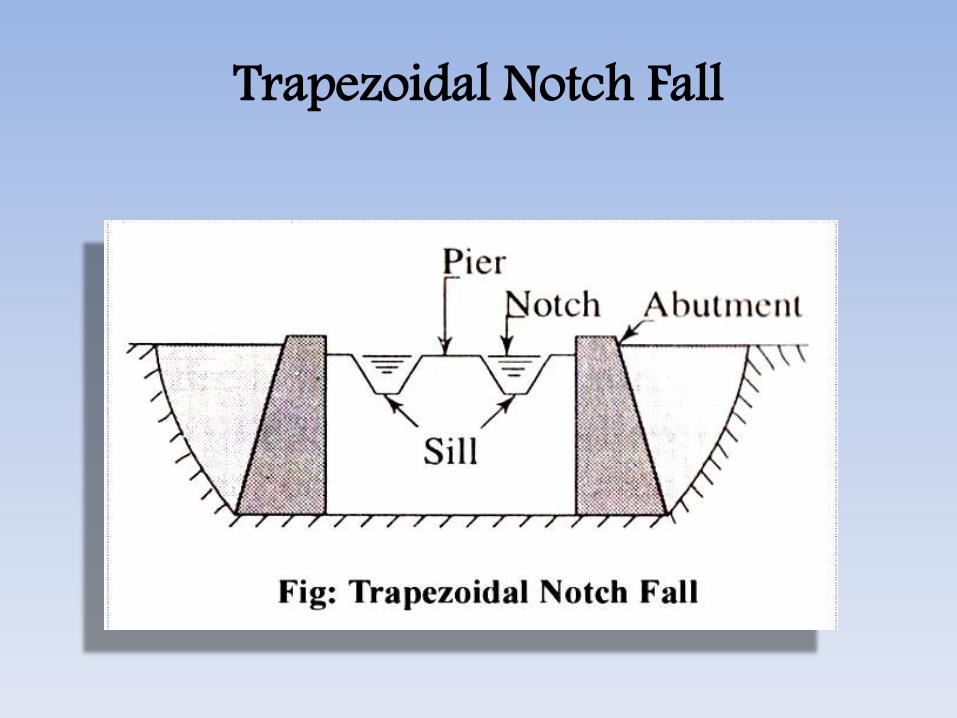
Trapezoidal Notch Fall
Types of Canal FallWell or Cylinder Notch Fall• In this type, water of canal from higher level
is thrown in a well or a cylinder from whereit escapes from bottom. Energy is dissipated inthe well in turbulence. They are suitable forlow discharges and are economical also.
Types of Canal FallMontague Type Fall• In the straight glacis type profile, energy
dissipation is not complete. Therefore,montague developed this type of profilewhere energy dissipation takes place. Hisprofile is parabolic and is given by thefollowing equation,

Montague Type Fall
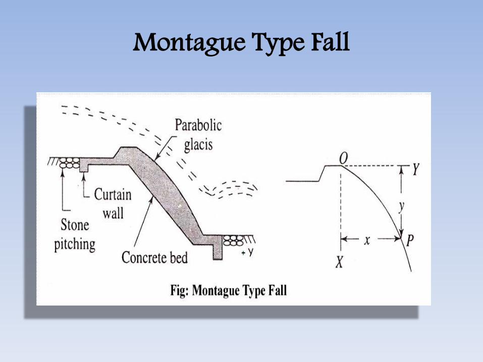
Montague Type Fall
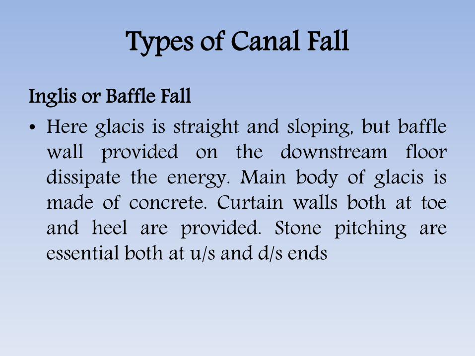
Types of Canal FallInglis or Baffle Fall• Here glacis is straight and sloping, but baffle
wall provided on the downstream floordissipate the energy. Main body of glacis ismade of concrete. Curtain walls both at toeand heel are provided. Stone pitching areessential both at u/s and d/s ends

Inglis or Baffle Fall
Canal Escape• It is a side channel constructed to remove
surplus water from an irrigation channel (maincanal, branch canal, or distributary etc.) into anatural drain.
• The water in the irrigation channel may becomesurplus due to -
• Mistake• Difficulty in regulation at the head• Excessive rainfall in the upper reaches• Outlets being closed by cultivators as they find
the demand of water is over
Canal Escape• It is the structure required to dispose of surplus or
excess water from canal from time to time. Thus, acanal escape serves as safety valve for canal system. Itprovides protection to the canal from possible damagedue to excess supply which may be due to mistake inreleasing water at head regulator or heavy rainfallthat makes sudden regular demand of water. Theexcess supply makes the canal banks vulnerable tofailure due to overtopping or dangerous leaks.Therefore, provision for disposing this surplus waterin form of canal escapes at suitable intervals along thecanal is essential. Moreover emptying canal for repairand maintenance and removal of sediment depositedin the canal can also be achieved with the help ofcanal escapes.

Escapes are usually of the following three types.
Surplus Escape• It is also called regulator type. In this type sill
of the escape is kept at canal bed level and theflow is controlled by a gate. This type ofescapes are preferred now-a-days as theygive better control and can be used foremploying the canal for maintenance.
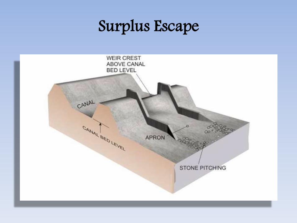
Surplus Escape
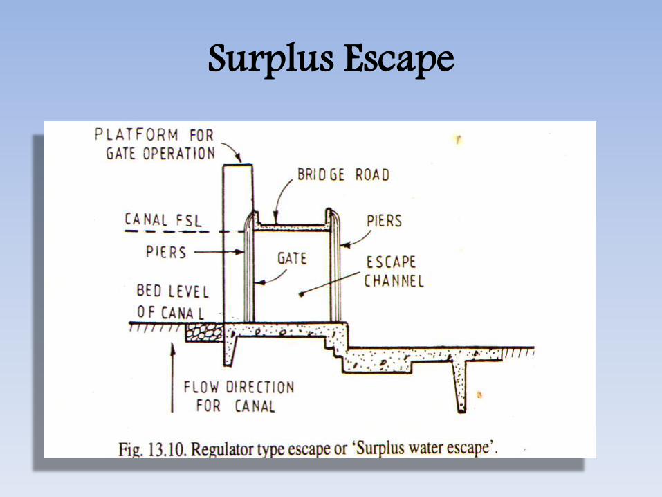
Surplus Escape

Escapes are usually of the following three types.
Tail Escape• A tail escape is provided at the tail end of the
canal and is useful in maintaining therequired FSL in the tail reaches of the canaland hence, they are called tail escape.
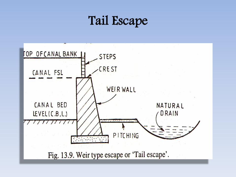
Tail Escape
Escapes are usually of the following three types.
Scouring Escape
• This escape is constructed for the purpose of scouringof excess silt deposited in the head reaches from timeto time. Hence, it is called scouring escape. Here thesill of the regulator is kept at about 0.3 m below thecanal bed level at escape site. When deposited silt to bescoured, a higher discharge than the FSL is allowed toenter the canal from the head works. The gate of theescape is raised so as to produce scouring velocitywhich remove the deposited silt. This type of Escapehas become obsolete as silt ejector provided in thecanal can produce better efficiency.
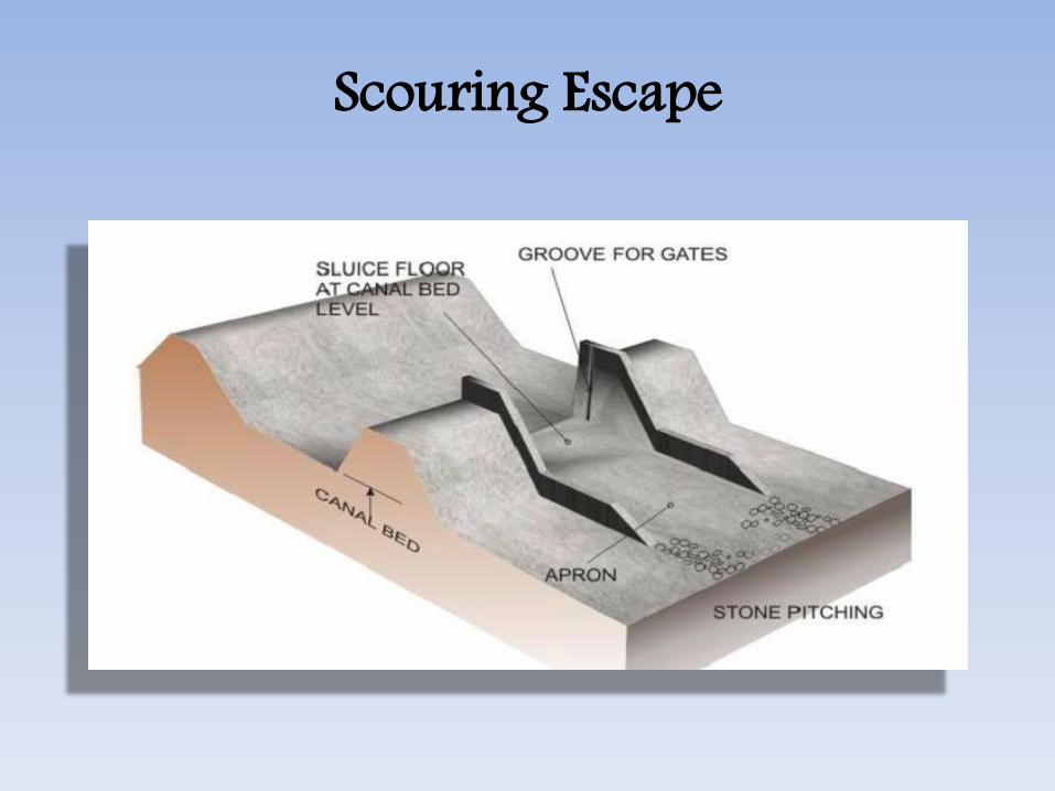
Scouring Escape
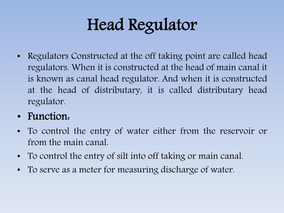
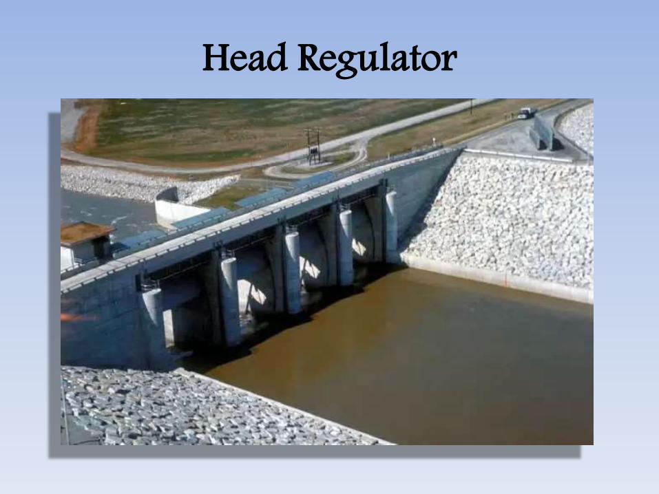
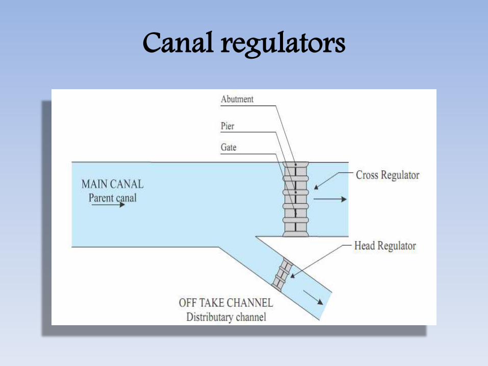
Head Regulator• Regulators Constructed at the off taking point are called head
regulators. When it is constructed at the head of main canal itis known as canal head regulator. And when it is constructedat the head of distributary, it is called distributary headregulator.
• Function:• To control the entry of water either from the reservoir or
from the main canal.• To control the entry of silt into off taking or main canal.• To serve as a meter for measuring discharge of water.

Head Regulator• Construction: The components of head regulator
depends upon the size of canal and location of headregulator. It consists of one or more gated researchopenings with barrels running through the bank.For large canals head regulators are flumed tofacilitate the measurement of discharge.
Head Regulator

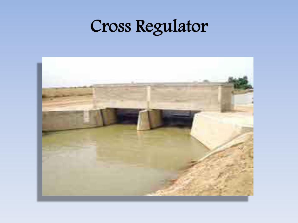
Cross Regulator• Cross Regulator• A Regulator Constructed in the main canal or parent
canal downstream of an off take canal is called cross-regulator.
• It is generally constructed at a distance of 9 to 12 kmalong the main canal and 6 to 10 km along branchcanal.
• Functions:• (i) To Control the flow of water in canal system• (ii) To feed the off taking Canals• (iii) To enable closing of the canal breaches on the d/s• (iv) To provide roadway for vehicular traffic
Cross Regulator
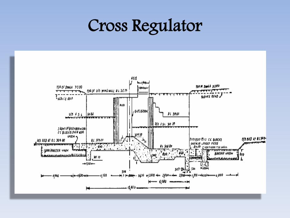
Cross RegulatorConstruction: For Cross Regulators abutmentswith grooves and piers are constructed parallelto the parent canal. The sill of regulation is keptlittle higher than the u/s bed level of canalacross which it is constructed. Vertical lift gatesare fitted in the grooves. The gates can beoperate from the road.

Canal regulators
Canal regulators
Cross Regulator

Head Regulator
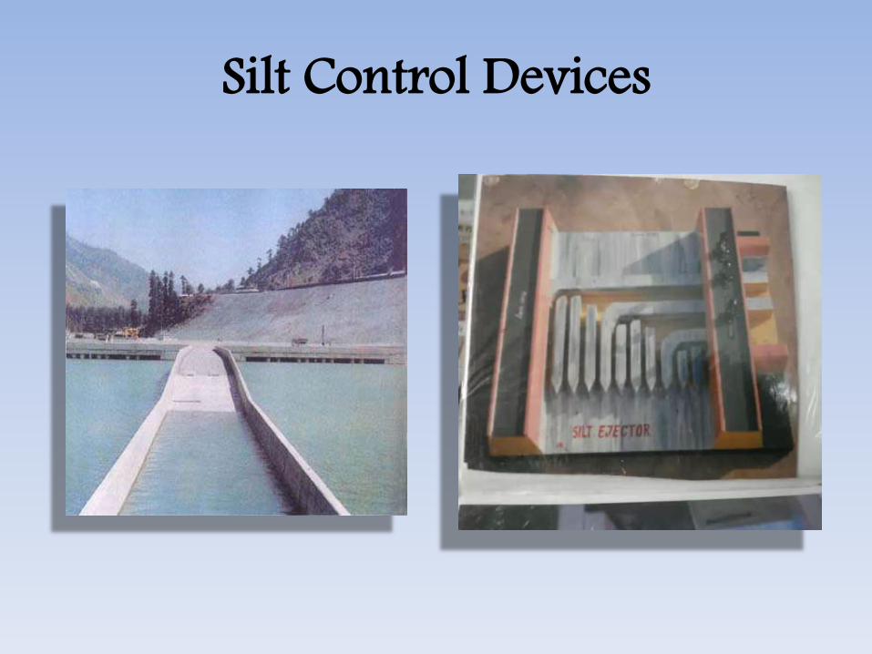
Silt Control Devices• Scouring Sluices or Under sluices, silt pocket and silt
excluders• The above three components are employed for silt
control at the head work. Divide wall creates a siltpocket. Silt excluder consists of a number undertunnels resting on the floor pocket. Top floor of thetunnel is at the level of sill of the head regulator.
• Various tunnels of different lengths are made. Thetunnel near the head regulator is of same length ofhead regulator and successive tunnels towards thedivide wall are short. Velocity near the silt laden wateris disposed downstream through tunnels and undersluices.

Silt Control Devices• Silt Excluder: The silt excluder is located on
the u/s of diversion weir and in front of thehead regulator. The object is to remove siltthat has entered in the stilling basin throughscouring sluices.
• Silt Ejector: Silt Ejector is located in the canaltake off from the diversion weir at 6 to 10 kmin the canal reach. It ejects the silt that hasentered in the canal

Silt Control Devices
Silt Excluder

Silt Control Devices
Silt Ejector
Silt Control Devices

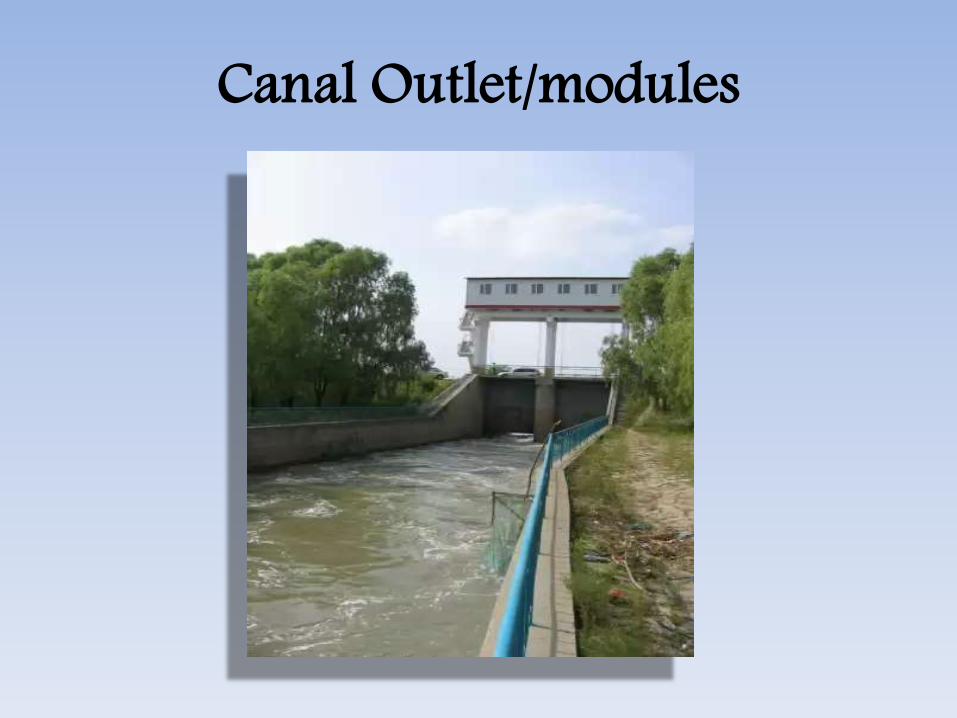
Canal Outlet/modules • A canal outlet or a module is a small
structure built at the head of the watercourse so as to connect it with a minor or adistributary channel.
• It acts as a connecting link between thesystem manager and the farmers.
Canal Outlet/modules
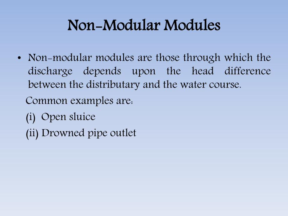
Non-Modular Modules
• Non-modular modules are those through which thedischarge depends upon the head differencebetween the distributary and the water course.Common examples are:(i) Open sluice(ii) Drowned pipe outlet

Types of Outlet/modules• Non-modular modules
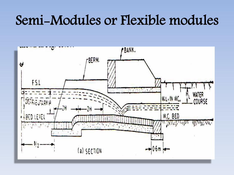
Semi-Modules or Flexible modules• Due to construction, a super-critical velocity is
ensured in the throat and thereby allowing theformation of a jump in the expanding flume.
• The formation of hydraulic jump makes the outletdischarge independent of the water level in watercourse, thus making it a semi module. Semi-modulesor flexible modules are those through which thedischarge is independent of the water level of thewater course but depends only upon the water level ofthe distributary so long as a minimum working head isavailable.
• Examples are pipe outlet, open flume type etc.
Semi-Modules or Flexible modules
Rigid Modules or Modular Outlets• Rigid modules or modular outlets are those through
which discharge is constant and fixed within limits,irrespective of the fluctuations of the water levels ofeither the distributary or of the water course or both.
• An example is Gibb’s module:
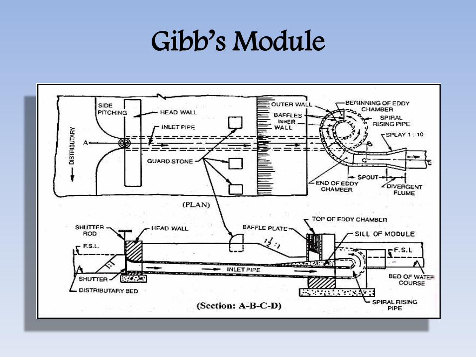
Gibb’s Module
Exam Questions Dec 2011, June 2012
• What do you understand by a fall incanal? Why it is necessary?
• What are the functions of a canal headregulator?
• Explain functions of cross regulator anddistributory head regulator.
• Write a S.N. on Types of Canal Falls

References• Irrigation Engineering
– By Prof N N Basak– Tata Mcgraw-Hill
• Irrigation Engineering & Hydraulic Structures– By Prof. Santosh Kumar Garg– Khanna Publishers
• Internet Websites• http://www.uap-bd.edu/• Lecture Notes By: Dr. M. R. Kabir • Professor and Head, Department of Civil Engineering Department • University of Asia Pacific (UAP), Dhaka

Thanks………..GHT


