June 1983 NASA : TP ' 2157 I c.1 I I Canard-Controlled Missile at -Supersonic Mach Numbers A. B. Blair, Jr., Jerry M. Allen, and Gloria Hernandez LOAN COPY: RETURN TO AFWL TECHT-4ICAL LIBRARY K!RTLAND ,433, N.M. 87117 25th Anniversary 1958-1983
Transcript
June 1983
NASA : TP ' 2157 I c.1 I I
Canard-Controlled Missile at -Supersonic Mach Numbers
A. B. Blair, Jr., Jerry M. Allen, and Gloria Hernandez
Effect of Tail-Fin Span on Stability and Control Characteristics of a Canard-Controlled Missile at Supersonic Mach Numbers
A. B. Blair, Jr., Jerry M. Allen, and Gloria Hernandez Langley Research Center Hampton, Virginia
I
SUMMARY
A n experimental wind-tunnel invest igat ion has been conducted a t Mach numbers from 1.60 t o 3.50 to ob ta in t he l ong i tud ina l and l a t e ra l -d i r ec t iona l ae rodynamic c h a r a c t e r i s t i c s of a c i r cu la r , c ruc i fo rm, cana rd -con t ro l l ed missile w i t h v a r i a t i o n s i n t a i l - f i n s p a n . I n a d d i t i o n , c o m p a r i s o n s were made wi th the exper imenta l aero- dynamic c h a r a c t e r i s t i c s u s i n g t h r e e missile aeropredict ion programs: MISSILEl, MISSILE2, and NSWCDM. The r e s u l t s o f t h e i n v e s t i g a t i o n i n d i c a t e t h a t f o r t h e test Mach number range, canard roll c o n t r o l a t low a n g l e s o f a t t a c k is f e a s i b l e on t a i l - f in con f igu ra t ions w i th t a i l - t o -cana rd span ratios of less than or equa l t o 0.75. The canards are e f f e c t i v e p i t c h and yaw con t ro l dev ices on each ta i l - f in span config- u r a t i o n t e s t e d . Programs MISSILE1 and MISSILE2 provide very good p r e d i c t i o n s of long i tud ina l ae rodynamic cha rac t e r i s t i c s and f a i r p red ic t ions o f l a t e ra l -d i r ec t iona l aerodynamic charac te r i s t ics a t low ang les o f a t t ack , w i th MISSILE2 p r e d i c t i o n s gen- e r a l l y i n b e t t e r a g r e e m e n t w i t h tes t da t a . Program NSWCDM provides good l o n g i t u d i n a l and la te ra l -d i rec t iona l aerodynamic p red ic t ions tha t improve wi th increases in t a i l - f i n span. Estimates of roll ing-moment coefficient are i n good agreement with t e s t d a t a a t l o w ang le s of a t t a c k . Programs MISSILEl, MISSILE2, and NSWCDM a p p e a r t o be acceptab le engineer ing des ign tools f o r a e r o p r e d i c t i o n a n d , i n g e n e r a l , make rea- sonab le e s t ima tes of t h e t es t da t a ; however, these programs need t o be modified i n o r d e r t o bet ter p r e d i c t t h e l a t e r a l - d i r e c t i o n a l a e r o d y n a m i c c h a r a c t e r i s t i c s a t h ighe r ang le s of a t tack (grea te r than 12O) .
INTRODUCTION
It is w e l l documented t h a t missile conf igu ra t ions u t i l i z ing fo rward -con t ro l surfaces experience the problem of induced rol l ing moments a t s u p e r s o n i c Mach num- bers. (See r e f s . 1 t o 3. ) For these forward-control led configurat ions, the need i s e i t h e r t o r e d u c e o r e l i m i n a t e t h e i n d u c e d r o l l i n g moments o r t o p r o v i d e a n e f f i c i e n t sys t em fo r t he i r con t ro l .
A p r e l i m i n a r y a n a l y t i c a l s t u d y ( r e f . 4 ) f o r a class of canard-controlled-missile conf igu ra t ions s imi l a r t o t he S idewinde r missile has indicated that aerodynamic improvements can be made with the implementation of a canard ro l l -cont ro l sys tem. Such a system requires a r e d u c t i o n i n t a i l - f i n s p a n a n d e l i m i n a t e s t h e need f o r r o l l - erons which are cur ren t ly be ing used to p roduce airframe damping i n ro l l . In an e f f o r t to complement and v e r i f y t h e p r e d i c t i o n s f r o m t h i s s t u d y , a coopera t ive NASA/ Motorola missile research program w a s e s t a b l i s h e d .
This jo in t research program cons is ted of a parametr ic supersonic wind-tunnel i nves t iga t ion o f a canard-cont ro l led missile w i t h s y s t e m a t i c v a r i a t i o n s i n t a i l - f i n span for the purpose o f es tab l i sh ing a comprehensive experimental aerodynamic data base. The p r e s e n t p a p e r p r e s e n t s t h e r e s u l t s of t h a t i n v e s t i g a t i o n . A summary of t he s ign i f i can t f i nd ings , a long w i th l imi t ed compar i sons of experimental and ana- l y t i c a l aerodynamic charac te r i s t ics , has been repor ted in re fe rences 5 t o 7. The p resen t s tudy i nc ludes t a i l - f in span op t imiza t ions for s t a b i l i t y , l o n g i t u d i n a l a n d d i r ec t iona l con t ro l , i nduced ro l l and r o l l con t ro l , and t he e f f ec t s o f missile roll o r i e n t a t i o n . I n a d d i t i o n , t h r e e missile aerodynamic predict ion programs are eval- ua ted by comparison with the test da ta . The prediction programs are d e s c r i b e d i n d e t a i l i n r e f e r e n c e s 8 to 12 and include MISSILEl, MISSILE2, and NSWCDM.
The t e s t s were conducted i n the Langley Unitary Plan Wind Tunnel a t Mach numbers from 1.60 t o 3.50 f o r a Reynolds number of 6.6 X 10 per meter ( 2 . 0 x l o 6 p e r f o o t ) . The nominal angle-of-attack range was from - 4 O t o 18' a t model r o l l a n g l e s of Oo , 26.6O, and 45'.
6
SYMBOLS
The aerodynamic coef f ic ien t da ta a re re fe r red to the body-axis system which i s f i x e d i n t he ve r t i ca l -ho r i zon ta l p l anes r ega rd le s s of the model r o l l a n g l e . The moment re ference cen ter i s l o c a t e d a f t of the model nose a t 45.0 percent of the body length .
Values are given i n both S I and U.S. Customary U n i t s . The measurements and c a l c u l a t i o n s were made i n U.S. Customary Uni t s . Fac to r s r e l a t ing t he two systems are given
A
AR
cA
'A,c
C~~
C~~
C I6
'm
% CN
C~~
'n
6
d
2
i n r e f e rence 13.
reference area (based on body diameter) I 14.081313 c m 2 (2.182608 i n 2 )
a s p e c t r a t i o of aerodynamic surface based on t o t a l exposed planform area
r a t i o of exposed t a i l span to exposed canard span (body excluded)
ax ia l - force coef f ic ien t , Axia l force /qA
chamber a x i a l - f o r c e c o e f f i c i e n t , Chamber axial force/qA
c o e f f i c i e n t of canard root bending moment, Canard root bending moment/qAd ( see f i g . 18 )
c o e f f i c i e n t of canard hinge moment, Canard hinge moment/qAd ( s e e f i g . 1 8 )
rol l ing-moment coeff ic ient , Rol l ing moment/qAd
r o l l - c o n t r o l e f f e c t i v e n e s s of two c a n a r d s a t a = Oo, Acl /Asro l l , per degree of d e f l e c t i o n
pitching-moment c o e f f i c i e n t , P i t c h i n g moment/qAd
p i t c h - c o n t r o l e f f e c t i v e n e s s of two c a n a r d s a t a = Oo, ACm/A6pitch' per degree of d e f l e c t i o n
normal-force coeff ic ient , Normal force/qA
c o e f f i c i e n t of canard normal force, Canard normal force/qA (see f ig. 1 8 )
yawing-moment c o e f f i c i e n t , Yawing moment/qAd
yaw-control effect iveness of two canards a t a = Oo, ACn/hGyawI per degree of d e f l e c t i o n
s ide- force coef f ic ien t , S ide force /qA
re fe rence body diameter, 4.234 cm (1.667 i n . )
1
M
q
x /I ac
a
'i
'pitch
' r o l l
'yaw
+
model length, 102.319 c m (40.283 in.)
f ree-s trearn Mach number
f ree-s t ream dynamic p r e s s u r e
aerodynamic-center location as f r a c t i o n of model length, measured from nose apex
angle of a t t ack , deg
a n g u l a r c o n t r o l d e f l e c t i o n of canard panel where subscr ipt i denotes panel 1 , 2, 3, o r 4 shown i n ske tch A
pi tch-cont ro l def lec t ion of canards 2 and 4 ( ske tch A ) , p o s i t i v e l e a d i n g edge up, (6, + 64)/2, deg
r o l l - c o n t r o l d e f l e c t i o n ( a i l e r o n ) ; t o t a l d i f f e r e n t i a l a n g l e of canards 2 and 4 ( s k e t c h A ) , pos i t i ve a i l e ron p rov id ing c lockwise model r o t a t i o n when viewed from rear; h4 - 6,, deg
yaw-control deflection of canards I and 3 ( s k e t c h A ) , p o s i t i v e f o r l e a d i n g edge r i gh t when viewed from t h e rear, ( 6 , + h 3 ) / 2 , deg
model roll a n g l e ; p o s i t i v e f o r c l o c k w i s e r o l l when viewed from rear ( f o r = Oo, canards and t a i l f i n s are i n v e r t i c a l and h o r i z o n t a l p l anes ) , deg
Canard panels
1
3
4 = 0" Rear view
Sketch A
3
Subscr ip ts :
AB af terbody viscous crossf l o w
0 eva lua ted a t a = Oo
vs E s ide-edge vor tex
APPARATUS AND TESTS
Wind Tunnel
Tes t s were conducted i n b o t h t h e low and high Mach number test s e c t i o n s of the Langley Unitary Plan Wind Tunnel, which is a var iab le-pressure cont inuous- f low tun- ne l . The t e s t s e c t i o n s are approximately 2.13 m ( 7 f t ) long and 1.22 m ( 4 f t ) square. The nozz les l ead ing t o t h e t es t s e c t i o n s c o n s i s t o f asymmetric s l i d i n g b locks which permi t cont inuous var ia t ions in Mach number from about 1.5 t o 2.9 i n the l o w Mach number t es t section and from about 2.3 t o 4.7 i n t h e h i g h Mach number t es t sec t ion . (See r e f . 14 fo r more comple t e de t a i l s abou t t he t unne l . )
Mode 1
Dimens iona l de ta i l s of t h e model are shown i n f i g u r e 1 , and photographs of the model a r e shown i n f i g u r e 2. The model had a pointed tangent ogive nose of f i n e n e s s r a t i o 2.25, a smooth c i r cu la r h igh - f ineness - r a t io body with no launch straps or hanger lugs, and cruciform canards and a f t t a i l f i n s . The model conf igu ra t ions w e r e b a s i c a l l y v a r i a t i o n s of the Sidewinder missile tha t inc luded reduced-aspec t - ra t io canards and four sets of interchangeable t a i l f i n s w i t h t h e same roo t cho rds . The t a i l f ins approximated greater , equal , and reduced-span configurat ions of the S idewinde r t a i l - f in p l an fo rms w i thou t ro l l e rons ( t ab le I ) . Canard d e f l e c t i o n s included pi tch- , roll- , and yaw-control se t t ings.
Tes ts were performed a t the fo l lowing t unne l cond i t ions :
r
Mach number
1 .60 1.75 2 .oo 2.50 3 .OO 3.50
~ "
Stagnat ion S tagnat ion temperature p r e s s u r e
The d e w point temperature measured a t s t a g n a t i o n p r e s s u r e w a s maintained below 239 K (-30OF) t o a s s u r e n e g l i g i b l e c o n d e n s a t i o n e f f e c t s . A l l tests were performed with boundary-layer t ransi t ion strips 1.02 c m (0.40 in.) a f t of the leading edges which were measured streamwise on both s ides of the canards and. t a i l f i n s and l oca t ed 3.05 c m (1.20 in.) a f t of the body nose. The t r a n s i t i o n s t r i p s were approximately 0.157 c m (0.062 in.) wide and were composed of No . 50 s a n d g r a i n s s p r i n k l e d i n a c r y l i c p las t ic f o r t h e tests a t M = 1.60 t o M = 2.00. For the tests a t h ighe r Mach numbers, t r a n s i t i o n s t r i p s were composed o f i nd iv idua l g ra ins o f N o . 40 sand g r a i n s w i t h a nominal height of 0.046 c m (0.018 in.) and were spaced about 0.183 c m (0.072 in.) between centers measured perpendicular t o t h e airstream ( r e f . 1 5 ) .
Measurements and Corrections
Aerodynamic forces and moments on t h e model were measured by means of a s i x - component e lec t r ica l s t ra in-gage balance which was housed within the model. The balance w a s a t t ached t o a s t i n g which w a s , i n t u r n , r i g i d l y f a s t e n e d t o t h e model support system. Balance-chamber pressure w a s measured by means of a p re s su re o r i f ice l o c a t e d i n t h e b a l a n c e chamber. The model base was f e a t h e r e d t o t h e o u t e r d i a m e t e r so t h a t no base area e x i s t e d . I n a d d i t i o n , l i m i t e d tests were made i n which canard panel 2 w a s inst rumented to measure canard normal force, h inge moment, and root bend- i n g moment. (See ske tch A i n Symbols.)
Model ang le o f a t t ack has been co r rec t ed fo r de f l ec t ion of t he ba l ance and s t i ng due t o aerodynamic loads and tunnel-flow misalignment. The a x i a l - f o r c e c o e f f i c i e n t d a t a have been adjusted t o cor respond to f ree-s t ream s t a t i c p res su re ac t ing ove r t he model base. Typical measured values of chamber axial-force coefficient are presented i n f i g u r e 3.
PRESENTATION OF RESULTS
The r e s u l t s of t h i s i n v e s t i g a t i o n are shown i n t h e f o l l o w i n g f i g u r e s :
Figure Experimental data:
Longi tudina l aerodynamic charac te r i s t ics : E f f e c t o f t a i l - f i n s p a n a t
E f f e c t o f t a i l - f i n s p a n on p i t c h c o n t r o l a t 4 = Oo ...................... 6 Summary of e a c h t a i l - f i n c o n f i g u r a t i o n ................................... 7
E f f e c t of t a i l - f i n s p a n on r o l l c o n t r o l a t La te ra l -d i r ec t iona l ae rodynamic cha rac t e r i s t i c s :
E f f e c t o f t a i l - f i n s p a n on yaw c o n t r o l a t Q = Oo ........................ 11 E f f e c t o f t a i l - f i n s p a n f o r a n asymmetric r o l l o r i e n t a t i o n a t
Summary of c a n a r d c o n t r o l e f f e c t i v e n e s s of e a c h t a i l - f i n Q = 26.57O ............................................................. 12
conf igu ra t ion a t 4 = Oo ............................................... 1 3
5
Figure Comparison of experimental data and theory:
Long i tud ina l ae rodynamic cha rac t e r i s t i c s o f each t a i l - f in conf igu ra t ion a t 0 = 0" ................................................................... 4 = 45O .................................................................. 4 = oo ................................................................... conf igu ra t ion a t 4 = 0" ................................................. Canard alone i n p r e s e n c e of body (one panel) ............................. Tai l a lone i n p re sence o f body ( t w o t a i l - f i n p a n e l s ) ..................... Complete model with bt/bc = 0.47 and 1.25 ............................... c o n f i g u r a t i o n f o r
Yaw c o n t r o l a t 4 = Oo ................................................... Asymmetric r o l l o r i e n t a t i o n a t 0 = 26.57" ............................... c o n f i g u r a t i o n f o r R o l l c o n t r o l ............................................................. Yaw c o n t r o l .............................................................. a t I$ = O o ; 6 = -5" ..................................................
P i t c h - c o n t r o l c h a r a c t e r i s t i c s of e a c h t a i l - f i n c o n f i g u r a t i o n a t
Summary o f cana rd p i t ch -con t ro l e f f ec t iveness o f each t a i l - f in
Longi tudina l aerodynamic charac te r i s t ics a t 4 = 0" f o r
L a t e r a l - d i r e c t i o n a l a e r o d y n a m i c c h a r a c t e r i s t i c s o f e a c h t a i l - f i n
R o l l c o n t r o l a t 0 = 0" .................................................. Summary o f cana rd con t ro l e f f ec t iveness of e a c h t a i l - f i n
Schl ieren photographs bt/bc = 0.47, 0.75, and 1.07
Yaw
14 15
1 6
17
1 8 19 20
21 22 23
24 25
26
EXPERIMENTAL RESULTS
Longi tudina l Aerodynamic C h a r a c t e r i s t i c s
The e f f e c t s o f t a i l - f i n s p a n on the long i tud ina l ae rodynamic cha rac t e r i s t i c s of the model a t r o l l angles o f 0" and 45" are p r e s e n t e d i n f i g u r e s 4 and 5 , respec- t i v e l y . A s would be expected, t h e r e is an i nc rease i n no rma l - fo rce -coe f f i c i en t s lope
( ), s t a b i l i t y l e v e l (-C ), and ax ia l - fo rce coe f f i c i en t w i t h a n i n c r e a s e i n t a i l -
f i n span. When lower s t a b i l i t y l e v e l s are r equ i r ed t o a t t a i n more maneuverabi l i ty (e .g . , Relaxed Stat ic Stabi l i ty Concept) , the reduced ta i l -span configurat ions may be i d e a l c a n d i d a t e s .
% Q ma
p i t c h - c o n t r o l c h a r a c t e r i s t i c s f o r e a c h t a i l - f i n c o n f i g u r a t i o n are p r e s e n t e d i n f igure 6 . A comparison of f igure 6 w i t h f i g u r e 4 = 0 " ) i n d i c a t e s t h a t t h e canards are e f f e c t i v e i n p r o d u c i n g p i t c h i n g moments accompanied by small r educ t ions i n normal - force coef f ic ien t ( a = 0 " ) w i t h i n c r e a s e s i n t a i l - f i n s p a n . These e f f e c t s a r e d u e t o t h e c a n a r d downwash f i e l d which induces greater t a i l loads as t a i l span increases , thus reducing the t o t a l model normal-force coefficient. The n e t e f f e c t i s a f a v o r a b l e c a n a r d - t a i l i n t e r f e r e n c e that produces a pitching-moment couple on the model i n t h e d i r e c t i o n of the d e s i r e d maneuver.
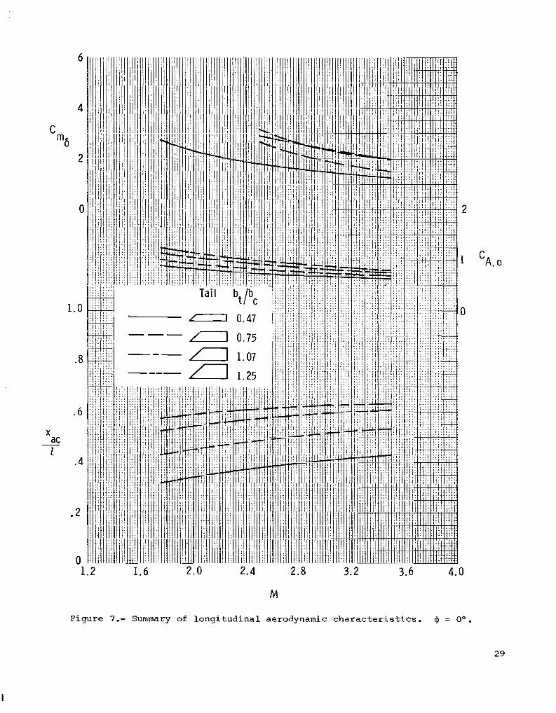
The summary o f l ong i tud ina l ae rodynamic cha rac t e r i s t i c s o f each t a i l - f in con f ig - u r a t i o n t h a t i n c l u d e s a c r o s s p lo t of bt/bc i s p r e s e n t e d i n f i g u r e 7. The d a t a f o r M = 1.75 are taken from unpublished NASA d a t a . I n g e n e r a l , w i t h i n c r e a s e s i n t a i l span, there are i n c r e a s e s i n
Cm6 and 'A,o and a rearward movement of
6
aerodynamic-center locat ions. AS would be expected for the complete model, the t a i l configurations of larger span (e.g. , bt/bc _> 1.07) have less t rave l in aerodynamic center th roughout the tes t Mach number range.
La te ra l -Di rec t iona l Aerodynamic C h a r a c t e r i s t i c s
The e f f e c t s of t a i l - f i n s p a n on t h e c a n a r d r o l l - c o n t r o l c h a r a c t e r i s t i c s of t he model a t 4 = Oo, 26.57O, and 45O are p r e s e n t e d i n f i g u r e s 8 t o I O . Limited t a i l - o f f d a t a are a l s o shown. The canards are e f f e c t i v e r o l l - c o n t r o l d e v i c e s t h r o u g h o u t t he test Mach number and model angle-of-at tack and rol l -angle ranges for the reduced- t a i l - s p a n c o n f i g u r a t i o n s (e .g. , bt/bc 0.75) . In gene ra l , t he re i s a r educ t ion of c a n a r d r o l l c o n t r o l w i t h i n c r e a s e s i n t a i l span a t low ang les of a t t a c k . The complex f low f ie lds p roduced by the de f l ec t ed cana rd pane l s pas s ve ry c lose t o t he t a i l f i n s and induce ro l l ing moments of o p p o s i t e d i r e c t i o n t o t h o s e c r e a t e d by the canards . For ta i l -span configurat ions with bt /bc > 1.07, t h i s i n d u c e d r o l l is l a r g e enough t o c o u n t e r a c t t h e c a n a r d r o l l , i n e f f e c t p r o d u c i n g a t o t a l model r o l l i n g moment which i s n e g l i g i b l e , o r , i n some cases o p p o s i t e t o t h a t d e s i r e d ( r o l l r e v e r s a l ) . However, f o r I$ = Oo, i n c r e a s e s i n r o l l c o n t r o l o c c u r w i t h i n c r e a s e s i n t a i l - f i n s p a n a t t he h ighe r ang le s of a t t a c k .
The e f f e c t s of t a i l - f i n s p a n on yaw-con t ro l cha rac t e r i s t i c s of t he model a t 4 = Oo are p r e s e n t e d i n f i g u r e 1 1 . In genera l , fo r b t /bc 5 1 .07, i n c r e a s e s i n t a i l span a t low ang les o f a t t ack p roduce i nc reases i n cana rd yaw c o n t r o l and induced ro l l ing-moment coef f ic ien ts . For values of bt/bc grea te r than 1 .07 , the da ta ind i - cate t h a t a r e d u c t i o n i n yaw con t ro l occu r s .
The e f f e c t s of t a i l - f i n s p a n on l a t e r a l - d i r e c t i o n a l a e r o d y n a m i c c h a r a c t e r i s t i c s of the model a t 41 = 26.57O f o r z e r o c o n t r o l s e t t i n g s are shown i n f i g u r e 1 2 . The magnitude of induced rolling-moment coefficient, and yawing-moment c o e f f i c i e n t due t o model r o l l asymmetry i n c r e a s e s a t the low Mach numbers w i t h i n c r e a s e s i n t a i l - f i n span.
A summary of c a n a r d c o n t r o l e f f e c t i v e n e s s of each t a i l - f i n c o n f i g u r a t i o n a t a = Oo is p resen ted i n f i gu re 13 . In gene ra l , t he re is a n i n c r e a s e i n C and
m6
Cn6 w i t h i n c r e a s e s i n t a i l s p a n ( b t / b c 5 1.07) t ha t r ep resen t s f avorab le cana rd
downwash and sidewash t a i l loadings on t h e l a r g e r t a i l - f i n s p a n c o n f i g u r a t i o n s . For a c o n s t a n t t a i l - s p a n c o n f i g u r a t i o n t h e r e is the expec ted dec rease i n e f f ec t iveness w i t h i n c r e a s e s i n Mach number. For t h e test Mach number r ange , t he da t a i nd ica t e t h a t c a n a r d r o l l c o n t r o l a t low ang les of a t t a c k is f e a s i b l e on reduced ta i l - f in span conf igura t ions (b t /bc < - 0.75).
COMPARISON OF EXPERIMENTAL DATA AND THEORY
Theore t i ca l Methods
In r e f e rences 5 t o 7, two d i f f e r e n t classes of missile aeroprediction programs f o r c i r c u l a r b o d i e s were exe rc i sed by comparisons with tes t d a t a . I n a n e f f o r t t o expand and complement these data comparisons for missile c o n f i g u r a t i o n s i n t h e Sidewinder class, t es t data and theory comparisons are p r e s e n t e d i n t h i s paper. The
7
aeropredict ion programs appl ied were developed by Nielsen Engineering and Research, Inc. (NEAR) under government contract and are d e s c r i b e d i n d e t a i l i n r e f e r e n c e s 8 t o 12.
The f i r s t class of programs is essent ia l ly p re l iminary des ign programs that ob ta in fo rces and moments to p rov ide r ap id eng inee r ing p red ic t ions . (See r e f s . 8 and 9.) These programs use data bases augmented by analysis and include MISSILE1 and MISSILE2 a p p l i c a b l e t o missile conf igura t ions wi th axisymmetric bodies. Program MISSILE2 is a modified version of MISSILE1 with the major change being the incorpora- t i o n of a vortex-cloud model f o r t h e p r e d i c t i o n of a f t e r b o d y v o r t i c i t y .
The second class of aeropredict ion programs consis ts of the DEMON series which is a more sophis t ica ted research too l than programs MISSILE1 and MISSILE2. The DEMON programs u s e supersonic pane l methods and give detai led pressure loadings a long with fo rces and moments ( r e f . 1 0 ) . I n c l u d e d i n t h e DEMON series i s a s i m p l i f i e d v e r s i o n NSWCDM (derived from DEMON2) designed as a semiproduction missile ae ropred ic t ion program s p e c i a l i z e d t o s u p e r s o n i c missile configurat ions with axisymmetr ic bodies . However, un l ike DEMON2 which could only provide isolated component loads, program NSWCDM is automated to give overal l forces and moments f o r t h e e n t i r e missile conf ig- u ra t ion . For these reasons, program NSWCDM is u s e d i n t h i s paper.
Both classes of aeropredict ion programs provide estimates of s t a t i c l o n g i t u d i n a l and l a t e ra l -d i r ec t iona l ae rodynamic cha rac t e r i s t i c s a t h igh angles of a t tack and a r b i t r a r y r o l l a n g l e s ; t h e y a l s o t r a c k t h e v o r t i c e s from canard or wing s e c t i o n s t o t h e t a i l s ec t ions u s ing t he same vor tex method ( r e f s . 1 1 and 1 2 ) . A summary of t he m a j o r c h a r a c t e r i s t i c s of these programs (NSWCDM, MISSILEI, and MISSILE2) i s p resen ted in the appendix . Regions of Mach number a n d a s p e c t r a t i o of cana rd and t a i l - f in v a l i d i t y f o r t h e c u r r e n t MISSILE1 and MISSILE2 da ta bases are p r e s e n t e d i n f i g u r e A1 i n t he append ix .
Longi tudinal Aerodynamic C h a r a c t e r i s t i c s
Comparisons of expe r imen ta l and ana ly t i ca l l ong i tud ina l ae rodynamic cha rac t e r i s - t ics o f each t a i l - f in con f igu ra t ion a t model r o l l a n g l e s of Oo and 45O a t M = 2.50 are p r e s e n t e d i n f i g u r e s 1 4 and 15, respect ively. (Note that when both MISSILE codes p r e d i c t i d e n t i c a l v a l u e s , o n l y p r e d i c t i o n s from one code is shown.) In general, t he re is good agreement between tes t d a t a and t h e p r e d i c t i o n s of both programs MISSILE1 and MISSILE2, w i th be t t e r ag reemen t occu r r ing fo r t he l a rge r t a i l spans. For the t a i l configurat ion bt /bc = 1.25 ( f i g . 1 5 ( d ) ) , MISSILE1 and MISSILE2 predic- t i ons d ive rge a t the h igher angles of a t tack probably because of d i f f e r e n t a f t e r b o d y vor t i c i ty mode l s . Program NSWCDM p r o v i d e s a c c u r a t e p r e d i c t i o n s f o r t a i l conf igura- t i o n s bt/bc 1.07 but underpredicts both normal-force and pitching-moment coef- f i c i e n t s f o r t h e bt/bc 5 0.75 span ( l onge r t i p cho rds ) con f igu ra t ions a t t he h ighe r angles o f a t tack .
P i t ch -con t ro l compar i sons fo r each t a i l - f in con f igu ra t ion a t 4 = Oo are pre- sen ted i n f i gu re 16 . Again, the codes are i n good agreement with the measured values e x c e p t f o r NSWCDM which underest imates pi tching-moment coeff ic ient for the smaller span configurat ions and overest imates it f o r t a i l conf igu ra t ion bt/bc = 1.25 a t t h e h igher angles of a t t a c k .
A summary comparison of experimental and analyt ical canard pi tch-control effec- t i veness of e a c h t a i l - f i n c o n f i g u r a t i o n a t Q = Oo i s shown i n f i g u r e 1 7 . The tes t va lue of f o r M = 1.75 w a s obtained from unpublished NASA data . In genera l ,
c m 6 8
the code estimates a re r ea sonab ly accu ra t e fo r t he test Mach number range, an excep- t i on be ing fo r MISSILE1 which underestimated for conf igura t ions b t /bc 1 -07 .
c"s In an a t t empt t o isolate and/or improve the load predictions of program NSWCDM
t h a t were underestimated for t a i l configurat ions bt /bc 5 0.75, missile-component l oad ing con t r ibu t ions w e r e eva lua ted . The measured load data for canard panel 2 a lone i n the presence of the body a r e p r e s e n t e d i n f i g u r e 18. Program NSWCDM e s t i - mates a r e i n good agreement with the tes t d a t a a t M = 2.50, b u t t h i s program over- p red ic t s t he measu red va lues a t t he h ighe r ang le s of a t t a c k a t M = 3.50. I n gen- eral, program MISSILE2 u n d e r p r e d i c t s t h e p a n e l l o a d s a t t h e h i g h e r a n g l e s of a t t a c k fo r bo th Mach numbers. It might be pointed out that M = 3.50 f a l l s o u t s i d e t h e v a l i d Mach number range for both predict ion codes. (See the appendix.)
Comparisons between test d a t a and load pred ic t ions for two t a i l - f i n p a n e l s i n the p resence of t h e body a re p re sen ted i n f igure 19 . It should be noted tha t these test d a t a were no t ob ta ined from d i r e c t t a i l - p a n e l measured loads; rather, the tes t d a t a shown are t h e d i f f e r e n c e i n normal-force coefficients between the body-tail and the body-alone configurations and include body upwash and car ryover e f fec ts . The p r e d i c t i o n s a l s o i n c l u d e t h e s e i n t e r f e r e n c e e f f e c t s . I n the upper par t of f igure 19 , program NSWCDM underpredic t s the normal - force coef f ic ien ts for the bt/b, = 0.47 and 0.75 t a i l p a n e l s which have the l onge r t i p cho rds . It is b e l i e v e d t h a t f o r t h e s e l o n g e r t i p - c h o r d p a n e l s , e s p e c i a l l y a t h i g h e r a n g l e s of a t tack , nonl inear s ide-edge suc t ion l oad ing becomes a primary source of normal fo rce . Adding the e s t ima ted normal-force coefficient increment produced by the s ide-edge vortex does br ing the h igh-angle-of -a t tack pred ic t ions up t o t h e t e s t - d a t a l e v e l of the reduced span ta i ls ; however, t h e r e is a s l i g h t o v e r p r e d i c t i o n f o r t h e l a r g e r t a i l s p a n s . I t a p p e a r s t h a t t he ove ra l l pane l l oad p red ic t ions of NSWCDM would be improved by including s ide-edge e f fec ts €or the reduced-span longer - t ip -chord f ins . I n the lower par t of f igure 19 , program MISSILE2 p r e d i c t i o n s a r e i n very good ag reemen t w i th t e s t da t a .
Comparisons of t e s t d a t a w i t h p r e d i c t i o n s from program NSWCDM for the complete model w i th t a i l con f igu ra t ions b t /bc = 0.47 and 1.25 a t M = 2.50 a r e shown i n f i g u r e 20. I n a d d i t i o n t o t h e m i s s i l e component loadings a l ready d i scussed , non- l i nea r a f t e rbody l oads due t o c r o s s f low drag were a l s o e s t i m a t e d . A s imple a lgebra ic equat ion der ived from crossf low theory was used to ob ta in the normal - force coef - f ic ien t increment p roduced by the a f te rbody c ross f low separa t ion . Adding t h e e s t i - mated normal-force coeff ic ient increments due to both the s ide-edge vortex and a f t e r - body v iscous c ross f low separa t ion br ing the p red ic t ions wi th in reasonable agreement t o t h e measured d a t a f o r t a i l - f i n c o n f i g u r a t i o n b t / b c = 0.47. However, wi th the a d d i t i o n of these increments , NSWCDM o v e r p r e d i c t s t h e t e s t d a t a of t a i l - f i n c o n f i g - urat ion bt /bc = 1.25, especially pitching-moment coefficient. These increments are p re sen t ly be lng i nco rpora t ed i n an updated version of NSWCDM t h a t w i l l be c a l l e d program LRCDM2.
La te ra l -Di rec t iona l Aerodynamic C h a r a c t e r i s t i c s
Rol l cont ro l . - A compar ison of exper imenta l and ana ly t ica l ro l l -cont ro l charac- t e r i s t i c s of e a c h t a i l - f i n c o n f i g u r a t i o n a t M = 2.50 f o r 9 = Oo is p r e s e n t e d i n f i g u r e 21. The p r e d i c t i o n s from program NSWCDM a r e i n good agreement with t e s t d a t a a t t h e lower angles of a t tack ( a < 8O) , e spec ia l ly fo r t a i l conf igu ra t ion bt/bc = 0.47. However, t he p red ic t ions d ive rged from tes t d a t a a t t h e h i g h e r a n g l e s of a t tack. In general , the overal l agreement of program NSWCDM with test d a t a is much be t te r than tha t p roduced by e i t h e r programs MISSILE1 o r MISSILE2. Both MISSILE codes underpredict roll cont ro l and g ive similar p r e d i c t i o n s up t o a n g l e s of a t t a c k
9
of about 1 O o , where they diverge from each other. This divergence trend, which i s a l s o e x h i b i t e d by the yawing-moment c o e f f i c i e n t estimates, begins a t the angle o f a t t a c k where both programs s tar t p red ic t ing a f t e rbody vo r t i c i ty . Fo r ang le s o f a t t a c k above l o o , t h e s e t r e n d s r e f l e c t t h e e f f e c t s o f d i f f e r e n t a f t e r b o d y v o r t i c i t y models contained in each program. (See ref . 11 f o r a b r i e f desc r ip t ion o f t he vo r t ex models . ) Since the ta i l - f ins-off predict ions f rom a l l three computer programs are i n exce l l en t ag reemen t w i th l imi t ed t a i l - f in s -o f f t es t da ta ( f lagged symbols in f i g . 2 1 ( d ) ) , it appears t h a t improvements are needed i n a l l t h r e e c o d e s t o p r e d i c t more a c c u r a t e l y the t a i l - f i n l o a d i n g s .
Yaw cont ro l . - A comparison of experimental and analytical yaw-control charac- t e r i s t i c s of e a c h t a i l - f i n c o n f i g u r a t i o n a t M = 2.50 f o r 4 = 0' is p r e s e n t e d i n f i g u r e 22. In general, program NSWCDM p r e d i c t i o n s are i n good agreement with test da ta , the yaw c o n t r o l and induced roll ing-moment predictions becoming e x c e l l e n t w i t h i n c r e a s e s i n t a i l span fo r ang le s of a t t a c k up t o a b o u t 1 2 O . Of t he VISSILE codes, MISSILE2 r e f l e c t s t h e same p red ic t ion t r ends as program NSWCDM except MISSILE2 under- predicts the low-angle-of-at tack induced rol l ing moments. The e r ra t ic behavior of MISSILE1 p r e d i c t i o n s a t the h igher angles of a t t a c k f o r t a i l conf igu ra t ion bt/bc = 0.47 may be due t o t h e a f t e r b o d y v o r t i c i t y model t h a t t h i s code uses. MISSILE1 underpredic t s yaw con t ro l and i nduced ro l l i ng moment f o r t h e l a r g e r t a i l spans a t the lower angles of a t t a c k .
Asymmetric r o l l o r i e n t a t i o n . - Comparisons of t es t d a t a and p r e d i c t i o n s of t he l a t e r a l - d i r e c t i o n a l a e r o d y n a m i c c h a r a c t e r i s t i c s of s e l e c t e d t a i l - f i n c o n f i g u r a t i o n s a t M = 1.75 f o r I$ = 26.57' are p r e s e n t e d i n f i g u r e 23. The p red ic t ion t r ends o f program NSWCDM genera l ly fo l low those of t he tes t da t a . The estimates of the MISSILE codes overpredict the measured data a t the h igher angles o f a t tack .
Rol l -control and yaw-control effect iveness . - Summary comparisons of test d a t a and a n a l y t i c a l c a n a r d r o l l - and yaw-control effectiveness of each t a i l - f in con f igu ra - t i o n a t 4 = 0' and 01 = 0' are p r e s e n t e d i n f i g u r e s 24 and 25, r e spec t ive ly . For t h e test Mach number range , the p red ic t ions of r o l l - c o n t r o l e f f e c t i v e n e s s from pro- gram NSWCDM ( f i g . 2 4 ) are i n v e r y good agreement wi th the t es t da ta and re f lec t the r o l l r e v e r s a l t r e n d s of t a i l conf igu ra t ions bt/bc 2 1.07. In general , canard rol l - c o n t r o l e f f e c t i v e n e s s is underpredicted by both MISSILE codes and for t a i l configura- t i o n s bt/bc 2 1.07 is underpredicted even more a t the lower Mach numbers. MISSILE1 code estlmates a r e a l i t t l e b e t t e r t h a n MISSILE2 estimates f o r t a i l c o n f i g u r a t i o n s b /b > 0.75. P red ic t ions of canard yaw-control effectiveness from a l l of the codes ( f ig . 25 ) are i n good agreement with t es t d a t a . t , c -
Sch l i e ren pho tographs . - In an a t t empt t o v i sua l i ze cana rd -gene ra t ed f l ow f i e lds , schl ieren photographs of t a i l configurat ions bt /bc < 1.07 with canard yaw c o n t r o l a t M = 1.75 are shown i n f i g u r e 26. In general , th i s f i g u r e shows t h a t t h e most dominant feature a t a = 0' r e s u l t s f rom the vor tex o r ig ina t ing a t t he t ips of the v e r t i c a l c a n a r d s which are loaded due t o t h e yaw con t ro l . For t a i l conf igu ra t ions bt/bc 5 0.75 i n p a r t i c u l a r , t h e s e c a n a r d t i p v o r t i c e s clear the t a i l f ins , whereas f o r t a i l conf igu ra t ion bt/bc = 1 .07 , t h e r e i s evidence of vortex flow impingement on the t a i l f i n s . ( S e e f i g . 2 6 ( c ) .) It is b e l i e v e d t h a t t h i s impingement reduces the bene f i c i a l cana rd downwash and s idewash induced ta i l - f in loadings tha t he lp to produce model p i t c h and yawing moments. For each t a i l - f i n c o n f i g u r a t i o n , v o r t i c e s emanating from both tips of t he ve r t i ca l and ho r i zon ta l cana rds pas s ve ry c lose t o the t a i l f i n s as the angle of a t t a c k i n c r e a s e s . These canard vortices, which include downwash and s idewash , resu l t in the loading and un loading of i n d i v i d u a l t a i l f i n s wi th changes in angle of a t tack . In the lower por t ion of f i g u r e 2 6 ( a ) , p r e d i c t e d t i p v o r t e x t r a j e c t o r i e s o f t h e c a n a r d are superimposed on t h e t e s t - d a t a v o r t i c e s of t a i l
10
conf igu ra t ion bt/bc = 0.47. From the s i d e view, t h e s e MISSILE1 p r e d i c t i o n s are shown to be in exce l l en t ag reemen t w i th t he t e s t da ta . S ince a l l t h r e e p r e d i c t i o n c o d e s p r e s e n t e d i n t h i s paper u s e t h e same vor t ex t r ack ing method, MISSILE1 may be an indicator of their accuracies; however , the predict ion methods of de te rmining the i n f l u e n c e s on ta i l - f in loadings p roduced by the cana rd gene ra t ed f l ow f i e lds are i n need of improvement, as i l l u s t r a t e d by the comparisons made i n f i g u r e 2 1 ( d ) .
CONCLUSIONS
An experimental wind-tunnel invest igat ion has been conducted a t Mach numbers from 1.60 t o 3.50 to ob ta in t he l ong i tud ina l and l a t e ra l -d i r ec t iona l ae rodynamic c h a r a c t e r i s t i c s of a c i r cu la r , c ruc i fo rm, cana rd -con t ro l l ed missile w i t h v a r i a t i o n s in t a i l - f in span . In add i t ion , compar i sons were made wi th the experimental aerody- namic c h a r a c t e r i s t i c s u s i n g t h r e e missile aeropredict ion programs: MISSILEl, MISSILE2, and NSWCDM. The r e s u l t s o f t h e i n v e s t i g a t i o n are as fol lows:
1 . For t h e tes t Mach number r ange , t he da t a i nd ica t e t ha t cana rd roll c o n t r o l a t l o w ang le s o f a t t ack i s f e a s i b l e on t a i l - f in con f igu ra t ions w i th t a i l - t o -cana rd span r a t i o s less than or equa l t o 0.75.
2. The canards are e f f e c t i v e p i t c h and yaw c o n t r o l d e v i c e s on each t a i l - f in span c o n f i g u r a t i o n t e s t e d .
3. Programs MISSILE1 and MISSILE2 provide very good p red ic t ions o f l ong i tud ina l ae rodynamic cha rac t e r i s t i c s and f a i r p red ic t ions o f l a t e ra l -d i r ec t iona l ae rodynamic c h a r a c t e r i s t i c s a t low ang les o f a t t ack , w i th MISSILE2 p r e d i c t i o n s g e n e r a l l y i n bet ter agreement with tes t d a t a .
4. Program NSWCDM provides good longi tudina l and la te ra l -d i rec t iona l aerodynamic p r e d i c t i o n s t h a t i m p r o v e w i t h i n c r e a s e s i n t a i l - f i n s p a n . E s t i m a t e s o f r o l l i n g - moment c o e f f i c i e n t a r e i n good agreement with tes t d a t a a t low angles of a t t a c k .
5. Programs MISSILEI, MISSILE2, and NSWCDM a p p e a r t o be acceptab le engineer ing d e s i g n t o o l s € o r a e r o p r e d i c t i o n a n d , i n g e n e r a l , make reasonable estimates of t he tes t data; however, these programs need to be m o d i f i e d i n o r d e r t o bet ter p r e d i c t t h e l a t e ra l -d i r ec t iona l ae rodynamic cha rac t e r i s t i c s a t h ighe r ang le s of a t t a c k ( g r e a t e r than 12O).
Langley Research Center Nat ional Aeronaut ics and Space Adminis t ra t ion Hampton, VA 23665 May 2, 1983
11
APPENDIX
AEROPREDICTION PROGRAMS
This appendix summar izes major charac te r i s t ics o f the ana ly t ica l p rograms.
NSWCDM
The aeropredict ion program NSWCDM calcu la tes de ta i led aerodynamic loadings and p r e s s u r e d i s t r i b u t i o n s a c t i n g on missile conf igu ra t ions i nc lud ing monoplane, c r u c i f o r m , a n d i n t e r d i g i t a t e d l i f t i n g s u r f a c e s mounted on b o d i e s w i t h c i r c u l a r c r o s s sec t ions . Ca lcu la t ions are based on paneling methods i n which supersonic l inear t heo ry so lu t ions are used. Vortex s t rengths and posi t ions are c a l c u l a t e d by empirical and vortex t racking methods. The Mach number range is from 1.3 t o a b o u t 3 .O. The angle of a t t a c k is up t o 20' with a v a r i a b l e model r o l l a n g l e .
MISSILE1 and MISSILE2
The aeropredict ion programs MISSILE1 and MISSILE2 p r e d i c t s ta t ic long i tud ina l , d i r e c t i o n a l , and l a t e ra l aerodynamic charac te r i s t ics o f c ruc i form missile conf igu ra t ions w i th c i r cu la r bod ie s . P red ic t ion t echn iques man ipu la t e empirical aerodynamic da ta r e t r i e v e d from a data base. Externa l vor tex in f luences are computed and superimposed on t h e missile. Vor tex s t rengths and pos i t ions are c a l c u l a t e d by empirical and vortex tracking methods. The Mach number range i s from 0.8 t o 3 .O and angle of a t t a c k is up t o 45' with a v a r i a b l e model r o l l a n g l e . For t h e c u r r e n t data base, t h e r e is a r e s t r i c t i o n i n f i n aspect r a t i o w i t h Mach number. Mach number and a spec t - r a t io r eg ions o f va l id i ty are p r e s e n t e d i n f i g u r e A1 .
4
3
A R 2
1
I 2 M
3 4
Figure A1 .- Mach number and f i n aspect r a t i o r e g i o n s of v a l i d i t y € o r c u r r e n t MISSILE1 and MISSILE2 da ta bases .
1 2
REFERENCES
1. C o r l e t t , William A.; and Howell, Dorothy T.: Aerodynamic C h a r a c t e r i s t i c s a t Mach 0.60 t o 4.63 of TWO Cruciform Missile Models, One Having Trapezoidal Wings w i t h Canard Controls and the O t h e r Having Delta Wings With Tail Controls . NASA TM X-2780, 1973.
2. Blair , A. B., Jr.: Aerodynamic Characteristics of a Tandem-Canard Missile a t Mach Numbers From 1 .83 t o 4.63. NASA TM X-3040, 1974.
3. Burt , James R., Jr.: The Ef fec t iveness of Canards fo r Ro l l Con t ro l . Tech. R e p . RD-77-8, U.S. Army, Nov. 1976. (Available from DTIC as AD A037 077.)
4. mpp , G. H.: performance Improvements With Sidewinder Missile Airframe Variants. AIM Paper 79-0091, Jan. 1979.
5. Blair , A. B., Jr.; and Rapp, G. H.: Experimental and Analyt ical Comparison of Aerodynamic Charac t e r i s t i c s o f a Forward-Control Missile. AIAA-80-0374, Jan. 1980.
6. Allen, Jerry M.: Comparison of Analyt ical and Experimental Supersonic Aerody- namic Charac t e r i s t i c s o f a Forward Control Missile. AIAA-81-0398, Jan. 1981.
7. Allen, Jerry M.; and Bla i r , A. B., Jr.: Comparison of Ana ly t i ca l and Experi- mental Supersonic Aerodynamic C h a r a c t e r i s t i c s of a Forward Control Missile. J. Spacecr. & Rockets, vol. 19, no. 2, Mar.-Apr. 1982, pp. 155-1 59.
8. Nielsen, Jack N.; Hemsch, Michael J.; and Smith, Charles A.: A Prel iminary Method f o r C a l c u l a t i n g t h e Aerodynamic Characteristics of Cruciform Missiles t o High Angles of Attack Including Effects of Rol l Angle and Control Deflections. ONR-CR215-226-4F, U.S. Navy, Nov. 1 , 1977. (Avai lab le from DTIC a s AD A054 349. )
9. Smith, C. A.; and Nielsen, J. N.: F inal Report - Pred ic t ion of Aerodynamic C h a r a c t e r i s t i c s of Cruciform Missiles t o High Angles of Attack Utilizing a Dis t r ibu ted Vor tex Wake. NEAR TR 208 (Cont rac t N60921-79-C-A049), Nielsen Eng. & R e s . , Inc., Jan. 1980.
10. Di l lenius , M. F. E.; and Smith, C. A.: F ina l Repor t - Program NSWCDM, Aerody- namic P red ic t ion Program for Cruciform Canard-Axisymmetric Body-Cruciform T a i l Missiles a t Supersonic Speeds. NEAR TR 217 (Con t rac t No. N70921-79-C-A365), Nielsen Eng. & R e s . , Inc. , A p r . 1980.
1 1 . Hemsch, Michael J.; and Nielsen, Jack N.: S t a tus Repor t on Tr i se rv ice Data Base Extension of PROGRAM MISSILE. Proceedings of the Twelfth Navy Symposium on A e r o b a l l i s t i c s - Volume I, U.S. N a v y , May 1981, pp. 1-107 - 1-1 15.
12. Di l lenius , M. F. E.; Hemsch, M. J.; Sawyer, W. C.; Allen, J. M.; and B l a i r , A. B., Jr.: Comprehensive Missile Aerodynamics Programs for Pre l iminary Design. AIAA-82-0375, Jan. 1982.
13. Standard for Metric P rac t i ce . E 380-79, American SOC. Tes t ing & Mater., c.1980.
13
14. Jackson, Charlie M., Jr.; Corlett, William A.; and Monta, William J.: Descrip- t ion and Cal ibra t ion of the Langley Uni ta ry P lan Wind Tunnel. NASA TP-1905, 1981.
15 . S t a l l i ngs , Robert L., Jr.; and L a m b , Milton: Effects of Roughness S i z e on t h e P o s i t i o n of Boundary-Layer Trans i t ion and on the Aerodynamic C h a r a c t e r i s t i c s of a 55O Swept Delta Wing a t Supersonic Speeds. NASA TP-1027, 1977.
14
I
TABLE I.- GEOMETRIC CHARACTERISTICS OF CANARD AND TAIL-FIN CONFIGURATIONS
TF-4 canard: Exposed root chord. c m ( i n . ) ....................................... 11.123 (4.379) Tip chord. c m ( i n . ) ................................................ 3.338 (1.314) mposed taper r a t i o ......................................................... 0.300 Exposed span. c m ( i n . ) ............................................. 14.463 (5.694)
Maximum th ickness . c m ( i n . ) ........................................ 0.508 (0.200) Exposed aspect r a t i o ........................................................ 2.00 Leading-edge sweep. deg ..................................................... 47.1 Hinge l i ne . pe rcen t roo t cho rd .............................................. 57.0
Exposed planform area. a c m 2 ( i n 2 ) ................................ 104.561 ( 1 6.207)
Tails f i n s : Configurat ion bt/bc = 0.47:
Exposed root chord. c m ( i n . ) ..................................... 21.590 (8.500) Tip chord. c m ( i n . ) .............................................. 18.204 (7.167) Exposed taper r a t i o ....................................................... 0.843 Exposed span. c m ( i n . ) ........................................... 6.772 (2.666) Exposed planform area. a c m 2 ( i n 2 ) .............................. 134.735 (20.884) Thickness. c m ( i n . ) .............................................. 0.231 (0.091) Exposed a s p e c t r a t i o ...................................................... 0.34 Leading-edge sweep. deg ................................................... 45.0
Exposed root chord. c m ( i n . ) ..................................... 21.590 (8.500) Tip chord. c m ( i n . ) .............................................. 16.167 (6.365)
Exposed span. cm ( i n . ) ........................................... 10.846 (4.270) Exposed planform area. a c m 2 ( i n 2 ) .............................. 204.748 (31.736)
Configuration bt/bc = 0.75:
Exposed taper r a t i o ....................................................... 0.749
Thickness. c m ( i n . ) .............................................. 0.231 (0.091) Exposed a s p e c t r a t i o ...................................................... 0.58 Leading-edge sweep. deg ................................................... 45.0
Configurat ion bt/bc = 1.07: Exposed root chord. c m ( i n . ) ..................................... 21.590 (8.500) T i p chord. c m ( i n . ) .............................................. 13.863 (5.458) Exposed t a p e r r a t i o ....................................................... 0.642 Exposed span. c m ( i n . ) ........................................... 15.453 (6.084) Exposed planform area. a c m 2 ( i n 2 ) .............................. 273.935 (42.460) Thickness. c m ( i n . ) .............................................. 0.231 (0.091) Exposed a s p e c t r a t i o ...................................................... 0.87 Leading-edge sweep. deg ................................................... 45.0
Exposed root chord. c m ( i n . ) ..................................... 21.590 (8.500) Tip chord. c m ( i n . ) .............................................. 12.550 (4.941)
Exposed span. c m ( i n . ) .......................................... 18.080 (7.1118) Exposed planform area. a c m 2 ( i n 2 ) .............................. 308.625 (47.837)
Configurat ion bt/bc = 1.25:
Exposed t a p e r r a t i o ....................................................... 0.581
Thickness. c m ( i n . ) .............................................. 0.231 (0.091) Exposed a s p e c t r a t i o ...................................................... 1.06 Leading-edge sweep. deg ................................................... 45.0
aExposed planform area i s t h e area formed when two exposed panels of the canard o r t a i l f i n are jo ined t oge the r .
15
102.31 (40.28) <
< (10.60)
f18.13) Moment center
( a ) Complete model with t a i l f i n s bt/bc = 0.47.
t
Figure 1.- Model d e t a i l s . ~ l l dimensions are g iven i n cen t ime te r s ( i nches ) un le s s o the rwise i nd ica t ed .
0.51 ( 0.20)
1.45
7 .'24 (2.85)
TF-4 canard
Tail bJbc Tip chord Sernispan
0.47 18.21 (7.17) 3.38 (1.33)
(b) Canard and t a i l fins.
Figure 1 .- Concluded.
17
683-85
Figure 2.- Model with t a i l f i n s bt/b, = 1.07.
C
.4
. 3
.2
.1
0 -8 -4 0 4 12 16 20
Figure 3.- Typical var ia t ion of measured balance-chamber axial-force coefficient with angle of a t t ack . Complete model wi th t a i l - f in conf igura t ion bt/b, = 0.47 and zero cont ro l def lec t ion .
24
=, deq
( a ) M = 2.50.
Figure 4.- E f f e c t s of t a i l - f i n s p a n on long i tud ina l ae rodynamic cha rac t e r i s t i c s a t 4 = Oo.
20
20
0
-20
-40
Cm -60
-80
-100
-120
-140
24
20
16
12
'N *
4
0
-4
-8 -8 -4 0 4 8 12 16 20 24 28 3;
0 > deg
(b) M = 3.00.
Figure 4 .- Continued.
21
0. deg
(c) M = 3.50.
Figure 4 .- Concluded .
22
20
0
-20
-40
C, -60
-80
-100
-1 20
-140
24
20
16
12
'N 8
4
0
-4
-8 -8 -4 0 4 8 12 16 20 24 28 32
0 , deg
C A
( a ) M = 2.50.
23
-8 -4 0 4 8 12 16 20 24 28 32
0, deg
(b) M = 3.00.
Figure 5 .- Continued.
24
" .. . .. . ... . .
20
5
-20
-40
C, -65
-80
-100
-125
-140
24
20
16
12
‘N
4
0
-a
-8 -8 -4 0 4 8 12 16 20 24 28 32
5 , deg
( C ) M = 3.50.
Figure 5 .- Concluded.
25
Figure 6.-
26
Ef f 'ects o f t a i l - f in span on pitch-control characterist ics at
&pitch = 5 0 .
oo .
16 20
I3 bt/ bc
0.47
0.75
1.07
1.25
2
1 'A
0
32
M = 3.00.
Figure 6 .- Continued.
27
I I I I i 1 . 1 I I I
Tail b,
(c) M = 3.50.
Figure 6 .- Concluded.
28
C n "6
1
X - ac
1
.o
.8
. 6
.4
, 2
0
2
0
1.2 1.6 2.0 2.4 2.8 3.2 3.6 4.0
M
Figure 7.- Summary of l ong i tud ina l ae rodynamic cha rac t e r i s t i c s . @ = O o .
29
-3
J n "6
1
0 .2 Tai l f ins off
4 .6 .8 1.0
bt I b c
Figure 7 .- Concluded.
1.2 1.4
30
-8
=4 1 Tai l fins O f f
0 4 16 20
(a) M = 1.75.
24 28 32
Figure 8.- Effects of tail-fin span on roll-control characteristics at I$ = 0 ' .
6r011 = -1 oo .
31
-8 -4 0 4 8 12 16 20 24 28 32
a, deg
(b) M = 2.50.
Figure 8 .- Continued.
2
1
0
-1
-2
32
-8 -4 0 4 8 12 16 20 24 28 32
0, deg
(c) M = 3.00.
Figure 8 .- Continued.
33
-8 -4 0 4 8 12 16 20 24 28 32
a, deg
( d ) M = 3 .50 .
Figure 8 .- Concluded.
34
c"
4
0
-4
-8
-12
-16
-8 -4 0 4 8 12 16 20 24 28 32
a, deg
( a ) M = 1.75.
Figure 9.- Effects of t a i l - f in span on roll-control characterist ics a t 6 = 26.57O.
6r011 = - loo .
35
2
1
O
-1
-2
36
-8 -4 0 4 8 12 16 20 24 28 32
a , d e l
(b) M = 2.50.
Figure 9 .- Continued.
(c) M = 3.00.
Figure 9 .- Continued.
37
-8 -4 0 4 8 12 16 20 24 28 32
0, deg
(d) M = 3.50.
Figure 9 .- Concluded.
38
4
0
-4
'n
-a
-12
-16
Tail bt/ bc
0 0.47
0 0.75
0 1.07
A fl 1.25 I
I '
/ I 'ai l fins off I
I
4
! 2
0
cy -2
-4
-6
I
I
2 4 2 8
( a ) M = 1.75.
Figure 10.- Effects of t a i l - f in span on rol l -control character is t ics a t Q = 45O.
%-011 = -100.
39
-8 -4 0 4 8 12 16 20
0, deg
(b) M = 2.50.
Figure 10 .- Continued.
24 28 32
40
I . .. . . .
-8 -4 0 4 8 12 16 20 24 28 32
a, deg
(c) M = 3.00.
Figure 10 .- Continued.
41
-8 -4 0 4 8 12 16 20 24 28 32
a, deg
(d) M = 3.50.
Figure 10 .- Concluded.
42
4
0
-4
c" -8
-12
-16
43
-a -4 0 4 a
2
1
0
-1
-2
28 32
(b) M = 3.00.
Figure 1 1 .- Continued.
44
4
0
-4
C" -8
-12
-16
- 20
L
(
c -; Y
-1
2
1
0 C l
-1
-2
- 8 - 4 2 8 32 4
M = 3.50.
Figure 1 1 .- Concluded.
45
Figure 12.- Effects of t a i l - f in span on lateral-directional aerodynamic cha rac t e r i s t i c s a t 4 = 26.57O.
46
-8 -4 0 4 8 12 16 20 24 28 32
0, deg
(b) M = 2.50.
Figure 12.- Continued.
47
-8 -4 0 4 8 12 16 20 24 28 32
a, deg
(c) M = 3.00.
Figure 12.- Continued.
48
4
0
-4
5-l
- 8
-12
-16
I
[
'4
-8 -4 0 4 8 12 16 20 24 28 32
a. deg
( d ) M = 3.50.
Figure 1 2 .- Concluded.
49
C m6
C n 6
C
1.2 1.6 2.0 2.4 2.8 M
3.2 3.6 4.0
Figure 13.- Summary of canard cont ro l e f fec t iveness of e a c h t a i l - f i n c o n f i g u r a t i o n a t 6 = Oo. a = O o .
50
C m6
C
6
4
2
0
.3
. 2
.1
0
-
Ta i
1
I fins off 2 .4
bt Ibc
1.0 1.2
C
Figure 1 3 .- Concluded.
51
20 24 28 32
( a ) bt/bc = 0.47.
Figure 14.- Comparison of experimental and analyt ical longi tudinal aerodynamic c h a r a c t e r i s t i c s of e a c h t a i l - f i n c o n f i g u r a t i o n a t @ = Oo. M = 2.50.
52
(b) bt/b, = 0 .75 .
Fi’gure 14.- Continued.
53
(c) bt/b, = 1.07.
Fiqclre 14.- Continued.
54
28 32
(d) bt /bc = 1.25 .
Figure 1 4. - Concluded.
55
-8 -4 0 4 8 12 16 20 24 28 32
a, deg
( a ) bt/bc = 0.47.
Figure 15.- Comparison of experimental and ana ly t ica l longi tudina l aerodynamic c h a r a c t e r i s t i c s of e a c h t a i l - f i n c o n f i g u r a t i o n a t (I = 45". M = 2.50.
56
16 20 24 28 32
(b) bt/b, = 0.75.
Figure 15 .- Continued.
57
20
0
-20
-40
'c m -60
-80
-100
-120
24
20
16
12
CN 8
4
0
-A -, -8 -4 0 4 8 12 16 20 24 28 32
a, deg
(c) bt/b, = 1.07.
Figure 15.- Continued.
58
0 4 8 12 16
a , deg
(d) bt/b, = 1 e 2 5
Figure 1 5 .- Concluded.
59
I
-a -4 0 4 a
( a ) bt/bc = 0.47.
16 20 24
. . : I 4 . . . . . . ....
I
Figure 16.- Comparison of experimental and a n a l y t i c a l p i t c h - c o n t r o l c h a r a c t e r i s t i c s of each t a i l - f i n c o n f i g u r a t i o n a t @ = Oo. M = 2 .50 ; 'pitch = s o .
60
-4 0 4
( b ) bt/b, = 0.75.
20 24 32
Figure 16.- Continued.
61
-8 -4 0 16 24 28 32
(c) bt/bc = 1 -07 .
Figure 16.- Continued.
62
( d ) bt/bc = 1 .25.
Figure 16.- Concluded.
6 3
a bt/ bc = 0.75
4 t 3 I-
" b
2 -
0 Test data
NSWCDM "- MI SSI LE2
--- MISSILE1
-
1 -
0 ' I
.I 3 - C I
2 l-
1 -
0 , I I 1.0 1.5 2.0 2.5 3.0 3.5 4.0 1.0 1.5 2.0 2.5 3.0 3.5 4.0
M M
Figure 17.- Summary comparison of experimental and analytical canard pitch- c o n t r o l e f f e c t i v e n e s s of e a c h t a i l - f i n c o n f i g u r a t i o n a t @ = O o .
1.0 - 0 Test data
NSWCDM - 0 -
BM
-1.0 -
-2.0 -
HM
c~~
. 4 - -
0 -
- .4 -
2.0 -
/- -1.0 I 1
-8 -4 0 4 8 12 16 20 a . deg
c
c
1 I -8 -4 0 4 8 12 16 20
a. deg
( a ) M = 2.50. (b) M = 3.50.
Figure 18.- Comparison of experimental and analytical canard loads (canard panel 2) i n presence of body a t $I = O o . Zero cont ro l def lec t ion .
20
16
12
cN
8
4
0
20
16
12
cN
8
4
0 Test data Tail alone ( 2 panels) NSWCDM
ref = Body cross-sectional area, A ”- NSWCDM + CN,VSE
0.47
0 Test data
MI SSI LE2
0 0 0 0 4 8 12 16 20 a, deg
Figure 1 9 .- Comparison of experimental and analytical normal-force coefficients for t a i l alone (two panels) i n presence of body a t 4 = Oo. M = 2.50.
66
-8 -4 0 4 8 12 16
a. deg
20 24 28 32
( a ) bt/bc = 0.47.
Figure 20.- Comparison of expe r imen ta l and ana ly t i ca l for complete model with bt/bc = 0.47 and 1 .25
aerodynamic c h a r a c t e r i s t i c s a t 6 = O o . M = 2.50.
67
-8 -4 0 4 8 12 16 20 24 28 32
a, deg
( b ) bt/bc = 1 .25.
Figure 20.- Concluded.
68
"
8
4
0
C" -4
-8
-12
-16
2
0
c y -2
-4
-6 I -8
Figure 21 .-
\
I
4 j I i t
( a ) bt/bc = 0.47.
I c
i I
-1-
t
r -
\
20
0 Test data NSWCDM
-" MISSILE2
_" MISSILE1
j i i I
I
! !
I
1 1
24
! -
I I
28 32
Comparison of e x p e r i m e n t a l a n d a n a l y t i c a l r o l l - c o n t r o l c h a r a c t e r i s t i c s of e a c h t a i l - € i n c o n f i g u r a t i o n f o r = -100 a t Q = Oo. M = 2.50. 6r011
69
-8 -4
:I
16 20 .. ! -
0 Test data
NSWCDM "_ MISSILE2
"_ MISSILE1
28
3
2
1
CZ
0
-1
-2
32
(b ) bt/b, = 0.75.
Figure 21 .- Continued.
70
8
4
0
-4
C"
-8
-12
-16
-20
2
0
c y -2
-4
-6 -8 0 4
( c ) bt/b, = 1.07.
0 Test data
NSWCDM "_ MISSILE2
"_ MISSILE1
24 32
Figure 21 .- Continued.
71
I
a, deg
( d ) bt/b, = 1.25.
Figure 21 .- Concluded.
72
4
0
-4
c" -8
-12
-16
2
0
-2
-4
-6 -8 -4 0 16
bt/bc = 0.47.
20 24
3
2
1
0
-1
-2
-3
Figure 22.- Comparison of experimental and analyt ical yaw-control character is t ics of each tail-fin configuration f o r 6 = -so a t 4 = Oo. M = 2.50.
Yaw
73
-8 -4 0 4 12 16 20 24 28 32
0, deg
( b ) bt/b, = 0.75.
Figure 22. - Continued.
74
4
0
-4
C"
-8
-12
-16
2
[
-1
1
-I
-a -4 0 12 16
0 Test data NSWCDM
" - MI S S I LE2 I ~ _
"_ MI SSI LE1 I 1
20 24 F 28
2
1
0 cz
-1
-2
32
(c) bt/bc = 1 -07
Figure 22.- Continued.
75
-8 -4 0 4
1 .25.
24 28
2
1
c1
-1
-2
Figure 22.- Concluded.
76
8
4
0
C" -4
-8
-12
-16
2
0
-2
-4
-6 16 20 24 28 32
( a ) bt/bc = 0.75.
F igure 23.- Comparison of expe r imen ta l and ana ly t i ca l l a t e ra l -d i r ec t iona l ae rodynamic c h a r a c t e r i s t i c s of s e l e c t e d t a i l - f i n c o n f i g u r a t i o n s a t 4 = 26.57O. M = 1.75.
77
8
4
0
-4
c" -8
-12
-16
-20
4
2
0
-2
-4
-6 -8 -4 4
bt/b, = 1.07.
0 Test data
_"
/ . .
. . . . . . . .
20
3
2
1
0
-1
-2
Figure 23.- Continued.
78
-a 0 a 16
"-
20 24 28 32
bt/b, = 1.25.
Figure 23. - Concluded.
79
.15
.10
.05
C
0
-. 05
-. 10
- a 11 c b b = 0.75
-
- :lo """"- """"_
-
I
.20 r I
I bt'bc = 0.47
.15 1
O t -.05 1 1 1
1.0 1.5 2.0 2.5 3.0 3.5 4.0 M
-0 bt/bc = 1.25
0 Test data
NSWCDM
M I SSI LE2
MISSILE1
- "- -"
M
Figure 24.- Summary comparison of experimental and analyt ical canard rol l -control e f f e c t i v e n e s s of each ta i l - f i n c o n f i g u r a t i o n a t 4 = Oo . a = Oo .
Figure 25.- Summary comparison of experimental and analytical canard yaw-control e f f ec t iveness of each ta i l - f in conf igura t ion a t 4 = Oo . a = o0 .
a = O 0
a = 8 0
Canard vortex trajectories
a = O 0
a = 8 0
Predicted canard t ip vortex t ra jector ies (MISSILEI)
683-86 ( a ) bt/bc = 0.47.
Figure 26.- Schl ie ren photographs o f se lec ted t a i l - f in conf igura t ions wi th canard yaw con t ro l . 4 = 0' ; M = 1.75; = -50.
yaw
82
01 = 0.0'
u = 4.0'
a = 0.0'
a = 4.0'
u = 8.0'
( b ) bt/bc = 0.75.
a = 8.0'
L-83-87 ( c ) bt/bc = 1.07.
Figure 26 .- Concluded.
83
-
1. Report No. ~~ ~-
- I 2. Government Accession No.
NASA TP-2157 4. Title and Subtitle
EFFECT O F T A I L - F I N SPAN ON STABILITY AND CONTROL CHARACTERISTICS OF A CANARD-CONTROLLED MISSILE AT SUPERSONIC MACH NUMBERS
. .
7. Author(s) . .
~~
A. B. Blair , Jr., Je r ry M. Allen, and Gloria Hernandez
. . -
9. Performing Organization Name and Address
NASA Langley Research Center Hampton, VA 23665
2. Sponsoring Agency Name and Address ~.
National Aeronautics and Space Administration Washington, DC 20546
5. Supplementary Notes ."
" ~ -_ . . "
6. Abstract " .
3. Recipient's C a t a l o g No.
5. Report Date
June 1983 6. Performing Organization Code
505-43-23-02 -
8. Performing Organization Report No.
L-15586 10. Work Unit No.
11. Contract or Grant No.
13. Type of Report and Period Covered
Technical Paper 14. Sponsoring Agency Code
"
An experimental wind-tunnel investigation has been conducted a t Mach numbers from 1 .60 t o 3.50 to obtain the longi tudinal and l a t e ra l -d i r ec t iona l aerodynamic charac- t e r i s t i c s of a circular, cruciform, canard-controlled missile with variations i n t a i l - f in span . I n addition, comparisons were made with the experimental aerodynamic character is t ics using three missi le aeropredict ion programs: MISSILE1 , MISSILE2, and NSWCDM. The r e s u l t s of t he i nves t iga t ion i nd ica t e t ha t €o r t he t e s t Mach number range, canard r o l l c o n t r o l a t low angles of a t tack is f eas ib l e on ta i l - f in conf iqura- t ions with tai l- to-canard span ratios of less than or equal to 0.75. The canards are e f f ec t ive p i t ch and yaw control devices on each tail-fin span configuration tested. Programs MISSILE1 and MISSILE2 provide very good predict ions of longitudinal aero- dynamic c h a r a c t e r i s t i c s and fa i r p red ic t ions of l a t e ra l -d i r ec t iona l aerodynamic c h a r a c t e r i s t i c s a t low angles of a t tack, wi th MISSILE2 predict ions general ly i n b e t t e r agreement with t e s t d a t a . Program NSWCDM provides good longitudinal and l a t e ra l -d i r ec t iona l aerodynamic predictions that improve with increases i n t a i l - f i n span. Estimates of rolling-moment coe f f i c i en t a r e i n good agreement with test data a t low angles of a t t ack . Programs MISSILEl, MISSILE2, and NSWCDM appear t o be acceptable engineering design tools for aeroprediction and, in general , make rea- sonable estimates of t h e t e s t d a t a ; however, these programs need t o be modified i n o rder to be t te r p red ic t the l a te ra l -d i rec t iona l aerodynamic c h a r a c t e r i s t i c s a t higher angles of a t tack (grea te r than 1 2 ' ) .
. . ~~
I . Key Words (Suggested by Authorls)) 18. Distribution Statement " .