27
CiA Draft Standard Proposal 304 CANopen Framework for Safety-Relevant Communication Version 1.0 Date: 01.01.2001 ' CAN in Automation e. V.

CiA Draft Standard Proposal 304
CANopenFramework for Safety-Relevant Communication
Version 1.0
Date: 01.01.2001
© CAN in Automation e. V.
CiA DSP 304 V 1.0 CANopen Framework for Safety-Relevant Communication CiA e.V.
- 2 -
Table of contents
1 Tables .....................................................................................................................................................3
2 Figures....................................................................................................................................................4
3 Scope......................................................................................................................................................5
4 References .............................................................................................................................................6
5 Definitions and abbreviations ................................................................................................................7
6 Theory of safe operation........................................................................................................................8
7 Basic communication.............................................................................................................................9
8 Safety-relevant communication .......................................................................................................... 10
8.1 Safety-relevant data object (SRDO) ............................................................................................ 10
8.1.1 Timing requirements.......................................................................................................... 10
8.1.2 SRDO services .................................................................................................................. 11
8.1.3 SRDO protocol................................................................................................................... 12
8.2 Global failsafe command (GFC)................................................................................................... 12
8.2.1 Global failsafe command usage........................................................................................ 12
8.2.2 Global failsafe command service...................................................................................... 13
8.2.3 Global failsafe command protocol .................................................................................... 13
8.3 Network initialisation and system boot-up ................................................................................... 14
8.3.1 Initialisation procedure for safety networks ...................................................................... 14
8.3.2 Network states for safety nodes........................................................................................ 15
8.3.3 Pre-defined connection set ............................................................................................... 16
8.4 Object dictionary ........................................................................................................................... 17
8.4.1 Specification of additional complex data types ................................................................ 17
8.4.2 Communication profile specification ................................................................................. 17
9 Annex................................................................................................................................................... 25
9.1 Hardware....................................................................................................................................... 25
9.2 Configuration mechanism............................................................................................................. 26
9.3 Mathematical analysis of CANopen Safety ................................................................................. 26
9.4 Limits and recommendations ....................................................................................................... 27
9.5 Rules of implementation ............................................................................................................... 27

CiA DSP 304 V 1.0 CANopen Framework for Safety-Relevant Communication CiA e.V.
- 3 -
1 Tables
Table 1: Write SRDO ................................................................................................................................... 11
Table 2: States and communication objects ............................................................................................... 15
Table 3: Broadcast objects of the pre-defined connection set................................................................... 16
Table 4: Peer-to-peer objects of the pre-defined connection set............................................................... 16
Table 5: SRDO communication parameter record ..................................................................................... 17
Table 6: Safety communication objects ...................................................................................................... 17
CiA DSP 304 V 1.0 CANopen Framework for Safety-Relevant Communication CiA e.V.
- 4 -
2 Figures
Figure 1: Example of a CANopen network with safe nodes......................................................................... 9
Figure 2: Example for SCT timing ............................................................................................................... 10
Figure 3: Example for SRVT timing............................................................................................................. 11
Figure 4: Write SRDO protocol.................................................................................................................... 12
Figure 5: Write GFC protocol....................................................................................................................... 13
Figure 6: Flow chart of the network initialisation process for safety networks .......................................... 14
Figure 7: Structure of SRDO COB-ID entry ................................................................................................ 18
Figure 8: One transceiver and two CAN controllers, redundant mC for SIL 2 and SIL 3 (IEC 61508) orAK 4 and AK 6 (DIN V VDE 801) (C-Model /3/).......................................................................... 25
Figure 8: Principle of a safe configuration................................................................................................... 26
CiA DSP 304 V 1.0 CANopen Framework for Safety-Relevant Communication CiA e.V.
- 5 -
3 Scope
The CANopen Framework Safety-Relevant Communication is intended to be an add on to theCANopen Application Layer and Communication Profile (see /1/).
It is assumed, that a device with the need of safety-relevant communication can use all the otherfeatures defined by the communication profile. Safety is an additional property of such devices. Onlyspecial communication objects support safety, all other objects remain normal. The manufacturer andthe system integrator shall take care, that the safety requirements are allocated to safe communicationobjects, that the hardware and software of the device support the safety function and that the device isoperated within its safe limits.
This framework describes only the data transport mechanism on a CANopen network, that allows theexchange of safety-relevant data.
Due to CANopen compatibility communication is limited to 64 safe communication objects, so up to 64suppliers of safety-relevant objects can operate in a CANopen network. The number of consumers ofthe safety-relevant objects is not defined (at least one receiver is necessary).

CiA DSP 304 V 1.0 CANopen Framework for Safety-Relevant Communication CiA e.V.
- 6 -
4 References
/1/ CiA DS-301 Version 4.01, CANopen Application Layer and Communication Profile, June 2000
/2/ Charzinsiki, Bewertung der Fehlersicherungsverfahren im CAN-Protokoll, Universit�t Stuttgart,1991
/3/ FAET; FAEM III, BIA, Pr�fung und Zertifizierung von ÒBussysteme f�r die �bertragungsicherheitsrelevanter NachrichtenÓ, Stand 28.05.2000
/4/ IEC 61508, International standard, Functional safety of electrical / electronic / programmableelectronic safety-related systems
/5/ DIN V VDE 0801, Grunds�tze f�r Rechner in Systemen mit Sicherheitsaufgaben
/6/ EN954-1 Safety related parts of control systems, Part 1: General principles of design

CiA DSP 304 V 1.0 CANopen Framework for Safety-Relevant Communication CiA e.V.
- 7 -
5 Definitions and abbreviations
BIA
Berufsgenossenschaftliches Institut f�r Arbeitssicherheit - Institute for occupational safety ofaccident insurance institutions
COB-ID
Communication object-identifier
GFC
Global failsafe command, short and high priority message to ensure fast system reaction(event driven, not safe)
NMT
Network management
Refresh-time
Configurable time of the periodic SRDO transmission in a source of safety-relevantinformation, allows to test the ->SCT in the safety node
RTR
Remote transmission request; property of CAN, every node can initiate a specific transmissionof any other node by a remote request
Safety controller
safety relevant output node, that controls a safety-relevant process (e.g. a possibly dangerousmotion). A safety controller has to survey all corresponding safety input nodes
SCT
Safeguard cycle time, configurable time to fulfill the native time expectation of a specific safetyapplication
SRDO
Safety-relevant data object; only mechanism to transport safe data in an CANopen network
SRVT
Safety-relevant object validation time; configurable time for the correct reception of a SRDO ina given safety application
T�V
Technischer �berwachungsverein - German Association for Technical Inspection
SIL
Safety integrity level
AK
Anforderungsklassen - Requirement classes

CiA DSP 304 V 1.0 CANopen Framework for Safety-Relevant Communication CiA e.V.
- 8 -
6 Theory of safe operation
It is absolutely essential for a possibly safe system, that there is a safe state. Then as a reaction to anemergency command, an alarm or an error, the safe state can be entered.
It is also important, that the functionality of the safeguard measures is regularly checked. A singledefect in a safety-relevant communication must not override the safety circuitry! If such an erroroccurs, it must be detected within a short period of time in which a 2nd error is unlikely to happen.
All the systems, especially the safety-relevant circuitry must have a high reliability in order to extendthe time-span between the safety-tests and minimize the down time of the whole system (e.g. if one ofredundant components fails, the system has to be shut off). So the need for safety decreases theavailability of a system.
The idea of safety in CAN communication is not to ensure, that there are absolutely no errors andfaults. This would be rather hard to proof - anyway. The goal is to detect all possible errors and reactin a predictable (safe) way.
In a safe CAN system there are sources of safe information (e.g. safety switches, light barriers,emergency stop buttons) and consumers of such information (e.g. relay, valve or drive controlling apossibly dangerous movement, safety PLC). As the "consumers" control the possible dangeroussituation it is responsible for entering the safe state after any safety relevant interference. It also has tocheck the data integrity of the safety-relevant communication.
So the "consumers" are the safety controllers in a possibly safe CANopen system.
As the sources (safety inputs) are the origin of safe communication objects (SRDOs), their number islimited to 64. The number of safety controllers is not limited in theory, as CAN allows many consumersto listen to the same SRDO(s), i.e. many actuator devices can use the same information.
As the safety controllers are responsible for the data integrity and actuality, every safety-relevantoutput device has to survey all corresponding sources of safety data.
CiA DSP 304 V 1.0 CANopen Framework for Safety-Relevant Communication CiA e.V.
- 9 -
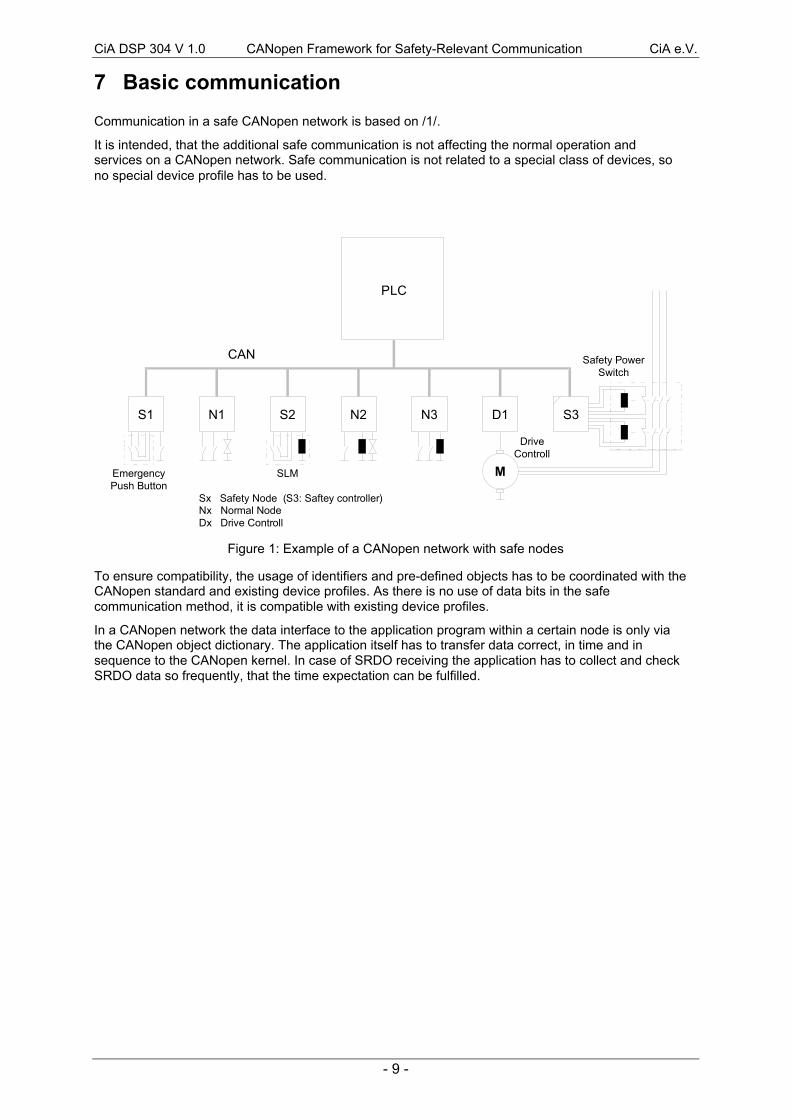
7 Basic communication
Communication in a safe CANopen network is based on /1/.
It is intended, that the additional safe communication is not affecting the normal operation andservices on a CANopen network. Safe communication is not related to a special class of devices, sono special device profile has to be used.
PLC
S1 N1 S2 N2 N3 D1
MEmergencyPush Button
SLM
DriveControll
CAN Safety PowerSwitch
S3
Sx Safety Node (S3: Saftey controller)Nx Normal NodeDx Drive Controll
Figure 1: Example of a CANopen network with safe nodes
To ensure compatibility, the usage of identifiers and pre-defined objects has to be coordinated with theCANopen standard and existing device profiles. As there is no use of data bits in the safecommunication method, it is compatible with existing device profiles.
In a CANopen network the data interface to the application program within a certain node is only viathe CANopen object dictionary. The application itself has to transfer data correct, in time and insequence to the CANopen kernel. In case of SRDO receiving the application has to collect and checkSRDO data so frequently, that the time expectation can be fulfilled.

CiA DSP 304 V 1.0 CANopen Framework for Safety-Relevant Communication CiA e.V.
- 10 -
8 Safety-relevant communication
8.1 Safety-relevant data object (SRDO)
The safety-relevant data transfer is performed by means of "safety-relevant data objects (SRDO)".
An SRDO shall consist of two CAN data frames with identifiers, which shall be different in at least twobit positions. The user data in both transmissions is redundant, i.e. the meaning of the data is thesame, but the data on the 2nd transmission is inverted bitwise.
SRDOs shall be transmitted periodically. If required, SRDOs may also be transmitted event-driven,e.g. to ensure fast reaction after a safety critical change on the input. RTR is not possible, SRDOs areonly allowed in the network state "Operational".
An SRDO is only valid, if both CAN frames are received properly (without failure and in time). Theredundant transmission is sent after the first transmission to the CAN controller with minimum delay.
There are two kinds of use for SRDOs. The first is data transmission and the second data reception. Itis distinguished by the information direction. Devices where the information direction is set totransmitÊ(tx) are SRDO producer and devices where the information direction is set to receiveÊ(rx) arecalled SRDO consumer. SRDOs are described by the SRDO communication parameter (26h) and theSRDO mapping parameter. The structure of this data type is explained in 8.3. The SRDOcommunication parameter describes the communication capabilities of the SRDO. The SRDOmapping parameter contains information about the content of the SRDOs (device variables). Theindices of the corresponding Object Dictionary entries are computed by the following formulas:
SRDO communication parameter index = 1300h + SRDO-number
SRDO mapping parameter index = 1380h + SRDO-number
For each SRDO the pair of communication and mapping parameter is mandatory. The entriesmentioned above are described in 8.4.
8.1.1 Timing requirements
As SRDOs shall be transmitted periodically in order to test the correct function of the safety-relevantcommunication on the CAN bus, the so called safeguard cycle time (SCT) is to be defined. It shall besurvived by the safety controller.
SRDO
refreshtime
SRDO
refreshtime
SRDO
refreshtime
SCTSCT
SCT
! SCT expired!!!
t
Figure 2: Example for SCT timing
A second test determines, if there is sufficient network capacity for a safety system. Both frames of anSRDO shall be received correctly within the given safety-relevant validation time (SRVT). Normallyboth frames are transmitted with minimum delay. If the 2nd frame is not being received within SRVT,the bus system has reduced transmission capabilities. The reaction time on a safety relevant eventcould be enlarged.

CiA DSP 304 V 1.0 CANopen Framework for Safety-Relevant Communication CiA e.V.
- 11 -
SRDO
t
SRDO SRDO SRDO?
SRVT SRVT SRVT SRVT
SRVTexpired
Figure 3: Example for SRVT timing
8.1.2 SRDO services
SRDO transmission follows the producer/consumer relationship in /1/ and consits of two CAN dataframes.
Attributes:
· SRDO number: SRDO number [1..64] for every user type on the local device· user type: one of the values {consumer, producer}· data type: according to the SRDO mapping· refresh-time: n*1 ms, n > 0· validation-time: n*1 ms, n > 0
8.1.2.1 Write SRDO
For the write SRDO service the push model is valid. There are one or more consumers of a SRDO. ASRDO shall have exactly one producer.
Through this service the producer of a SRDO sends the data of the mapped application object to theconsumer(s).
Table 1: Write SRDO
Parameter Request / Indication
ArgumentSRDO numberData
Mandatorymandatorymandatory
8.1.2.2 Read SRDO
The read SRDO service is not allowed.
CiA DSP 304 V 1.0 CANopen Framework for Safety-Relevant Communication CiA e.V.
- 12 -
8.1.3 SRDO protocol
8.1.3.1 Write SRDO protocol
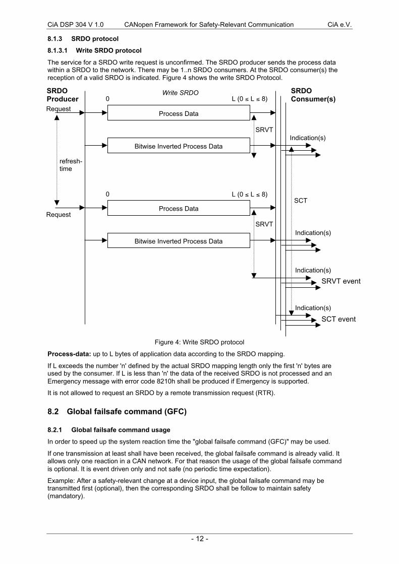
The service for a SRDO write request is unconfirmed. The SRDO producer sends the process datawithin a SRDO to the network. There may be 1..n SRDO consumers. At the SRDO consumer(s) thereception of a valid SRDO is indicated. Figure 4 shows the write SRDO Protocol.
Figure 4: Write SRDO protocol
Process-data: up to L bytes of application data according to the SRDO mapping.
If L exceeds the number 'n' defined by the actual SRDO mapping length only the first 'n' bytes areused by the consumer. If L is less than 'n' the data of the received SRDO is not processed and anEmergency message with error code 8210h shall be produced if Emergency is supported.
It is not allowed to request an SRDO by a remote transmission request (RTR).
8.2 Global failsafe command (GFC)
8.2.1 Global failsafe command usage
In order to speed up the system reaction time the "global failsafe command (GFC)" may be used.
If one transmission at least shall have been received, the global failsafe command is already valid. Itallows only one reaction in a CAN network. For that reason the usage of the global failsafe commandis optional. It is event driven only and not safe (no periodic time expectation).
Example: After a safety-relevant change at a device input, the global failsafe command may betransmitted first (optional), then the corresponding SRDO shall be follow to maintain safety(mandatory).
Process Data
Bitwise Inverted Process Data
Process Data
Bitwise Inverted Process Data
SRDOProducer
SRDOConsumer(s)
Write SRDO
refresh-time
SCT
SRVT
SRVT
Request
Indication(s)
Request
Indication(s)
0 L (0 £ L £ 8)
0 L (0 £ L £ 8)
Indication(s)
Indication(s)
SRVT event
SCT event
CiA DSP 304 V 1.0 CANopen Framework for Safety-Relevant Communication CiA e.V.
- 13 -
8.2.2 Global failsafe command service
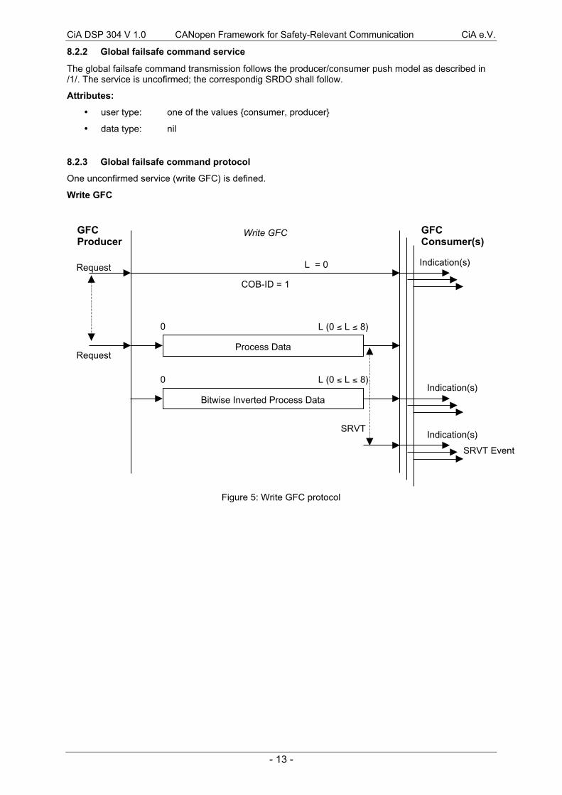
The global failsafe command transmission follows the producer/consumer push model as described in/1/. The service is uncofirmed; the correspondig SRDO shall follow.
Attributes:
· user type: one of the values {consumer, producer}
· data type: nil
8.2.3 Global failsafe command protocol
One unconfirmed service (write GFC) is defined.
Write GFC
Figure 5: Write GFC protocol
Process Data
GFCProducer
GFCConsumer(s)
Write GFC
Request Indication(s)
Request
L = 0
0 L (0 £ L £ 8)
COB-ID = 1
Bitwise Inverted Process DataIndication(s)
0 L (0 £ L £ 8)
Indication(s)SRVT
SRVT Event

CiA DSP 304 V 1.0 CANopen Framework for Safety-Relevant Communication CiA e.V.
- 14 -
8.3 Network initialisation and system boot-up
8.3.1 Initialisation procedure for safety networks
In Figure 6 the general flow chart of the network initialisation process, controlled by a NMT masterapplication or configuration application is shown.
Figure 6: Flow chart of the network initialisation process for safety networks
In step A the devices are in the node state PRE-OPERATIONAL which is entered automatically afterpowerÐon. In this state the devices are accessible via their default SDO using identifiers that shallbeen assigned according to the pre-defined connection set. In this step the configuration of deviceparameters take place on all nodes which support parameter configuration. Some configuration datamight be safety-relevant. So additional measures shall be taken, to ensure the safety function in thenetwork.
This is done from a configuration application or tool which resides on the node that is the client for thedefault SDOs. For devices that support these feature the selection and/or configuration of PDOs, themapping of application objects (PDO mapping), the selection and/or configuration of SRDOs, themapping of application objects (SRDO mapping), the configuration of additional SDOs and optionallythe setting of COB-IDs may be performed via the default SDO objects.
In many cases a configuration is not necessary as default values are defined for all application andcommunication parameters.
If the application requires the synchronisation of all or some nodes in the network, the appropriatemechanisms may be initiated in the optional step B. It may be used to ensure that all nodes exceptsafety nodes are synchronised by the SYNC object before entering the node state OPERTAIONAL instep E. The first transmission of SYNC object starts within 1 sync cycle after entering thePREÐOPERATIONAL state.
In step C node guarding may be activated (if supported) using the guarding parameters configured instep A.
In step D there shall be a method performed for the check of the autenticy of the configuration data. Itcovers the following safety relevant configuration entries:
· SRDO numbers(s) used
· Time expection (refresh time for TX, SCT for RX and the SRVT between two telegrams )
· Information direction
· Mapping parameter
Configuration of all device parameters,including communication parameters
(via default SDO)
(Optional)Start transmission of SYNC, wait for
synchronisation of all devices
(Optional)Start of node guarding
Verify safetyconfiguration parameters
Setting of all nodes tothe operational state
A
B
C
D
E
CiA DSP 304 V 1.0 CANopen Framework for Safety-Relevant Communication CiA e.V.
- 15 -
The checksum of the respective configuration entries shall be defined, that the safe application maycheck if a safety configuration tool has been used and that the content of the configuration entries hasnot been changed in state OPERATIONAL. In case of mismatch the safety node shall not transmitSRDOs; the safety controller shall be enter (stay) in safe state.
8.3.2 Network states for safety nodes
The "safe state" of a device is not a CANopen communication state and falls not in this scope.
8.3.2.1 Pre-operational
In the PRE-OPERATIONAL state, communication via SDOs is possible, however SRDO and PDOcommunication is not allowed. Configuration of SRDOs, PDOs, device parameters and also theallocation of application objects (PDO mapping) may be performed by a configuration application. Thenode may be switched into the OPERATIONAL state directly by sending a Start_Remote_Noderequest. In the PRE-OPERATIONAL state the application is in the safe state.
8.3.2.2 Operational
In the OPERATIONAL state SRDO, PDO and NMT communication objects are active, however objectdictionary access via SDO is not possible. For the safe application this is the only working state (e.g.motor on). Safety communication is only supported in this state.
8.3.2.3 Stopped
By switching a safety device in the STOPPED state communication is limited to receiving the NMTobject. The application shall be in the safe state.
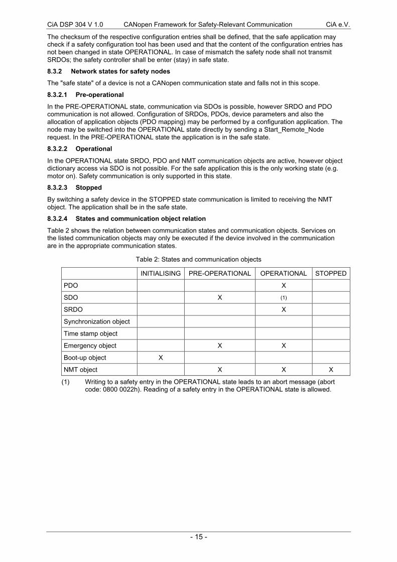
8.3.2.4 States and communication object relation
Table 2 shows the relation between communication states and communication objects. Services onthe listed communication objects may only be executed if the device involved in the communicationare in the appropriate communication states.
Table 2: States and communication objects
INITIALISING PRE-OPERATIONAL OPERATIONAL STOPPED
PDO X
SDO X (1)
SRDO X
Synchronization object
Time stamp object
Emergency object X X
Boot-up object X
NMT object X X X
(1) Writing to a safety entry in the OPERATIONAL state leads to an abort message (abortcode: 0800 0022h). Reading of a safety entry in the OPERATIONAL state is allowed.

CiA DSP 304 V 1.0 CANopen Framework for Safety-Relevant Communication CiA e.V.
- 16 -
8.3.3 Pre-defined connection set
In order to reduce configuration effort for simple networks a mandatory default identifier allocationscheme is in /1/ defined.
This pre-defined connection set is extended to support one SRDO for every safety node with aNodeÐID between 1 and 64. Devices with a Node-ID, which is higher than 64, shall not have pre-defined COB-ID assigned.
Table 3: Broadcast objects of the pre-defined connection set
object function code(binary)
resulting COBÐIDs Communicationparameters at index
GFC 0000 001h -
Table 4: Peer-to-peer objects of the pre-defined connection set
resulting COBÐIDsobject
functioncode
(binary) normal data complement data
Communicationparameters at index
channeldirection
SRDO(Node-ID 1 - 32)
0010257 - 319(1)
(101h - 13Fh)258 - 320(1)
(102h - 140h)1301h tx
SRDO(Node-ID 33 - 64)
0010321 - 383(1)
(141h - 17Fh)322 - 384(1)
(142h - 180h)1301h rx
(1) Every second COB-ID is used.
CiA DSP 304 V 1.0 CANopen Framework for Safety-Relevant Communication CiA e.V.
- 17 -
8.4 Object dictionary
8.4.1 Specification of additional complex data types
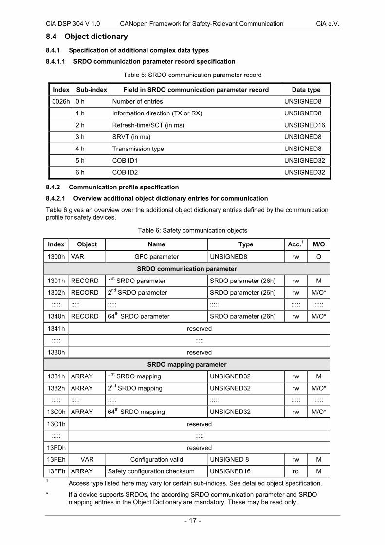
8.4.1.1 SRDO communication parameter record specification
Table 5: SRDO communication parameter record
Index Sub-index Field in SRDO communication parameter record Data type
0026h 0 h Number of entries UNSIGNED8
1 h Information direction (TX or RX) UNSIGNED8
2 h Refresh-time/SCT (in ms) UNSIGNED16
3 h SRVT (in ms) UNSIGNED8
4 h Transmission type UNSIGNED8
5 h COB ID1 UNSIGNED32
6 h COB ID2 UNSIGNED32
8.4.2 Communication profile specification
8.4.2.1 Overview additional object dictionary entries for communication
Table 6 gives an overview over the additional object dictionary entries defined by the communicationprofile for safety devices.
Table 6: Safety communication objects
Index Object Name Type Acc.1 M/O
1300h VAR GFC parameter UNSIGNED8 rw O
SRDO communication parameter
1301h RECORD 1st SRDO parameter SRDO parameter (26h) rw M
1302h RECORD 2nd SRDO parameter SRDO parameter (26h) rw M/O*
::::: ::::: ::::: ::::: ::::: :::::
1340h RECORD 64th SRDO parameter SRDO parameter (26h) rw M/O*
1341h reserved
::::: :::::
1380h reserved
SRDO mapping parameter
1381h ARRAY 1st SRDO mapping UNSIGNED32 rw M
1382h ARRAY 2nd SRDO mapping UNSIGNED32 rw M/O*
::::: ::::: ::::: ::::: ::::: :::::
13C0h ARRAY 64th SRDO mapping UNSIGNED32 rw M/O*
13C1h reserved
::::: :::::
13FDh reserved
13FEh VAR Configuration valid UNSIGNED 8 rw M
13FFh ARRAY Safety configuration checksum UNSIGNED16 ro M1 Access type listed here may vary for certain sub-indices. See detailed object specification.
* If a device supports SRDOs, the according SRDO communication parameter and SRDOmapping entries in the Object Dictionary are mandatory. These may be read only.

CiA DSP 304 V 1.0 CANopen Framework for Safety-Relevant Communication CiA e.V.
- 18 -
8.4.2.2 Detailed specification of additional communication profile specific objects
Object 1300h: Global failsafe command parameter
OBJECT DESCRIPTION
INDEX 1300h
Name Global failsafe command parameter
Object code VAR
Data type UNSIGNED 8
Category Optional
ENTRY DESCRIPTION
Access rw
PDO mapping No
Value range0: GFC is not valid
1: GFC is valid
Default value 0
Object 1301h - 1340h: SRDO communication parameter
Contains the communication parameters for the SRDOs the device is able to receive or to transmit.The type of the SRDO communication parameter (26h) is described in 8.4.1.1.
The sub-index 0h contains the number of highest entry within the communication record.
At sub-index 1h resides the information direction of the SRDO. The SRDO information direction allowsto select if it is used as a receive SRDO or as a transmit SRDO in the operational state. There may beSRDOs fully configured (e.g. by default) but not used, and therefore set to "not valid" (deleted). Thefeature is necessary for devices supporting more than 1 SRDO, because each device with a Node-IDin the range from 1 to 64 has only default identifiers for the first SRDO. It is not allowed to change theCOB-ID 1 or COB-ID 2 while the SRDO exists (value unequal to 0).
Sub-index 2h contains the refresh-time or the SCT depending on the information direction (see 8.1.1).
Sub-index 3h contains the SRDO validation time, if it is a receive SRDO (see 8.1.1).
The transmission type (sub-index 4h) defines the transmission / reception character of the SRDO. It isdefined as type 254. /1/ describes the usage of this entry. On an attempt to change the value of thetransmission type an abort message (abort code: 0609 0030h) is generated.
At sub-index 5h and sub-index 6h resides the two COB-IDs of the SRDO. These entries were definedas UNSIGNED32 for compatibility reasons to the COB-ID definitions in /1/. The entry shall beinterpreted as defined in Figure 7. The COB-IDs may only be changed in the range from 101h to 180h.Every SRDO uses two following COB-IDs from this range, where the first COB-ID is odd and thesecond COB-ID is even.
UNSIGNED32
MSB LSB
bits 31 - 11 10 - 0
11-bit-ID reserved (=0) 11 bit identifier
Figure 7: Structure of SRDO COB-ID entry

CiA DSP 304 V 1.0 CANopen Framework for Safety-Relevant Communication CiA e.V.
- 19 -
OBJECT DESCRIPTION
INDEX 1301h - 1340h
Name SRDO communication parameter
Object code RECORD
Data type SRDO parameter
Category Conditional;
Mandatory for each supported SRDO
ENTRY DESCRIPTION
Sub-index 0h
Description Number of entries
Entry category Mandatory
Access ro
PDO mapping No
Value range 6
Default value 6
Sub-index 1h
Description Information direction
Entry category Mandatory
Access rw
PDO mapping No
Value range 0: does not exist / is not valid1: exists / is valid for transmit (tx)2: exists / is valid for receive (rx)3 - 255: reserved
Default value see: pre-defined connection set
Sub-index 2h
Description tx: refresh-time in ms
rx: SCT in ms
Entry category Mandatory
Access rw
PDO mapping No
Value range 1 - 65535
Default value tx: 25 ms
rx: 50 ms

CiA DSP 304 V 1.0 CANopen Framework for Safety-Relevant Communication CiA e.V.
- 20 -
Sub-index 3h
Description tx: not used
rx: SRDO validation time in ms
Entry category Conditional
Access rw
PDO mapping No
Value range 1 - 255
Default value 20 ms
Sub-index 4h
Description Transmission type
Entry category Mandatory
Access ro
PDO mapping No
Value range 254
Default value 254
Sub-index 5h
Description COB-ID 1
Entry category Mandatory
Access rw
PDO mapping No
Value range 257, 259 - 383
Default value Index 1301h: 0FFh + (2 x Node-ID),
Index 1302h - 1340h: disabled
Sub-index 6h
Description COB-ID 2
Entry category Mandatory
Access rw
PDO mapping No
Value range 258, 260 - 384,
Default value Index 1301h: 100h + (2 x Node-ID),
Index 1302h - 1340h: disabled
CiA DSP 304 V 1.0 CANopen Framework for Safety-Relevant Communication CiA e.V.
- 21 -
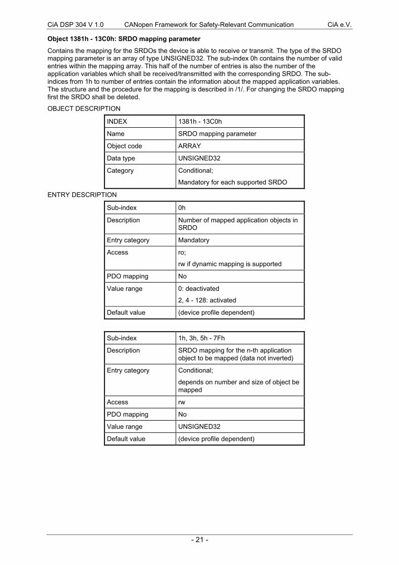
Object 1381h - 13C0h: SRDO mapping parameter
Contains the mapping for the SRDOs the device is able to receive or transmit. The type of the SRDOmapping parameter is an array of type UNSIGNED32. The sub-index 0h contains the number of validentries within the mapping array. This half of the number of entries is also the number of theapplication variables which shall be received/transmitted with the corresponding SRDO. The sub-indices from 1h to number of entries contain the information about the mapped application variables.The structure and the procedure for the mapping is described in /1/. For changing the SRDO mappingfirst the SRDO shall be deleted.
OBJECT DESCRIPTION
INDEX 1381h - 13C0h
Name SRDO mapping parameter
Object code ARRAY
Data type UNSIGNED32
Category Conditional;
Mandatory for each supported SRDO
ENTRY DESCRIPTION
Sub-index 0h
Description Number of mapped application objects inSRDO
Entry category Mandatory
Access ro;
rw if dynamic mapping is supported
PDO mapping No
Value range 0: deactivated
2, 4 - 128: activated
Default value (device profile dependent)
Sub-index 1h, 3h, 5h - 7Fh
Description SRDO mapping for the n-th applicationobject to be mapped (data not inverted)
Entry category Conditional;
depends on number and size of object bemapped
Access rw
PDO mapping No
Value range UNSIGNED32
Default value (device profile dependent)
CiA DSP 304 V 1.0 CANopen Framework for Safety-Relevant Communication CiA e.V.
- 22 -
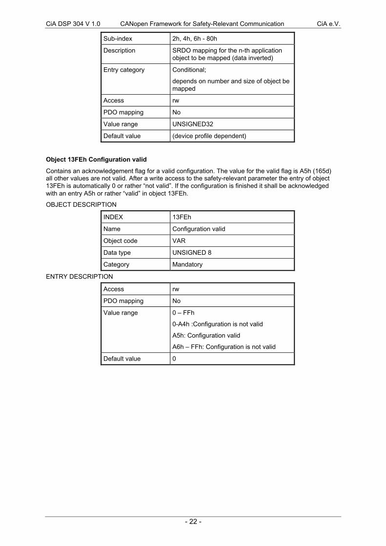
Sub-index 2h, 4h, 6h - 80h
Description SRDO mapping for the n-th applicationobject to be mapped (data inverted)
Entry category Conditional;
depends on number and size of object bemapped
Access rw
PDO mapping No
Value range UNSIGNED32
Default value (device profile dependent)
Object 13FEh Configuration valid
Contains an acknowledgement flag for a valid configuration. The value for the valid flag is A5h (165d)all other values are not valid. After a write access to the safety-relevant parameter the entry of object13FEh is automatically 0 or rather Ònot validÓ. If the configuration is finished it shall be acknowledgedwith an entry A5h or rather ÒvalidÓ in object 13FEh.
OBJECT DESCRIPTION
INDEX 13FEh
Name Configuration valid
Object code VAR
Data type UNSIGNED 8
Category Mandatory
ENTRY DESCRIPTION
Access rw
PDO mapping No
Value range 0 Ð FFh
0-A4h :Configuration is not valid
A5h: Configuration valid
A6h Ð FFh: Configuration is not valid
Default value 0
CiA DSP 304 V 1.0 CANopen Framework for Safety-Relevant Communication CiA e.V.
- 23 -
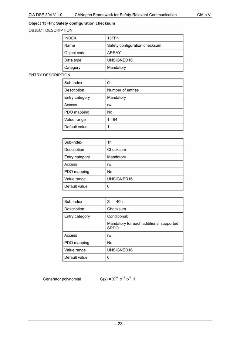
Object 13FFh: Safety configuration checksum
OBJECT DESCRIPTION
INDEX 13FFh
Name Safety configuration checksum
Object code ARRAY
Data type UNSIGNED16
Category Mandatory
ENTRY DESCRIPTION
Sub-index 0h
Description Number of entries
Entry category Mandatory
Access rw
PDO mapping No
Value range 1 - 64
Default value 1
Sub-index 1h
Description Checksum
Entry category Mandatory
Access rw
PDO mapping No
Value range UNSIGNED16
Default value 0
Sub-index 2h Ð 40h
Description Checksum
Entry category Conditional;
Mandatory for each additional supportedSRDO
Access rw
PDO mapping No
Value range UNSIGNED16
Default value 0
Generator polynomial G(x) = X16+x12+x5+1
CiA DSP 304 V 1.0 CANopen Framework for Safety-Relevant Communication CiA e.V.
- 24 -
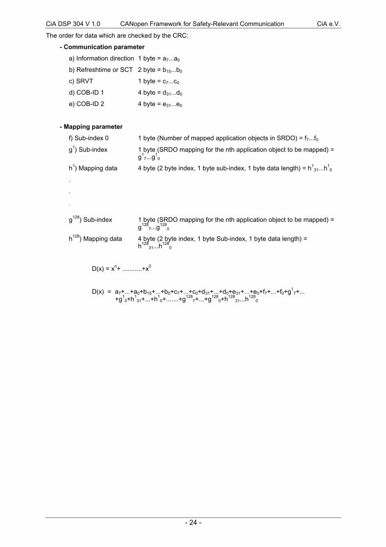
The order for data which are checked by the CRC:
- Communication parameter
a) Information direction 1 byte = a7...a0
b) Refreshtime or SCT 2 byte = b15...b0
c) SRVT 1 byte = c7...c0
d) COB-ID 1 4 byte = d31...d0
e) COB-ID 2 4 byte = e31...e0
- Mapping parameter
f) Sub-index 0 1 byte (Number of mapped application objects in SRDO) = f7...f0
g1) Sub-index 1 byte (SRDO mapping for the nth application object to be mapped) =g1
7...g1
0
h1) Mapping data 4 byte (2 byte index, 1 byte sub-index, 1 byte data length) = h131...h
10
.
.
.
g128) Sub-index 1 byte (SRDO mapping for the nth application object to be mapped) =g128
7...g128
0
h128) Mapping data 4 byte (2 byte index, 1 byte Sub-index, 1 byte data length) =h128
31...h128
0
D(x) = xn+ ...........+x0
D(x) = a7+...+a0+b15+...+b0+c7+...+c0+d31+...+d0+e31+...+e0+f7+...+f0+g17+...
+g10+h1
31+...+h10+.......+g128
7+...+g1280+h128
31...h128
0
CiA DSP 304 V 1.0 CANopen Framework for Safety-Relevant Communication CiA e.V.
- 25 -
9 Annex
9.1 Hardware
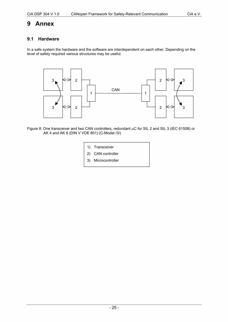
In a safe system the hardware and the software are interdependent on each other. Depending on thelevel of safety required various structures may be useful.
Figure 8: One transceiver and two CAN controllers, redundant mC for SIL 2 and SIL 3 (IEC 61508) orAK 4 and AK 6 (DIN V VDE 801) (C-Model /3/)
CAN
2
2
1
3
3
2
2
1
3
3
1) Transceiver
2) CAN controller
3) Microcontroller
CiA DSP 304 V 1.0 CANopen Framework for Safety-Relevant Communication CiA e.V.
- 26 -
9.2 Configuration mechanism
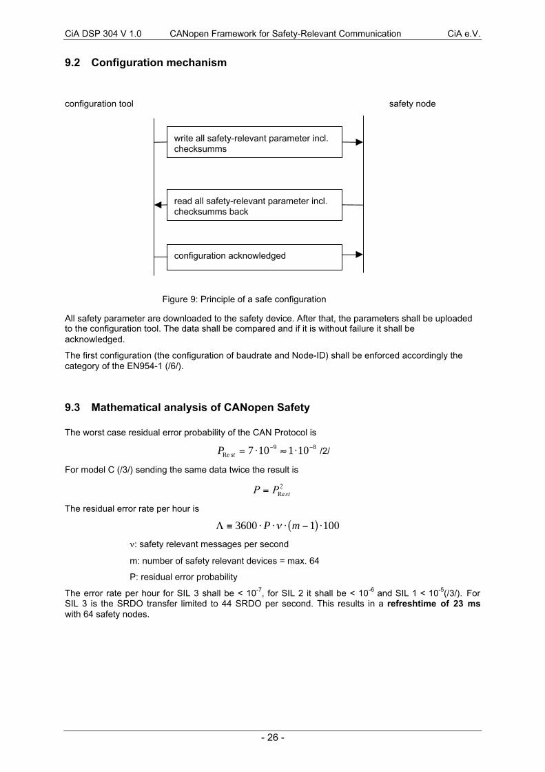
configuration tool safety node
Figure 9: Principle of a safe configuration
All safety parameter are downloaded to the safety device. After that, the parameters shall be uploadedto the configuration tool. The data shall be compared and if it is without failure it shall beacknowledged.
The first configuration (the configuration of baudrate and Node-ID) shall be enforced accordingly thecategory of the EN954-1 (/6/).
9.3 Mathematical analysis of CANopen Safety
The worst case residual error probability of the CAN Protocol is
P stRe = × » ×- -7 10 1 109 8 /2/
For model C (/3/) sending the same data twice the result is
2Re stPP =
The residual error rate per hour is
L º × × × -( ) ×3600 1 100P mn
n: safety relevant messages per second
m: number of safety relevant devices = max. 64
P: residual error probability
The error rate per hour for SIL 3 shall be < 10-7, for SIL 2 it shall be < 10-6 and SIL 1 < 10-5(/3/). ForSIL 3 is the SRDO transfer limited to 44 SRDO per second. This results in a refreshtime of 23 mswith 64 safety nodes.
write all safety-relevant parameter incl.checksumms
read all safety-relevant parameter incl.checksumms back
configuration acknowledged
CiA DSP 304 V 1.0 CANopen Framework for Safety-Relevant Communication CiA e.V.
- 27 -
9.4 Limits and recommendations
· In general the use of remote frames in a safety relevant CANopen network is not recommended.(RTR to SRDOs is not possible anyway).
The use of "node guarding" in a safety-relevant CANopen network is restricted. If required, use insteadthe optional "heart beat" (SRDOs have a implicit guarding mechanism).
In a network with safety-relevant devices it shall be not allowed for non safety-relevant nodes to usethe identifier range of the CANopen Safety.
The implementation of CANopen Safety shall be allowed only in safety devices.
9.5 Rules of implementation
· The first cyclic transmit of an SRDO shall be delayed for 0.5 ms * Node-ID.
· A transmit SRDO shall be built by two different ways from the application.
· A received SRDO shall be compared bit by bit (modulo 2) in the application (data and identifier).
· It shall be guaranteed that the message buffers of the CAN controller are dynamically tested
· The application shall check that the two telegrams of a SRDO are received in chronological order(high priority identifier first). It is important to mark an old received SRDO as invalid.
· The application shall check the parameter in the transition from pre-operational to operational. TheCRC-Entry in the object dictionary shall be equal to the CRC calculation of the safety device andthe Òconfiguration-validÓ Ð flag shall be valid.
Important:
· The rules for implementation of hard-, soft- and firmware in a safety device are defined DIN VVDEÊ0801 or IEC 61508!


