11
| Date post: | 24-Jul-2016 |
| Category: |
Documents |
| Upload: | tom-knoblock |
| View: | 233 times |
| Download: | 2 times |
Project Type
DESCRIPTION
Brite Energy Solutions - Tom Knoblock - 1-844-533-2897 Toll Free - www.Brite-LED-Solutions.com
| | | | |
DATASHEET 11.20.2014Specifications and dimensions subject to change without notice
PUC UNV1- (120-277 VAC) 4100 (Non-Dimmable)
PUC UNV1 - (120-277 VAC) 4100DM (Dimmable)**
PUC UNV2 - (347/480 VAC) 4100DM (Dimmable)***
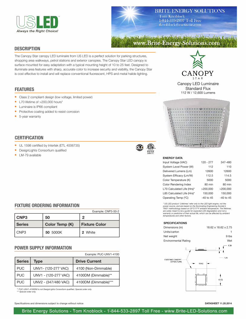
Canopy LED LuminaireStandard Flux
112 W / 12,600 Lumens
ENERGY DATA
347-480
110
12600
114.5
5000
80 min
>200,000
150,000
-40 to 45
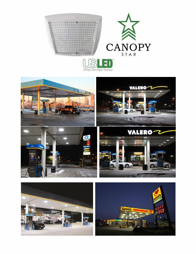
The Canopy Star canopy LED luminaire from US LED is a perfect solution for parking structures, shopping area walkways, petrol stations and exterior canopies. The Canopy Star LED canopy is surface mounted for easy adaptation with a typical mounting height of 10 to 25 feet. Designed to illuminate area features with sharp, accurate color to increase security and visibility, the Canopy Star is cost effective to install and will replace conventional fluorescent, HPS and metal halide lighting.
POWER SUPPLY INFORMATION
FEATURES
Class 2 compliant design (low voltage, limited power)
L70 lifetime of >200,000 hours*
Luminaire is IP66 compliant
Protective coating added to resist corrosion
5-year warranty
l
l
l
l
l
SPECIFICATIONS
Dimensions (in)
Units/carton
Net weight
Environmental Rating
18.62 x 18.62 x 2.75
1
9 lbs
Wet
CERTIFICATIONl
l
l
Input Voltage (VAC)
System Level Power (W)
Delivered Lumens (Lm)
System Efficacy (Lm/W)
Color Temperature (K)
Color Rendering Index
L70 Calculated Life (Hrs)*
L85 Calculated Life (Hrs)*
Operating Temp (ºC)
120 - 277
112
12600
112.5
5000
80 min
>200,000
150,000
-40 to 45
Series Drive CurrentType
Example: PUC-UNV1-4100
UL 1598 certified by Intertek (ETL 4006735)
DesignLights Consortium qualified
LM-79 available
FIXTURE ORDERING INFORMATIONExample: CNP3-50-2
CNP3 50 2
Series
CNP3
Color Temp (K)
50 5000K
* US LED product ‘Lifetimes’ refer only to the LED light engine, not the power source, and are based on the Illuminating Engineering Society’s TM21 methodology based on 25°C/77°F ambient temperature. The lifetimes are solely meant to be a guide for expected LED degradation and not a warranty or predictive of their actual life, which can be affected by ambient temperatures and other factors.
Fixture Color
2 White
** PUC-UNV1-4100DM is not DesignLights Consortium qualified. Special order only.*** Special order only.
Project
Catalog #
Type
DESCRIPTION
US LED | 6807 PORTWEST DR | HOUSTON, TX 77024 | T 866 972 9191 | F 713 972 9393 | [email protected] | www.usled.com
PRELIMINARY DATA SUBJECT TO CHANGEDATASHEET 11.20.2014Specifications and dimensions subject to change without notice
PUC UNV1- (120-277 VAC) 8200 (Non-Dimmable)
PUC UNV1 - (120-277 VAC) 8200DM (Dimmable)**
PUC UNV2 - (347/480 VAC) 8200DM (Dimmable)**
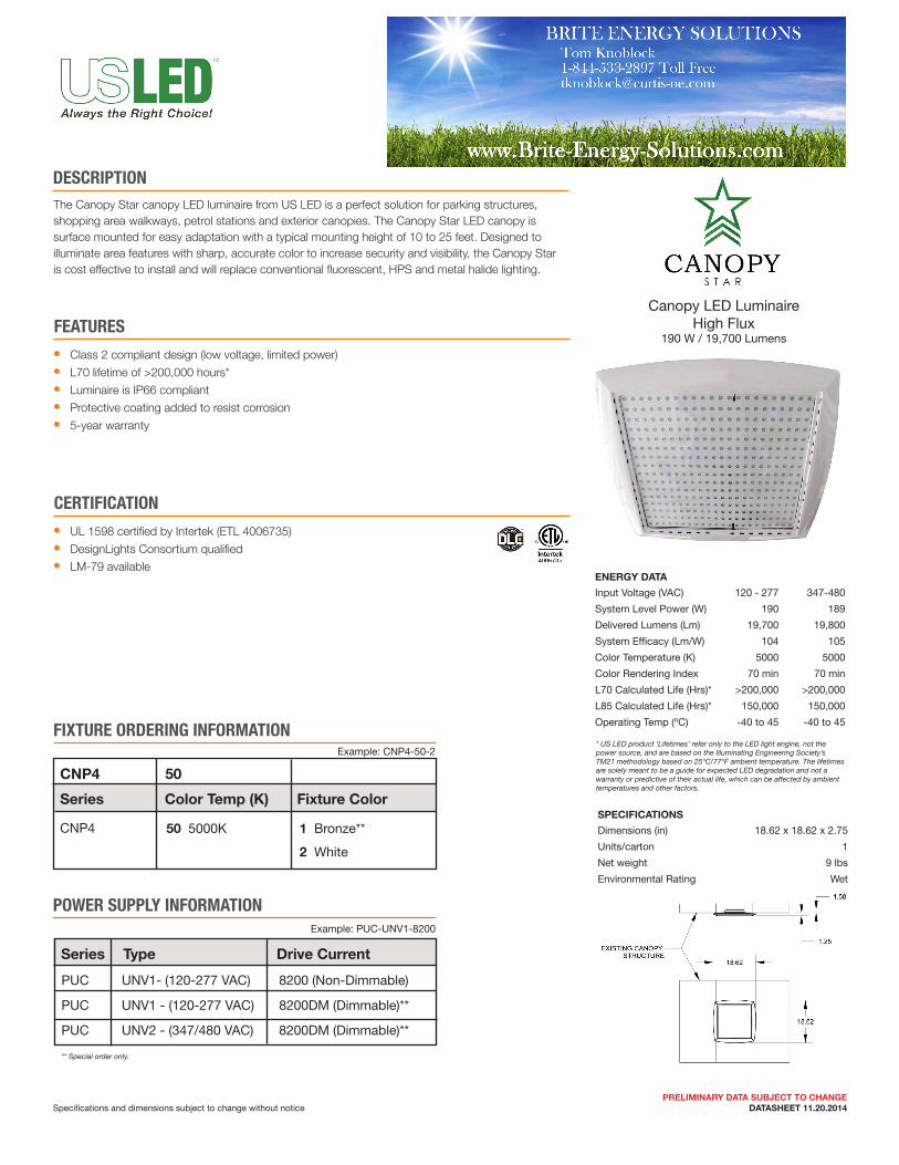
Canopy LED LuminaireHigh Flux
190 W / 19,700 Lumens
ENERGY DATA
347-480
189
19,800
105
5000
70 min
>200,000
150,000
-40 to 45
The Canopy Star canopy LED luminaire from US LED is a perfect solution for parking structures, shopping area walkways, petrol stations and exterior canopies. The Canopy Star LED canopy is surface mounted for easy adaptation with a typical mounting height of 10 to 25 feet. Designed to illuminate area features with sharp, accurate color to increase security and visibility, the Canopy Star is cost effective to install and will replace conventional fluorescent, HPS and metal halide lighting.
POWER SUPPLY INFORMATION
FEATURES
Class 2 compliant design (low voltage, limited power)
L70 lifetime of >200,000 hours*
Luminaire is IP66 compliant
Protective coating added to resist corrosion
5-year warranty
l
l
l
l
l
SPECIFICATIONS
Dimensions (in)
Units/carton
Net weight
Environmental Rating
18.62 x 18.62 x 2.75
1
9 lbs
Wet
CERTIFICATION
Input Voltage (VAC)
System Level Power (W)
Delivered Lumens (Lm)
System Efficacy (Lm/W)
Color Temperature (K)
Color Rendering Index
L70 Calculated Life (Hrs)*
L85 Calculated Life (Hrs)*
Operating Temp (ºC)
120 - 277
190
19,700
104
5000
70 min
>200,000
150,000
-40 to 45
Series Drive CurrentType
Example: PUC-UNV1-8200
FIXTURE ORDERING INFORMATIONExample: CNP4-50-2
CNP4 50
Series
CNP4
Color Temp (K)
50 5000K
* US LED product ‘Lifetimes’ refer only to the LED light engine, not the power source, and are based on the Illuminating Engineering Society’s TM21 methodology based on 25°C/77°F ambient temperature. The lifetimes are solely meant to be a guide for expected LED degradation and not a warranty or predictive of their actual life, which can be affected by ambient temperatures and other factors.
Fixture Color
1 Bronze**
2 White
** Special order only.
l
l
l
UL 1598 certified by Intertek (ETL 4006735)
DesignLights Consortium qualified
LM-79 available
INSTALLATION GUIDECNPx-50
Page 1
Updated 09.26.13
#44-000017
The installation must only be performed by a licensed electrician.
To prevent death, injury or damage to property, this product must be installed in accordance to National Electrical Code (NFPA70) in the US or Canadian Electrical Code (CSA22.1) in Canada.
Disconnect power before installing the product or servicing it.
Wait until fixture has cooled down before installing or servicing the fixture.
MIN. 90°C SUPPLY CONDUCTORS
WARNINGl
l
l
l
l
MODEL NUMBERSThis installation instructions covers the following products:
Power Supplies1. 50W Power Unit: PUC-UNV1-2100 or PUC-UNV2-21002. 75W Power Unit: PUC-UNV1-3000 or PUC-UNV2-30003. 96W Power Unit: PUC-UNV1-3570 or PUC-UNV2-35704. 192W Power Unit: PUC-UNV1-7140 or PUC-UNV2-7140
Luminaires1. CNP1-50 Series Luminaires2. CNP2-50 Series Luminaires
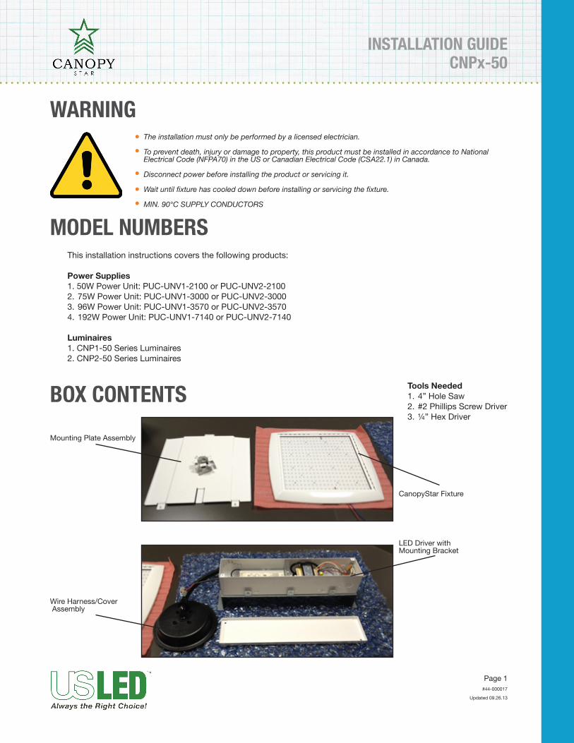
BOX CONTENTS
Mounting Plate Assembly
Wire Harness/Cover Assembly
CanopyStar Fixture
LED Driver withMounting Bracket
Tools Needed1. 4” Hole Saw2. #2 Phillips Screw Driver3. ¼” Hex Driver
Page 2
Updated 09.26.13
CNPx-50INSTALLATION GUIDE
#44-000017
1. Using4”holesaw,cutholeincanopywherefixtureistobemounted.Holelocationneedstobecenteredbe-tweencanopyribstoallowwireharness/coverassemblytofit.
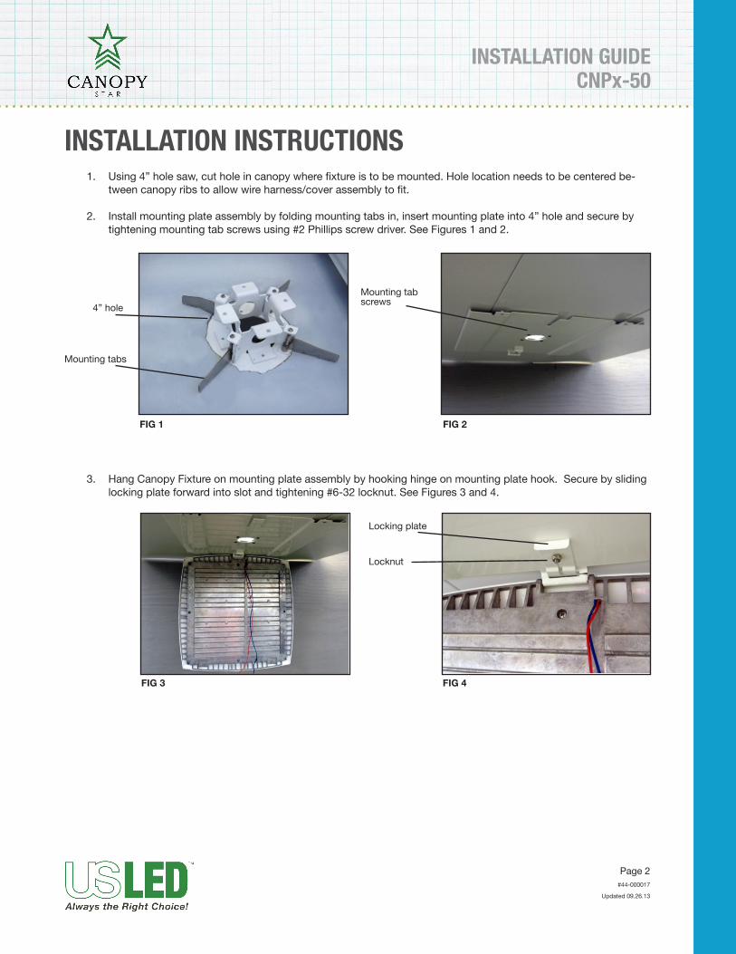
2. Install mounting plate assembly by folding mounting tabs in, insert mounting plate into 4” hole and secure by tightening mounting tab screws using #2 Phillips screw driver. See Figures 1 and 2.
INSTALLATION INSTRUCTIONS
4” hole
Mounting tabs
FIG 1 FIG 2
Mounting tabscrews
FIG 3 FIG 4
3. Hang Canopy Fixture on mounting plate assembly by hooking hinge on mounting plate hook. Secure by sliding locking plate forward into slot and tightening #6-32 locknut. See Figures 3 and 4.
Locking plate
Locknut
INSTALLATION GUIDECNPx-50
Page 3
US LED
Updated 09.26.13
#44-000017
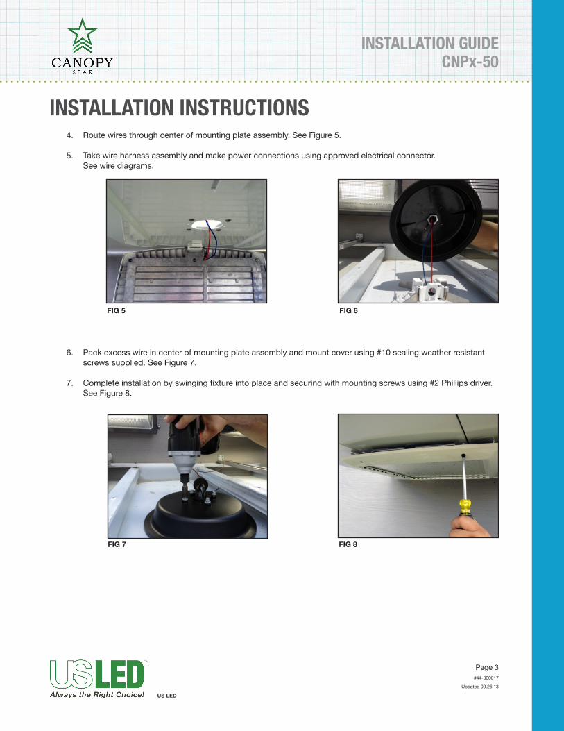
4. Route wires through center of mounting plate assembly. See Figure 5.
5. Take wire harness assembly and make power connections using approved electrical connector. See wire diagrams.
INSTALLATION INSTRUCTIONS
FIG 5 FIG 6
FIG 7 FIG 8
6. Pack excess wire in center of mounting plate assembly and mount cover using #10 sealing weather resistant screws supplied. See Figure 7.
7. Completeinstallationbyswingingfixtureintoplaceandsecuringwithmountingscrewsusing#2Phillipsdriver.See Figure 8.
Page 4
US LED
Updated 09.26.13
CNPx-50INSTALLATION GUIDE
#44-000017
1. Turn off main power.
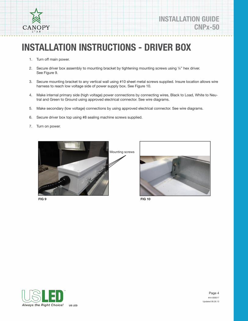
2. Secure driver box assembly to mounting bracket by tightening mounting screws using ¼” hex driver. See Figure 9.
3. Secure mounting bracket to any vertical wall using #10 sheet metal screws supplied. Insure location allows wire harness to reach low voltage side of power supply box. See Figure 10.
4. Make internal primary side (high voltage) power connections by connecting wires, Black to Load, White to Neu-tral and Green to Ground using approved electrical connector. See wire diagrams.
5. Make secondary (low voltage) connections by using approved electrical connector. See wire diagrams.
6. Secure driver box top using #8 sealing machine screws supplied.
7. Turn on power.
INSTALLATION INSTRUCTIONS - DRIVER BOX
FIG 9 FIG 10
Mounting screws
INSTALLATION GUIDECNPx-50
Page 5
US LED
Updated 09.26.13
#44-000017
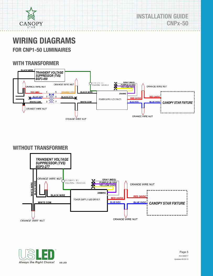
WIRING DIAGRAMS
WITH TRANSFORMER
WITHOUT TRANSFORMER
FOR CNP1-50 LUMINAIRES
Page 6
US LED
Updated 09.26.13
CNPx-50INSTALLATION GUIDE
#44-000017
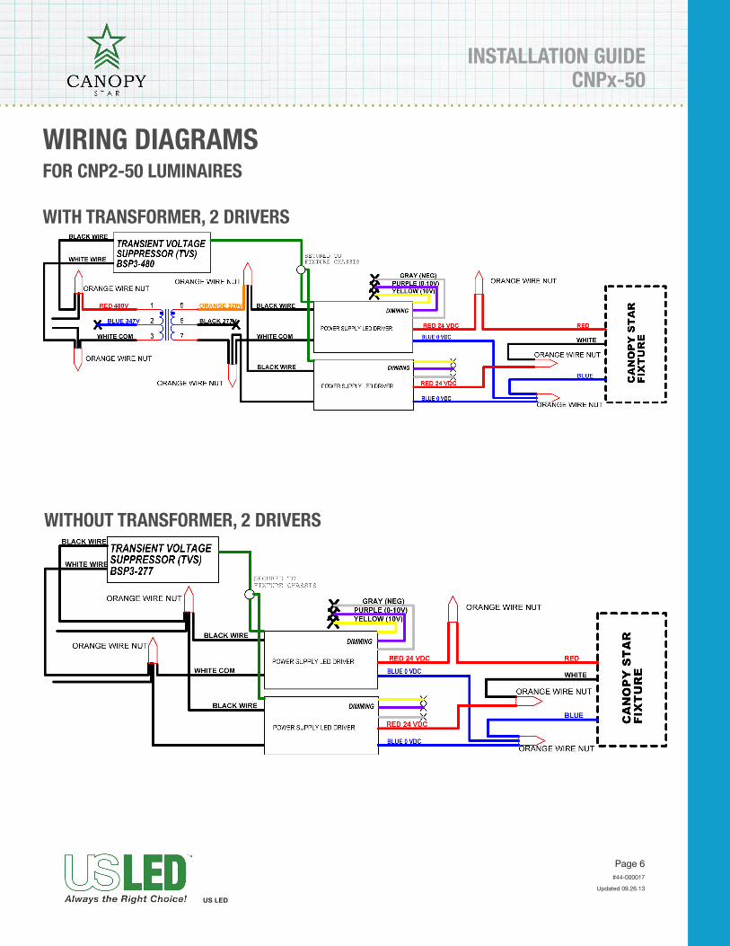
WITHOUT TRANSFORMER, 2 DRIVERS
WIRING DIAGRAMS
WITH TRANSFORMER, 2 DRIVERS
FOR CNP2-50 LUMINAIRES
SURFACE MOUNT KIT INSTALLATION GUIDECNPx-50
Page 1
Updated 03.28.14
The installation must only be performed by a licensed electrician.
To prevent death, injury or damage to property, this product must be installed in accordance to National Electrical Code (NFPA70) in the US or Canadian Electrical Code (CSA22.1) in Canada.
Disconnect power before installing the product or servicing it.
Wait until fixture has cooled down before installing or servicing the fixture.
MIN. 90°C SUPPLY CONDUCTORS
WARNINGl
l
l
l
l
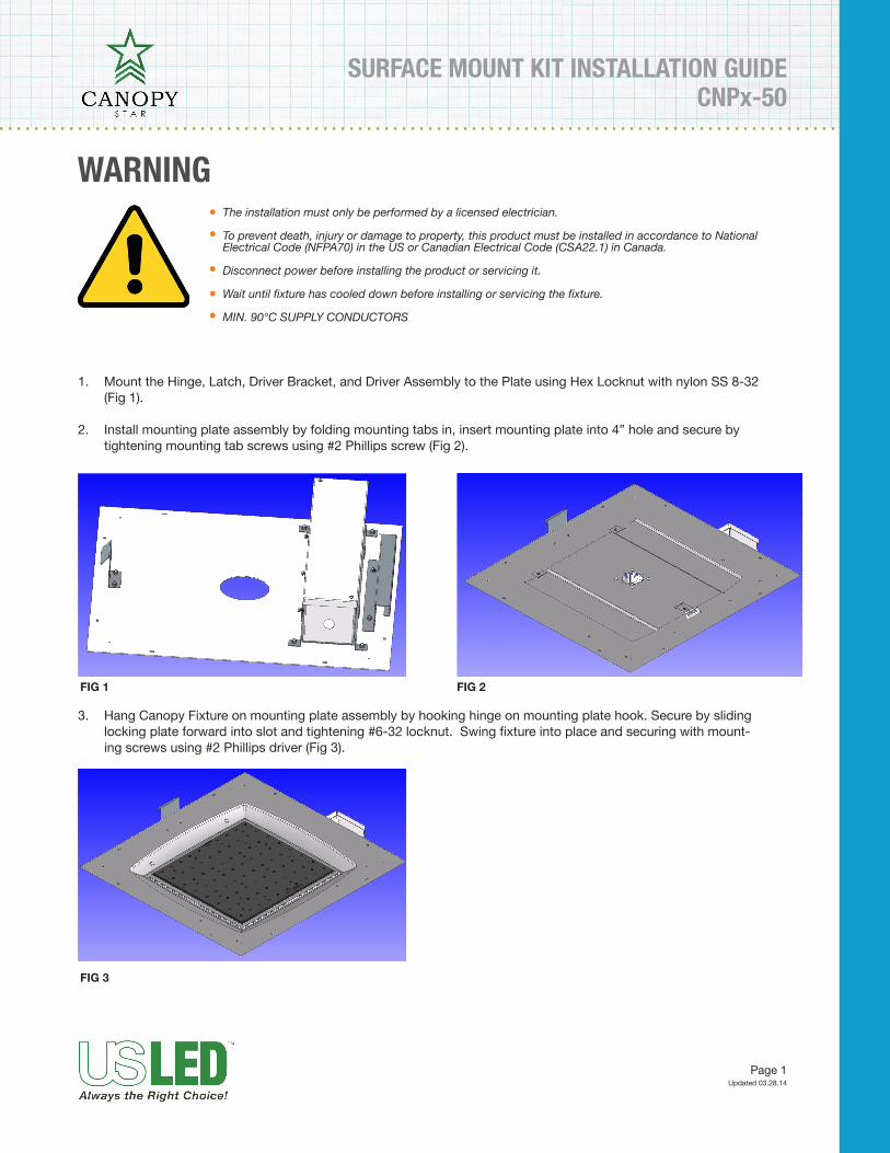
1. Mount the Hinge, Latch, Driver Bracket, and Driver Assembly to the Plate using Hex Locknut with nylon SS 8-32 (Fig 1).
2. Install mounting plate assembly by folding mounting tabs in, insert mounting plate into 4” hole and secure by tightening mounting tab screws using #2 Phillips screw (Fig 2).
FIG 1 FIG 2
FIG 3
3. Hang Canopy Fixture on mounting plate assembly by hooking hinge on mounting plate hook. Secure by sliding locking plate forward into slot and tightening #6-32 locknut. Swing fixture into place and securing with mount-ing screws using #2 Phillips driver (Fig 3).
Page 2
Updated 03.28.14
CNPx-50SURFACE MOUNT KIT INSTALLATION GUIDE
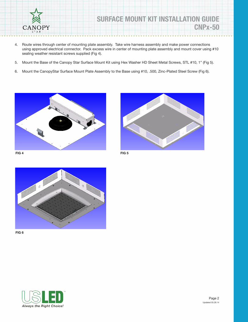
4. Route wires through center of mounting plate assembly. Take wire harness assembly and make power connections using approved electrical connector. Pack excess wire in center of mounting plate assembly and mount cover using #10 sealing weather resistant screws supplied (Fig 4).
5. Mount the Base of the Canopy Star Surface Mount Kit using Hex Washer HD Sheet Metal Screws, STL #10, 1” (Fig 5).
6. Mount the CanopyStar Surface Mount Plate Assembly to the Base using #10, .500, Zinc-Plated Steel Screw (Fig 6).
FIG 4 FIG 5
FIG 6


