Managed by Triad National Security, LLC for the U.S. Department of Energy’s NNSA Capacitive Discharge Resistance Welding of 14YWT and Other Alloys LA-UR-# LA-UR-20-XXXXX UNCLASSIFIED C.R. Lear 1 , B.P. Eftink 1 , L. Lindamood 2 , T.E. Steckley 1 , M.M. Schneider 1 , J. Gould 2 , T.J. Lienert 3 , S.A. Maloy 1 1 Los Alamos National Laboratory, Los Alamos, NM 87545 2 EWI, Columbus, OH 43221 3 T.J. Lienert Consulting, LLC, Los Alamos, NM 87544
Transcript
Managed by Triad National Security, LLC for the U.S. Department of Energy’s NNSA
Capacitive Discharge Resistance Welding
of 14YWT and Other Alloys
LA-UR-#
LA-UR-20-XXXXX
UNCLASSIFIED
C.R. Lear1, B.P. Eftink1, L. Lindamood2, T.E. Steckley1,
M.M. Schneider1, J. Gould2, T.J. Lienert3, S.A. Maloy1
1 Los Alamos National Laboratory, Los Alamos, NM 875452 EWI, Columbus, OH 432213 T.J. Lienert Consulting, LLC, Los Alamos, NM 87544
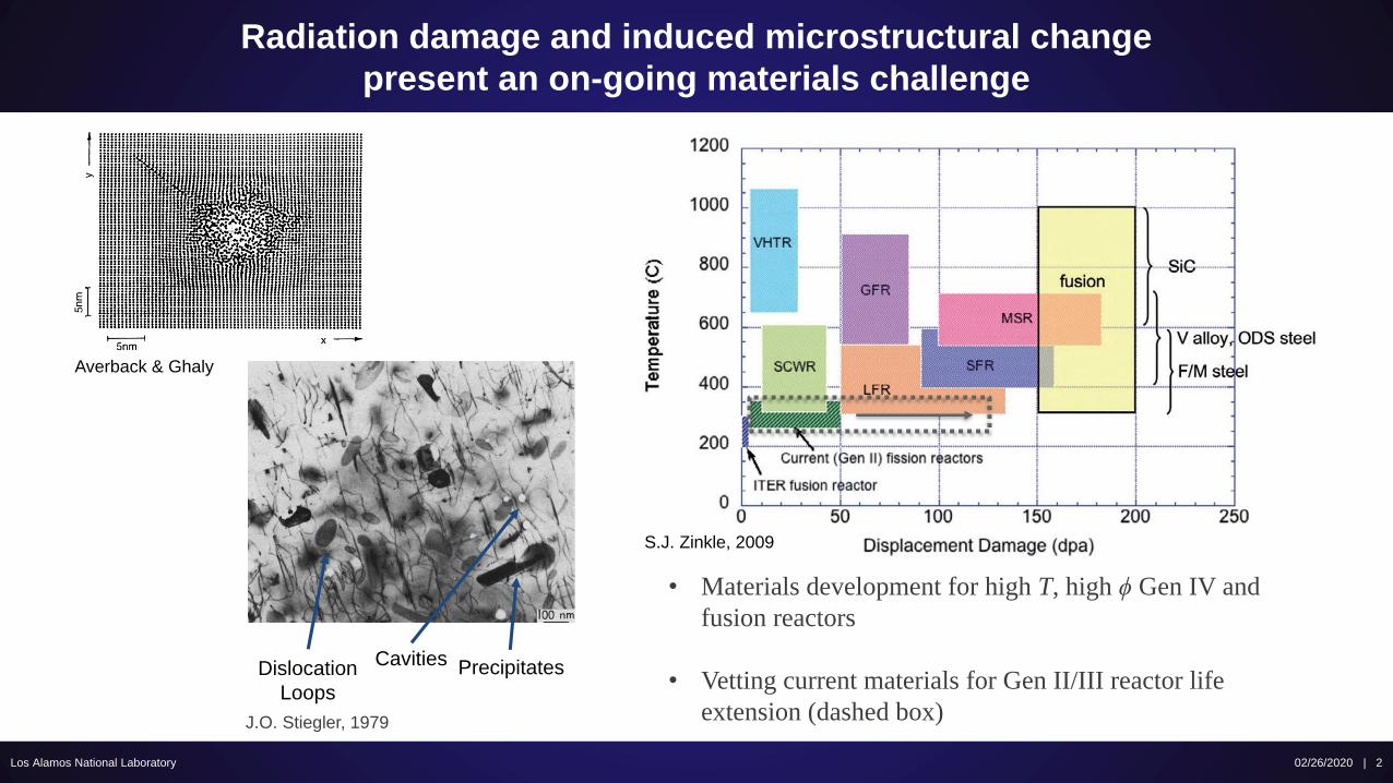
Radiation damage and induced microstructural change
present an on-going materials challenge
02/26/2020 | 2Los Alamos National Laboratory
J.O. Stiegler, 1979
Averback & Ghaly
Dislocation
Loops
PrecipitatesCavities
• Materials development for high T, high ϕ Gen IV and
fusion reactors
• Vetting current materials for Gen II/III reactor life
extension (dashed box)
S.J. Zinkle, 2009
Nanostructured materials trap defects and gasses,
limiting evolution and minimizing deterioration
Los Alamos National Laboratory
G.R. Odette, 2008
• Nanostructured ferritic alloys (NFA) are
formed by mechanical alloying for fine grains
and high densities of nanoscale features
• Resistance to creep and coarsening at
high temperature
• Voids/bubbles kept small and off grain
boundaries via abundant nucleation
• Oxide dispersion strengthened (ODS) alloys
are promising NFAs, as Y, Al, and Ti based
nanoparticles are fully incoherent and very
stable with irradiation
• With proper chemistry, NFA ODS materials
have also shown improved high temperature
oxidation resistance vs. conventional claddings
02/26/2020 | 3
Los Alamos National Laboratory
• Conventional fusion techniques degrade
microstructure via heat input and local melting
• Growth of nanoscale grains
• Coarsening, agglomeration, or redistribution
of ODS particles in molten regions
• Has driven development of solid state
welding (SSW) techniques
• Friction stir welding (FSW) is one of several SSW
techniques in use today
• Friction heating softens material at the joint
without melting, allowing for physical mixing
• Has been used for 20 years for steels, with
some success on NFA’s
• Leaves a hole when the tool is withdrawn and
is not an option for small or complex parts
NFA-ODS microstructures and dispersoids require
advanced welding techniques
02/26/2020 | 4
Z. Feng & W. Ren, 2006
Los Alamos National Laboratory
NFA-ODS microstructures and dispersoids require
advanced welding techniques
• Pressure resistance welding (PRW) is flexible
alternative SSW for cladding
• Resistive heating softens the point of
contact between parts, while mechanical
pressure forces material to flow and bond
• Commonly uses a “projection”, or reduced
contact, to focus heating and deformation.
This collapses, driving aside surface oxides
and minimizing affected material
• Capacitive discharge resistance welding (CDRW)
is a modification of PRW
• A capacitor bank to guarantees fast
discharge of high current
• Rapid thermal cycles, 2-5x faster than most
PRW, limit microstructural evolution and
excess heating
02/26/2020 | 5
Plug
Tube
Plug
Tube
Plug
Tube
J. Gan, 2018
60º Chamfer
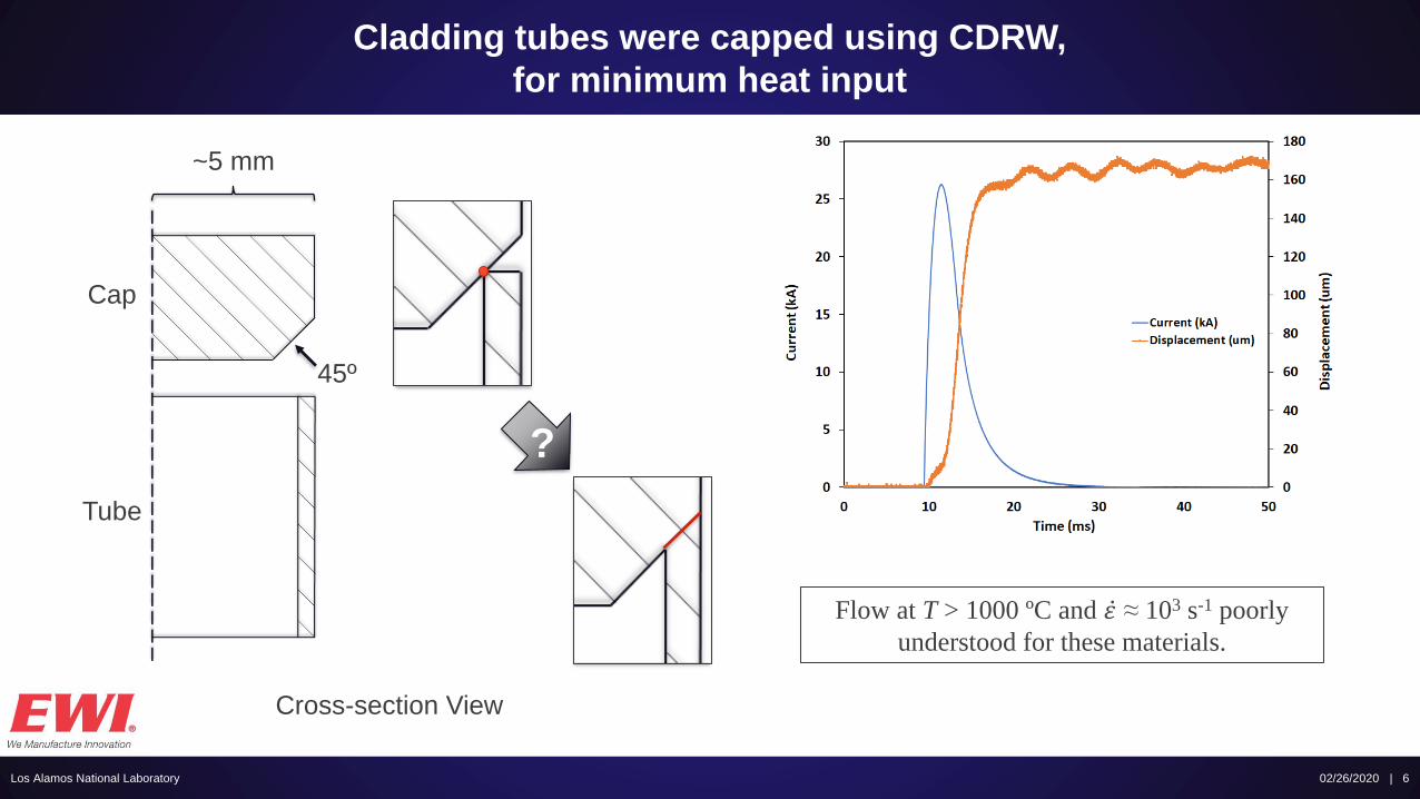
Cladding tubes were capped using CDRW,
for minimum heat input
Los Alamos National Laboratory 02/26/2020 | 6
Cross-section View
Cap
Tube
~5 mm
45º
?
Flow at T > 1000 ºC and ሶ𝜀 ≈ 103 s-1 poorly
understood for these materials.
Los Alamos National Laboratory
Backflow
Into Tube
Resolidification
& Coarsening
Incomplete
Sealing
Tube
B126Y
Cap
Kanthal
Rapid screening using optical microscopy;
detailed characterization using electron microscopy
Dynamic
Recrystallization
at Weld Line
MA956
ODS Particles
Tube
B126Y
Cap
Kanthal
02/26/2020 | 7
(left) Grain orientations
mapped using EBSD
(right) Dispersoids imaged
using HAADF STEM
14YWT – 14YWT
(ODS – ODS)
Focus on two groups of welds
Los Alamos National Laboratory
B126Y – MA956
(FeCrAl – ODS)
Typical CDRW Structure?
Parameter Influence?
Radiation Stability?
02/26/2020 | 8
Los Alamos National Laboratory
Cap
MA956
Tube
B126Y
CI > 0.1
Microstructural effects of CDRW were extremely localized
02/26/2020 | 9
Los Alamos National Laboratory
Base
Material
Mechanically
Affected
~100 μm
Recrystallized
~50 μm
CI > 0.1
Microstructural effects of CDRW were extremely localized
Cap
MA956
Tube
B126Y
02/26/2020 | 10
Los Alamos National Laboratory
Base
Material
Mechanically
Affected
~100 μm
Recrystallized
~50 μm
Note the difference between
“hard” and “soft” components.
CI > 0.1
Microstructural effects of CDRW were extremely localized
Cap
MA956
Tube
B126Y
02/26/2020 | 11
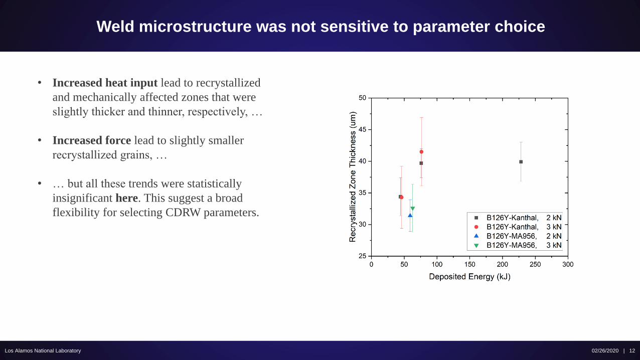
Weld microstructure was not sensitive to parameter choice
Los Alamos National Laboratory 02/26/2020 | 12
• Increased heat input lead to recrystallized
and mechanically affected zones that were
slightly thicker and thinner, respectively, …
• Increased force lead to slightly smaller
recrystallized grains, …
• … but all these trends were statistically
insignificant here. This suggest a broad
flexibility for selecting CDRW parameters.
Los Alamos National Laboratory 02/26/2020 | 13
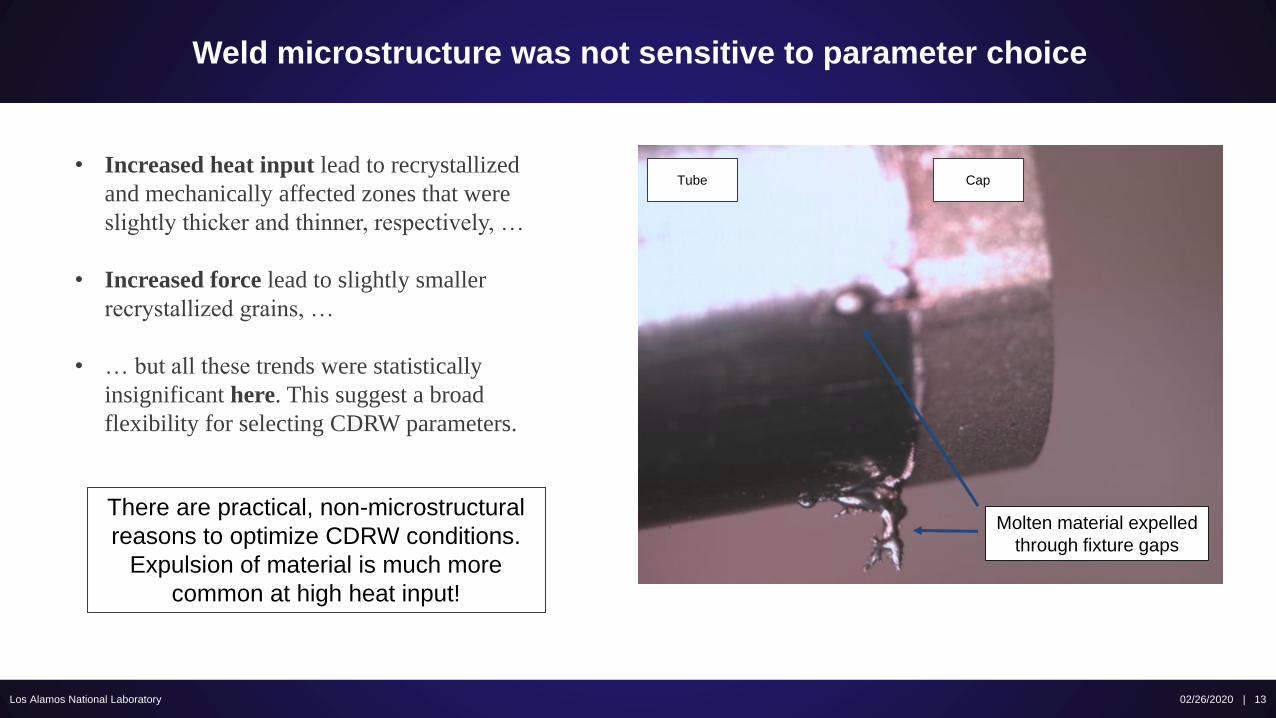
• Increased heat input lead to recrystallized
and mechanically affected zones that were
slightly thicker and thinner, respectively, …
• Increased force lead to slightly smaller
recrystallized grains, …
• … but all these trends were statistically
insignificant here. This suggest a broad
flexibility for selecting CDRW parameters.
Tube Cap
Molten material expelled
through fixture gaps
There are practical, non-microstructural
reasons to optimize CDRW conditions.
Expulsion of material is much more
common at high heat input!
Weld microstructure was not sensitive to parameter choice
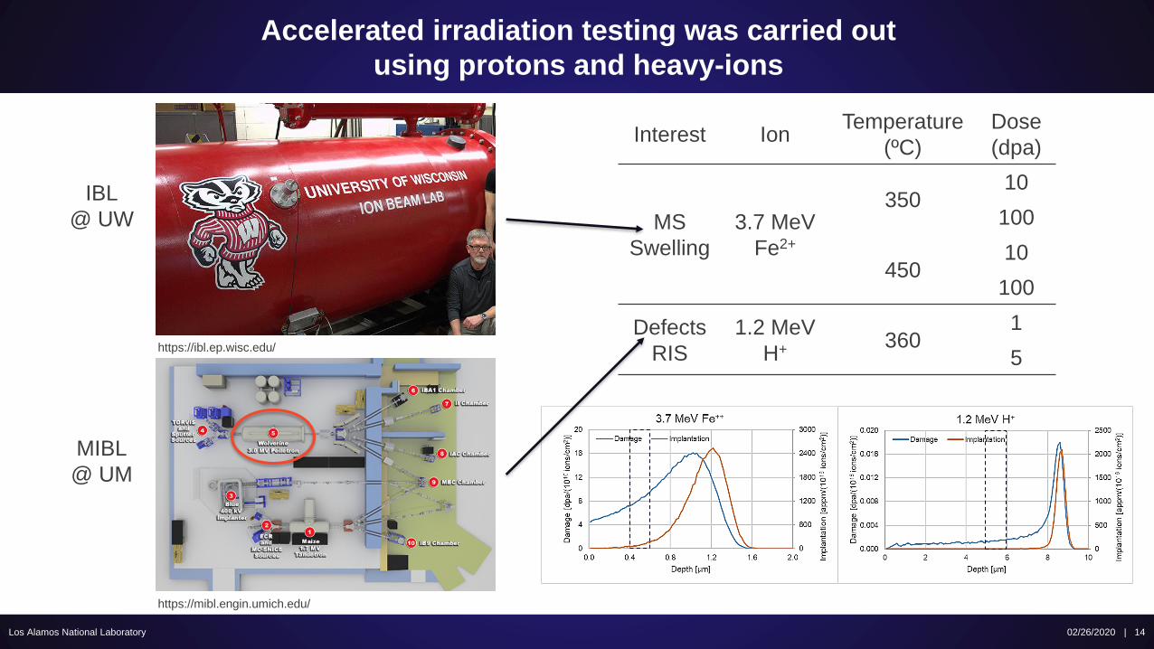
Accelerated irradiation testing was carried out
using protons and heavy-ions
Los Alamos National Laboratory
IBL
@ UW
MIBL
@ UM
https://mibl.engin.umich.edu/
https://ibl.ep.wisc.edu/
Interest IonTemperature
(ºC)
Dose
(dpa)
MS
Swelling
3.7 MeV
Fe2+
35010
100
45010
100
Defects
RIS
1.2 MeV
H+ 3601
5
02/26/2020 | 14
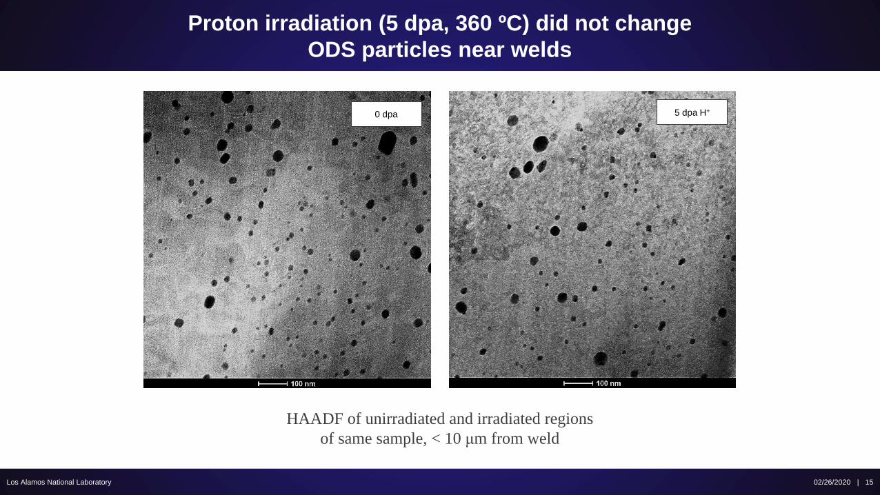
Proton irradiation (5 dpa, 360 ºC) did not change
ODS particles near welds
Los Alamos National Laboratory
HAADF of unirradiated and irradiated regions
of same sample, < 10 μm from weld
5 dpa H+0 dpa
02/26/2020 | 15
Proton irradiation (5 dpa, 360 ºC) did not change
ODS particles near welds
Los Alamos National Laboratory
HAADF of unirradiated and irradiated regions
of same sample, < 10 μm from weld
5 dpa H+0 dpa
02/26/2020 | 16
14YWT – 14YWT
(ODS – ODS)
Impact of Strength?
Dispersoid Evolution?
Focus on two groups of welds
Los Alamos National Laboratory
B126Y – MA956
(FeCrAl – ODS)
02/26/2020 | 17
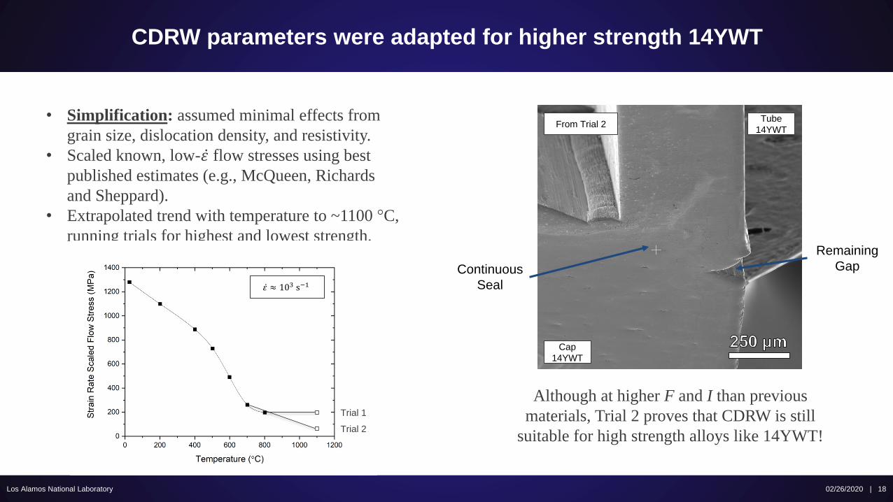
CDRW parameters were adapted for higher strength 14YWT
Los Alamos National Laboratory
Although at higher F and I than previous
materials, Trial 2 proves that CDRW is still
suitable for high strength alloys like 14YWT!
02/26/2020 | 18
• Simplification: assumed minimal effects from
grain size, dislocation density, and resistivity.
• Scaled known, low- ሶ𝜀 flow stresses using best
published estimates (e.g., McQueen, Richards
and Sheppard).
• Extrapolated trend with temperature to ~1100 °C,
running trials for highest and lowest strength.
Tube
14YWT
Cap
14YWT
From Trial 2
Remaining
GapContinuous
Seal
Trial 1
Trial 2
ሶ𝜀 ≈ 103 s−1
Small-scale microstructure unchanged by CDRW
Los Alamos National Laboratory 02/26/2020 | 19
Pre-existing
Large Grains
“Under-quenched”
Material
Warping
of Tube
“Texture”
Pre-existing
Large Grains
Tube
14YWT
Cap
14YWT
Dispersoids remained uniformly distributed after CDRW
Los Alamos National Laboratory 02/26/2020 | 20
Weld ~5 μm~5 μm~10 μm
The smallest dispersoids remain after CDRW
Los Alamos National Laboratory 02/26/2020 | 21
~10 μm from Weld
The smallest dispersoids remain after CDRW
Los Alamos National Laboratory 02/26/2020 | 22
~10 μm from Weld
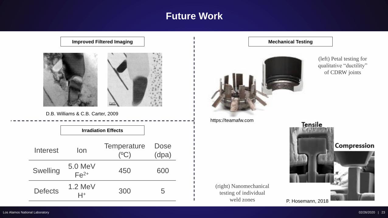
Future Work
Los Alamos National Laboratory 02/26/2020 | 23
Interest IonTemperature
(ºC)
Dose
(dpa)
Swelling5.0 MeV
Fe2+ 450 600
Defects1.2 MeV
H+ 300 5
D.B. Williams & C.B. Carter, 2009
Improved Filtered Imaging
Irradiation Effects
Mechanical Testing
P. Hosemann, 2018
https://teamafw.com
(left) Petal testing for
qualitative “ductility”
of CDRW joints
(right) Nanomechanical
testing of individual
weld zones
Conclusions
Los Alamos National Laboratory 02/26/2020 | 24
• CDRW was used to join similar and differing ferritic alloys, with a focus on ODS weldability. Joint quality varied, but solid
bonds were produced for even considerably stronger alloys like 14YWT.
• CDRW joints showed considerably thinner – or absent – weld zones than more conventional techniques, suggesting that
weld performance (e.g., strength, resistance to degradation) will be favorable. The extent of these zones was minimally
effected by parameter choice, though material expulsion at high heat input could create practical issues in industry.
• CDRW of MA956 and 14YWT components did not redistribute dispersed particles inhomogeneously in areas nearest the
joint, and the smallest particles in 14YWT (~2 nm diameter) were preserved. Future work in this line will focus on improved
microscopy of these dispersoids.
• CDRW joined MA956 showed no significant changes in dispersed particles after 5 dpa proton irradiation, but analysis of
heavy-ion irradiated samples is still ongoing. Future work in this line will focus on irradiation of newly made 14YWT welds
to understand hardening and high-dose swelling effects.
• Work will begin soon on mechanical testing of old and new CDRW joints, with nanomechanical testing used to probe
individual weld zones. Petal testing will provide a further qualitative benchmark of weld “ductility”.
This work was supported by the U.S. Department of Energy, Office of Nuclear Energy under DOE Idaho
Operations Office Contract DE-AC07- 051D14517 as part of a Nuclear Science User Facilities experiment.