32
Capacitor-based DC Uninterruptible Power Supplies Catalog Numbers 1606-XLSCAP24-6, -XLSCAP24-12 Reference Manual Original Instructions

Capacitor-based DC Uninterruptible Power SuppliesCatalog Numbers 1606-XLSCAP24-6, -XLSCAP24-12
Reference ManualOriginal Instructions

Important User Information
Read this document and the documents listed in the additional resources section about installation, configuration, and operation of this equipment before you install, configure, operate, or maintain this product. Users are required to familiarize themselves with installation and wiring instructions in addition to requirements of all applicable codes, laws, and standards.
Activities including installation, adjustments, putting into service, use, assembly, disassembly, and maintenance are required to be carried out by suitably trained personnel in accordance with applicable code of practice.
If this equipment is used in a manner not specified by the manufacturer, the protection provided by the equipment may be impaired.
In no event will Rockwell Automation, Inc. be responsible or liable for indirect or consequential damages resulting from the use or application of this equipment.
The examples and diagrams in this manual are included solely for illustrative purposes. Because of the many variables and requirements associated with any particular installation, Rockwell Automation, Inc. cannot assume responsibility or liability for actual use based on the examples and diagrams.
No patent liability is assumed by Rockwell Automation, Inc. with respect to use of information, circuits, equipment, or software described in this manual.
Reproduction of the contents of this manual, in whole or in part, without written permission of Rockwell Automation, Inc., is prohibited
Throughout this manual, when necessary, we use notes to make you aware of safety considerations.
Labels may also be on or inside the equipment to provide specific precautions.
WARNING: Identifies information about practices or circumstances that can cause an explosion in a hazardous environment, which may lead to personal injury or death, property damage, or economic loss.
ATTENTION: Identifies information about practices or circumstances that can lead to personal injury or death, property damage, or economic loss. Attentions help you identify a hazard, avoid a hazard, and recognize the consequence.
IMPORTANT Identifies information that is critical for successful application and understanding of the product.
SHOCK HAZARD: Labels may be on or inside the equipment, for example, a drive or motor, to alert people that dangerous voltage may be present.
BURN HAZARD: Labels may be on or inside the equipment, for example, a drive or motor, to alert people that surfaces may reach dangerous temperatures.
ARC FLASH HAZARD: Labels may be on or inside the equipment, for example, a motor control center, to alert people to potential Arc Flash. Arc Flash will cause severe injury or death. Wear proper Personal Protective Equipment (PPE). Follow ALL Regulatory requirements for safe work practices and for Personal Protective Equipment (PPE).
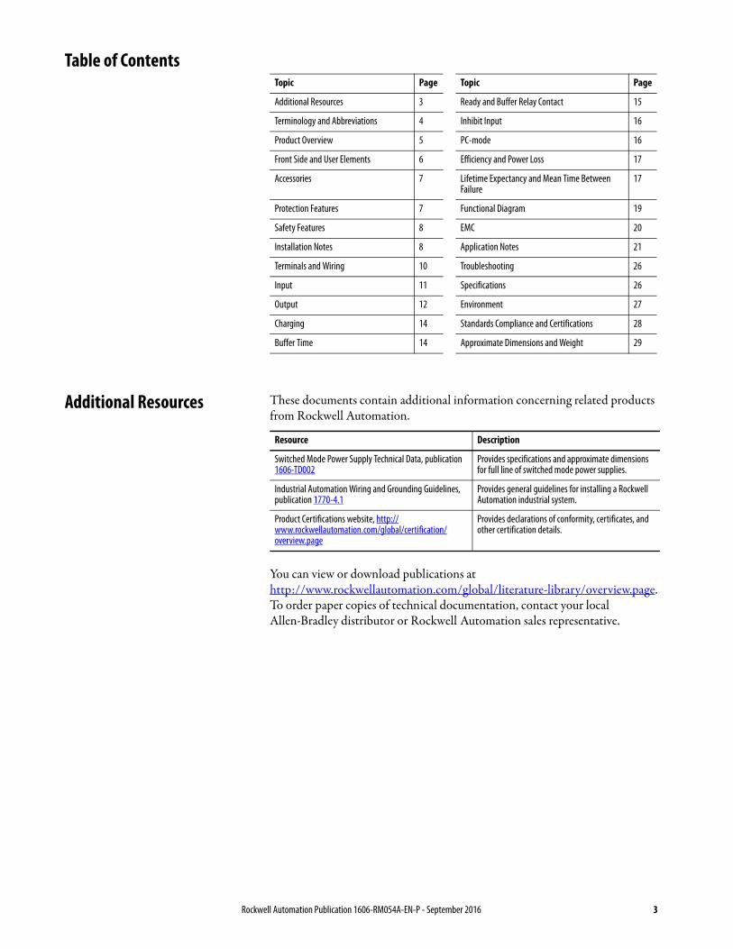
Table of Contents
Additional Resources These documents contain additional information concerning related products from Rockwell Automation.
You can view or download publications at http://www.rockwellautomation.com/global/literature-library/overview.page. To order paper copies of technical documentation, contact your local Allen-Bradley distributor or Rockwell Automation sales representative.
Topic Page Topic Page
Additional Resources 3 Ready and Buffer Relay Contact 15
Terminology and Abbreviations 4 Inhibit Input 16
Product Overview 5 PC-mode 16
Front Side and User Elements 6 Efficiency and Power Loss 17
Accessories 7 Lifetime Expectancy and Mean Time Between Failure
17
Protection Features 7 Functional Diagram 19
Safety Features 8 EMC 20
Installation Notes 8 Application Notes 21
Terminals and Wiring 10 Troubleshooting 26
Input 11 Specifications 26
Output 12 Environment 27
Charging 14 Standards Compliance and Certifications 28
Buffer Time 14 Approximate Dimensions and Weight 29
Resource Description
Switched Mode Power Supply Technical Data, publication 1606-TD002
Provides specifications and approximate dimensions for full line of switched mode power supplies.
Industrial Automation Wiring and Grounding Guidelines, publication 1770-4.1
Provides general guidelines for installing a Rockwell Automation industrial system.
Product Certifications website, http://www.rockwellautomation.com/global/certification/overview.page
Provides declarations of conformity, certificates, and other certification details.
Rockwell Automation Publication 1606-RM054A-EN-P - September 2016 3

Capacitor-based DC UPS Power Supplies
Terminology and Abbreviations Term Definition
Normal mode Describes a condition where the capacitor is charged, the input voltage is in range, and the output is loaded within the allowed limits.
Buffer mode Describes a condition where the input voltage is below the transfer threshold level, the unit is running on capacitor (buffering) and the output is loaded within the allowed limits.
Charging mode Describes a condition where the capacitor is being charged, the input voltage is in range and the output is loaded within the allowed limits.
Inhibit mode Describes a condition where buffering is disabled on purpose (service actions)
AC 24V A figure displayed with the AC or DC before the value represents a nominal voltage with standard tolerances included. For example, DC 12V describes a 12V battery disregarding whether it is full (13.7V) or flat (10V)
24V AC A figure with the unit (V AC) at the end is a momentary figure without any additional tolerances included.
DC-UPS Direct Current- Uninterruptible Power Supplies
ELDC Electrochemical Double Layer Capacitors
EMC Electromagnetic Compatibility
VRLA Valve-regulated Lead-acid
PELV Protected Extra-low Voltage
SELV Separated Extra-low Voltage
4 Rockwell Automation Publication 1606-RM054A-EN-P - September 2016
Capacitor-based DC UPS Power Supplies
Product Overview Bulletin 1606 DC- Uninterruptible Power Supplies (DC-UPSs) use electrochemical double-layer capacitors (EDLC), commonly known as ultracapacitors or supercapacitors, that are installed inside. They can bridge power failures or voltage fluctuation and supply voltage to the DC 24V bus for a certain period, which allows for a controlled shut-down of the system. Expensive downtimes, long restart cycles, and loss of data can be avoided.
The power supply provides sufficient voltages, the DC-UPS stores energy in the capacitors. If there is a mains voltage fault, this energy is released to the DC bus in a regulated process.
The DC-UPSs require no maintenance and have a similar lifetime expectancy as standard power supplies. No regular replacement of the capacitors is necessary as is required for battery-based DC-UPS systems. The wide temperature range makes the unit suitable for many applications.
Two versions of the DC-UPSs are available and differ by the size of the installed capacitor.
• Built-in capacitors as energy source, EDLC • Wide temperature range: -40…+60 °C (-40…+140 °F)• Typically >10 years operational lifetime expectancy• Regulated output voltage in Buffer mode• No ventilated cabinets required, no generation of hydrogen as valve-
regulated lead-acid (VRLA) batteries do• Active balancing for longest life and buffer times• Short charging time, unit is rapidly back in Ready mode• Output is decoupled from the input to separate load• Circuits into buffered and non-buffered sections• Supports PC-mode function• One year warranty
Rockwell Automation Publication 1606-RM054A-EN-P - September 2016 5
Capacitor-based DC UPS Power Supplies
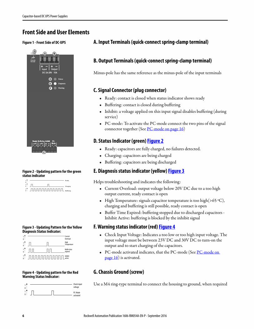
Front Side and User ElementsFigure 1 - Front Side of DC-UPS A. Input Terminals (quick-connect spring-clamp terminal)
B. Output Terminals (quick-connect spring-clamp terminal)
Minus-pole has the same reference as the minus-pole of the input terminals
C. Signal Connector (plug connector) • Ready: contact is closed when status indicator shows ready• Buffering: contact is closed during buffering • Inhibit: a voltage applied on this input signal disables buffering (during
service)• PC-mode: To activate the PC-mode connect the two pins of the signal
connector together (See PC-mode on page 16)
D. Status Indicator (green) Figure 2• Ready: capacitors are fully charged, no failures detected.• Charging: capacitors are being charged• Buffering: capacitors are being discharged
Figure 2 - Updating pattern for the green status indicator
E. Diagnosis status indicator (yellow) Figure 3
Helps troubleshooting and indicates the following:• Current Overload: output voltage below 20V DC due to a too high
output current, ready contact is open • High Temperature: signals capacitor temperature is too high(>65 ºC),
charging and buffering is still possible, ready contact is open • Buffer Time Expired: buffering stopped due to discharged capacitors -
Inhibit Active: buffering is blocked by the inhibit signal
Figure 3 - Updating Pattern for the Yellow Diagnosis Status Indicator:
F. Warning status indicator (red) Figure 4• Check Input Voltage: Indicates a too low or too high input voltage. The
input voltage must be between 23V DC and 30V DC to turn-on the output and to start charging of the capacitors.
• PC-mode activated indicates, that the PC-mode (See PC-mode on page 16) is activated.
Figure 4 - Updating pattern for the Red Warning Status Indicator:
G. Chassis Ground (screw)
Use a M4 ring-type terminal to connect the housing to ground, when required
10
Ready
10 Charging
10 Buffering
10
CurrentOverload
10
HighTemperature
10
Buffer timeexpired
10
Inhibitactive
Check inputvoltage
1010
PC-Modeactivated
6 Rockwell Automation Publication 1606-RM054A-EN-P - September 2016
Capacitor-based DC UPS Power Supplies
Rockwell Automation Publication 1606-RM054A-EN-P - September 2016 7
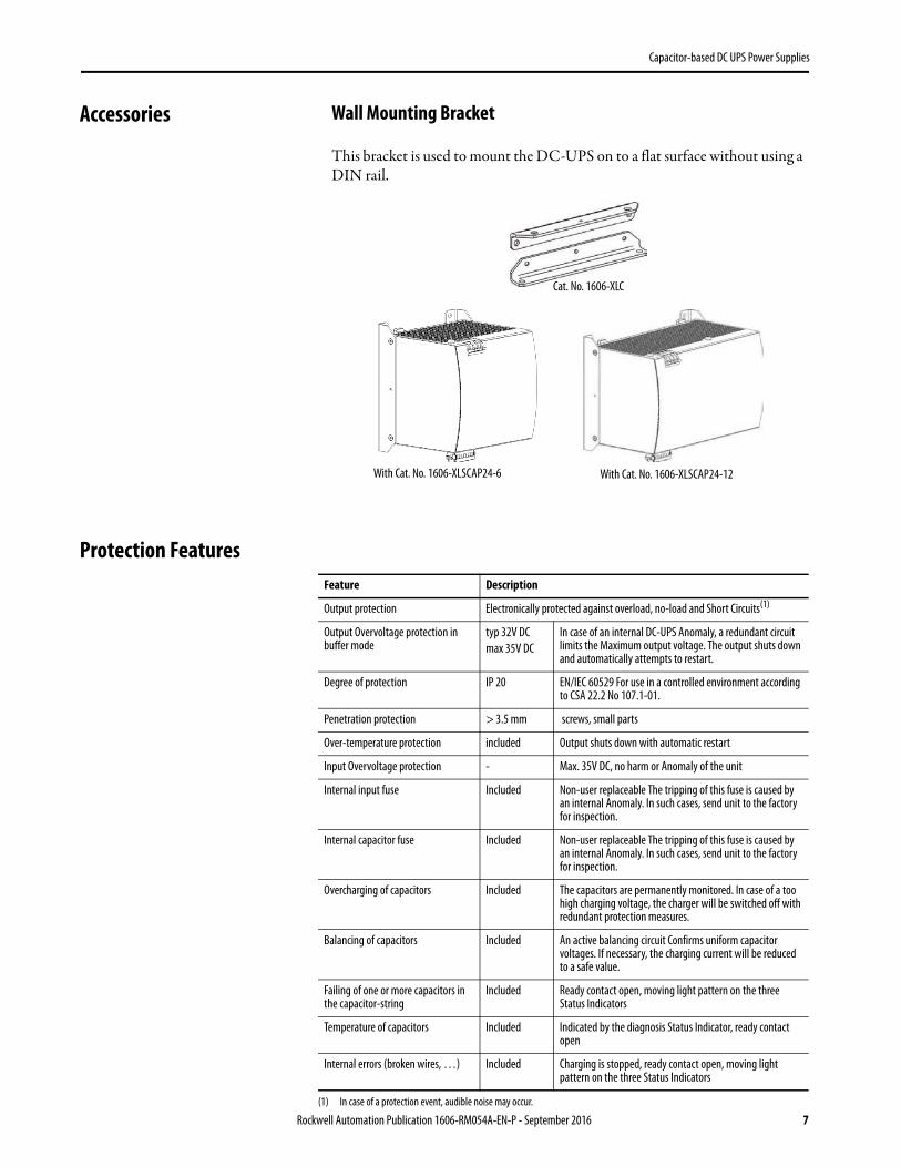
Accessories Wall Mounting Bracket
This bracket is used to mount the DC-UPS on to a flat surface without using a DIN rail.
Protection Features
With Cat. No. 1606-XLSCAP24-6 With Cat. No. 1606-XLSCAP24-12
Cat. No. 1606-XLC
Feature Description
Output protection Electronically protected against overload, no-load and Short Circuits(1)
Output Overvoltage protection in buffer mode
typ 32V DCmax 35V DC
In case of an internal DC-UPS Anomaly, a redundant circuit limits the Maximum output voltage. The output shuts down and automatically attempts to restart.
Degree of protection IP 20 EN/IEC 60529 For use in a controlled environment according to CSA 22.2 No 107.1-01.
Penetration protection > 3.5 mm screws, small parts
Over-temperature protection included Output shuts down with automatic restart
Input Overvoltage protection - Max. 35V DC, no harm or Anomaly of the unit
Internal input fuse Included Non-user replaceable The tripping of this fuse is caused by an internal Anomaly. In such cases, send unit to the factory for inspection.
Internal capacitor fuse Included Non-user replaceable The tripping of this fuse is caused by an internal Anomaly. In such cases, send unit to the factory for inspection.
Overcharging of capacitors Included The capacitors are permanently monitored. In case of a too high charging voltage, the charger will be switched off with redundant protection measures.
Balancing of capacitors Included An active balancing circuit Confirms uniform capacitor voltages. If necessary, the charging current will be reduced to a safe value.
Failing of one or more capacitors in the capacitor-string
Included Ready contact open, moving light pattern on the three Status Indicators
Temperature of capacitors Included Indicated by the diagnosis Status Indicator, ready contact open
Internal errors (broken wires, …) Included Charging is stopped, ready contact open, moving light pattern on the three Status Indicators
(1) In case of a protection event, audible noise may occur.

Capacitor-based DC UPS Power Supplies
Safety Features
Installation Notes • The DC-UPS can only be installed and put into operation by qualified personnel.
• The input must be powered from a Separated Extra-low Voltage (SELV) or Protected Extra-low Voltage (PELV) power source.
• The DC-UPS does not contain serviceable parts. The tripping of an internal fuse is caused by an internal anomaly. If damage or malfunction occurs during installation or operation, immediately turn power off and send unit to the factory for inspection.
• Mount the unit on a DIN rail so that the power terminals are on the top of the unit.
• The DC-UPS is designed for convection cooling and does not require an external fan. Do not obstruct airflow and do not cover ventilation grid (cable conduits) by more than 15%.
• Keep the following installation clearances: 40 mm (1.57 in.) on top, 20 mm (0.79 in.) on the bottom, 5 mm (0.20 in.) on the left and right sides are recommended when the DC-UPS is loaded permanently with more than 50% of the rated power. Increase this clearance to 15 mm (0.59 in.) in case the adjacent device is a heat source, such as a power supply.
Figure 5 - Typical Wiring Diagram
Attribute Value
Output voltage SELV IEC/EN 60950-1, The input must be powered from a SELV power source.
PELV IEC/EN 60204-1, EN 50178, IEC 62103, IEC 60364-4-41, The input must be powered from a PELV power source.
Class of protection III PE (Protective Earth) connection not required
Isolation resistance
> 5 MOhm> 800 kOhm> 5 MOhm
Power port to signal portPower port to housing Signal port to housing
Dielectric strength 500V AC500V AC
Power port to signal portPower port / signal port to housing
Touch current (leakage current)
The leakage current which is produced by the DC-UPS itself depends on the input voltage ripple and need to be investigated in the final application. For a smooth DC input voltage, the produced leakage current is less than 100 μA.
buffered branches
non-buffered branches
L N PE
+ + - -
PowerSupply
+ -24V Output
DC-UPS
IN+ -OUT
Read
yBu
ffer
ing
Inhi
bit
PC-M
ode
Input
+ -
8 Rockwell Automation Publication 1606-RM054A-EN-P - September 2016
Capacitor-based DC UPS Power Supplies
The EDLC (storage capacitors) contains Acetonitrile and Tetraethylammonium-tetrafluoroborate. These components are declared as non-dangerous goods regarding shipment.
Hazardous Location Information
The DC-UPS is suitable for use in Class I Division 2 Groups A, B, C, D locations and for use in Group II Category 3 (Zone 2) environments and are evaluated according to EN 60079-0 and EN 60079-15.
SHOCK HAZARD: Turn power off before working on the power supply. Avoid inadvertent repowering.• Make sure that the wiring is correct by following all local and
national codes.• Do not modify or repair the unit.• Do not open the unit as hazardous energy can be present inside. Info
for service personnel: Before opening the unit, wait at least 45 minutes after disconnecting the unit from input power so that the remaining capacitor charge has been fully discharged.
• Use caution so that foreign objects cannot enter the housing.• Do not use in wet locations or in areas where moisture or
condensation can be expected.
BURN HAZARD: Do not touch components during power-on, and immediately after power-off. Hot surfaces can cause burns.
WARNING: Explosion Hazard. Substitution of components can impair suitability for this environment. Do not disconnect the unit or change unit settings unless power has been switched off or the area is known to be non-hazardous. A suitable enclosure must be provided for the end product that has a minimum protection of IP54 and fulfills the requirements of the EN 60079-15.
Rockwell Automation Publication 1606-RM054A-EN-P - September 2016 9

Capacitor-based DC UPS Power Supplies
10 Rockwell Automation Publication 1606-RM054A-EN-P - September 2016
Terminals and Wiring The terminals are IP20 fingersafe constructed and suitable for field and factory wiring.
• Use appropriate copper cables that are designed for minimum operating temperatures of: – 60 °C (140 °F) for ambient temperatures up to 45 °C (113 °F)– 75 °C(167 °F) for ambient temperatures up to 60 °C (140 °F) – 90 °C (194 °F) for ambient temperatures up to 70 °C (158 °F)
• Follow national installation codes and installation regulations• Confirm that all strands of a stranded wire enter the terminal
connection• Unused terminal compartments should be securely tightened or closed• Ferrules are allowed
Figure 6 - Connecting a Wire
Attribute Input and Output Signals
Type Bi-stable quick-connect spring-clamp terminals Pluggable spring-clamp terminals
Solid wire, max 6 mm2 max1.5 mm2
Stranded wire, max 4 mm2 max1.5 mm2
American wire gauge AWG 20-10 AWG 24-14
Wire diameter, max 2.8mm (including ferrules) 1.5 mm (including ferrules)
Wire stripping length 10mm (0.4 in.) 8 mm (0.3 in.)
Screwdriver - 2.5 mm slotted
1. Insert the wire 2. Close the lever
To disconnect wire:reverse the procedure
Capacitor-based DC UPS Power Supplies
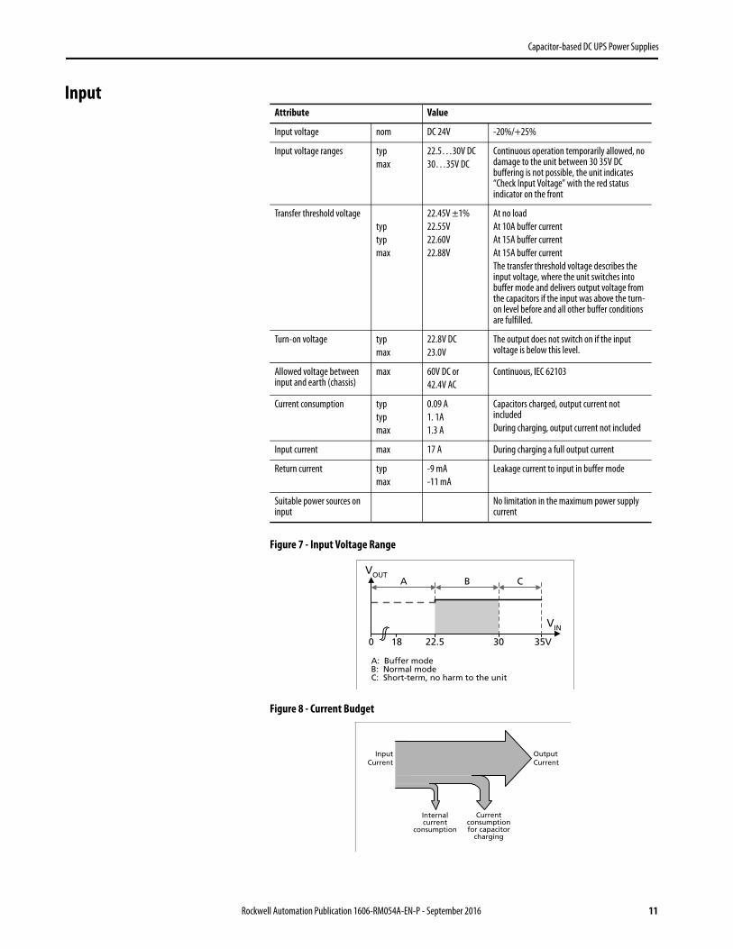
Input
Figure 7 - Input Voltage Range
Figure 8 - Current Budget
Attribute Value
Input voltage nom DC 24V -20%/+25%
Input voltage ranges typ max
22.5…30V DC 30…35V DC
Continuous operation temporarily allowed, no damage to the unit between 30 35V DC buffering is not possible, the unit indicates “Check Input Voltage” with the red status indicator on the front
Transfer threshold voltagetyp typ max
22.45V ±1% 22.55V 22.60V 22.88V
At no load At 10A buffer current At 15A buffer current At 15A buffer current The transfer threshold voltage describes the input voltage, where the unit switches into buffer mode and delivers output voltage from the capacitors if the input was above the turn-on level before and all other buffer conditions are fulfilled.
Turn-on voltage typ max
22.8V DC23.0V
The output does not switch on if the input voltage is below this level.
Allowed voltage between input and earth (chassis)
max 60V DC or42.4V AC
Continuous, IEC 62103
Current consumption typtypmax
0.09 A1. 1A 1.3 A
Capacitors charged, output current not includedDuring charging, output current not included
Input current max 17 A During charging a full output current
Return current typ max
-9 mA -11 mA
Leakage current to input in buffer mode
Suitable power sources on input
No limitation in the maximum power supply current
VOUT
A: Buffer modeB: Normal modeC: Short-term, no harm to the unit
VIN
18 30 35V22.50
A B C
Internalcurrent
consumption
Currentconsumptionfor capacitor
charging
OutputCurrent
InputCurrent
Rockwell Automation Publication 1606-RM054A-EN-P - September 2016 11

Capacitor-based DC UPS Power Supplies
Output The output section of the DC-UPS is fully controlled and is equipped with an electronic current limitation. A current overloading of the DC-UPS cannot happen, independent of which sizes of power supplies are used on the input of the DC-UPS. The current limitation works in a switching mode which reduces the power losses and heat generation to a minimum.
Output in normal mode:
In normal mode (and also in charging mode), the output voltage is slightly lower as the input voltage. The output voltage follows the input voltage reduced by the input to output voltage drop.
Output in buffer mode:
The output voltage is fully regulated in buffer mode. The unit switches into buffer mode, when the input voltage falls below the transfer threshold input voltage level. The buffer voltage is slightly lower than this threshold input voltage. The unit switches back to normal mode, as soon as the input voltage exceeds the transfer threshold voltage, which is specified in the input section.
Attribute Value
Input to output voltage drop max 0.3V 0.45V
At 10 A output currentAt 15 A output current
Ripple & noise voltage max 30 mVpp At 20 Hz to 20 MHz, 50 Ohm measurement. This figure indicates the ripple & noise voltage which is produced by the DC-UPS. It can be higher if the supplying source has a higher ripple and noise voltage
Output current nom 15 A Continuously allowed for the entire voltage range
Output power nom 360 W At 24V
Overload behavior Continuous current
See Figure 10 on page 13
Current limitation typmin
16 A 15 A
See Figure 10 on page 13
Short circuit current min 17.9 A Load impedance 100 m Ohm, See Figure 10 on page 13
max 21.0 A
Output capacitance typ 1 500 μF Included inside the DC-UPS
Capacitive and inductive loads No limitation
Attribute Value
Output voltage typ 22.45V ±1%
22.25V ±1%
22.12V ±1%
At no loadAt 10 A buffer currentAt 15 A buffer current
Ripple & noise voltage max 30 mVpp At 20 Hz to 20 MHz, 50 Ohm measurement
Output current nom 15 A Continuously allowed
Output power nom 360 W At 24V
Overload behavior Continuous current See Figure 10
Current limitation typ min
16 A 15 A
12 Rockwell Automation Publication 1606-RM054A-EN-P - September 2016

Capacitor-based DC UPS Power Supplies
Short circuit current min 17.9 A Load impedance 70m Ohm, See Figure 10
max 21.0 A Load impedance 50m Ohm, See Figure 10
Capacitive and inductive loads No limitation
Attribute Value
Figure 9 - Input to Output Voltage Drop in Normal Mode, typ Figure 11 - Output Characteristics and Overload Behavior in Normal and Buffer Modes, typ
Figure 10 - Transition from Normal to Buffer Mode and Vice Versa, Definitions
Figure 12 - Input to Output Voltage Drop in Normal Mode
00 2 10
100mV
16A
400mv
Output Current
4 6 8 12 14
200mv
300mv
Voltage drop
Output Voltage
00 5 10 15 20
4
8
12
28V
16
20
24
25 A
Output Current
Buffer
Outputvoltage
24V
mode
Inputvoltage
t
t
Transfer threshold
24VNormal
modeNormal
mode
500ms/DIV
0 V
Output Voltage
Input Voltage
2 4 V
22.25V at 10A
2 4 V
Rockwell Automation Publication 1606-RM054A-EN-P - September 2016 13

Capacitor-based DC UPS Power Supplies
Charging During charging, the DC-UPS consumes additional current from the input. Refer to Input on page 11.
When charging is completed, the Ready status indicator stops updating and is on solid and the Ready relay contact closes.
Buffer Time The following times are typical values for a new product and the aging effect during operation is not included. More information about the reduction of the buffer time over the life of the product can be found in “Lifetime Expectancy and MTBF”
Attribute 1606-XLSCAP24-6 1606-XLSCAP24-12 Notes
Charging time— initial charging(1)
(1) Initial charging means that no input voltage was applied for several hours or longer and the capacitor is fully discharged by the internal electronics.
typ 16 minutes 32 minutes When capacitor is fully discharged.
Charging time —recharging
(2)
(2) Recharging means that the electronics inside the DC-UPS has not fully discharged the capacitor. The values in the table apply when the input voltage is applied immediately after buffering has stopped.
typ 1 minute 50s 1 minute 50s After discharging with 10 A for 10s
typ 3 minutes 50s 7 minutes 40s After discharging with 10 A until buffering stops
typ 4 minutes 40s 9 minutes 40s After discharging with 5 A until buffering stops
typ 5 minutes 40s 11 minutes 15s After discharging with 1 A until buffering stops
Allowed number of charging/ discharging cycles No limitation No limitation
IMPORTANT At the end of the charging process the active balancing circuit reduces the charging current periodically, which can be seen as current oscillations on the input current.
Buffer Current [A] Buffer Time [s]
1606-XLSCAP24-6 1606-XLSCAP24-12
0 typ 1650 3300
0.5 340 680
1 200 400
3 68 136
5 39 78
7 26 53
10 16.5 33
15 9 18
14 Rockwell Automation Publication 1606-RM054A-EN-P - September 2016

Capacitor-based DC UPS Power Supplies
Figure 13 - Buffer Times vs. Buffer Current
Ready and Buffer Relay Contact
The DC-UPSs are equipped with two independent relay contacts for remote monitoring and controlling of the unit.
Relay Contact
Contact is closed when capacitor is fully charged, input voltage is sufficient and inhibit signal is not active.
Buffering Contact
Contact is closed when unit is buffering.
Buffer Current
0 20 200s40 60 80 100 120 140 160 180Buffer Times
a b
0
6A
4A
16A
8A
2A
10A
12A
14A1606-XLSCAP24-61606-XLSCAP24-12
a
b
Attribute Value
Contact ratings max
60V DC – 0.3A30V DC – 1A30V AC – 0.5A
Resistive load
min 1 mA at 5V DC Minimum permissible load
Isolation voltage 500V AC, signal port to power port
Attribute Value
Contact ratings max
60V DC, 0.3 A30V DC , 1 A30V AC , 0.5 A
Resistive load
min 1 mA at 5V DC Minimum permissible load
Isolation voltage 500V AC, signal port to power port
Rockwell Automation Publication 1606-RM054A-EN-P - September 2016 15

Capacitor-based DC UPS Power Supplies
Inhibit Input The inhibit input disables buffering. In normal mode, a static signal is required. In buffer mode, a pulse with a minimum length of 250 ms is required to stop buffering. The inhibit is stored and can be reset by cycling the input voltage.
Figure 14 - Inhibit Input
PC-mode The PC-mode turns the output off for at least 5 seconds after a buffer event lasting longer than 1 second, independent of whether the 24V input power has recovered during this time. This function verifies that the personal computer receives a restart signal. To enable a proper shutdown of the system, the forced turn off of the output is delayed with a constant time of 70 seconds.
To activate the PC-mode, connect the two pins marked with “PC-mode” together on the signal connector together. If the personal computer, not the DC-UPS, controls the reset, a wiring option called 'external controlled delayed shutdown' is available.
Attribute Value
Signal voltage max 35V DC
Signal current max 6 mA, current limited
Inhibit threshold minmax
6V DC, buffering is disabled above this threshold level10V DC
Isolation voltage 500V AC, signal port to power port
7 +
5.1V
3mA
Inhibit
8 -
Figure 15 - PC-mode, Buffer Event Ends Before Buffer Capacitors are Discharged and Buffer Event is Shorter than 70 seconds
Figure 16 - PC-mode, Buffer event discharges the buffer capacitors before the input recovers.
Example A: The buffer event is longer than 1s and ends before the buffer capacitors are fully discharged. After 70 seconds of the beginning of the buffer event, the output of the DC-UPS will be switched off for 5 seconds
Example B: The buffer event lasts longer than the buffer capacitors can supply the output. The buffer capacitors are fully discharged before the input voltage recovers. The DC-UPS output will turn on at the earliest 5 seconds after the power supply output voltage has recovered.
>1s
Power Supply Output
DC-UPS Output
full
emptyCapacitor
ReadyContact
closed
open
BufferingContact
closed
open
5s70s
Power Supply Output
DC-UPS Output
full
emptyCapacitor
ReadyContact
closed
open
BufferingContact
closed
open
5s
16 Rockwell Automation Publication 1606-RM054A-EN-P - September 2016

Capacitor-based DC UPS Power Supplies
Efficiency and Power Loss
Lifetime Expectancy and Mean Time Between Failure
The lifetime expectancy of the DC-UPS is predominantly affected by the storage capacitors. The biggest influence in lifetime is a combination of operating voltage and operating temperature of these capacitors. To gain longest lifetimes, Rockwell Automation does not use the full allowed working voltage for these capacitors and therefore accepts a slightly shorter buffer time.
The EDLC’s do not experience a true End of Life, rather the capacitance continually degrades over the life of the DC-UPS. The typical degradation behavior resembles that of a exponential decay in the first couple of 1000 hours followed by a linear degradation. The majority of the capacitance reduction occurs during the initial use of the DC-UPS and this change in performance then levels off over time. When working with the specified lifetime numbers, the remaining capacity must always be taken into account. The buffer time correlates linearly to the capacity.
The ultracapacitors have an almost unlimited shelf life (unlike batteries) when stored uncharged at 25 °C (44 °F).
Attribute Value
Efficiency typ 97.8% Normal mode, 10 A output current, capacitor fully charged.
typ 97.8% Normal mode, 15 A output current, capacitor fully charged.
Power losses typ 2.9 W Normal mode, 0 A output current, capacitor fully charged.
typ 4.6 W Normal mode, 10 A output current, capacitor fully charged.
typ 7.7 W Normal mode, 15 A output current, capacitor fully charged.
typ 5.0 W During charging, 0 A output current
Figure 17 - Efficiency vs. Output Current Figure 18 - Power Losses vs. Output Current
Efficiency vs. outputcurrent in normal mode
94.53 9
95.596.0
97.0
15A
95.0
96.5
97.598%
O u t p u t C u r r e n t
5 7 11 13
Power losses versus outputcurrent in normal mode
00 7 . 5
2
5
15A
34
78W
O u t p u t C u r r e n t
2.5 5 10 12.5
1
6
Rockwell Automation Publication 1606-RM054A-EN-P - September 2016 17
Capacitor-based DC UPS Power Supplies
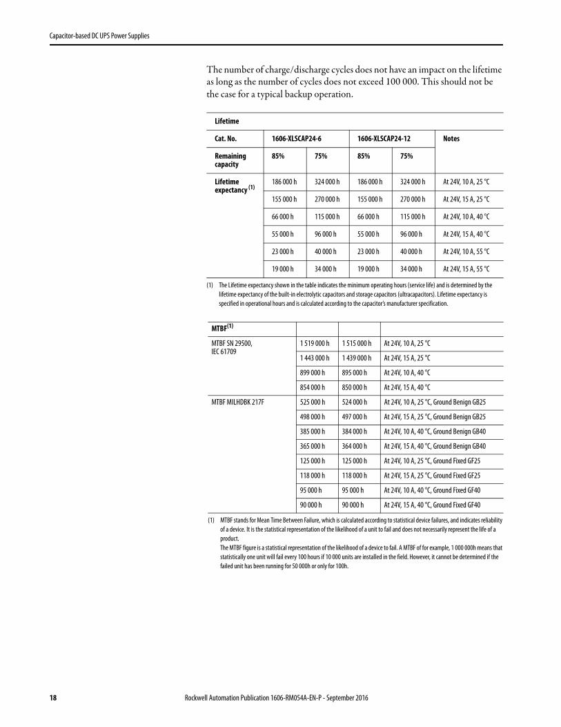
The number of charge/discharge cycles does not have an impact on the lifetime as long as the number of cycles does not exceed 100 000. This should not be the case for a typical backup operation.
Lifetime
Cat. No. 1606-XLSCAP24-6 1606-XLSCAP24-12 Notes
Remaining capacity
85% 75% 85% 75%
Lifetime expectancy (1)
(1) The Lifetime expectancy shown in the table indicates the minimum operating hours (service life) and is determined by the lifetime expectancy of the built-in electrolytic capacitors and storage capacitors (ultracapacitors). Lifetime expectancy is specified in operational hours and is calculated according to the capacitor’s manufacturer specification.
186 000 h 324 000 h 186 000 h 324 000 h At 24V, 10 A, 25 °C
155 000 h 270 000 h 155 000 h 270 000 h At 24V, 15 A, 25 °C
66 000 h 115 000 h 66 000 h 115 000 h At 24V, 10 A, 40 °C
55 000 h 96 000 h 55 000 h 96 000 h At 24V, 15 A, 40 °C
23 000 h 40 000 h 23 000 h 40 000 h At 24V, 10 A, 55 °C
19 000 h 34 000 h 19 000 h 34 000 h At 24V, 15 A, 55 °C
MTBF(1)
(1) MTBF stands for Mean Time Between Failure, which is calculated according to statistical device failures, and indicates reliability of a device. It is the statistical representation of the likelihood of a unit to fail and does not necessarily represent the life of a product.The MTBF figure is a statistical representation of the likelihood of a device to fail. A MTBF of for example, 1 000 000h means that statistically one unit will fail every 100 hours if 10 000 units are installed in the field. However, it cannot be determined if the failed unit has been running for 50 000h or only for 100h.
MTBF SN 29500, IEC 61709
1 519 000 h 1 515 000 h At 24V, 10 A, 25 °C
1 443 000 h 1 439 000 h At 24V, 15 A, 25 °C
899 000 h 895 000 h At 24V, 10 A, 40 °C
854 000 h 850 000 h At 24V, 15 A, 40 °C
MTBF MILHDBK 217F 525 000 h 524 000 h At 24V, 10 A, 25 °C, Ground Benign GB25
498 000 h 497 000 h At 24V, 15 A, 25 °C, Ground Benign GB25
385 000 h 384 000 h At 24V, 10 A, 40 °C, Ground Benign GB40
365 000 h 364 000 h At 24V, 15 A, 40 °C, Ground Benign GB40
125 000 h 125 000 h At 24V, 10 A, 25 °C, Ground Fixed GF25
118 000 h 118 000 h At 24V, 15 A, 25 °C, Ground Fixed GF25
95 000 h 95 000 h At 24V, 10 A, 40 °C, Ground Fixed GF40
90 000 h 90 000 h At 24V, 15 A, 40 °C, Ground Fixed GF40
18 Rockwell Automation Publication 1606-RM054A-EN-P - September 2016

Capacitor-based DC UPS Power Supplies
Figure 19 - Lifetime Expectancy vs. Ambient Temperature at 10 A Output Current
Figure 20 - Lifetime Expectancy vs. Ambient Temperature at 15 A Output Current
Functional Diagram
Lifetime hours
0 35 40 45 55°C
20 000 2.3
Ambient Temperature
40 000
60 000
80 000
100 000
120 000Lifetime years
4.6
6.9
9.2
11.6
13.9
50
A
Remaining capacity:A: 85%B: 75%B
10A Output Current
Lifetime hours
0 35 40 45 55°C
20 000 2.3
Ambient Temperature
40 000
60 000
80 000
100 000
120 000Lifetime years
4.6
6.9
9.2
11.6
13.9
50
A
Remaining capacity:A: 85%B: 75%B
15A Output Current
-
+
24VPowerSupply
BoostConverter(Step-up
Converter)Charger
Balancing&
SafetyCircuits
Input
ElectronicCurrentLimiter
+
-
BufferedLoad
Output
Diagnosis LED (yellow)
Status LED (green)
+
Controller
Warning (red)
BufferingContact
Ready Contact
(5)-(6)
(1)(2)
(3)(4)
StorageCapacitors
Input Fuse,Reverse Polarity Protection,Return Current Protection
Temp
InputVoltageMonitor
Inhibit
(7)(8)
PC-Mode
ChassisGround
Rockwell Automation Publication 1606-RM054A-EN-P - September 2016 19

Capacitor-based DC UPS Power Supplies
EMC The DC-UPS is suitable for applications in industrial environment as well as in residential, commercial and light industry environment without any restrictions.
EMC Immunity - According to generic standards: EN 61000-6-1 and EN 61000-6-2
Electrostatic discharge (1)
(1) Chassis ground connection earthed (grounded)
EN 61000-4-2 Contact dischargeAir discharge
8 kV 15 kV
Criterion A(3)
(3) Criterion A: DC-UPS shows normal operation behavior within the defined limits.
Electromagnetic RF field
EN 61000-4-3 80 MHz…2.7 GHz 10 V/m
Fast transients (Burst) EN 61000-4-4 Input lines output lines signals(2)
(2) Tested with coupling clamp
2 kV 2 kV 2 kV
Surge voltage on input EN 61000-4-5 + -+/ -chassis ground
500V 1kV
Surge voltage on output
EN 61000-4-5 + -+/ -chassis ground
500V 1 kV
Surge voltage on inhibit input, ready- and buffering contacts and PC-mode selector
EN 61000-4-5 Signals chassis ground 1 kV
Conducted disturbance EN 61000-4-6 0.15…80 MHz 10V
EMC Emission
Conducted emission
IEC/CISPR 16-1-2, IEC/CISPR 16-2-1 Input lines Limits for DC power ports acc. EN 61000-6-3 fulfilled
IEC/CISPR 16-1-2, IEC/CISPR 16-2-1 Output lines
Radiated emission EN 55011, EN 55022 Class B
This device complies with FCC Part 15 rules. Operation is subjected to following two conditions: (1) this device may not cause harmful interference, and (2) this device must accept any interference received, including interference that may cause undesired operation.
Switching Frequencies The unit has two converters with two different switching frequencies and one switch-mode current limiter included.
100 kHz Boost Converter (active only in buffer mode) Switching frequency 1
78 kHz Electronic output current limitation Switching frequency 2
19.5 kHz Charger Switching frequency 3
20 Rockwell Automation Publication 1606-RM054A-EN-P - September 2016

Capacitor-based DC UPS Power Supplies
Application Notes External Input Protection
The DC-UPS is tested and approved for branch circuits up to 50A. An external protection is only required, if the supplying branch has an ampacity greater than this. If an external fuse is necessary or uses, minimum requirements need to be considered to avoid nuisance tripping of the circuit breaker. A minimum value of 20A B- or C-Characteristic breaker should be used.
Check also local codes and local requirements. In some countries local regulations might apply.
Output Circuit Breakers
The output of the DC-UPS is equipped with an electronic current limitation. An overload or Short Circuit on the output is electronically protected and cannot cause any harms, independent of which sizes of power supplies are used on the input of the DC-UPS.
However, some applications require branch circuit or branch circuit conductor protection. Therefore standard miniature circuit breakers (MCBs) or UL 1077 circuit breaker) are commonly used on 24V branches.
MCBs are designed to protect wires and circuits. If the ampere value and the characteristics of the MCB are adapted to the wire size that is used, the wiring is considered as thermally safe regardless of whether the MCB opens or not.
To avoid voltage dips and undervoltage situations in adjacent 24V branches which are supplied by the same source, a fast (magnetic) tripping of the MCB is desired. A quick shutdown within 10ms is necessary corresponding roughly to the ride-through time of PLCs. This requires high peak currents to open the circuit breaker in the required time. Furthermore, the impedance of the faulty branch must be sufficiently small in order for the current to actually flow. The following table has typical test results showing which C-Characteristic MCBs magnetically trip depending on the wire cross section and wire length.
Figure 21 - Test Circuit
Test circuit Maximal wire length *) for a fast (magnetic) tripping: 0.75mm2 1.0mm2 1.5mm2 2.5mm2 C-2A 20m 25m 39m 58m C-3A 12m 14m 24m 39m C-4A 3m 3m 4m 4m
MCB
DC-UPSOutput
+
-
Load
+
-
Wire length
S1... Fault simulation switch
S1
*) Important: You must consider twice the distance to the load (or cable length) when calculating the total wire length (+ and - wire).
Rockwell Automation Publication 1606-RM054A-EN-P - September 2016 21
Capacitor-based DC UPS Power Supplies
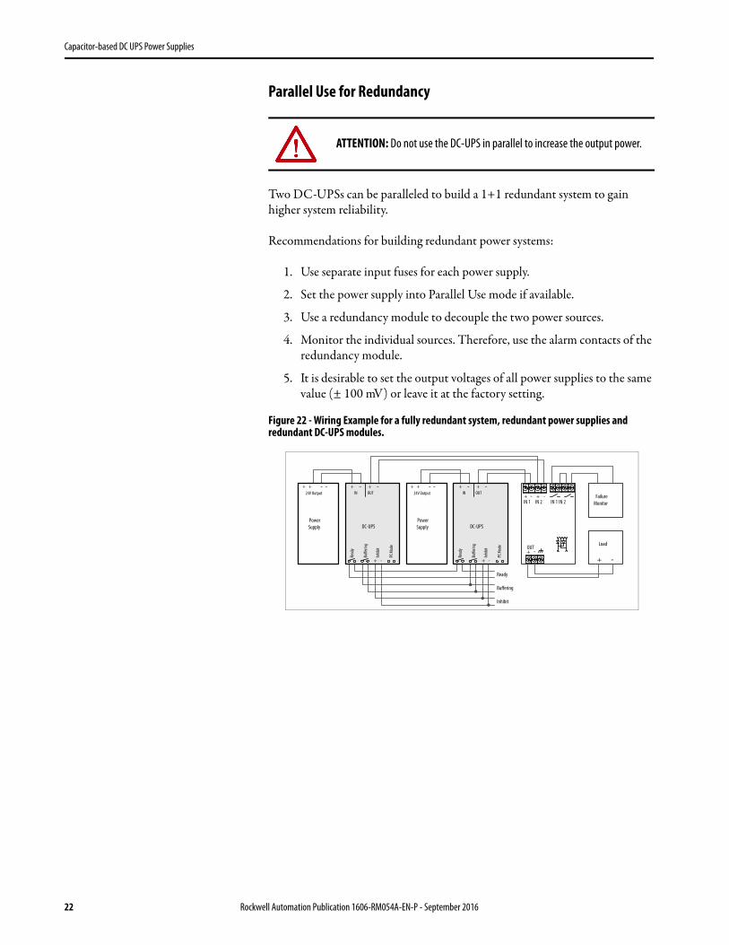
Parallel Use for Redundancy
Two DC-UPSs can be paralleled to build a 1+1 redundant system to gain higher system reliability.
Recommendations for building redundant power systems:
1. Use separate input fuses for each power supply.
2. Set the power supply into Parallel Use mode if available.
3. Use a redundancy module to decouple the two power sources.
4. Monitor the individual sources. Therefore, use the alarm contacts of the redundancy module.
5. It is desirable to set the output voltages of all power supplies to the same value (± 100 mV) or leave it at the factory setting.
Figure 22 - Wiring Example for a fully redundant system, redundant power supplies and redundant DC-UPS modules.
ATTENTION: Do not use the DC-UPS in parallel to increase the output power.
+ + - -
PowerSupply
24V Output+ + - -
PowerSupply
24V Output
Load
+ -
FailureMonitor
+ -OUT
+ -IN 1
+ -IN 2 IN 1 IN 2
Ready
Buffering
Inhibit
DC-UPS
IN OUT+ + --
Inhib
it
+ -
Read
y
Buffe
ring
PC M
ode
DC-UPS
IN OUT+ + --
Inhib
it
+ -
Read
y
Buffe
ring
PC M
ode
22 Rockwell Automation Publication 1606-RM054A-EN-P - September 2016

Capacitor-based DC UPS Power Supplies
Parallel User for Longer Buffer Times
DC-UPSs can be paralleled to extend the buffer time.
Figure 23 - Wiring Example for Parallel Use for Longer Buffer Times.
Series Use for 48V ApplicationsA series connection for 48V applications is allowed when using two individual power supplies and two DC-UPSs.
Figure 24 - Wiring Example for 48V Serial Use
Using the Inhibit-InputThe inhibit-input disables buffering. In normal mode, a static signal is required. In buffer mode, a pulse with a minimum length of 250 ms is required to stop buffering. The inhibit signal is stored and can be reset by cycling the input voltage.
For service purposes, the inhibit input can also be used to connect a service switch. Therefore, the inhibit signal can be supplied from the output of the DC-UPS.
Figure 25 - Wiring Example for Inhibit Input
+ + - -
Power
24V Output
Supply
Load
+ -
Ready
Buffering
Inhibit
DC-UPS
IN OUT+ + --
DC-UPS
IN OUT+ + --
DC-UPS
IN OUT+ + --
Inh
ibit
+ -
Rea
dy
Bu
ffer
ing
Inh
ibit
+ -
Rea
dy
Bu
ffer
ing
Inh
ibit
+ -
Rea
dy
Bu
ffer
ing
PC M
od
e
PC M
od
e
PC M
od
e
+ + - -
PowerSupply
24V Output+ + - -
PowerSupply
24V Output
DC-UPS
IN OUT+ + --
DC-UPS
IN OUT+ + --
Inh
ibit
+ -
Rea
dy
Bu
ffer
ing
PC M
od
e
Inh
ibit
+ -
Rea
dy
Bu
ffer
ing
PC M
od
e
48VLoad
+ -
24VPowerSupply
+ -
BufferedLoad
+ -
DC-UPS
OUTIN
+ - + -
ServiceSwitch
Inh ib
i t
+ -
R e a d y
B u f fe r in
g
P C Mo d e
Rockwell Automation Publication 1606-RM054A-EN-P - September 2016 23
Capacitor-based DC UPS Power Supplies
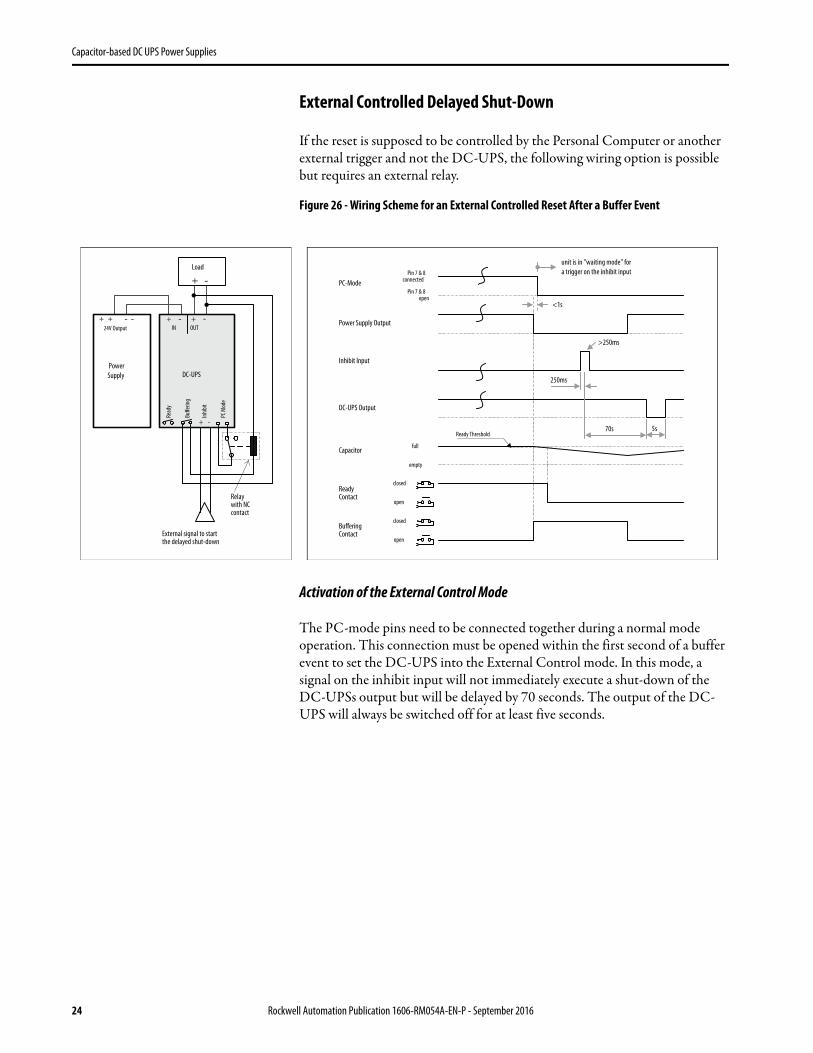
External Controlled Delayed Shut-Down
If the reset is supposed to be controlled by the Personal Computer or another external trigger and not the DC-UPS, the following wiring option is possible but requires an external relay.
Figure 26 - Wiring Scheme for an External Controlled Reset After a Buffer Event
Activation of the External Control Mode
The PC-mode pins need to be connected together during a normal mode operation. This connection must be opened within the first second of a buffer event to set the DC-UPS into the External Control mode. In this mode, a signal on the inhibit input will not immediately execute a shut-down of the DC-UPSs output but will be delayed by 70 seconds. The output of the DC-UPS will always be switched off for at least five seconds.
+ + - -
PowerSupply
24V Output
DC-UPS
IN OUT+ + --
Inhib
it
+ -
Read
y
Buffe
ring
PC M
ode
Relaywith NCcontact
Power Supply Output
DC-UPS Output
5s70s
PC-ModePin 7 & 8
connected
unit is in "waiting mode" fora trigger on the inhibit input
Inhibit Input
>250ms
ReadyContact
closed
External signal to startthe delayed shut-down
Load
+ -
open
closedBufferingContact
open
<1s
full
empty
Capacitor
Pin 7 & 8open
Ready Threshold
250ms
24 Rockwell Automation Publication 1606-RM054A-EN-P - September 2016

Capacitor-based DC UPS Power Supplies
KJ and KWS Explanation
The units kJ (kilo Joule) or kWs (kilo Watt seconds) is used for specifying the installed storage capacitor size.
1 kJ = 1 kWs = 1000Ws
The stored energy of a capacitor can be calculated with the following formula:
For example: A 350F (Farad) capacitor which is charged to 2.5V has the following energy
During discharging of the capacitor, the voltage decreases with the amount of discharge. A boost converter is needed to generate a stable output voltage. The boost converter needs a minimum input voltage (cutoff voltage), which reduces the amount of energy. The cutoff voltage usually depends on the load current, the lower the load current, the lower the cutoff voltage. Considering this voltage range, the energy can be calculated with the following formula (full charge voltage= U1= 2.5V, cutoff voltage= U2= 1V):
The energy which can be used for the 24V loads is further reduced by the efficiency of the boost converter.
Catalog number 1606-XLSCAP24-6 has a rated capacitor size of 6 kWs and the catalog number 1606-XLSCAP24-12, 12 kWs. This is the energy which can be used for 24V load at low load currents.
Calculation of the Needed Energy
EXAMPLE 45W of power is needed for two minutes: Always check with the buffer time curve See Figure 11 on page 13, if the load can be powered for the required period of time 26/27
Energy(Ws) = C *U 2
2
*2.5E = 350F V
2
2=1093Ws =1.09kWs
E =C *(U12 −U22)
=350*(2.52 −12)
= 919Ws = 0.92kWs 2 2
Rockwell Automation Publication 1606-RM054A-EN-P - September 2016 25
Capacitor-based DC UPS Power Supplies
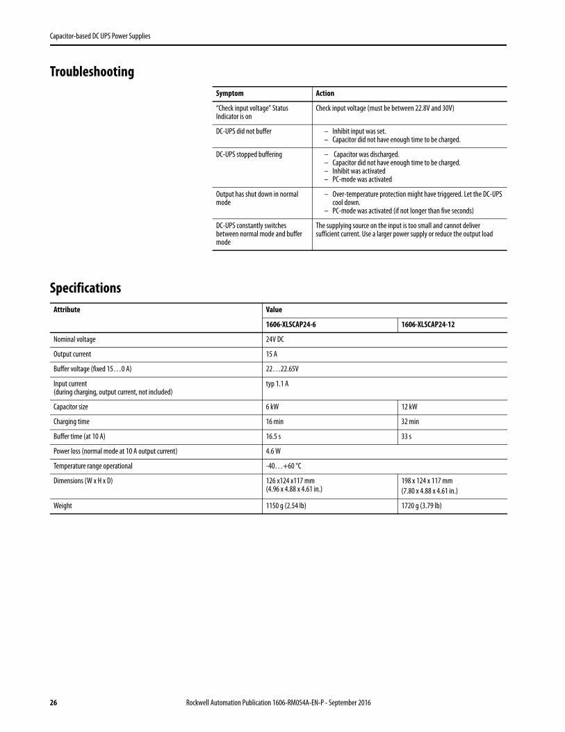
Troubleshooting
Specifications
Symptom Action
“Check input voltage” Status Indicator is on
Check input voltage (must be between 22.8V and 30V)
DC-UPS did not buffer – Inhibit input was set.– Capacitor did not have enough time to be charged.
DC-UPS stopped buffering – Capacitor was discharged. – Capacitor did not have enough time to be charged. – Inhibit was activated– PC-mode was activated
Output has shut down in normal mode
– Over-temperature protection might have triggered. Let the DC-UPS cool down.
– PC-mode was activated (if not longer than five seconds)
DC-UPS constantly switches between normal mode and buffer mode
The supplying source on the input is too small and cannot deliver sufficient current. Use a larger power supply or reduce the output load
Attribute Value
1606-XLSCAP24-6 1606-XLSCAP24-12
Nominal voltage 24V DC
Output current 15 A
Buffer voltage (fixed 15…0 A) 22…22.65V
Input current (during charging, output current, not included)
typ 1.1 A
Capacitor size 6 kW 12 kW
Charging time 16 min 32 min
Buffer time (at 10 A) 16.5 s 33 s
Power loss (normal mode at 10 A output current) 4.6 W
Temperature range operational -40…+60 °C
Dimensions (W x H x D) 126 x124 x117 mm (4.96 x 4.88 x 4.61 in.)
198 x 124 x 117 mm(7.80 x 4.88 x 4.61 in.)
Weight 1150 g (2.54 lb) 1720 g (3.79 lb)
26 Rockwell Automation Publication 1606-RM054A-EN-P - September 2016

Capacitor-based DC UPS Power Supplies
Environment Figure 27 - Output Current vs. Ambient Temperature
0-40 0 +40 +60°C
2.5
5.0
7.5
10.0
12.5
15A
Ambient Temperature
Allowable Output Current
Attribute Value
Operational temperature (1) -40 …+60 °C (-40 …+140 °F)
Storage temperature -40 …+70 °C (-40…+58 °F) For storage and transportation
Humidity(2) 5 …95% r.H. IEC 60068-2-30
Vibration sinusoidal(3) 2…7.8 Hz: ±1.6 mm; 17.8…500 Hz: 2 g2 hours / axis
IEC 60068-2-6
Shock(4) 30 g 6 ms, 20 g 11 ms) 3 bumps / direction, 18 bumps in total
IEC 60068-2-27
Altitude 0…6000m (0…20 000ft) Approvals apply only up to 2000 m
Overvoltage category II IEC 62103, EN 50178, EN 60950, UL 840
Degree of pollution 2 IEC 62103, EN 50178, not conductive
LABS compatibility The unit does not release any silicone or other LABS-critical substances and is suitable for use in paint shops.
(1) Operational temperature is the same as the ambient or surrounding temperature and is defined as the air temperature 2cm below the unit.
(2) Do not energize while condensation is present
(3) Higher levels allowed when using wall mounting bracket
(4) Higher levels allowed when using wall mounting bracket
Rockwell Automation Publication 1606-RM054A-EN-P - September 2016 27

Capacitor-based DC UPS Power Supplies
Standards Compliance and Certifications
EC Declaration of Conformity The CE Marking indicates conformance with the EMC directive and the RoHS directive.
UL 508 Listed for use as Industrial Control Equipment;U.S.A. (UL 508) and Canada (C22.2 No. 107-1-01); E-File: E198865
UL 60950-12nd Edition
Recognized for use as Information Technology Equipment,Level 5; U.S.A. (UL 60950-1) and Canada (C22.2 No. 60950-1);E-File: E137006. Applicable for altitudes up to 2000m.
RoHS Directive Directive 2011/65/EU of the European Parliament and the Council of June 8th, 2011 on the restriction of the use of certain hazardous substances in electrical and electronic equipment.
REACH Directive Directive 1907/2006/EU of the European Parliament and the Council of June 1st, 2007 regarding the Registration, Evaluation, Authorization and Restriction of Chemicals (REACH)
RCM Declaration of Conformity
IND. CONT. EQ.
28 Rockwell Automation Publication 1606-RM054A-EN-P - September 2016

Capacitor-based DC UPS Power Supplies
Approximate Dimensions and Weight
Attribute 1606-XLSCAP24-6 1606-XLSCAP24-12
Weight 1150 g (2.54 lb) 1720 g (3.79 lb)
DIN rail Use 35 mm DIN Rails according to EN 60715 or EN 50022 with a height of 7.5 or 15mm. The DIN rail height must be added to the unit depth (127 mm) to calculate the total required installation depth.
Installation clearances Refer to Protection Features on page 7
StatusDiagnosis
Warning
+ - + -IN OUT
+ -
ReadyBufferingInhibitPC-mode
198 mm (7.8 in.)
StatusDiagnosis
Warning
+ - + -IN OUT
+ -
ReadyBufferingInhibitPC-mode
126 mm (4.96 in.)
1606-XLSCAP24-6 1606-XLSCAP24-12
124
mm
(4.8
8 in
.)117 mm (4.61 in.)
DIN rail depth
Plug connectorfor signals
Rockwell Automation Publication 1606-RM054A-EN-P - September 2016 29

Capacitor-based DC UPS Power Supplies
Notes:
30 Rockwell Automation Publication 1606-RM054A-EN-P - September 2016

Publication 1606-RM054A-EN-P - September 2016Copyright © 2016 Rockwell Automation, Inc. All rights reserved. Printed in the U.S.A.
Rockwell Automation SupportUse the following resources to access support information.
Documentation FeedbackYour comments will help us serve your documentation needs better. If you have any suggestions on how to improve this document, complete the How Are We Doing? form at http://literature.rockwellautomation.com/idc/groups/literature/documents/du/ra-du002_-en-e.pdf.
Technical Support Center Knowledgebase Articles, How-to Videos, FAQs, Chat, User Forums, and Product Notification Updates. https://rockwellautomation.custhelp.com/
Local Technical Support Phone Numbers Locate the phone number for your country. http://www.rockwellautomation.com/global/support/get-support-now.page
Direct Dial Codes Find the Direct Dial Code for your product. Use the code to route your call directly to a technical support engineer. http://www.rockwellautomation.com/global/support/direct-dial.page
Literature Library Installation Instructions, Manuals, Brochures, and Technical Data. http://www.rockwellautomation.com/global/literature-library/overview.page
Product Compatibility and Download Center (PCDC)
Get help determining how products interact, check features and capabilities, and find associated firmware. http://www.rockwellautomation.com/global/support/pcdc.page
.
Rockwell Otomasyon Ticaret A.Ş., Kar Plaza İş Merkezi E Blok Kat:6 34752 İçerenköy, İstanbul, Tel: +90 (216) 5698400
Rockwell Automation maintains current product environmental information on its website at http://www.rockwellautomation.com/rockwellautomation/about-us/sustainability-ethics/product-environmental-compliance.page.
Allen-Bradley, Rockwell Automation, and Rockwell Software are trademarks of Rockwell Automation, Inc.
Trademarks not belonging to Rockwell Automation are property of their respective companies.


