Capillary-Driven Flow in Supported Capillary Pipes David B. Thiessen, Jorge Bernate, and Philip L. Marston Washington State University, Department of Physics and Astronomy Introduction Open-channel capillary flows where the free surface is supported by solid structures such as helices or regular polygonal arrays of parallel wires are possible at low Bond number [1]. The term “supported capillary pipe” will sometimes be used to refer to these open fluid channels. A photograph of a static helical supported capillary pipe is seen in Fig. 4(a). Low Bond number (Bo=gD 2 Δρ/σ) can be achieved in microgravity (g~0), at small scale in microfluidic applications (D~0), and in Plateau tank experiments (Δρ∼0). Supported capillary pipes may have applications to liquid-gas contacting in situations for which gravity is ineffective at creating the differential flow between a liquid and gas which is necessary to enhance transport rates. Applications in microgravity or at microscale can be imagined for chemical or biochemical processing and for heat transfer with phase change. Scaled down liquid-gas contactors may be useful for intensified processes such as lab-on-a- chip, high heat flux cooling of computer chips and for compact fuel reforming units to be used in fuel cell powered vehicles. To intensify heat or mass transfer operations in two phase systems one wishes to increase the interfacial area and provide good mixing near the free surface. The capillary structures discussed here would allow for improved surface area per volume compared to conventional processing equipment such as packed beds or structured packings. An advantage of the types of flow channels considered in this research is that they can be arranged in a close packed array to fill a three dimensional space. Scaling arguments suggest that velocity gradients near the free surface will be enhanced when the capillary flow channels are scaled down thus improving mass transfer rates. The static stability of liquid ridges in zero gravity in which the free surface is a section of a cylinder have been studied for the case of pinned and free contact lines [2-4]. Langbein [3] studied the case for which the liquid occupied an interior or exterior corner, Roy and Schwartz [4] considered the case of a solid cylindrical substrate, and Brown and Scriven [2] looked at liquid in a slot where the contact line is pinned at the exterior slot corners. The case of liquid in a slot with pinned contact lines is closely related to the stability of supported capillary pipes in polygonal wire arrays. The kinetics of initial meniscus penetration into an open channel has been shown to follow the classical Washburn [5] kinetics. This includes flow into a v-shaped groove [6-8], capillary flow in fiber matrices [9] and yarns [10], and flow along the corners of a
Transcript
Capillary-Driven Flow in Supported Capillary Pipes David B. Thiessen, Jorge Bernate, and Philip L. Marston Washington State University, Department of Physics and Astronomy Introduction
Open-channel capillary flows where the free surface is supported by solid structures such as helices or regular polygonal arrays of parallel wires are possible at low Bond number [1]. The term “supported capillary pipe” will sometimes be used to refer to these open fluid channels. A photograph of a static helical supported capillary pipe is seen in Fig. 4(a). Low Bond number (Bo=gD2Δρ/σ) can be achieved in microgravity (g~0), at small scale in microfluidic applications (D~0), and in Plateau tank experiments (Δρ∼0). Supported capillary pipes may have applications to liquid-gas contacting in situations for which gravity is ineffective at creating the differential flow between a liquid and gas which is necessary to enhance transport rates. Applications in microgravity or at microscale can be imagined for chemical or biochemical processing and for heat transfer with phase change. Scaled down liquid-gas contactors may be useful for intensified processes such as lab-on-a-chip, high heat flux cooling of computer chips and for compact fuel reforming units to be used in fuel cell powered vehicles. To intensify heat or mass transfer operations in two phase systems one wishes to increase the interfacial area and provide good mixing near the free surface. The capillary structures discussed here would allow for improved surface area per volume compared to conventional processing equipment such as packed beds or structured packings. An advantage of the types of flow channels considered in this research is that they can be arranged in a close packed array to fill a three dimensional space. Scaling arguments suggest that velocity gradients near the free surface will be enhanced when the capillary flow channels are scaled down thus improving mass transfer rates.
The static stability of liquid ridges in zero gravity in which the free surface is a section of a cylinder have been studied for the case of pinned and free contact lines [2-4]. Langbein [3] studied the case for which the liquid occupied an interior or exterior corner, Roy and Schwartz [4] considered the case of a solid cylindrical substrate, and Brown and Scriven [2] looked at liquid in a slot where the contact line is pinned at the exterior slot corners. The case of liquid in a slot with pinned contact lines is closely related to the stability of supported capillary pipes in polygonal wire arrays.
The kinetics of initial meniscus penetration into an open channel has been shown to follow the classical Washburn [5] kinetics. This includes flow into a v-shaped groove [6-8], capillary flow in fiber matrices [9] and yarns [10], and flow along the corners of a
square tube [11]. The Washburn equation predicts that the meniscus penetration distance increases with the square-root of time. Rye et al. [7] noticed a deviation from Washburn kinetics at short times for molten solder flow in a v-groove which they attributed to a dynamic contact angle effect. Dong and Chatzis [11] also showed that the
imbibition rate should scale as σD /μ where D is a lateral dimension, σ the surface tension and μ the viscosity. The same scaling is predicted for the capillary structures described here (see Eq. 1).
Open channel flows between parallel wires, between a flat plate and a wire, or between two flat plates were studied by Jones and Melcher [12]. These relatively large scale “wall-less” pipes were supported by dielectrophoretic forces as the wires and plates acted as electrodes.
The development of open channel flows for microfluidic applications is a current area of broad interest [13-18]. The microstructures which have been explored include wetting strips on a hydrophobic substrate [13,15] and microgrooves 400 nm to 3 μm wide [16]. Another related development in microfluidics is the work on textured surfaces with hydrophobic coatings to produce ultrahydrophobic surfaces for enhanced flow in microchannels [18]. The dimension of applied textures was typically on the order of 30 μm and the microchannels were millimeter scale in width and 76 to 254 μm deep. A study by Gogte et al. [19] on superhydrophobic surfaces included a numerical simulation of flow in a hypothetical grooved pipe with different numbers of grooves. The flow boundary conditions were alternating between no-slip and free-surface conditions. This situation is nearly identical to the polygonal array of wires case described here.
An example of applying microchannels to the intensification of mass transfer operations is work by Zanfir et al. [20] in which CO2 absorption was studied in a falling film microstructured reactor. A plate with 64 microchannels of 300 μm width and 100 μm depth was used. The surface area per volume of this type of reactor is approximately an order of magnitude larger than for a conventional falling film contactor. Observations of the Phenomena
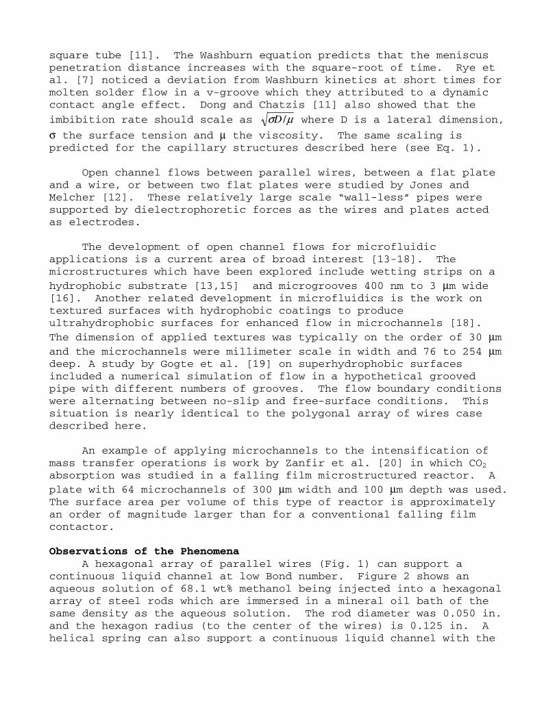
A hexagonal array of parallel wires (Fig. 1) can support a continuous liquid channel at low Bond number. Figure 2 shows an aqueous solution of 68.1 wt% methanol being injected into a hexagonal array of steel rods which are immersed in a mineral oil bath of the same density as the aqueous solution. The rod diameter was 0.050 in. and the hexagon radius (to the center of the wires) is 0.125 in. A helical spring can also support a continuous liquid channel with the
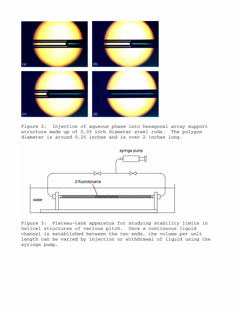
advantage that the stability of the system can be adjusted by simply changing the pitch of the spring [1]. Figure 4(a) shows an example of a continuous liquid channel supported in a 1/4 in. diameter spring. The field of view in Fig. 4 shows only a small portion of the 10 in. long liquid channel. In this case the liquid in the spring is 2-fluorotoluene and the bath is pure water. The bath is held at 26.5 °C at which temperature the two liquids have the same density. Figure 4 also illustrates the observation that the capillary surface is stable over a limited range of volumes and therefore pressures. It has also been observed that a continuous water channel can be established in a 1/8 in. diameter horizontal spring surrounded by air provided the pitch of the spring is small enough. Hydrostatic Stability
The static stabililty of supported capillary pipes at zero Bond number is expected to depend on the contact angle, several dimensionless geometric factors characterizing the support, and the non dimensional volume per unit length of liquid in the structure. The geometric factors include the number of wires, the ratio Rw/Rp , where Rw is the wire radius and Rp is the radius of the spring or polygonal array (to the center of the wire) and, in the case of helices, the dimensionless pitch (L/Rp). Rp will also be referred to as the radius of the supported capillary pipe. The static stability is predicted by computing the Laplace pressure in an infinite length
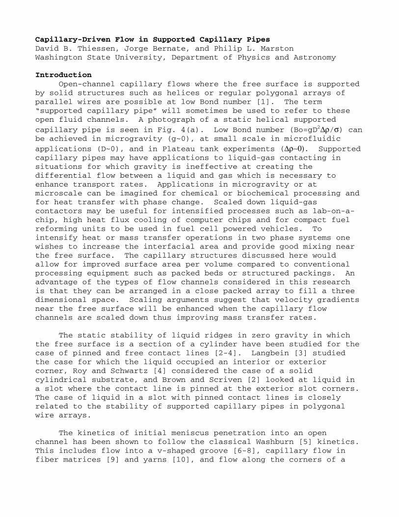
Figure 1: Axial view of hexagonal wire support and bridged liquid surfaces. The arrow indicates the camera viewpoint for the images in Fig. 2.
(a) (b)
(c) (d)
Figure 2: Injection of aqueous phase into hexagonal array support structure made up of 0.05 inch diameter steel rods. The polygon diameter is around 0.25 inches and is over 2 inches long.
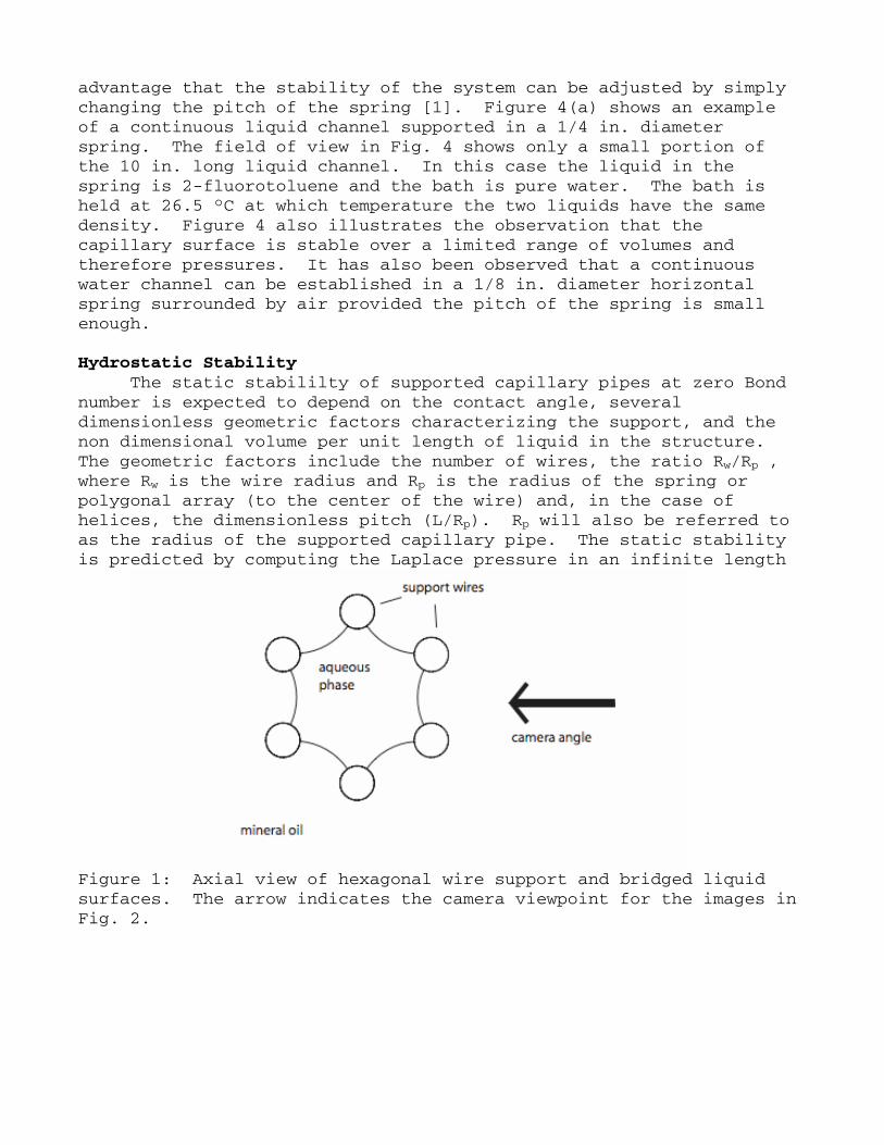
Figure 3: Plateau-tank apparatus for studying stability limits in helical structures of various pitch. Once a continuous liquid channel is established between the two ends, the volume per unit length can be varied by injection or withdrawal of liquid using the syringe pump.
(a) (c)
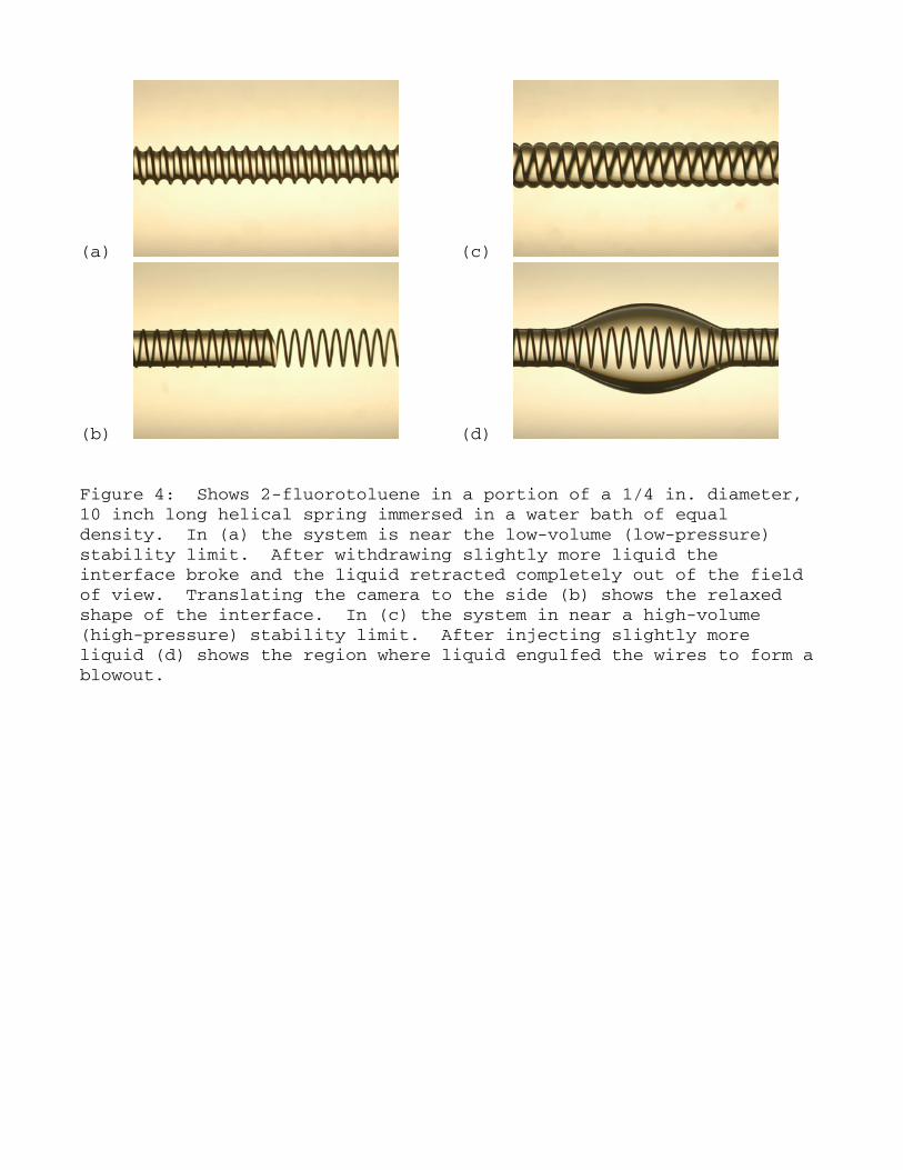
(b) (d) Figure 4: Shows 2-fluorotoluene in a portion of a 1/4 in. diameter, 10 inch long helical spring immersed in a water bath of equal density. In (a) the system is near the low-volume (low-pressure) stability limit. After withdrawing slightly more liquid the interface broke and the liquid retracted completely out of the field of view. Translating the camera to the side (b) shows the relaxed shape of the interface. In (c) the system in near a high-volume (high-pressure) stability limit. After injecting slightly more liquid (d) shows the region where liquid engulfed the wires to form a blowout.
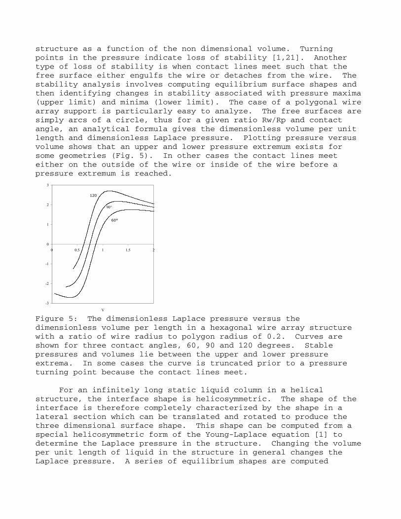
structure as a function of the non dimensional volume. Turning points in the pressure indicate loss of stability [1,21]. Another type of loss of stability is when contact lines meet such that the free surface either engulfs the wire or detaches from the wire. The stability analysis involves computing equilibrium surface shapes and then identifying changes in stability associated with pressure maxima (upper limit) and minima (lower limit). The case of a polygonal wire array support is particularly easy to analyze. The free surfaces are simply arcs of a circle, thus for a given ratio Rw/Rp and contact angle, an analytical formula gives the dimensionless volume per unit length and dimensionless Laplace pressure. Plotting pressure versus volume shows that an upper and lower pressure extremum exists for some geometries (Fig. 5). In other cases the contact lines meet either on the outside of the wire or inside of the wire before a pressure extremum is reached.
-3
-2
-1
0
1
2
3
0 0.5 1 1.5 2
V
120
90°
60°
Figure 5: The dimensionless Laplace pressure versus the dimensionless volume per length in a hexagonal wire array structure with a ratio of wire radius to polygon radius of 0.2. Curves are shown for three contact angles, 60, 90 and 120 degrees. Stable pressures and volumes lie between the upper and lower pressure extrema. In some cases the curve is truncated prior to a pressure turning point because the contact lines meet.
For an infinitely long static liquid column in a helical structure, the interface shape is helicosymmetric. The shape of the interface is therefore completely characterized by the shape in a lateral section which can be translated and rotated to produce the three dimensional surface shape. This shape can be computed from a special helicosymmetric form of the Young-Laplace equation [1] to determine the Laplace pressure in the structure. Changing the volume per unit length of liquid in the structure in general changes the Laplace pressure. A series of equilibrium shapes are computed
mapping out an equilibrium branch in pressure-volume space. Extreme values in the pressure represent changes in stability. Results for the stability limits from equilibrium branches can be compiled into a stability envelope where the stability boundaries are mapped out in terms of volume and the non dimensional pitch, L, of the helix. For a given pitch, there is an upper and lower stable volume unless the pitch is beyond a critical value for which no stable solutions exist. For a very tight pitch (L going to zero) the range of stable volumes shrinks toward zero, however, the corresponding range of stable pressures diverges. Basically in this limit the collapsed spring becomes a solid-walled pipe.
Static stability has been demonstrated for a wide range of volumes in Plateau tank studies with helical supports. A schematic of the Plateau tank appartus is shown in Fig. 3. The fluid channel is easily established by simply injecting liquid from one or both ends of the structure until a continuous channel bridges the two injection ports. After a continuous channel is established the volume per unit length in the structure can be carefully adjusted using the syringe pump in order to measure stability limits. Figure 4(a) shows a structure near a minimum volume stability limit and Fig. 4(b) shows the meniscus shape after breakage, while Fig. 4(c) shows a structure near a maximum volume stability limit and Fig. 4(d) shows the subsequent wire support engulfment. The outer diameter of the spring in these experiments was 0.25 in. and the spring length was 10 inches. The liquid in the support was 2-fluorotoluene and the bath liquid was pure water held at 26.5 °C, the isodensity temperature for the 2-fluorotoluene/water system. The range of pressures which can be sustained in the supported capillary pipe for a given support geometry are dictated by these low and high volume limits. This then also dictates how much pressure driving force can be applied between the two ends of the structure to drive a flow. Flow Characteristics
To be useful in potential applications, it must be possible to establish the fluid channel by simply injecting liquid into one end of the support structure such that the meniscus pentrates the structure over large distances. This requires that the supported capillary structure be stable over a range of pressures. To drive the penetration flow, the pressure at the entrance of the structure must be maintained above the pressure in the liquid at the advancing meniscus. It is expected that a form of the Washburn-Lucas equation will apply here, where the penetration distance, l, goes as time to the one-half power.
l2 = 2QσRPΔP
Aμ⎛
⎝ ⎜
⎞
⎠ ⎟ t (1)
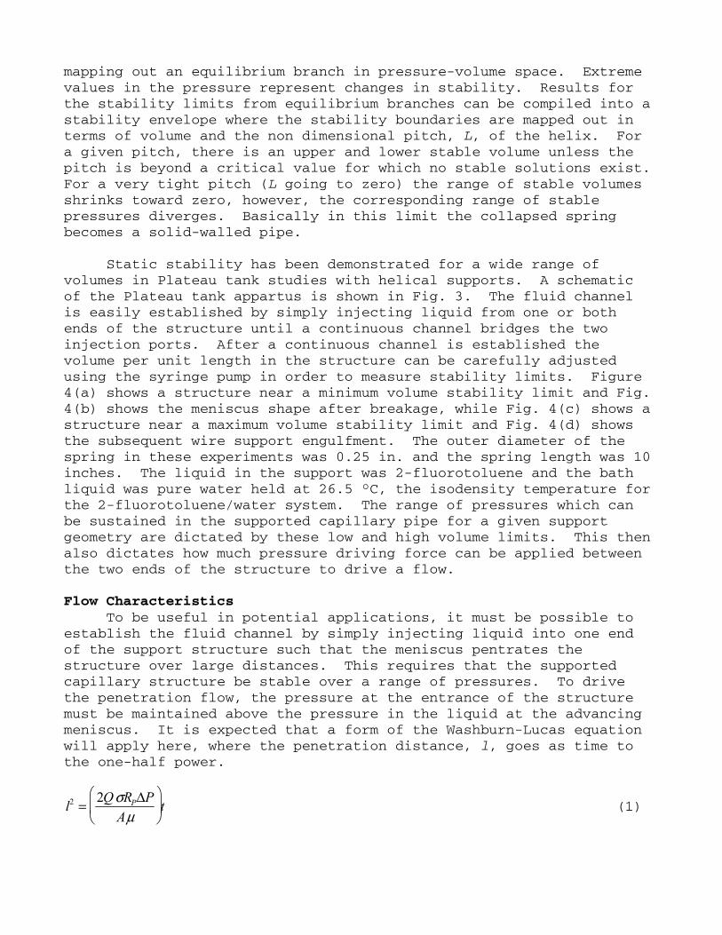
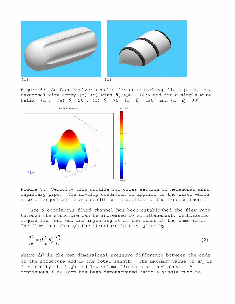
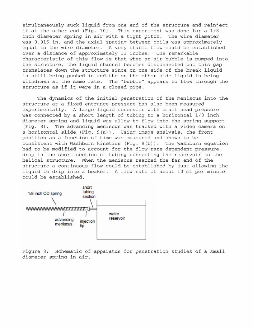
Here RP is the radius of the capillary pipe, σ is surface tension, μ is kinematic viscosity, A a non dimensional cross sectional area of liquid, and ΔP the dimensionless pressure driving force. In the above equation, Q is the non dimensional flow rate per unit pressure gradient, which is determined from a finite element solution to Poisson’s equation for the given geometry with no slip boundary conditions on the wires and and zero stress conditions at the free surfaces. The pressure difference between the entrance and the advancing meniscus, ΔP, is limited by stability issues. The pressure at the entrance is limited by the upper pressure stability limit. The pressure at the advancing meniscus depends on the contact angle the liquid makes with the wire. The program Surface Evolver has been used to compute the shapes and Laplace pressure in finite length liquid slugs in hexagonal arrays and helical structures as shown in Fig. 6. Figure 6 (a)-(c) shows the change in meniscus shape going from a wetting (a) to a non wetting (c) liquid. The Laplace pressure in such a slug is expected to approach a constant value as the slug length increases. Ignoring dynamic effects on the meniscus, this Laplace pressure should approximate the advancing meniscus pressure. The quantity Q/A was computed for Poiseuille flow in several hexagonal wire array structures using the finite element method. A computed flow profile is shown in Fig. 7. Notice that the flow profile is parabolic near the center as in pipe flow and the free surface velocity is significantly less than the maximum bulk velocity.
(a) (b)
(c) (d) Figure 6: Surface Evolver results for truncated capillary pipes in a hexagonal wire array (a)-(c) with Rw/Rp= 0.1875 and for a single wire helix, (d). (a) θc= 20°, (b) θc= 70° (c) θc= 120° and (d) θc= 90°.
Figure 7: Velocity flow profile for cross section of hexagonal array capillary pipe. The no-slip condition is applied to the wires while a zero tangential stress condition is applied to the free surfaces.
Once a continuous fluid channel has been established the flow rate through the structure can be increased by simultaneously withdrawing liquid from one end and injecting it at the other at the same rate. The flow rate through the structure is then given by
dVdt
= Q σμ
Rp3 ΔPL
LT
(2)
where ΔPL is the non dimensional pressure difference between the ends
of the structure and LT the total length. The maximum value of ΔPL is dictated by the high and low volume limits mentioned above. A continuous flow loop has been demonstrated using a single pump to
simultaneously suck liquid from one end of the structure and reinject it at the other end (Fig. 10). This experiment was done for a 1/8 inch diameter spring in air with a tight pitch. The wire diameter was 0.016 in. and the axial spacing between coils was approximately equal to the wire diameter. A very stable flow could be established over a distance of approximately 11 inches. One remarkable characteristic of this flow is that when an air bubble is pumped into the structure, the liquid channel becomes disconnected but this gap translates down the structure since on one side of the break liquid is still being pushed in and the on the other side liquid is being withdrawn at the same rate. The “bubble” appears to flow through the structure as if it were in a closed pipe.
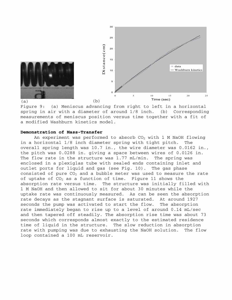
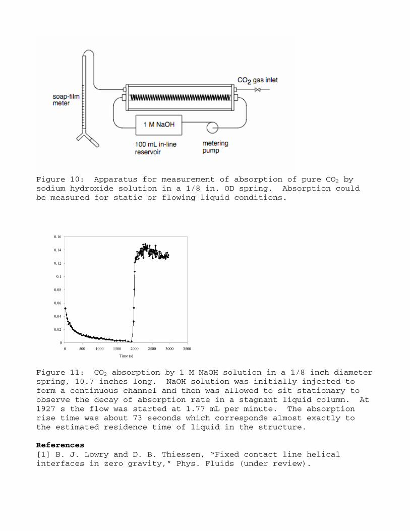
The dynamics of the initial penetration of the meniscus into the structure at a fixed entrance pressure has also been measured experimentally. A large liquid reservoir with small head pressure was connected by a short length of tubing to a horizontal 1/8 inch diameter spring and liquid was allow to flow into the spring support (Fig. 8). The advancing meniscus was tracked with a video camera on a horizontal slide (Fig. 9(a)). Using image analysis, the front position as a function of time was measured and shown to be consistent with Washburn kinetics (Fig. 9(b)). The Washburn equation had to be modified to account for the flow-rate dependent pressure drop in the short section of tubing connecting the reservoir to the helical structure. When the meniscus reached the far end of the structure a continuous flow could be established by just allowing the liquid to drip into a beaker. A flow rate of about 10 mL per minute could be established.
Figure 8: Schematic of apparatus for penetration studies of a small diameter spring in air.
(a) (b)
0
5
10
15
20
25
30
0 5 10 15 20 25
Time (sec)D
i s t
a n
c e
( c
m )
dataWashburn kinetics
Figure 9: (a) Meniscus advancing from right to left in a horizontal spring in air with a diameter of around 1/8 inch. (b) Corresponding measurements of meniscus position versus time together with a fit of a modified Washburn kinetics model. Demonstration of Mass-Transfer
An experiment was performed to absorb CO2 with 1 M NaOH flowing in a horizontal 1/8 inch diameter spring with tight pitch. The overall spring length was 10.7 in., the wire diameter was 0.0162 in., the pitch was 0.0288 in. giving a space between wires of 0.0126 in. The flow rate in the structure was 1.77 mL/min. The spring was enclosed in a plexiglas tube with sealed ends containing inlet and outlet ports for liquid and gas (see Fig. 10). The gas phase consisted of pure CO2 and a bubble meter was used to measure the rate of uptake of CO2 as a function of time. Figure 11 shows the absorption rate versus time. The structure was initially filled with 1 M NaOH and then allowed to sit for about 30 minutes while the uptake rate was continuously measured. As can be seen the absorption rate decays as the stagnant surface is saturated. At around 1927 seconds the pump was activated to start the flow. The absorption rate immediately began to rise up to a level of around 0.14 mL/sec and then tapered off steadily. The absorption rise time was about 73 seconds which corresponds almost exactly to the estimated residence time of liquid in the structure. The slow reduction in absorption rate with pumping was due to exhausting the NaOH solution. The flow loop contained a 100 mL reservoir.
Figure 10: Apparatus for measurement of absorption of pure CO2 by sodium hydroxide solution in a 1/8 in. OD spring. Absorption could be measured for static or flowing liquid conditions.
0
0.02
0.04
0.06
0.08
0.1
0.12
0.14
0.16
0 500 1000 1500 2000 2500 3000 3500
Time (s)
Figure 11: CO2 absorption by 1 M NaOH solution in a 1/8 inch diameter spring, 10.7 inches long. NaOH solution was initially injected to form a continuous channel and then was allowed to sit stationary to observe the decay of absorption rate in a stagnant liquid column. At 1927 s the flow was started at 1.77 mL per minute. The absorption rise time was about 73 seconds which corresponds almost exactly to the estimated residence time of liquid in the structure. References [1] B. J. Lowry and D. B. Thiessen, “Fixed contact line helical interfaces in zero gravity,” Phys. Fluids (under review).
[2] R. A. Brown and L. E. Scriven, “On the multiple equilibrium shapes and stability of an interface pinned on a slot,” J. Colloid Interface Sci. 78, 528-542 (1980). [3] D. Langbein, "The Shape and Stability of Liquid Menisci at Solid Edges," J. Fluid Mech. 213, 251-265 (1990). [4] R. V. Roy and L. W. Schwartz, “On the stability of liquid ridges,” J. Fluid Mech. 391, 293-318 (1999). [5] E. W. Washburn, "The Dynamics of Capillary Flow," Phys. Rev., 17(3), 273-283 (1921). [6] L. A. Romero and F. G. Yost, “Flow in an open channel capillary,” J. Fluid Mech. 322, 109-129 (1996). [7] R. R. Rye, F. G. Yost, and J. A. Mann, "Wetting Kinetics in Surface Capillary Grooves," Langmuir, 12, 4625-4627 (1996). [8] F. G. Yost, R. R. Rye, and J. A. Mann, “Solder wetting kinetics in narrow V-grooves,” Acta Mat. 45, 5337-5345 (1997). [9] A. Takahashi, M. Haggkvist, and T. Q. Li, “Capillary penetration in fibrous matrices studied by dynamic spiral magnetic resonance imaging,” Phys. Rev. E 56, 2035-2042 (1997). [10] A. Perwuelz, P. Mondon, and C. Caze, “Experimental study of capillary flow in yarns,” Textile Res. J. 70, 333-339 (2000). [11] M. Dong and I. Chatzis, "The Imbibition and Flow of a Wetting Liquid along the Corners of a Square Capillary Tube," J. Colloid Interface Sci. 172, 278-288 (1995). [12] T. B. Jones and J. R. Melcher, "Dynamics of Electromechanical Flow Structures," Phys. Fluids 16, 393-400 (1973). [13] H. Gau, S. Herminghaus, P. Lenz, and R. Lipowsky, "Liquid Morphologies on Structured Surfaces: From Microchannels to Microchips," Science 283, 46-49 (1999). [14] A. Valencia, M. Brinkmann, and R. Lipowsky, “Liquid Bridges in Chemically Structured Slit Pores,” Langmuir 17, 3390-3399 (2001). [15] P. L. Lam, K. J. Wynne, and G. E. Wnek, “Surface-Tension-Confined Microfluidics,” Langmuir 18, 948-951 (2002). [16] R. Seemann, M. Brinkmann, E. J. Kramer, F. F. Lange, and R. Lipowsky, “Wetting morphologies at microstructured surfaces,” PNAS 102, 1848-1852 (2005). [17] S. Bouaidat, O. Hansen, H. Bruus, C. Berendsen, N. K. Bau-Madsen, P. Thomsen, A. Wolff, and J. Jonsmann, “Surface-directed capillary system; theory, experiments and applications,” Lab Chip (8), 827-836 (2005). [18] J. Ou, B. Perot, and J. P. Rothstein, “Laminar drag reduction in microchannels using ultrahydrophobic surfaces,” Phys. Fluids 16, 4635-4643 (2004). [19] S. Gogte, P. Vorobieff, R. Truesdell, A. Mammoli, F. van Swol, P. Shah, and C. J. Brinker, “Effective slip on textured superhydrophobic surfaces,” Phys. Fluids 17, 0511701 (2005). [20] M. Zanfir, A. Gavriilidis, Ch. Wille, and V. Hessel, “Carbon Dioxide Absorption in a Falling Film Microstructured Reactor: Experiments and Modeling,” Ind. Eng. Chem. Res. 44, 1742-1751 (2005).
[21] B. J. Lowry and P. H. Steen, "Capillary surfaces: stability from families of equilibria with application to the liquid bridge," Proc. R. Soc. Lond. A 449, 411-439 (1995).