48
May 2007 Printed versions of this manual are uncontrolled.
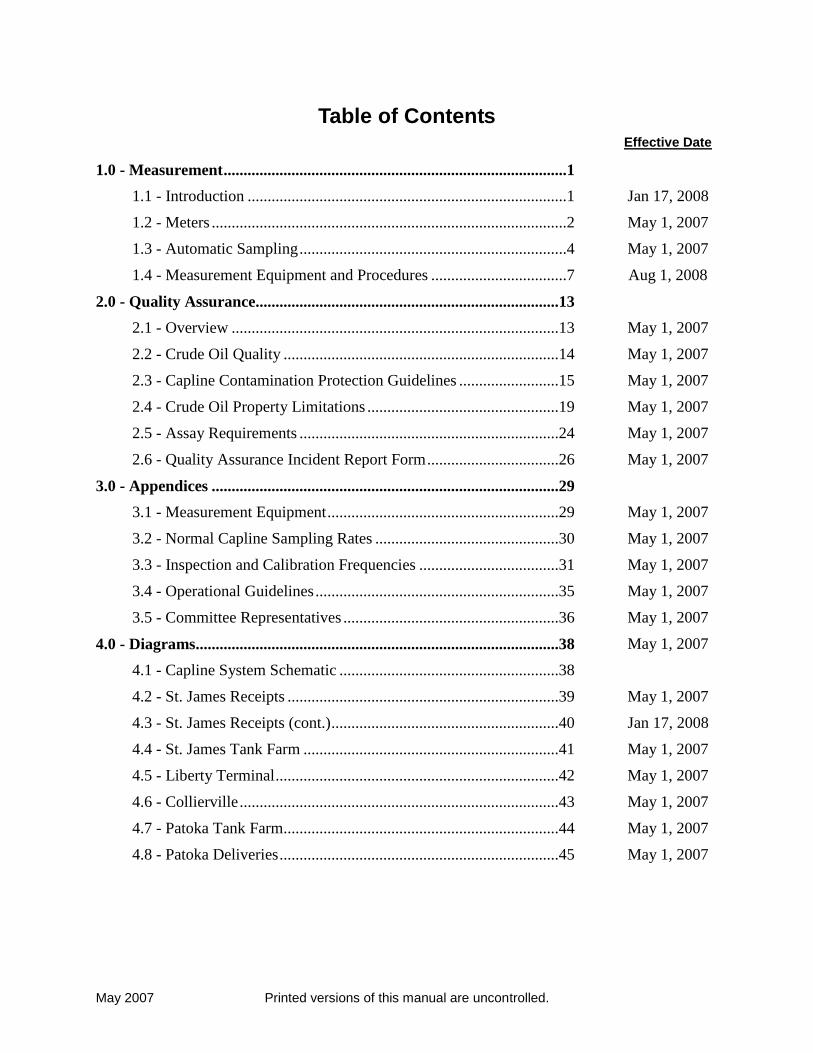
Table of Contents Effective Date
1.0 - Measurement ......................................................................................1
1.1 - Introduction ................................................................................1
1.2 - Meters .........................................................................................2
1.3 - Automatic Sampling ...................................................................4
1.4 - Measurement Equipment and Procedures ..................................7
2.0 - Quality Assurance............................................................................13
2.1 - Overview ..................................................................................13
2.2 - Crude Oil Quality .....................................................................14
2.3 - Capline Contamination Protection Guidelines .........................15
2.4 - Crude Oil Property Limitations ................................................19
2.5 - Assay Requirements .................................................................24
2.6 - Quality Assurance Incident Report Form .................................26
3.0 - Appendices .......................................................................................29
3.1 - Measurement Equipment ..........................................................29
3.2 - Normal Capline Sampling Rates ..............................................30
3.3 - Inspection and Calibration Frequencies ...................................31
3.4 - Operational Guidelines .............................................................35
3.5 - Committee Representatives ......................................................36
4.0 - Diagrams...........................................................................................38
4.1 - Capline System Schematic .......................................................38
4.2 - St. James Receipts ....................................................................39
4.3 - St. James Receipts (cont.) .........................................................40
4.4 - St. James Tank Farm ................................................................41
4.5 - Liberty Terminal .......................................................................42
4.6 - Collierville ................................................................................43
4.7 - Patoka Tank Farm.....................................................................44
4.8 - Patoka Deliveries ......................................................................45
Jan 17, 2008
May 1, 2007
May 1, 2007
Aug 1, 2008
May 1, 2007
May 1, 2007
May 1, 2007
May 1, 2007
May 1, 2007
May 1, 2007
May 1, 2007
May 1, 2007
May 1, 2007
May 1, 2007
May 1, 2007
May 1, 2007
May 1, 2007
Jan 17, 2008
May 1, 2007
May 1, 2007
May 1, 2007
May 1, 2007
May 1, 2007

May 2007 Printed versions of this manual are uncontrolled.
THIS PAGE INTENTIONALLY BLANK
May 2007 Printed versions of this manual are uncontrolled. Page 1
1.0 - Measurement
1.1 - Introduction
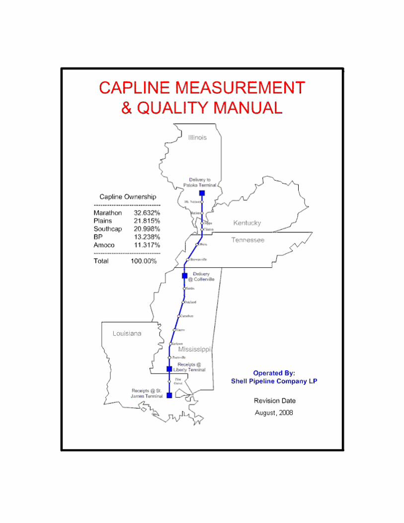
In accordance with the Capline agreement, meters are used for custody transfer measurement of
all receipts into and deliveries out of the Capline system. Crude oil is transported by the system
from tankers, barges, and pipelines of participants or connecting carriers.
Many of the measurement policies and procedures located within this manual have been based
upon the American Petroleum Institute’s Manual of Petroleum Measurements Standards (API
MPMS). The MPMS sets forth industry standards and drives expectations for custody transfer
measurement. For guidance on measurement issues not specifically addressed herein, the user
shall defer to the specific Site Measurement Plan in the Connection Agreement, the Shell
Pipeline Measurement Manual, and finally to the appropriate MPMS standard. CAPLINE
attempts to meet or exceed all MPMS requirements, however, reserves the right to deviate from
the API MPMS when necessary. Variances require the unanimous approval from the owners
represented through the CAPLINE Measurement and Quality Committee, and all approved
variances are documented within this manual.
Custody transfer meters are located at St. James, Liberty, Collierville, and Patoka. A
combination of turbine meters and positive displacement meters are provided by the system and
by connecting carriers for the receipt of crude oil from tankers, barges, and pipelines of
participants. As an additional check on measurement within the system, turbine meters are
provided at St. James and Liberty to measure all receipts into the mainline and at Patoka to
measure all deliveries out of the mainline. Although the mainline turbine meters are not
typically used for primary custody transfer measurement, they are maintained at a custody
transfer level and constitute the secondary points of measurement. One exception is the use of
the St. James mainline meters for primary custody transfer when originating from ART and
Sugarland. The final point of measurement is the delivery meters at Patoka. Positive
displacement and Helical Turbine meters are used at Patoka. Turbine meters are used at
Collierville for custody transfer deliveries from the mainline at these locations.
To insure accurate measurement across St James terminal, opening and closing tank gauges are
recorded for each batch of crude oil stored in a tank or tanks. By applying any fluctuation (e.g.
float/relief sys.) in tank inventory to receipts into St James or to deliveries out of St James, all
custody meter transactions are checked. The connecting carrier records Collierville tank gauges.
In the event of an equipment malfunction (such as preamplifiers, counter, and/or flow computer
failures) during custody transfer; the storage tanks involved are hand gauged. The ticket is
written based on mainline meters and tank inventory change at St. James and on tank gauges at
Liberty, and Collierville.
At Patoka, in cases of electronic failure, the adjustment tickets are written using mechanical
totalizer readings on meter head compared to gross totalizer reading on metering electronics. In
cases of mechanical failure of a meter, Patoka will write the adjustment ticket based on the
gauge/inventory change procedure.
May 2007 Printed versions of this manual are uncontrolled. Page 2
1.2 - Meters
1.2.1 - Meter Proving
Meters are proved locally. Local control panels at St. James, Liberty, Collierville, and Patoka
include mimic piping with indicating lights so that valve alignment can be checked and
individual meters proved from the panel. The OMNI flow controller will check for a seal
indication. It will abort the proving if it does not detect a seal.
1.2.2 - Procedure for Meter Factor Determination
Mechanical displacement pipe provers are utilized by the system. A meter factor shall be
determined from the average of five proving runs out of six consecutive proving runs that agree
within 0.05 percent. If this agreement is not achieved within 10 consecutive proving runs, the
proving is terminated and an investigation is made to determine the problem. Another,
investigation will be made to determine the cause of the change if the resulting meter factor is
outside of the acceptable range on the Meter Factor Control Chart for that meter and commodity.
1.2.3 - Prover Calibration and Recalibration
The provers were originally calibrated using the water draw method to determine the actual
volume. Recalibrations are performed in the same manner.
The National Institute of Standards and Technology (formerly National Bureau of Standards)
certifies the volumes of the test measures used in this process. Participating parties are invited to
witness each prover calibration or recalibrations and all parties present sign the calibration
certificate.
1.2.3.a - Prover Recalibration Intervals
A pipe prover should be recalibrated before the volume changes by more than 0.04 percent.
Under normal operating conditions, a prover's volume will change due to wear in a fairly
uniform manner with time, and historical data can be used as a basis for determining the
frequency of recalibration for each prover.
Historical data for all Capline provers indicate that an interval of no more than five years will be
adequate to insure that the volume has not changed more than 0.04%. If a prover's volume does
deviate by more than 0.04%, that prover will be recalibrated on a more frequent basis as
determined by the Capline Measurement and Quality Committee.
May 2007 Printed versions of this manual are uncontrolled. Page 3
1.2.3.b - Test For A Good Calibration
If the new volume measured by recalibration changes more than 0.02 percent from the previous
volume and history indicates the volume should not have changed more than 0.02 percent, run
another check calibration or inspect the prover and ancillary equipment, or both. The new
volume may be accepted if the prover is in good order and the check calibration substantiates the
change in volume.
It is not uncommon for a relatively new prover's second volume to differ substantially from the
initial calibration. This may be due to excessive wear during the break-in period, or to a poor
initial calibration that was undetected due to lack of history.
The water draw method for prover calibration shall occur a minimum of every five (5) years
from the date of the last calibration, or immediately after any alteration to the measurement
section or switches. Special recalibrations shall be required if switches are changed or if a prover
exhibits erratic performance for any reason. For example, if there is evidence of coating flaking
off, the prover must be repaired and recalibrated. If an immediate water draw is impractical, e.g.
at Patoka during the winter, a carefully matched switch change may be made until a water draw
can be performed. If the draw volume changes more than 0.02%, corrections will be made on all
tickets written after the switch change.
Capline uses Bi-directional and Uni-directional provers. The Bi-directional prover is the four-
way valve type interchange and the Uni-directional provers are the dual-cup type seal or the ram
type interchange seal. The design of the sealing section must be considered when performing
water draw calibrations.
The dual-cup type seals create differential pressure that is monitored with pressure gauges. It is
recommended that the working gauges be replaced with traceable 1-psig increment gauges when
performing a calibration. If the cavity is opened to atmosphere, the cups may flex when pressure
changes occur when switching cans, and force some water out of the cavity, creating the illusion
of a leak. The volume established at recalibration would be the volume used from that date
until the next recalibration.
1.2.3.c - Meter Factor Control Charts and Records
Meter factor control charts and/or records (API MPMS Chapter 13 Section 2 Methods of
Evaluating Meter Proving Data) will be kept on all meters on Capline by the appropriate
personnel responsible for proving the meters so that they are available to them, and to Capline
supervisors, carriers, and/or shippers for ready reference. Control Charts and records will be
maintained in the Prove-It proving program database.
1.2.3.d - Patoka
Positive displacement meters and helical turbine meters are used for deliveries out of Patoka.
Each meter is proven on each batch that is delivered. Samples are collected using an in-line
sampling arrangement equipped with static mixer and held until the delivery is completed. Each
sample processed for S&W and gravity may be witnessed by a representative from the carrier or
operator receiving the crude oil or a waiver is used if none are present.

May 2007 Printed versions of this manual are uncontrolled. Page 4
1.3 - Automatic Sampling
Samples are collected (see Appendix 2) for each batch of crude oil received or delivered by
Capline. These samples are collected either by samplers installed directly in the pipeline or by
slip-stream samplers. All automatic sampling systems will be built and tested in accordance with
API MPMS 8.2. Unless specifically designated below, the procedures used for all other
sampling systems will follow accepted API procedures. All Sample Systems should be verified
per API MPMS Chapter 8.2 to assure the samples are representative of the crude being measured.
Crude oil samples received across the docks are gathered and held in their respective sample
collection containers until tankers or barges finish unloading. When the samples are processed,
representatives of involved participants may witness the gravity and S&W tests. All receipts and
deliveries are based on Gross Standard Volume (gross 60°F) barrels with deductions for
sediment and water based on the above samples.
1.3.1 - St. James Dock No. 1
Dock 1 has two loading arms. On the dock, the two loading arms are manifold into a single line
containing a static mixer and two sample probes. Each sample probe delivers samples to its own
dedicated sample collection container.
Dual sample systems are in place on dock 1 for redundancy purposes only. One of these
systems is stenciled as "Primary" and the other is labeled "Secondary".
Upon completion of each receipt, and barring a known physical failure in the primary sampling
system, only the crude sample contained in the "primary" sample collection container will be
worked for gravity and S&W determination for that transaction. Also, no mixing will be
performed nor tests run on the sample contained in the "secondary" (redundant) container.
Known Physical Failures are defined as:
1) A sampler malfunction, which is exhibited by:
(a) A full Sample Pot
(b) An inadequate sample pot volume as determined by the operator for the volume run.
2) A sample pot mixer malfunction that is exhibited by noncompliance with API Chapter 10.4
procedures.
3) Any other known physical failure as defined by the operator.
In the event of a known physical failure of the primary sampling system during the transaction,
the primary container will be purged without mixing or testing, and gravity and S&W
determination will be based on the sample collected by the secondary system.
After mixing the composite sample in the primary or secondary container, the samples are
withdrawn for the gravity determination and S&W analysis.
The sampling systems are drained after an acceptable S&W determination has been made.

May 2007 Printed versions of this manual are uncontrolled. Page 5
Sampler performance is monitored by attendants to ensure that a representative sample is
obtained.
In the event that both the primary and secondary samplers fail during a discharge, the S&W
volumes for the discharge will be determined through negotiation.
1.3.2 - St. James Dock No. 2, 3 and 4 Out of Service
There are no sampling equipment installed or dual sampling procedures in place or existing.
1.3.3 - API Gravity and S&W Determination
The purpose of this section is to define the procedures that will be used to determine API Gravity
and Sediment & Water.
1.3.3.a - API Gravity
API Gravity - API Gravity will be determined using API MPMS Chapter 9 Section 3, Standard
Test Method for Density, Relative Density and API Gravity of Crude Petroleum Products by
Thermohydrometer Method.
1.3.3.b - Centrifuge Sediment & Water (S&W)
Centrifuge Sediment & Water (S&W) - S&W will be determined in most cases using API
MPMS Chapter 10 Section 4, Determination of Water and/or Sediment in Crude Oil by the
Centrifuge Method (Field Procedure.) This procedure normally will be followed using the
equipment and solvents described below, however, changes may be made as long as they are still
in accordance with the API procedure. Any desired changes that are not in accordance with the
procedure will require approval by the Capline Measurement and Quality Committee.
1) Tubes - Two 100 mL (200 parts) cone-shaped calibrated and verified centrifuge tubes are
used to process the samples.
2) Solvents and Demulsifiers - Stoddard (or Stoddard-type) solvent is used for more routine
applications, while water saturated Toluene solvent is used for those crude oils that do not
respond to tests performed with Stoddard solvent. When acceptable results cannot be
obtained using Stoddard solvents, samples must then be tested using either toluene solvent or
other methods. Local measurement personnel should be able to advise whether Stoddard
solvent or use of other methods are required. Currently, DMO 46x is used as a demulsifier.
Other demulsifiers may be tested and used as needed.
1.3.3.c - Karl Fischer Water
Karl Fischer Water - With approval of the Capline Measurement and Quality Committee, water
can be determined using API MPMS Chapter 10 Section 9, Standard Test Method for Water in
Crude Oils by Coulometric Karl Fischer Titration. If this method is used, an alternate API
MPMS method will be used for sediment determination.
May 2007 Printed versions of this manual are uncontrolled. Page 6
1.3.3.d - Referee Method for S&W
Referee Method for S&W - In the event of a dispute, the referee methods for S&W will be API
MPMS Chapter 10 Section 2, Determination of Water in Crude Oil by Distillation and API
MPMS Chapter10 Section 1, Standard Test Method for Sediment in Crude Oils and Fuel Oils by
the Extraction Method unless the interested parties agree on alternative testing.

May 2007 Printed versions of this manual are uncontrolled. Page 7
1.4 - Measurement Equipment and Procedures
1.4.1 - St. James Docks
A spreadsheet of current measurement equipment is included in the appendix of this manual.
Turbine meters are used for measurement on Dock I. Each meter used during the unloading of a
tanker is proved approximately one-hour after start of unloading. A 22-inch unidirectional
prover is used to prove the three 10-inch helical turbine meters on Dock I. The Dock 2 meters
have been activated for use in measurement of cargos unloaded into the Plains St James tank
farm. The Dock 1 unloading arms and sampling systems are used when unloading into the
Plains St James tank farm.
1.4.2 - Custody Volume Determination
Procedures for cargos unloaded into shore tankage at St. James docks:
1) Verify the line fill prior to unloading using the procedure below:
Capline Docks Line Fill Verification Procedure.pdf
2) Prove the dockside meters after one-hour of the unloading.
2) If the meter factor is within ± 0.0025 of the previous factor of the same crude type for the
meter, the factor shall be used for the run ticket.
NOTE: When a meter receiving a new crude type, or an infrequently handled crude type
(one that has not been handled in six months) is proved, the factor obtained shall be
considered the result of an initial proving and used for ticketing purposes. In such a case, an
additional confirmation proving must be made later in the batch.
4) If the meter factor is within ± 0.0025 of the previous factor of the same crude type for the
meter, the factor shall be used for the run ticket.
(a) The dockside gross 60°F metered volume shall be compared with the sum of the
deliveries via the mainline meters to the mainline plus/minus the change in tank
inventory at low gauge (filling through emptying).
(b) If the dockside gross 60°F metered volume is within ± 0.25 percent of the deliveries to
the mainline and the change in the tank inventory, the dockside gross 60° F volume shall
be used on the run ticket.
(c) If the dockside gross 60°F volume deviation is greater than 0.25 percent from the
deliveries to the mainline and the change in tank inventory, the latter shall be used for the
run tickets.
5) When there is a temperature transmitter failure on a meter run(s), an adjustment is needed for
May 2007 Printed versions of this manual are uncontrolled. Page 8
the volumes that went through the affected meter(s) using the average temperatures on the
other meter runs.
6) In the event the mainline meters fail during their required service as custody transfer, the
cargo volume shall be determined by secondary measurement.
7) The dockside S&W determination shall always be used with either the primary or secondary
gross 60°F measurement methods for the run tickets and "net 60°F barrels" calculations.
Cargo volumes are determined with the above guidelines and will be reviewed by the operator
upon the carrier’s request and presentation of reasonable evidence of mismeasurement.
1.4.3 - Secondary Measurement
To insure continuous measurement across St James terminal, opening and closing tank gauges
are recorded for each batch of crude oil stored in a tank or tanks. By applying any fluctuation in
tank inventory to receipts into the mainline or to deliveries out of the mainline, all custody
transfer meter transactions are checked. In the event of equipment malfunction (such as
preamplifiers, counters, temperature transmitter/compensator, or meter failure) during the
custody transfer, or a meter factor deviation greater than 0.0025 from the previous meter factor,
secondary measurement will be used to determine volumes.
In the event the St. James mainline meters fail during their required service as secondary
measurement or when a tank is being floated and there is a malfunction, the volume shall be
determined by negotiations between the carrier and the Capline operator.
Upon equipment malfunction or meter failure of one of the St. James landlines (Exxon/Mobil,
Ship Shoal, Shell/Houma, Locap, NuStar, Ergon, ART or Sugarland) the secondary measurement
volume will be determined by negotiations between the carrier and the Capline operator.
1.4.4 - Witnessing of Custody Transfer
1.4.4.a - Witnessing St. James Custody Transfer
Witnessing of custody transfer measurements associated with cargos unloaded at St. James docks
is as follows:
1) Primary measurement procedures may be fully witnessed by carrier and shipper
representatives.
2) If during or immediately after the unloading, the dock meter factors are determined to be out
of tolerance or upon mutually acceptable evidence of mismeasurement (e.g. secondary
measurement) above step in Section 1.4.3 will be checked for possible use as the custody
transfer measurement method.
3) If, prior to unloading, a carrier requests witnessing of secondary measurement of a specific
cargo, the carrier must comply with the following procedures:

May 2007 Printed versions of this manual are uncontrolled. Page 9
(a) Request for witnessing of secondary measurement should be provided by the
applicable carrier at least 48 hours prior to cargo discharge. Shipper requests must be
coordinated through carriers.
(b) Oral requests for witnessing of secondary measurement should be directed to:
Operation Leader – St James Terminal - Shell Pipeline Company LP at phone number
(225) 265-1234.
(c) A written confirmation of each request must be furnished. The carrier and/or shipper
representatives may then witness the manual tank gauges, mainline meter provings,
and meter readings relative to the cargo. The witnesses retain the responsibility to be
present when the normal readings are obtained. Requests for rework of the
readings/observations must be directed to the St. James terminal supervisor and will
be accommodated if conditions and staffing permit.
Written confirmation of requests to witness secondary measurement should be
directed to the following:
Shell Pipeline Company LP
Operation Leader
P. O. Box 63
St James, LA. 70086
4) When secondary measurement is checked and witnessed as mentioned above, the run ticket
volume will be determined with the procedures stated in Sections 1.4.2 (3), 1.4.2 (5),
1.4.2 (6).
1.4.5 - St. James Land Lines
Three helical turbine meters measure crude oil received from Shell/Houma and Ship Shoal. Ship
Shoal delivers through two 10-inch helical turbine meters. Shell uses one 10-inch helical turbine
meter.
A 10-inch helical turbine meter run owned by Exxon/Mobil, and one 8 inch positive
displacement meter (Currently Out-of-Service), owned by NuStar are set to measure receipts
from Exxon/Mobil and NuStar. The NuStar 8-inch is blinded off. A 10-inch turbine meter
owned by Ergon is used to measure receipts from Ergon. The 24-inch bi-directional landline
prover is used to prove all of these meters.
Receipts from NuStar’s Tank Farm at St. James are measured through three (3) 10 inch turbine
meters. A 30-inch bi-directional prover owned by NuStar proves these meters.
Receipts from Sugarland Tank Farm to St. James tankage are measured through three (3) 12-inch
turbine meters. A 24-inch unidirectional prover owned by Shell proves these meters.
Receipts from Acadian River Terminal (ART) Tank Farm to St. James tankage are measured
through two (2) 10-inch helical turbine meters. A 30-inch bi-directional prover owned by Shell
proves these meters.
May 2007 Printed versions of this manual are uncontrolled. Page 10
Receipts from Plains St. James Terminal to St. James tankage or Capline mainline are measured
through three (3) 12-inch and/or two (2) 16-inch helical turbine meters owned by Plains and
located at the Plains St. James Terminal. A 36-inch bi-directional prover owned by Plains
proves these meters.
1.4.6 - Mainline (St. James, Liberty, Patoka)
The 18-inch helical turbine meters with GFC Flow Conditioners on the mainline are designed to
operate over a flow range of 9,000 (@ 30%) to 30,000 (@ 100%) barrels per hour. Three helical
turbine meters are provided at St. James and Patoka and two conventional turbines at Liberty.
A 30-inch unidirectional prover is provided at each of the locations for proving the mainline
meters. Samples are accumulated from the mainline to determine the gravity and S&W content
of each batch of crude. The above -accumulated information is used to write a "non custody
ticket" for every batch received or delivered by the mainline. Although this is not a custody
transaction, the "non custody ticket" provides a method of checking the Loss/Gain at each
location.
1.4.7 - Sugarland and ART Receipts to Capline Mainline
Crude oil receipts from Sugarland and ART to Capline mainline are delivered through the
Capline 18-inch Helical Turbine meters. All custody transfer tickets for Sugarland and ART
deliveries to the Capline Mainline are written using the mainline meters and are proved using the
Capline 30-inch unidirectional prover.
1.4.8 - St. James Locap Receipts
Crude oil receipts from LOCAP are delivered through three (3) 16-inch conventional turbine
meters owned by LOCAP. A 36-inch bi-directional prover is provided to prove the meters. A
Capline ticket is written on all receipts from LOCAP to Capline at St. James. Two automatic
samplers that are located on the LOCAP mainline before the meters collect samples for gravity
and S&W determination.
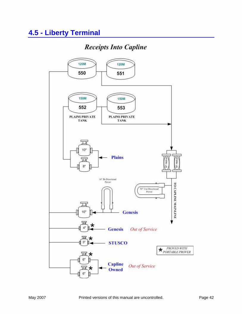
1.4.9 - Liberty
Genesis, Plains, and Shell deliver crude oil to the Capline system at Liberty. The following
positive displacement meters (PD) are used to measure receipts into Liberty:
1.4.9.a - Liberty Meters
1) Two (2) 6-inch - System-owned (inactive)
2) One (1) 4-inch - Genesis-owned
3) One (1) 10-inch - Genesis owned
4) One (1) 8-inch - Plains-owned
May 2007 Printed versions of this manual are uncontrolled. Page 11
5) One (1) 10-inch - Plains-owned
6) One (1) 3-inch – Shell-owned
All of these PD meters are non-temperature compensated.
A portable prover proves the two 6-inch System-owned meters (inactive).
Crude oil is received from the Genesis Truck A.C.T. The proving of the 4-inch PD
meter is done by contract and witnessed by SPLC personnel. SPLC personnel perform the
sample analysis.
Crude oil is received from Gensis through a 10-inch PD meter A 16-inch bi-directional
prover is used to prove the 10-inch meter and it is witnessed by SPLC personnel. SPLC
personnel will perform the sample analysis.
A stationary prover proves the two Plains-owned meters. Samples are collected from
Plains deliveries by using a slipstream arrangement with a sample probe that is installed
directly into the line. SPLC personnel prove and perform the sample analysis.
Crude oil is received from the Shell Truck A.C.T. that has a 3-inch positive displacement
meter. SPLC personnel perform the sample analysis. Proving is done by contract and
witnessed by SPLC personnel.
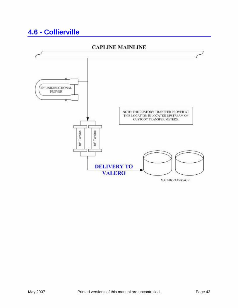
1.4.10 - Collierville
Crude oil deliveries are made from the mainline to Valero tankage through two (2) 18-inch
turbine meters. A 30-inch unidirectional meter proving system proves these meters. Custody is
transferred to the receiving party by utilizing this measurement facility. Measurement volumes
are determined by negotiations between the shipper and Capline operator when there is a meter
failure.
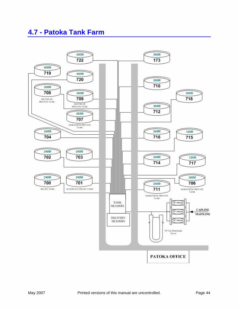
1.4.11 - Patoka
Positive displacement meters and helical turbine meters are used for deliveries out of Patoka.
Each meter is proven on each batch that is delivered. Samples are collected using an in-line
sampling arrangement equipped with static mixer and held until the delivery is completed. Each
sample processed for S&W and gravity may be witnessed by a representative from the carrier or
operator receiving the crude oil or a waiver is used if none are present.

May 2007 Printed versions of this manual are uncontrolled. Page 12
THIS PAGE INTENTIONALLY BLANK
May 2007 Printed versions of this manual are uncontrolled. Page 13
2.0 - Quality Assurance
2.1 - Overview
The CRUDE OIL QUALITY ASSURANCE requirements described in this section are subject to
change and, after initial approval by Capline owners, will be maintained and updated by the
Operator as necessary.
Crude oil quality assurance is the responsibility of each carrier and / or shipper. These
guidelines are designed to aid in the movement of merchantable oil, and to protect the Capline
carriers and / or shippers.
Crude oil quality complaints should be referred to your appropriate carrier. The carrier is
responsible for notifying the Operator’s Manager, Oil Movements. A sample of the Quality
Assurance Customer Complaint Form is included in this Manual and on the Crude Oil Quality
page of http://www.shellpipeline.com/. The carrier is to complete ALL information on this form,
including a detailed explanation of the complaint (occurrences, barrels, economic impact, etc.),
and send it to the Operator as soon as possible.
May 2007 Printed versions of this manual are uncontrolled. Page 14
2.2 - Crude Oil Quality
2.2.1 - Introduction
The Capline Operator reserves the right to periodically sample and test crude oil quality
delivered from the carrier and / or shipper. Sample results will be compared to the representative
assay results furnished prior to connection or nomination of new crude type or to the most recent
Capline assay. If the comparison indicates a significant difference in Crude Oil Properties, and /
or Quality Indicators or contaminated crude oil is found in any receipt, the Capline Operator may
discontinue future shipments at that location. Shipments will not resume until the Capline
Operator’s testing proves the stream to be clean and merchantable.
Two aspects affecting crude oil quality are degradation and contamination:
2.2.2 - Degradation
Degradation occurs during transport due to interfacial mixing, tank bottoms, dock lines, tank
lines and headers, etc. Crude oil degradation can occur in both normal and abnormal flow
situations.
Cargos will be kept segregated. When operationally possible, each crude category will
be moved over like, or the next most similar, dock / dock line, and tank bottom available.
Each crude category will be scheduled into the mainline between similar batches when
operationally possible.
2.2.3 - Contamination
Contamination is addition of an outside ingredient to crude oil, prior to or after entry into the
system, for example, intentional and / or accidental dumping of used lube oils, cleaning solvents,
and chemical by-products. Additives used to enhance production or transportation are not
considered contaminants.
Contaminants can cause damage to refinery processing units, refining catalysts and
pipelines, potentially creating safety and environmental hazards and rendering large
quantities of crude oil Non-merchantable. Traders / suppliers, producers, truckers, barge
operators, gatherers, transporters and refiners MUST assume the responsibility of
preventing crude oil contamination.

May 2007 Printed versions of this manual are uncontrolled. Page 15
2.3 - Capline Contamination Protection Guidelines
2.3.1 - Introduction
The carrier and / or shipper will only deliver for transportation crude oil that complies with the
latest version of the Capline Measurement Equipment and Procedures Manual, exchange
agreements, tariffs, connection agreements and tie-in agreements. Capline has no obligation to
accept or transport contaminated crude oil. If contaminated crude oil enters the Capline System,
the carrier and / or shipper will be held responsible for disposal and for all damages and expenses
incurred in returning the facilities to service.
2.3.2 - Additives
Additives – The amount and ingredients of any additive to be introduced into the Capline
System SHALL be reported in advance of introduction into the system to the Operator’s
Manager, Oil Movements.
Examples of Additives are:
Well treating chemicals
Producing chemicals
Biocides
Corrosion Inhibitors
Paraffin cutters
Hydrate inhibitors
Drag reducing agents
Additives may only be introduced into the Capline System when used in normal production or
transportation operations. They shall not be introduced into merchantable liquid hydrocarbon
streams as a means of disposal of the additive.
At the discretion of the Capline Operator, the carrier and / or shipper may introduce into the
system crude oil that contains hydrate inhibiting additives including, but not limited to, methanol
as a result of production platform shutdowns including, but not limited to, planned or unplanned
maintenance activities or emergency events such as hurricanes. Connecting carriers delivering
such crude to Capline will be responsible for communicating, to the best of their knowledge, the
total methanol concentration to the Capline Operator. The Capline Operator will communicate
the information provided by the incoming carriers to the outbound connecting carriers via
Capline outbound schedules.
2.3.3 - Slops
Slops - Hydrocarbon mixtures usually associated with tank cleaning operations that would result
in greater than 1% Sediment and Water (S&W) in the Capline System SHALL NOT be
introduced into the Capline System.

May 2007 Printed versions of this manual are uncontrolled. Page 16
2.3.4 - Processed Fluids
Processed Fluids - Oil that has been through some modification process may be introducted for
transportation at the discretion of the Operator's Capline Coordinator, Oil Movements. Carrier
and / or shipper must understand that 125,000 Bbls. of processed fluids, after shipment in the
system, may contain as high as 50% crude oil as a consequence of transportation degradation.
General requirements are:
Low aromatics content
Low olefin content
Examples of materials that may contain excess olefins are:
Gasoline (not straight run)
Diesel fuel (not straight run)
Residual fuel oil
Coker by-products
Olefin plant by-products
Cat cracked stocks
Synthetic crude
Upgraded crude
At the discretion of Oil Movements, processed material containing olefins may be introduced
into the Capline System if one of the following conditions can be met:
1. The carrier and / or shipper must have access to proprietary tankage to isolate the
material and must provide sufficient (to be determined by Operator) buffer material to
prevent degradation of other tenders.
2. The carrier and / or shipper must certify that the Bromine Number (ASTM D1159, Test
Method for Bromine Number of Petroleum Distillates and Commercial aliphatic Olefins
by Electrometric Titration) result for the naphtha cut (IBP to 475ºF of the cargo is less
than 2%).
2.3.5 - Waste Materials
Waste materials SHALL NOT be introduced into the Capline System.
Examples of Waste Materials are:
Used lubricating oils
Greases
Lead compounds
Polychlorinated Biphenyls (PCB's)
Cleaning solvents
Chemical plant by-products.
May 2007 Printed versions of this manual are uncontrolled. Page 17
2.3.6 - Organic Chlorides
Organic Chlorides - Oil having measurable organic chlorides SHALL NOT be introduced into
the Capline System. Measurable is defined as not to exceed 1 (one) ppm in the whole crude and
5 (five) ppm in the 400ºF End Point naphtha cut. Organic chlorides do not occur naturally in
crude oil, but appear when outside ingredients, such as chlorinated hydrocarbons are injected
into the systems.
Examples of Organic Chlorides include, but are not limited to:
Halogenated Hydrocarbons
Solvents
PCB’s
Degreasing Agents
Carbon Tetrachloride
Chloroform
Ethylene Dichloride
Dichloroethylene
Methyl Chloride
Ethylene Chloride
Methylene Chloride
"Freon" 113
Vinyl Chloride
1,1 Dichloroethane
Trichloroethane
Tetrachloroethylene
Trichloroethylene
Phosgene
Monochlorobenzene
Chloroprene
Perchloroethylene
May 2007 Printed versions of this manual are uncontrolled. Page 18
2.3.7 - Oxygenated Hydrocarbons
Oxygenated Hydrocarbons - Oil having contaminant, oxygenated hydrocarbons SHALL NOT
be introduced into the Capline System. Some oxygen containing compounds occur naturally in
crude oil and some acceptable additives (examples: hydrate inhibitors, paraffin solvents,
asphaltene dispersants, etc.) contain oxygenated compounds; however, neither chemical plant
output nor gasoline octane enhancers, e.g., MTBE, ETBE and ethanol, occur naturally and are
contaminants.
Examples of Oxygenated Hydrocarbons include, but are not limited to:
Acetone
Alcohols
Aldehydes
Glycols
Ketones
Phenols
Camphor
Esters
Ethers
Carone
May 2007 Printed versions of this manual are uncontrolled. Page 19
2.4 - Crude Oil Property Limitations
2.4.1 - Introduction
Crude oil property limitations are divided into three types. There are limitations that apply to all
crude and limitations that apply based on the grouping of the crude. Specifications for a
particular crude stream are the third type of limitations.
2.4.2 - All Crude
All Crude - The following crude oil property limitations apply to ALL crude oils transported by
Capline.
2.4.2.a - Reid Vapor Pressure
Reid Vapor Pressure (RVP) - (Not to exceed Connecting Carrier requirements or Federal, State
and Local Regulations.)
Crude with an RVP of 8.6 or less may be introduced into the Capline System year-round.
During the winter months, crude with a maximum RVP of 9.6 may be introduced. Crude that is
above these RVP guidelines may be accepted for transportation only after temperatures are
reviewed and approved by Operator’s Manager, Oil Movements. Normally, crude moved in the
winter months may be introduced starting on or after October 1st and SHALL be clear of the
system by April 30th.
2.4.2.b - Pour Point
Pour Point - Crude with a pour point above +35°F SHALL NOT be introduced into the Capline
System in the winter and crude with a pour point above +55°F SHALL NOT be introduced into
the Capline System in the summer. Normally, summer pour point crude may be introduced
starting on or after April 1st and SHALL be clear of the system by September 30th.
Crude nominated for movement across the tanker dock facilities that are not within CAPLINE
pour point limits SHALL be chemically pour point depressed. The delivering carrier and / or
shipper is responsible for coordinating this activity, ensuring the chemical is compatible with
other crude, and causes no contamination. The carrier / shipper assumes responsibility for the
crude pour point limits through the system and timely delivery.
Connecting pipelines SHALL pour point depress the crude and provide supporting laboratory
documentation prior to delivery to St. James Terminal. Pour point limits are not to exceed
subsequent connecting carrier requirements.
Above-ground piping containing crude oil with a pour point greater than the stated limits, even if
chemically pour point depressed, should not be shut down for a period longer than ambient
conditions would cause the oil to congeal. If these conditions cannot be met, the line SHALL be
displaced with crude having an acceptable pour point.

May 2007 Printed versions of this manual are uncontrolled. Page 20
2.4.2.c - Hydrogen Sulfide
Hydrogen Sulfide (H2S) levels in oil cargos that exceed 15 ppm in the cargo vapor space or 12
inches above any access hatch SHALL be handled using the Capline Operator’s H2S safety
procedures and equipment. Carriers and / or shippers SHALL notify the Capline Operator of all
H2S conditions well in advance of arrival to avoid delivery delay and vessel demurrage.
2.4.2.d - Sediment and Water
Sediment and Water (S&W) - Liquid hydrocarbons containing greater than 1.0% volume S&W
SHALL NOT be introduced into the Capline System. In the event a condition occurs where the
S&W either exceeds or will exceed 1.0%, the carrier and / or shipper producer SHALL contact
the Operator's local Operations Supervisor regarding remedy of the situation. The Operator
retains the right to shutdown production if conditions persist which cause the S&W to exceed
1.0% S&W.
2.4.2.e - Salt Content
Salt Content - Salt(s) in petroleum crude oil creates a number of problems for refiners. These
include corrosion, fouling, catalyst poisoning and potential violations of EPA mandated
wastewater discharge limits. Salt is also corrosive for the transportation pipelines, tankage and
equipment. Crude containing greater than 200 pounds per thousand barrel (pptb) of salt should
not be introduced unless approved by the shipper. In the event that a condition occurs where the
salt content will exceed 200 pptb, the carrier and / or shipper or producer should contact the
Operator's local Operations Supervisor regarding remedy of the situation. The Operator reserves
the right to shutdown production if conditions persist which cause the Salt content to exceed 200
pptb.
2.4.3 - Crude Groupings
Crude Groupings - Additional crude oil property limitations are specified based on the group
designation of the crude. Each crude will be placed under one and only one of the five groupings.
Group Number/Label Sulfur
(Wt. %)
Metals
(V + Ni in Pitch-ppm)
Tan-E
(mg KOH/gm)
(Acid number)
SWEET-LO METALS < 0.50 100 1.0
SWEET-HI METALS < 0.50 250 1.0
INTERMEDIATE 0.50
1.00
550 1.0
SOUR > 1.00
2.00
1,200 1.5
HI-SOUR > 2.00 1,200 2.0

May 2007 Printed versions of this manual are uncontrolled. Page 21
Crude nominated and delivered to CAPLINE as Sweet Crude, which when tested is found to
have a sulfur content of 0.50% by Wt. could be re-graded to Intermediate or Sour depending on
the sulfur content.
2.4.4 - LLS Specifications Program
2.4.4.a - Specifications
Specifications - LLS Common Stream Crude shipped on Capline SHALL meet the currently
applicable specifications.
2.4.4.b - Specification Changes
Specification Changes - These specifications will be dynamic to respond to changing crude oil
quality as new production is brought on stream and older wells decline. The process for
changing these specifications follows:
1) Change at the Operator’s Discretion - After review of data shows a significant change in the
quality of the crude stream (Normally resulting from a change in the stream due to gathering
system production and not to "transportation crude"), the Operator will immediately notify
all carriers who will notify their shippers.
2) Change at the Request of Shippers – Upon Shipper request, Operator will review data and
make recommendation to Capline Technical Committee and Capline Owners. Carriers will
canvas their shippers for approval.
2.4.4.c - Testing
Testing - All incoming batches of LLS crude will be sampled at St. James and the samples sent
to an independent, third party, laboratory. The samples will be retained for 90 days in the event
that complaints are received. Testing of samples will be conducted as follows:
1) All Receipts - If the API gravity or sulfur content test at St. James indicates that a batch does
not meet specifications, the Operator will request the third party laboratory to test the sample
from that specific batch, in addition to the testing schedule discussed below.
2) Pipeline (Non-gathering system) and Terminal Receipts - Samples to be tested will be
selected on a random basis at the discretion of the Operator. At least 30% of all samples will
be tested. At least one sample from each carrier will be tested per month.
3) Gathering System Receipts (Example: Ship Shoal Pipeline) – Composite samples will be
taken approximately weekly, depending on when month end falls and the quantity of crude
being received. All composite samples will be analyzed.
4) Marine Receipts - All samples will be tested.
May 2007 Printed versions of this manual are uncontrolled. Page 22
5) New Sources - All samples from new connecting carriers, existing connecting carriers that
have not previously delivered LLS, and new terminals will be tested until the Operator is
assured that the receipts are consistently meeting LLS specifications. New connecting
carriers will be given the same four month grace period to comply with specifications as was
given to all connecting carriers in the initial program starting September, 1998.
2.4.4.d - Enforcement
Enforcement - As a basis for enforcement, all shippers will be requested to include in their
purchase contracts a statement that LLS crude delivered must meet "current Capline
specifications for LLS crude". The enforcement process is detailed on the following chart.
Notification of non-compliance will be communicated to the operators of terminals and
connecting carriers, who will be expected to deal with the source of the problem in their own
system. For marine receipts, the shipper will be notified directly. In addition, notification of the
receipt of an off-specification batch will be communicated to all Capline owner representatives.
2.4.4.e - Procedure for Exclusion
Procedure for Exclusion - Any connecting carrier or terminal that receives five violations
within a rolling twelve-month period will be excluded from delivery of LLS to the Capline
common stream for one year. The carrier or terminal will be notified of the fifth violation and
will be given ninety days from the date of notification until the actual time of exclusion.
Following re-admittance, all batches from that carrier / terminal will be tested for one year and if
more than two violations are received within that year, the carrier / terminal will be excluded
from delivery of LLS to the Capline common stream for two years. The carrier / terminal will be
notified of the third violation and will again have ninety days from the date of notification until
the actual time of exclusion.
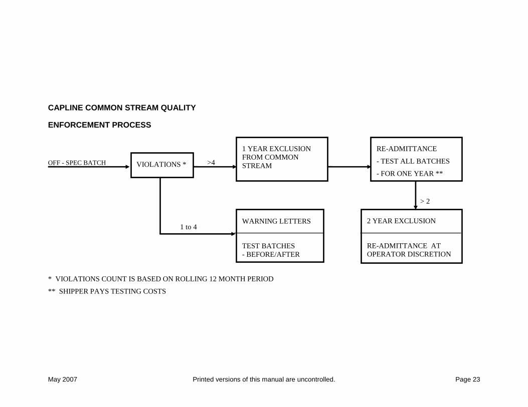
May 2007 Printed versions of this manual are uncontrolled. Page 23
CAPLINE COMMON STREAM QUALITY
ENFORCEMENT PROCESS
OFF - SPEC BATCH >4
> 2
1 to 4
* VIOLATIONS COUNT IS BASED ON ROLLING 12 MONTH PERIOD
** SHIPPER PAYS TESTING COSTS
1 YEAR EXCLUSION
FROM COMMON
STREAM VIOLATIONS *
2 YEAR EXCLUSION
RE-ADMITTANCE AT
OPERATOR DISCRETION
WARNING LETTERS
TEST BATCHES
- BEFORE/AFTER
RE-ADMITTANCE
- TEST ALL BATCHES
- FOR ONE YEAR **
May 2007 Printed versions of this manual are uncontrolled. Page 24
2.5 - Assay Requirements
2.5.1 - Introduction
At least two weeks prior to start up of a new receipt connection or at the nomination of a new
crude type, the carrier and / or shipper SHALL provide a complete assay from a reputable
laboratory. The Assay Report SHALL include:
1. Testing laboratory name and location
2. Date sample was taken - MUST be within five (5) years
3. Date sample was tested
4. Method used for each test
5. Test results for ALL properties required below
In addition to the complete assay, a Material Safety Data Sheet and some documentation
(technical bulletin or other) of the correct crude oil name (with company logo or letterhead) must
be submitted.
Results of the complete up-to-date assay from a reputable laboratory will be used to determine if
the crude oil is acceptable for shipment on the Capline System.
Upon approval of the newly nominated crude oil assay, the crude type will not be added to the
Capline approved Crude Oil Assay Listing until it has been shipped by the nominating carrier
and / or shipper and assayed by Capline. If this approved crude oil is not shipped within one
year of the approval date, the crude oil approval process SHALL be reinstituted before it can be
shipped in the system. If a crude has not been moved on the Capline System in three (3) years, it
will be removed from the approved assay list.
A blended crude will be treated as a new crude and requires a complete laboratory assay when
nominated, unless the component crude have been previously approved and shipped in the
Capline System. When the component crude of the nominated blend have been previously
accepted in the Capline System, the Carrier and/or Shipper may submit in writing a calculated
assay, instead of the complete laboratory assay mentioned above.
Oil acceptance will be at the discretion of the Operator's Capline Manager, Oil Movements, who
will make a comparison of the nominated new crude, blend, or any questionable oil, with
normally accepted crude oils. (A minimum of two weeks SHALL be allowed for approval or
rejection.)
May 2007 Printed versions of this manual are uncontrolled. Page 25
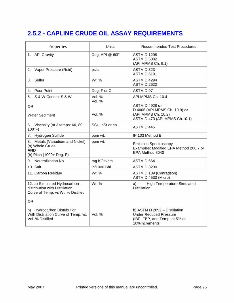
2.5.2 - CAPLINE CRUDE OIL ASSAY REQUIREMENTS
Properties Units Recommended Test Procedures
1. API Gravity Deg. API @ 60F ASTM D 1298 ASTM D 5002 (API MPMS Ch. 9.1)
2. Vapor Pressure (Reid) psia ASTM D 323 ASTM D 5191
3. Sulfur Wt. % ASTM D 4294 ASTM D 2622
4. Pour Point Deg. F or C ASTM D 97
5. S & W Content S & W
OR Water Sediment
Vol. % Vol. % Vol. %
API MPMS Ch. 10.4 ASTM D 4928 or D 4006 (API MPMS Ch. 10.9) or (API MPMS Ch. 10.2) ASTM D 473 (API MPMS Ch.10.1)
6. Viscosity (at 3 temps: 60, 80, 100°F)
SSU, cSt or cp ASTM D 445
7. Hydrogen Sulfide ppm wt. IP 103 Method B
8. Metals (Vanadium and Nickel) (a) Whole Crude AND (b) Pitch (1000+ Deg. F)
ppm wt. Emission Spectroscopy Examples: Modified EPA Method 200.7 or EPA Method 3040
9. Neutralization No. mg KOH/gm ASTM D 664
10. Salt lb/1000 Bbl ASTM D 3230
11. Carbon Residue Wt. % ASTM D 189 (Conradson) ASTM D 4530 (Micro)
12. a) Simulated Hydrocarbon distribution with Distillation Curve of Temp. vs Wt. % Distilled OR b) Hydrocarbon Distribution With Distillation Curve of Temp. vs. Vol. % Distilled
Wt. % Vol. %
a) High Temperature Simulated Distillation b) ASTM D 2892 – Distillation Under Reduced Pressure (IBP, FBP, and Temp. at 5% or 10%Increments
May 2007 Printed versions of this manual are uncontrolled. Page 26
2.6 - Quality Assurance Incident Report Form
2.6.1 - Quality Assurance Incident Report Form
May 2007 Printed versions of this manual are uncontrolled. Page 27
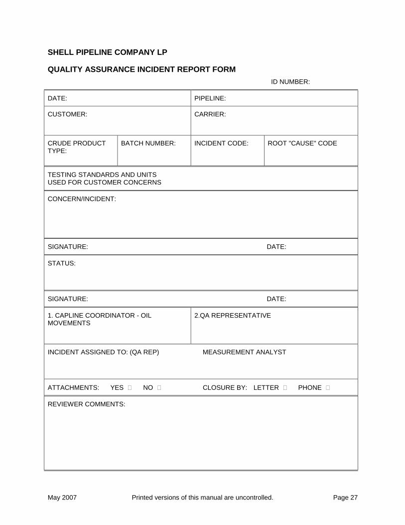
SHELL PIPELINE COMPANY LP
QUALITY ASSURANCE INCIDENT REPORT FORM
ID NUMBER:
DATE: PIPELINE:
CUSTOMER:
CARRIER:
CRUDE PRODUCT TYPE:
BATCH NUMBER: INCIDENT CODE: ROOT "CAUSE" CODE
TESTING STANDARDS AND UNITS USED FOR CUSTOMER CONCERNS
CONCERN/INCIDENT:
SIGNATURE: DATE:
STATUS:
SIGNATURE: DATE:
1. CAPLINE COORDINATOR - OIL MOVEMENTS
2.QA REPRESENTATIVE
INCIDENT ASSIGNED TO: (QA REP) MEASUREMENT ANALYST
ATTACHMENTS: YES NO CLOSURE BY: LETTER PHONE
REVIEWER COMMENTS:

May 2007 Printed versions of this manual are uncontrolled. Page 28
THIS PAGE INTENTIONALLY BLANK
May 2007 Printed versions of this manual are uncontrolled. Page 29
3.0 - Appendices
3.1 - Measurement Equipment
3.1.1 - Capline Equipment List
[Double click on the following icon to launch the Equipment List document.]
Capline Equipment List.xls
May 2007 Printed versions of this manual are uncontrolled. Page 30
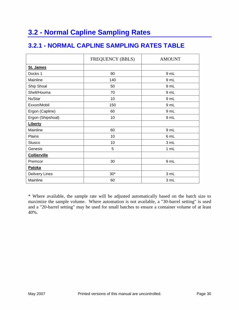
3.2 - Normal Capline Sampling Rates
3.2.1 - NORMAL CAPLINE SAMPLING RATES TABLE
FREQUENCY (BBLS) AMOUNT
St. James
Docks 1 90 9 mL
Mainline 140 9 mL
Ship Shoal 50 9 mL
Shell/Houma 70 9 mL
NuStar 10 9 mL
Exxon/Mobil 150 9 mL
Ergon (Capline) 60 9 mL
Ergon (Shipshoal) 10 9 mL
Liberty
Mainline 60 9 mL
Plains 10 6 mL
Stusco 10 3 mL
Genesis 5 1 mL
Collierville
Premcor 30 9 mL
Patoka
Delivery Lines 30* 3 mL
Mainline 60 3 mL
* Where available, the sample rate will be adjusted automatically based on the batch size to
maximize the sample volume. Where automation is not available, a "30-barrel setting" is used
and a "20-barrel setting" may be used for small batches to ensure a container volume of at least
40%.
May 2007 Printed versions of this manual are uncontrolled. Page 31
3.3 - Inspection and Calibration Frequencies
3.3.1 - Introduction
This section specifies the frequency of inspection and calibration to be conducted by the operator
of Capline. While maximum intervals are set out, it is recognized that these intervals depend
upon a number of factors such as maintenance requirements or weather conditions, the number
of spare units available, the attendance at the station, and the load on the system. The time
interval between inspections and servicing shall not be increased beyond the maximum outlined.
This section specifies only required inspections/calibrations and does not cover regular
observations of equipment condition and performance, which is an important part of a successful
maintenance program. In many cases such observations will uncover an equipment problem at
an early stage, thus limiting the down time and reducing repair costs. It is recommended that
these observations be made at regular intervals between required inspections as may be
appropriate for each location. Normally the observation can be made in connection with other
maintenance or operating activities without requiring special trips.
Inspection of equipment shall include:
1. Visual inspection to determine if there are signs of deterioration that might lead to failure.
2. Checking to verify that equipment is operating within design limits.
3. Servicing such as cleaning or lubrication.
4. The need to verify, calibrate and/or adjust devices to prescribed settings.
5. The need for repair of any device.
May 2007 Printed versions of this manual are uncontrolled. Page 32
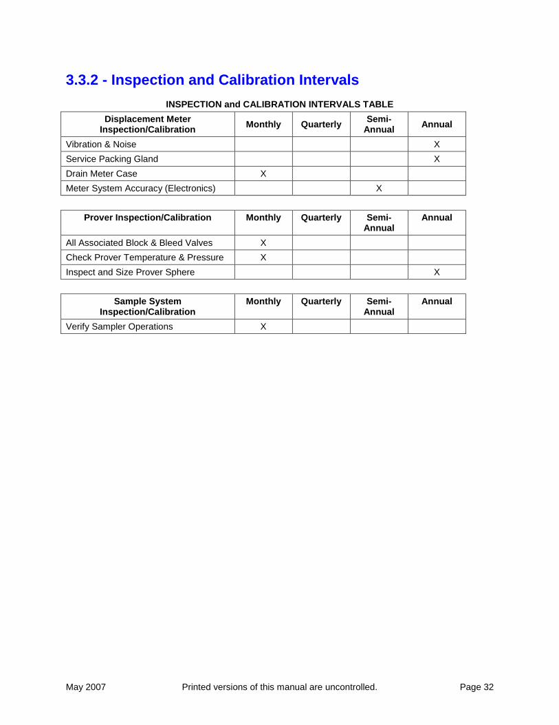
3.3.2 - Inspection and Calibration Intervals
INSPECTION and CALIBRATION INTERVALS TABLE
Displacement Meter Inspection/Calibration
Monthly Quarterly Semi-
Annual Annual
Vibration & Noise X
Service Packing Gland X
Drain Meter Case X
Meter System Accuracy (Electronics) X
Prover Inspection/Calibration Monthly Quarterly Semi-Annual
Annual
All Associated Block & Bleed Valves X
Check Prover Temperature & Pressure X
Inspect and Size Prover Sphere X
Sample System Inspection/Calibration
Monthly Quarterly Semi-Annual
Annual
Verify Sampler Operations X

May 2007 Printed versions of this manual are uncontrolled. Page 33

May 2007 Printed versions of this manual are uncontrolled. Page 34
3.3.2 - Portable Electronic Thermometers (Pet) Calibration And Verification Procedures
3.3.2.a - Initial and Annual Calibration
Before initial use, and at least once a year thereafter, each portable electronic thermometer shall
be calibrated in a laboratory or other qualified calibration facility.
The PET shall be calibrated by comparing it at three or more temperatures with a National
Institute of Standards and Technology (NIST) certified thermometer or an equivalent
thermometer of traceable accuracy. The PET manufacturer’s calibration procedures shall be
followed in conducting the calibration. Each calibration will ensure that accuracy is maintained
to ±0.5°F.
3.3.2.b - Field Verification and Inspection
This should be done before each use or once per day, whichever is less frequent. Each PET
should be spot checked by comparing against an NIST certified thermometer (or equivalent with
traceable accuracy) in liquid. If the readings differ by more than ±0.5°F, the PET should be
recalibrated before it is used for custody transfer measurement.
Additionally, the following physical inspections should be made before each use or daily. Any
damage found should be reported to your supervisor, and the PET should not be used for custody
transfer until repaired and reverified or recalibrated, whichever is appropriate.
1) The junction between the cable and the probe should be inspected for mechanical damage.
2) The cable insulation should be checked for cuts, breaks, or abrasion.
3.3.2.c - Monthly Verification
Each PET should be verified monthly at two or more temperatures near the ends of its range by
comparing it with an NIST certified thermometer or an equivalent with traceable accuracy. If
the thermometer readings differ by more than ±0.5°F, the PET should be recalibrated before it is
used for custody transfer.
May 2007 Printed versions of this manual are uncontrolled. Page 35
3.4 - Operational Guidelines
3.4.1 - Operational Guidelines List
Capline System measurement practices are documented elsewhere in this manual and require the
approval of Capline Owners. The following OPERATIONAL GUIDELINES have proven
beneficial to measurement practices:
1. HIGHLY VISCOUS CRUDES with viscosity at flowing temperatures in excess of 230 SSU
may cause meter factors to shift in excess of acceptable tolerances (see Section I.D.2.b and c:
Measurement Equipment And Procedures, Custody Volume Determination) necessitating the
use of secondary measurement. For this reason, all marine receipts of such crude will be
made across Dock No. 1.
2. SOLIDS in marine cargo’s, such as iron ore, sand, gravel, and grains will plug strainers and
damage metering equipment. If these materials cannot be avoided, operating precautions
should be taken such as extraordinary cleaning of strainers and close operating scrutiny.
Secondary measurement practices must be in place for these receipts.
3. BLENDING at receipt points or within the system is PROHIBITED, as there are no facilities
to accommodate this practice. All measurement is based on receipt/delivery of well-mixed,
uniform, and homogeneous crude oils for best accuracy. Batches must be uniform within
1 degree API gravity and 5 degree Fahrenheit limits.
4. LOW LINE VELOCITY at metering and sampling facilities should be avoided whenever
possible. During cargo stripping operations, dock meters operate below their specified low
flow limits resulting in inaccurate measurement. Because of this, lengthy stripping
operations should be avoided or investigated to determine if discharging should be
discontinued. Minimum flow rates are:
(a) DOCK 1 4,000 BPH
May 2007 Printed versions of this manual are uncontrolled. Page 36
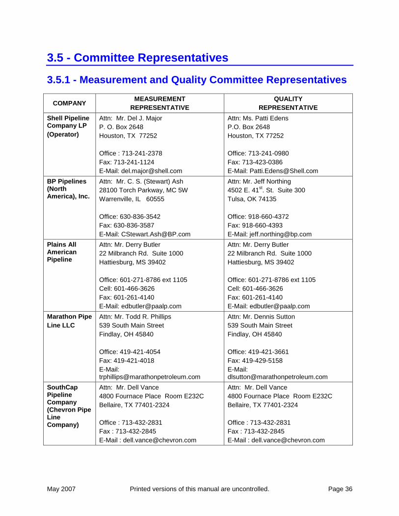
3.5 - Committee Representatives
3.5.1 - Measurement and Quality Committee Representatives
COMPANY MEASUREMENT
REPRESENTATIVE
QUALITY
REPRESENTATIVE
Shell Pipeline Company LP
(Operator)
Attn: Mr. Del J. Major
P. O. Box 2648
Houston, TX 77252
Office : 713-241-2378
Fax: 713-241-1124
E-Mail: [email protected]
Attn: Ms. Patti Edens
P.O. Box 2648
Houston, TX 77252
Office: 713-241-0980
Fax: 713-423-0386
E-Mail: [email protected]
BP Pipelines (North America), Inc.
Attn: Mr. C. S. (Stewart) Ash
28100 Torch Parkway, MC 5W
Warrenville, IL 60555
Office: 630-836-3542
Fax: 630-836-3587
E-Mail: [email protected]
Attn: Mr. Jeff Northing
4502 E. 41st. St. Suite 300
Tulsa, OK 74135
Office: 918-660-4372
Fax: 918-660-4393
E-Mail: [email protected]
Plains All American Pipeline
Attn: Mr. Derry Butler
22 Milbranch Rd. Suite 1000
Hattiesburg, MS 39402
Office: 601-271-8786 ext 1105
Cell: 601-466-3626
Fax: 601-261-4140
E-Mail: [email protected]
Attn: Mr. Derry Butler
22 Milbranch Rd. Suite 1000
Hattiesburg, MS 39402
Office: 601-271-8786 ext 1105
Cell: 601-466-3626
Fax: 601-261-4140
E-Mail: [email protected]
Marathon Pipe
Line LLC
Attn: Mr. Todd R. Phillips
539 South Main Street
Findlay, OH 45840
Office: 419-421-4054
Fax: 419-421-4018
E-Mail: [email protected]
Attn: Mr. Dennis Sutton
539 South Main Street
Findlay, OH 45840
Office: 419-421-3661
Fax: 419-429-5158
E-Mail: [email protected]
SouthCap Pipeline Company (Chevron Pipe Line Company)
Attn: Mr. Dell Vance
4800 Fournace Place Room E232C
Bellaire, TX 77401-2324
Office : 713-432-2831
Fax : 713-432-2845
E-Mail : [email protected]
Attn: Mr. Dell Vance
4800 Fournace Place Room E232C
Bellaire, TX 77401-2324
Office : 713-432-2831
Fax : 713-432-2845
E-Mail : [email protected]

May 2007 Printed versions of this manual are uncontrolled. Page 37
THIS PAGE INTENTIONALLY BLANK
May 2007 Printed versions of this manual are uncontrolled. Page 38
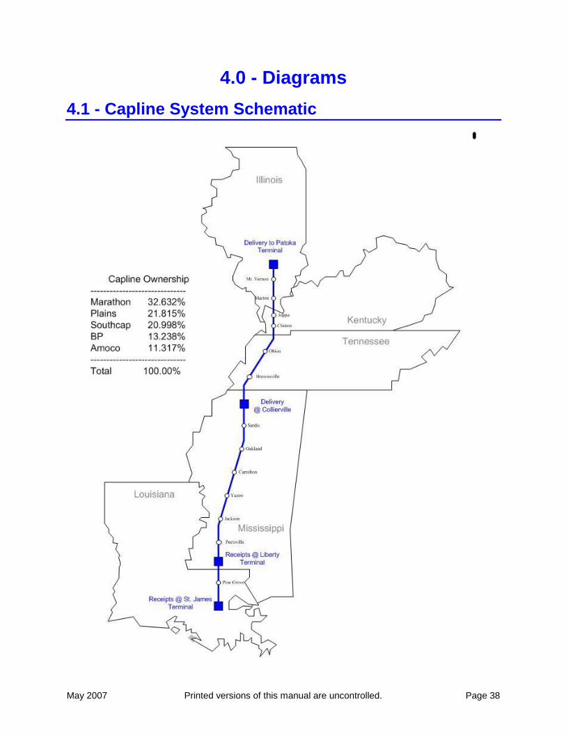
4.0 - Diagrams
4.1 - Capline System Schematic

May 2007 Printed versions of this manual are uncontrolled. Page 39
4.2 - St. James Receipts

May 2007 Printed versions of this manual are uncontrolled. Page 40
4.3 - St. James Receipts (cont.)
Plains - St James
36"
Bi-Directional
Prover
TO St. James Tankage
TO Capline Mainline
12" Helical
12" Helical
12" Helical
16" Helical
16" Helical
May 2007 Printed versions of this manual are uncontrolled. Page 41
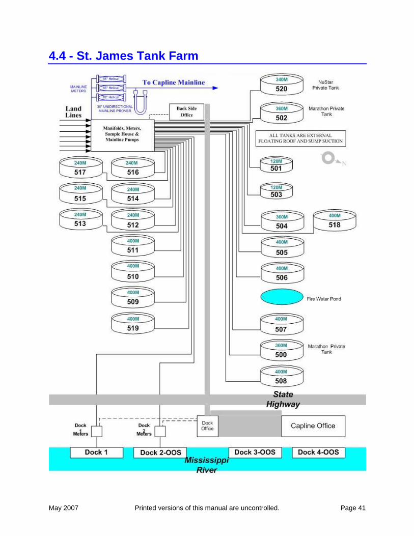
4.4 - St. James Tank Farm
May 2007 Printed versions of this manual are uncontrolled. Page 42
4.5 - Liberty Terminal
May 2007 Printed versions of this manual are uncontrolled. Page 43
4.6 - Collierville
May 2007 Printed versions of this manual are uncontrolled. Page 44
4.7 - Patoka Tank Farm

May 2007 Printed versions of this manual are uncontrolled. Page 45
4.8 - Patoka Deliveries


