48
Updated: July 2009

Updated: July 2009

Disclaimer
This publication was prepared for the Canadian Association of Petroleum Producers, the Gas Processing Association Canada, the Alberta Department of Energy, the Alberta Energy Resources and Conservation Board, Small Explorers and Producers Association of Canada and Natural Resources Canada by CETAC-West. While it is believed that the information contained herein is reliable under the conditions and subject to the limitations set out, CETAC-West and the funding organizations do not guarantee its accuracy. The use of this report or any information contained will be at the user’s sole risk, regardless of any fault or negligence of CETAC-West or the sponsors. Acknowledgements
This Fuel Gas Efficiency Best Management Practice Series was developed by CETAC WEST with contributions from:
• Accurata Inc. • Clearstone Engineering Ltd. • RCL Environmental • REM Technology Inc. • Sensor Environmental Services Ltd. • Sirius Products Inc. • Sulphur Experts Inc. • Amine Experts Inc. • Tartan Engineering
CETAC-WEST is a private sector, not-for-profit corporation with a mandate to encourage advancements in environmental and economic performance in Western Canada. The corporation has formed linkages between technology producers, industry experts, and industry associates to facilitate this process. Since 2000, CETAC-WEST has sponsored a highly successful eco-efficiency program aimed at reducing energy consumption in the Upstream Oil and Gas Industry. Head Office # 420, 715 - 5th Ave SW Calgary, Alberta Canada T2P2X6 Tel: (403) 777-9595 Fax: (403) 777-9599 [email protected]

Table of Contents 1. Applicability and Objectives 1 2. Basic Improvement Strategies 2 2.1 Technology and Equipment 2.2 Efficiency Assessment 2.3 Improving Efficiency 2.4 Personnel Training and Expertise 3. Inspection, Monitoring and Record Keeping 4 4. Rapid Feasibility Assessment 5 4.1 Burner Size 4.2 Heat Flux 4.3 Flame Diameter 4.4 Flame Intensity 4.5 Flame Length to Diameter Ratio 4.6 Venturi and Orifice Sizing 5. Operational Checks, Testing and Adjustments 10 5.1 Visual Checks 5.2 Operational Checks 5.3 Efficiency Tests 5.4 Trouble Shooting Guide 5.5 Maintenance Checks and Adjustments 6. Appendices 22
Appendix A Projected Fuel Gas Consumption Appendix B Design Considerations Appendix C Factors that Impact Heater Efficiency Appendix D Heater Upgrades/Replacement Options Appendix E Combustion Efficiency Calculation Appendix F Glossary of Terms Appendix G References

Tables
Table 1.1 Target Thermal Efficiencies for Various Types of Heaters Table 5.1 Recommended Operating Parameters for Efficient Operation Table 5.2 Common Symptoms and their Causes
Table A.1 Projected Fuel Gas Use for Fired Heaters Table A.2 Predicted Fuel Gas Consumption at Different Firing
Cycles Table B.1 Recommended Burner and Gas Orifice Sizes
Table B.2 Burner Flame Characteristics Figures
Figure 5.1 Flowchart of Operational Checks Figure B.1 Impact of L/D Fire Tube Aspect Ratio Figure C.1 Thermal Efficiency versus Excess Air Figure C.2 Effect of CO Emissions on Heater Efficiency
Figure C.3 Impact of Burner Firing Time on Efficiency

Background The issue of fuel gas consumption is increasingly important to the oil and gas industry. The development of this Best Management Practice (BMP) Module is sponsored by the Canadian Association of Petroleum Producers (CAPP), the Gas Processing Association Canada (GPAC), the Alberta Department of Energy, Small Explorers and Producers Association of Canada (SEPAC) Natural Resources Canada (NRC) and the Energy Resources and Conservation Board (ERCB) to promote the efficient use of fuel gas in gas fired devices used in the upstream oil and gas sector. It is part of a series of 17 modules addressing fuel gas efficiency in a range of devices.
This BMP Module:
• identifies the typical impediments to achieving high levels of operating efficiency with respect to fuel gas consumption,
• presents strategies for achieving cost effective improvements through inspection, maintenance, operating practices and the replacement of underperforming components, and
• identifies technical considerations and limitations. The aim is to provide practical guidance to operators for achieving fuel gas efficient operation while recognizing the specific requirements of individual fired heaters and their service requirements.

EFFICIENT USE OF FUEL GAS IN THE UPSTREAM OIL AND GAS INDUSTRY
MODULE 6 of 17: Fired Heaters
FIELD
5. Che
mical In
jectio
n Pum
ps
1. Gath
ering
Sys
tems
6. Fir
ed H
eater
s
4. Fla
ring
3. Pne
umati
c Ins
trumen
ts
2. Pum
pjack
s
7. Eng
ines
10. D
esicc
ant D
ehyd
rator
s
8. Com
pres
sion
9. Glyc
ol Deh
ydra
tors
11. F
uel G
as M
easu
remen
t
SOUR GAS PLANTS
17. A
cid G
as In
jectio
n
15. S
ulphu
r Rec
over
y
14. A
mine
13. R
efrige
ratio
n
12. F
racti
onati
on
5. Che
mical In
jectio
n Pum
ps
6. Fir
ed H
eater
s
4. Fla
ring
3. Pne
umati
c Ins
trumen
ts
7. Eng
ines
10. D
esicc
ant D
ehyd
rator
s
8. Com
pres
sion
9. Glyc
ol Deh
ydra
tors
11. F
uel G
as M
easu
remen
t
16. T
ail G
as In
ciner
ation
SWEET GAS PLANTS
13. R
efrige
ratio
n
12. F
racti
onati
on
5. Che
mical In
jectio
n Pum
ps
6. Fir
ed H
eater
s
4. Fla
ring
3. Pne
umati
c Ins
trumen
ts
7. Eng
ines
10. D
esicc
ant D
ehyd
rator
s
8. Com
pres
sion
9. Glyc
ol Deh
ydra
tors
11. F
uel G
as M
easu
remen
t16
. Tail
Gas
Incin
erati
on

Efficient Use of Fuel Gas in Fired Heaters Rev Date 27/05/2008 Module 6 of 17 Page 1 of 42
1. Applicability and Objectives This Best Management Practice provides guidance for operating staff to identify ways to improve the thermal efficiency of fired heaters at upstream oil and gas facilities. The determination of fuel gas efficiency is made by prescribed tests and calculations that yield the thermal efficiency of the heater based upon the fuel input and stack gas losses. This measure of performance has the advantages of being well understood, easy to calculate and within the capability of inexpensive combustion gas analyzers. The majority of fired heaters use sweet natural gas or sales gas for fuel but may also use propane. This module is applicable to both types of fuel, but differences in heating values must be used in calculating the thermal efficiency. Historically, fire-tube heaters were designed to provide reliable operation with limited operator intervention. Many heaters operate in remote locations putting a high emphasis on reliability. In support of this, heaters are generally fitted with a minimal control system relying on things like fixed orifices and wide performance margins. In addition, heaters are often sold with a higher capacity than is required for conservative operating practices. The majority of fired heaters in use are natural draft 2-pass fire tube design having a constant diameter which terminates into a vertical stack. Sizes range from a low of 100,000 BTU/h using single pass fire tube design to multiple pass fire tube heaters of over 6 MM BTU/h capacity. Some units may also have multiple fire tubes. Due to the significant differences in design and service of fired heaters, a single control objective is not technically sound; nor would it necessarily represent good performance over the range of service in which fired heaters are employed. For this reason, ranges of thermal efficiencies that represent efficient operation have been generated. The performance objectives are presented in Table 1.1.
Table 1.1 Target Thermal Efficiencies for Various Types of Heaters
Fired Device Thermal Efficiency (%) Water bath heater 75-82 Glycol heater 75-82 Amine reboiler 75-81 Hot oil heater 73-81 Glycol dehydrator 74-81 Salt bath heater 72-79 Regeneration gas heater 75-79 Steam boiler 78-83

Efficient Use of Fuel Gas in Fired Heaters Rev Date 27/05/2008 Module 6 of 17 Page 2 of 42
2. Basic Improvement Strategy The most significant elements of long-term operating efficiency are the application of best available technology, implementation of operating and maintenance systems and management commitment. Efficient operation of fired heaters requires:
• knowing what each fired heater was designed to do and what it is currently required to do,
• periodic checks and adjustments,
• routine testing and correction of abnormalities,
• assessment of opportunities to install upgrades and/or replacement of inefficient equipment, and
• maintenance of records.
2.1 Technology and Equipment The first step in moving toward higher levels of fuel gas efficiency is to understand what the heater was designed to do, and what modifications and changes may have been made since the heater was placed in service. This should provide an early indication of the suitability of the equipment for its current service, and, whether the equipment is likely to be able to meet its prescribed performance standards. Knowledge of the equipment will also help to identify what changes may be required to achieve higher levels of fuel gas efficiency. Following this, efforts should be made to bring the equipment in line with manufacture’s specifications for installation, use and maintenance. Section 4 of this module provides guidance for the assessment of fired heaters.
2.2 Efficiency Assessment Testing the thermal efficiency of a fired heater has, with the advent of economic combustion analyzers, become a quick and simple activity. Hand held analyzers are able to deliver thermal combustion efficiency in a matter of minutes. Such instruments also provide the information needed to quickly establish the most significant reasons for low efficiency, such as excess air or high stack gas temperature. Where there is no access to combustion gas analyzers, an approximation of thermal efficiency can be made by knowing the stack gas temperature and by observation of flame characteristics. It may be necessary to install stack temperature gauges and to ensure that adequate sight ports are available to observe the flame characteristics.

Efficient Use of Fuel Gas in Fired Heaters Rev Date 27/05/2008 Module 6 of 17 Page 3 of 42
Section 5 of this module describes methods to determine combustion efficiency supported by check sheets.
2.3 Improving Efficiency Decisions to carry out adjustments and/or replace components should be made on a case by case basis having consideration for health, safety, environmental and economic considerations. Where adjustments to existing systems are practical, these should be carried out at the time of testing. At such time, minor component replacements such as replacing a burner orifice can also be undertaken. When a total equipment outage is required before improvements can be undertaken, the repair/replacement may be delayed until the next planned shutdown provided this does not pose any safety concern. Section 5 of this module provides guidance for assessing performance deficiencies and possible corrective actions. Appendix C provides information on the factors that can have significant impact on heater efficiency.
2.4 Training/Expertise of Personnel Operation of fired heaters is not a complex task but personnel should know what to look for and what adjustments can safely be made. Adjustments and/or replacement of burners and the fuel gas train should only be performed by qualified trade personnel.

Efficient Use of Fuel Gas in Fired Heaters Rev Date 27/05/2008 Module 6 of 17 Page 4 of 42
3. Inspection, Monitoring and Record Keeping Operators should have a record program to support the company’s fired heater testing and improvement system. Proper record keeping should assist in ensuring that sub-optimal heaters are identified and that appropriate follow-up actions are implemented. This information will also assist in establishing the checking/testing frequency for each heater to achieve cost-effective fuel gas efficiency improvements. Although each company will define its record keeping system, consideration should be given to recording and retaining the following information:
• data sheets for each fired heater in service,
• expected fuel gas consumption by each heater,
• records of changes/upgrades that have been performed,
• efficiency testing results, and
• the economic analysis performed on low efficiency heaters, where they that have not been adjusted/modified on economic grounds.
Record keeping in support of a company’s fuel gas estimates, where measurement is not provided, may be audited by the ERCB to assess compliance with sections 17.1 (ii) and 17.2 (v) of ERCB Directive 017. In addition records need to be maintained to demonstrate compliance with sections 5.9.7 and 5.9.14 of ERCB Directive 056 related to NOx and SOx emissions. Appendix A provides the expected fuel gas consumption for fired heaters over the range of sizes most commonly encountered. Shaded areas in Tables A1 and A2 depict the need for fuel gas measurement per Directive 017.

Efficient Use of Fuel Gas in Fired Heaters Rev Date 27/05/2008 Module 6 of 17 Page 5 of 42
4. Rapid Feasibility Assessment of Fired Heating Devices
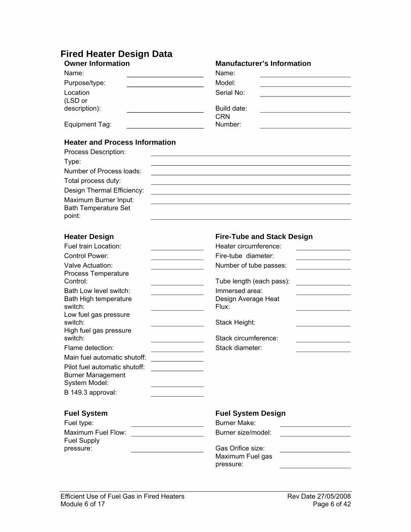
Fired heaters in different services and having different operating parameters will yield thermal efficiencies that may range from as high as 82% to as low as 70%. The upper limit is established by the need to maintain the flue gas temperature above the dew point while the lower level is determined by the process temperature. A low thermal efficiency is not automatically an indication of poor performance just as a high thermal efficiency is not automatically an indication of superior performance. In order to systematically evaluate the performance of fired heaters it is necessary to understand what each heater was intended and designed to do. In some cases original data sheets may be available and these should be retained. When original data sheets are not available, it is suggested that pertinent design data be collected and retained. To assist in the identification and recording of essential data, a Fired Heater Design Sheet is provided in this section of the module. The data required to complete this sheet is necessary in a proper evaluation of heater performance. It will also assist in identifying heaters that are inappropriately sized for current requirements and highlight features that may require modification or replacement. Using the information related to the design of a heater can provide an early indication of the likely efficiency and possible shortfalls. Appendix B contains information that should be referenced in evaluating a heater from design information.
Efficient Use of Fuel Gas in Fired Heaters Rev Date 27/05/2008 Module 6 of 17 Page 6 of 42
Fired Heater Design Data Owner Information Manufacturer’s Information Name: Name: Purpose/type: Model: Location Serial No: (LSD or description): Build date:
Equipment Tag: CRN Number:
Heater and Process Information Process Description: Type: Number of Process loads: Total process duty: Design Thermal Efficiency: Maximum Burner Input: Bath Temperature Set point:
Heater Design Fire-Tube and Stack Design Fuel train Location: Heater circumference: Control Power: Fire-tube diameter: Valve Actuation: Number of tube passes: Process Temperature Control: Tube length (each pass):
Bath Low level switch: Immersed area: Bath High temperature switch:
Design Average Heat Flux:
Low fuel gas pressure switch: Stack Height:
High fuel gas pressure switch: Stack circumference:
Flame detection: Stack diameter: Main fuel automatic shutoff: Pilot fuel automatic shutoff: Burner Management System Model:
B 149.3 approval: Fuel System Fuel System Design Fuel type: Burner Make: Maximum Fuel Flow: Burner size/model: Fuel Supply pressure: Gas Orifice size:
Maximum Fuel gas pressure:

Efficient Use of Fuel Gas in Fired Heaters Rev Date 27/05/2008 Module 6 of 17 Page 7 of 42
The design data or the data collected can provide a good indication as to whether the heater is likely to achieve the desired operational performance. In some instances it will be found that the heater and its components are mismatched. In order to better understand the capabilities of a particular heater, the following aspects of the heater should be examined.
4.1 Burner Size Heaters are intended to deliver a specified load or heat to the process. This is the heater duty or rating. In order to deliver this duty, designers have typically assumed a heater efficiency of 70%. Thus if the heater duty is 5 MMBtu/h, a burner with a rating of about 7.5 MMBtu/h is likely to be selected. If the burner rating is too high, the heater will be over fired when the burner is on and the firing cycle will be lower than is desirable. Both of these result in unintended heat losses and lower efficiencies. If the burner is too small the heater will be unable to meet the process duty.
4.2 Heat Flux Heat flux is a measure of the intensity of the energy flow. In the case of fired heaters this is expressed as the energy released by combusting fuel and must be transmitted through the available surface area of the fire tube. Historically the industry design factor has long been to achieve a heat flux of 10,000 Btu/h.ft2. Testing conducted as part of a 2005 PTAC project showed that this heat flux represents an over-fired situation and one that will result in an efficiency of less than 72%. The PTAC study showed that lower heat flux results in higher efficiencies and that a heat flux of 6,000 Btu/h.ft2 is almost certain to result in efficiencies higher than 72%1
4.3 Flame Diameter In order for a burner and fire-tube to effectively transfer the heat released by combustion to the working fluid, the burner and tube must be “matched”. The burner or specifically the flame pattern produced by the burner must fit the tube. A flame that is too large in diameter for the tube will result in flame impingement leading to tube wall oxidation and high CO levels due to premature quenching of the flame. A flame that is too small will be ineffective in radiant heat transfer resulting in reduced heat transfer and high stack temperatures. An ideal flame will have a diameter that is 4 to 6 inches less than the diameter of the tube.

Efficient Use of Fuel Gas in Fired Heaters Rev Date 27/05/2008 Module 6 of 17 Page 8 of 42
Properly designed and operated burners will produce a flame diameter that is about 3 times the burner diameter. This means a 2” burner should have a flame diameter of about 6” and this would fit a 10” fire-tube.
4.4 Flame Intensity Flame intensity is the measure of the heat released within the volume of the flame (Btu/h.ft3). A burner flame having a high intensity indicates rapid combustion and is indicative of the correct air to fuel ratio and good mixing of the air and fuel. A flame intensity of 600,000 Btu/h.ft3 or higher is desirable and attainable from aspirating burners.
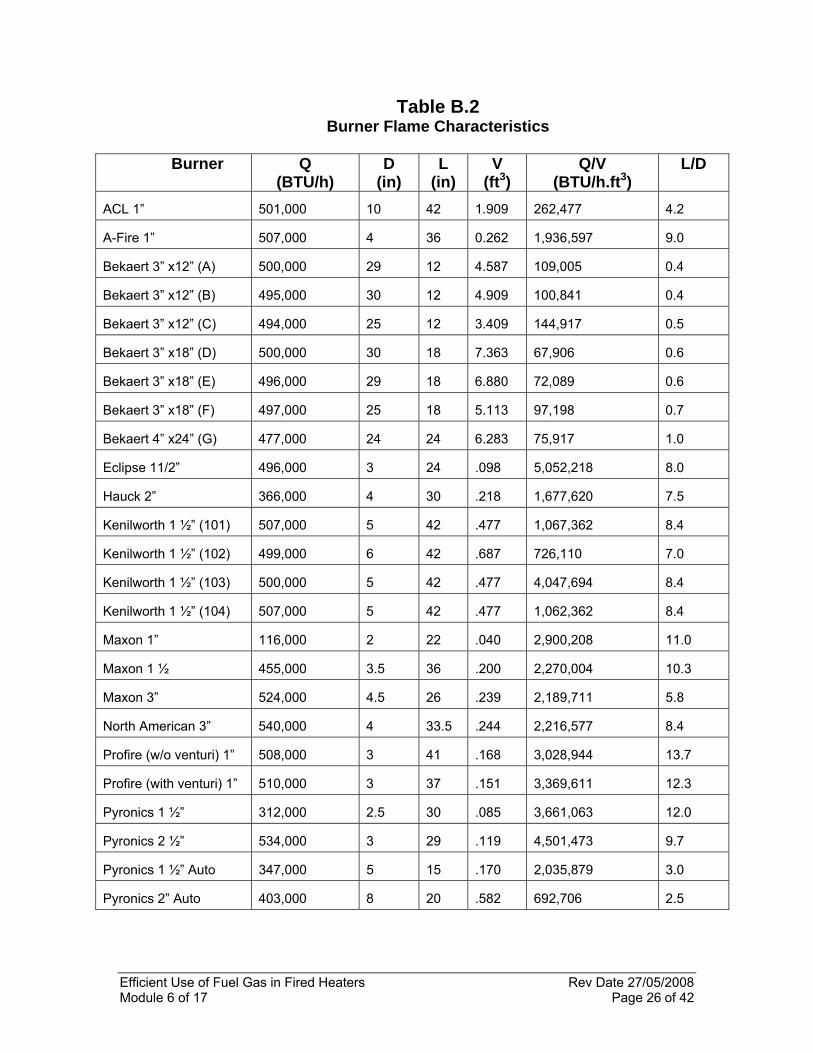
4.5 Flame Length to Diameter Ratio An overly long flame is a symptom of insufficient air or poor mixing of the air and fuel. Long flames are also more likely to impinge on the wall of the fire-tube. A length to diameter ratio of between 5 and 10 is considered ideal for fire-tube heaters. Burner characteristics described in section 4.3, 4.4 and 4.5, were examined in the 2005 PTAC project for a number of the more common burners used in fire-tube heaters. These characteristics are presented in Table B2, Appendix B.
4.6 Venturi and Orifice Sizing In aspirating burners, air is pulled into the burner by the pressure drop resulting from the flow of the fuel gas through a venturi nozzle. If the venturi diameter is too small, sufficient air will not be inducted, resulting in insufficient primary air to complete the combustion. In general, the venturi cross section should be such that the fuel gas energy is in the range of 100,000 to 120,000 Btu/h.in2. Orifice sizing is also critical to proper burner operation. A properly sized orifice should allow for stable operation at full capacity down to one third to one quarter capacity. The orifice is also an important component in terms of ensuring that the burner can inspire sufficient air for the fuel flow. The PTAC work also identified recommended firing rates and venturi sizes that will, in most instances, produce flames that are well suited to fire-tube applications. Recommended orifice sizes for various burner ratings are shown in Table B1, Appendix B.

Efficient Use of Fuel Gas in Fired Heaters Rev Date 27/05/2008 Module 6 of 17 Page 9 of 42
During the course of assessing a particular burner/heater, if it is found that the characteristics are outside of the suggested ranges, it does not mean the heater is ineffective. Rather it will help in establishing a priority list of heaters that should be candidates for an efficiency test. The data assembled will also be helpful in interpreting the results from the efficiency testing and identifying likely causes for poor performance.

Efficient Use of Fuel Gas in Fired Heaters Rev Date 27/05/2008 Module 6 of 17 Page 10 of 42
5. Operational Checks, Testing and Adjustments The impact of performance and service requirements on efficiency necessitates the identification of what constitutes good performance for each class of heater over the range of process conditions that is normally encountered. No heater can perform at 100% efficiency simply because the stack gases cannot be cooled to a temperature lower than the bath temperature and reasonably no lower than 50°C above the bath temperature at best. For this reason, a heater that operates at a high bath temperature (e.g. a salt bath heater) will have a lower thermal efficiency than a heater that operates at lower bath temperature (e.g. a glycol heater). As shown in Table 1, an achievable theoretical efficiency for fire-tube heaters is between 72% and 82% depending on bath temperature. Attaining these levels of performance may not be possible in all cases especially when a heater is grossly oversized in its current setting. Heaters that cannot meet the objective are candidates for upgrade or replacement. Because the determination of thermal efficiency requires more information than is generally available to field personnel, it is useful to direct attention to a few critical operating parameters and routine checks that will bring about a safe operation and promote fuel gas efficiency. The recommended ranges of such parameters are shown in Table 5.1.
Table 5.1 Recommended Operating Parameters for Efficient Operation
Parameter Target Stack temperature < 150°C above bath temperature Burner Firing Cycle > 70% Stack O2 < 3% Stack CO < 400 ppm
The stack temperature and burner firing cycle can be determined by the use of a hand held thermometer gun and a watch. It is recommended that stack gas analysis be determined as often as possible but at least on a semi-annual basis.

Efficient Use of Fuel Gas in Fired Heaters Rev Date 27/05/2008 Module 6 of 17 Page 11 of 42
In order to assist in improving operations, three distinct but related procedures have been developed. These are:
• visual checks,
• operational checks, and
• efficiency testing.
In addition, semi-annual maintenance checks have been developed. A description of each of these activities is set forth below. Check-sheets that record the results of these inspections and tests are included at the end of the description of each check/test.
5.1 Visual Checks The purpose of the visual checks is primarily to ensure that the heater is operating safely. These checks can be performed during a site “walk around”. They require no specialized tools or equipment and should be undertaken on a daily to weekly basis depending on the availability of operating personnel. The visual checks are limited to a total of six items and do not require any adjustments to be made. In the event that an abnormality is detected it is anticipated that this would be reported or that the more extensive operational checks would be initiated. The time required to carry out the visual checks is in the range of 5 to 15 minutes.

Efficient Use of Fuel Gas in Fired Heaters Rev Date 27/05/2008 Module 6 of 17 Page 12 of 42
Visual Checklist
Heater Location: Date: Heater Tag Number: Time: Heater In Service: (Y/N):
Item Activity Comments Gas Leak Check Check area around the
heater, the fuel gas train and enclosed areas for H2S, O2 and LEL
Heater Externals Check for missing insulation, corrosion, leaks and damage to instruments and fuel systems
Pilot When main burner is not firing, check pilot. The pilot should have a flame of between 4 and 8 inches in length
Main Flame When burner is firing, observe shape and color. Flame should not impinge on fire-tube. Flame should be sharp and bluish in color
Fuel Pressure Fuel pressure downstream of regulator should be >15 psig.
Flame arrestors Flame arrestors should be clean and not obstructed or blocked. Check for frosting.
General Observations and Conditions: Operator:

Efficient Use of Fuel Gas in Fired Heaters Rev Date 27/05/2008 Module 6 of 17 Page 13 of 42
5.2 Operational Checks Operational checks are the first level of performance assessment for fired heaters and will go a long way to ensure that the heater is operating in an efficient manner. The operational checks include a number of the items covered under the visual checks but extend this to the observation of operating parameters that provide a good indication of heater efficiency. These checks require the use of portable temperature sensors if temperature gauges are not installed. Two parameters, the stack outlet temperature and the burner firing cycle provide a good indication of overall efficiency and an early indication of deteriorating performance. The spread between the process fluid temperatures and the stack flue gas temperature provides an indication of heat exchange capacity and tube fouling. Burner firing cycle times should be timed over at least two complete cycles and should be conducted when process loads are steady and normal. Limited adjustments may be made during the conduct of the operational checks and these may require the assistance of technicians. Operational checks should take no longer than 30 minutes to perform and are recommended to be conducted on a monthly to quarterly basis. The data collected from the operational checks should be used to adjust the frequency of both the operational checks and the efficiency tests.

Efficient Use of Fuel Gas in Fired Heaters Rev Date 27/05/2008 Module 6 of 17 Page 14 of 42
Operating Data Check-Sheet
Heater Location: Date:
Heater Tag Number: Time:
Heater In Service:
(Y/N):
Field Measurements and Data
Parameter Expected value Actual value Burner Fuel Gas Pressure: 15 -20 psig Bath Temperature: Set point Stack temperature: < 150OC above Bath Process Inlet Temperature: Process Outlet Temperature:
Within 50OC of Bath
Burner ON Time: > 70% Burner OFF Time: < 30%
General Observations and Conditions:
Feature Expected ActualFlame Colour
Bluish flame (orange flame and orange sparklers indicate incomplete combustion)
Flame sound Uniform humming (Pulsating indicates too little or two much air or gas flow)
Flame anchoring
Flame should be “attached to the burner”
Flame pattern
Flame should be well within the tube.
Operator:
Efficient Use of Fuel Gas in Fired Heaters Rev Date 27/05/2008 Module 6 of 17 Page 15 of 42
5.3 Efficiency Tests Efficiency tests are a formal survey of heater performance. Such testing will establish the performance of the fired heater and identify where action needs to be taken to improve performance. The efficiency test requires instruments capable of analysing for oxygen, carbon monoxide, stack bottom temperature and ambient temperature. Basic combustion gas analyzers can provide an efficiency figure based on these parameters but a full understanding and interpretation of the data collected requires a good understanding of combustion and familiarity with the design and operation of burners and heaters. Operators, maintenance, and technical personnel may be required to undertake these tests and evaluate the results. Appendix D provides the steps involved in performing a combustion efficiency calculation if this is to be done manually. An efficiency test may require several hours to perform and assess the results, more if adjustments need to be made and retesting to determine the effect of such changes. In addition to a combustion gas analyzer, calibration equipment may be required to set and adjust controller setting and test gauges may be required to check temperature and pressure devices. Efficiency tests should be performed at a frequency of one to three years. The data collected from the operations checks should be used to identify the worst performers and efforts made to test such units as soon as practical. To assist in interpreting the data and taking corrective actions during an efficiency test, a series of questions presented in the form of a flow chart and a trouble shooting guide are provided in this section. These are considered accompanying documents to the Efficiency Test Check-Sheet and may be employed during the test or when test data is being assessed. In addition guides for maintenance personnel are provided to cover the tasks to be performed.

Efficient Use of Fuel Gas in Fired Heaters Rev Date 27/05/2008 Module 6 of 17 Page 16 of 42
Heater Efficiency Performance and Test Record
Heater Location: Date: Heater Tag Number: Time: Heater In Service: (Y/N):
Test Record
Parameter Value
Fuel Type:
Burner Fuel Gas Pressure: Bath Temperature:
Process Inlet Temperature: Process Outlet Temperature:
Burner ON Time: Burner OFF Time: Stack temperature:
Ambient Temperature: Stack Gas O2: (%)
Stack Gas CO: (ppm) Stack Gas NOx (ppm) Stack Gas SOx (ppm)
Calculated Efficiency (%)
Observations and Comments: Tester:
Efficient Use of Fuel Gas in Fired Heaters Rev Date 27/05/2008 Module 6 of 17 Page 17 of 42
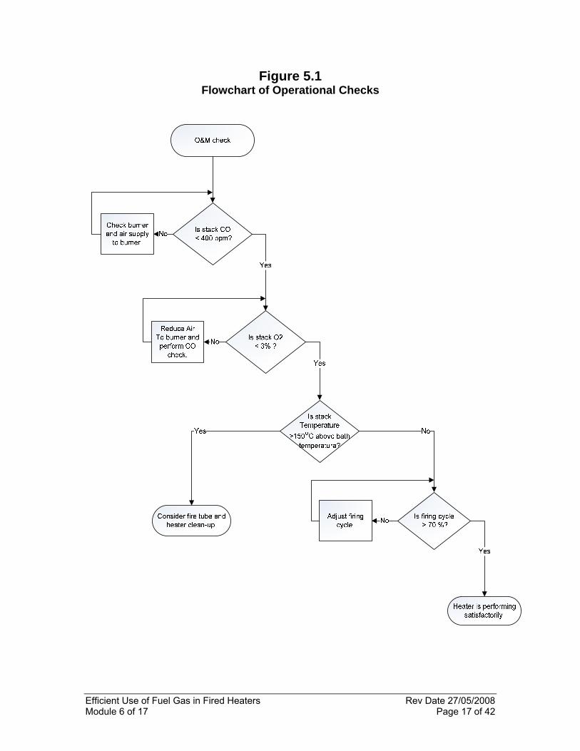
Figure 5.1 Flowchart of Operational Checks

Efficient Use of Fuel Gas in Fired Heaters Rev Date 27/05/2008 Module 6 of 17 Page 18 of 42
5.4 Trouble-shooting Guide To assist in identifying possible causes of improper operation of fired heaters, the following table has been prepared to assist in the problem solving and corrective action phase of heater performance. In many instances there is not a single problem but several problems occurring at the same time, any one of which can mask the others. In such cases, several paths may need to be followed to correct the problem. Changes should be made on a one at a time basis and a thorough recheck of the complete system should be made after each change. This is especially true when changes resulting in a decrease in air flow are made. Table 5.2 should be used in conjunction with the Efficiency Test Check-Sheet and the associated flow chart, Figure 5.1.

Efficient Use of Fuel Gas in Fired Heaters Rev Date 27/05/2008 Module 6 of 17 Page 19 of 42
Table 5.2 Common Symptoms and their Causes
Symptom Associated with Likely Cause Check High CO Low O2 Insufficient Air Restricted Air Intakes
Stack temperature/height/draft
Fuel Gas Pressure
Burner Characteristics
High CO High O2 Excess secondary air
Insufficient primary air
Secondary air registers
Fuel Gas Pressure
Burner characteristics
High CO Correct O2 Insufficient primary air
Poor air/Fuel mixing
Fuel Gas pressure
Burner characteristics
High O2 Correct CO Too much secondary air
Low aeration burner firing at low rate
Secondary air registers
Excessive Stack draft
High Stack Temperature
Correct Bath Temperature
Excessive firing rate
Long narrow flame
Dirty fire-tube
Undersized firing tube
Burner capacity
Heat Flux
Flame envelope within tube
Evidence of soot on tube
Heat transfer area
Low burner firing cycle
High stack temperature
Low process duty
Oversized burner
Process load vs design
Burner size vs heater duty
Insufficient Heater Capacity
Correct stack temperature and O2
Over design process load
Low flame intensity
Undersized Burner
Low Fuel Gas Pressure
External Losses
Process load vs design
Burner characteristics
Burner size vs heater capacity
Pressure downstream of regulator
Insulation
Efficient Use of Fuel Gas in Fired Heaters Rev Date 27/05/2008 Module 6 of 17 Page 20 of 42
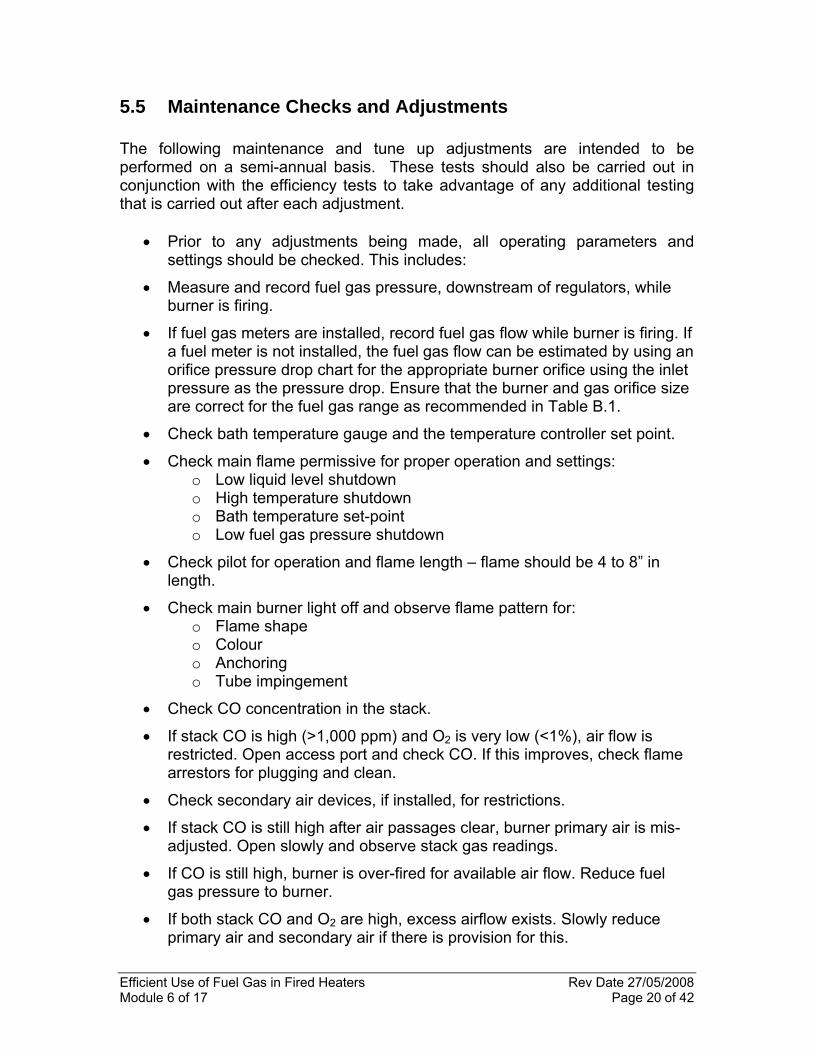
5.5 Maintenance Checks and Adjustments The following maintenance and tune up adjustments are intended to be performed on a semi-annual basis. These tests should also be carried out in conjunction with the efficiency tests to take advantage of any additional testing that is carried out after each adjustment.
• Prior to any adjustments being made, all operating parameters and settings should be checked. This includes:
• Measure and record fuel gas pressure, downstream of regulators, while burner is firing.
• If fuel gas meters are installed, record fuel gas flow while burner is firing. If a fuel meter is not installed, the fuel gas flow can be estimated by using an orifice pressure drop chart for the appropriate burner orifice using the inlet pressure as the pressure drop. Ensure that the burner and gas orifice size are correct for the fuel gas range as recommended in Table B.1.
• Check bath temperature gauge and the temperature controller set point.
• Check main flame permissive for proper operation and settings: o Low liquid level shutdown o High temperature shutdown o Bath temperature set-point o Low fuel gas pressure shutdown
• Check pilot for operation and flame length – flame should be 4 to 8” in length.
• Check main burner light off and observe flame pattern for: o Flame shape o Colour o Anchoring o Tube impingement
• Check CO concentration in the stack.
• If stack CO is high (>1,000 ppm) and O2 is very low (<1%), air flow is restricted. Open access port and check CO. If this improves, check flame arrestors for plugging and clean.
• Check secondary air devices, if installed, for restrictions.
• If stack CO is still high after air passages clear, burner primary air is mis-adjusted. Open slowly and observe stack gas readings.
• If CO is still high, burner is over-fired for available air flow. Reduce fuel gas pressure to burner.
• If both stack CO and O2 are high, excess airflow exists. Slowly reduce primary air and secondary air if there is provision for this.
Efficient Use of Fuel Gas in Fired Heaters Rev Date 27/05/2008 Module 6 of 17 Page 21 of 42
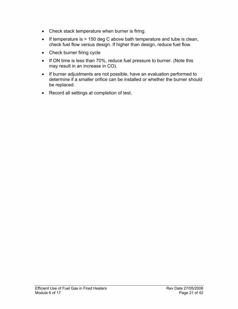
• Check stack temperature when burner is firing.
• If temperature is > 150 deg C above bath temperature and tube is clean, check fuel flow versus design. If higher than design, reduce fuel flow.
• Check burner firing cycle
• If ON time is less than 70%, reduce fuel pressure to burner. (Note this may result in an increase in CO).
• If burner adjustments are not possible, have an evaluation performed to determine if a smaller orifice can be installed or whether the burner should be replaced.
• Record all settings at completion of test.

Efficient Use of Fuel Gas in Fired Heaters Rev Date 27/05/2008 Module 6 of 17 Page 22 of 42
Appendix A Projected Fuel Gas Consumption
Table A.1
Projected Fuel Gas Use for Fired Heaters (Site metering required for areas in grey) Process Duty
(1) Fuel Gas Use
(2,3) Process Duty
(1) Fuel Gas Use (2,3) Btu/h scfd kW m3/d
100,000 3429 29 97 150,000 5143 44 146 200,000 6857 59 194 300,000 10286 88 291 400,000 13714 117 388 500,000 17143 147 485 600,000 20571 176 583 750,000 25714 220 728
1,000,000 34286 293 971 1,250,000 42857 366 1214 1,500,000 51429 440 1456 1,750,000 60000 513 1699 2,000,000 68571 586 1942 3,000,000 102857 879 2913 4,000,000 137143 1,172 3883 5,000,000 171429 1,465 4854
Notes:
(1) This is the nameplate duty or absorbed duty to the process. (2) The heating value of the gas is assumed to be methane at 1000 Btu/scf.
(3) The heater efficiency is assumed to be 70%.

Efficient Use of Fuel Gas in Fired Heaters Rev Date 27/05/2008 Module 6 of 17 Page 23 of 42
Table A.2 Predicted Fuel Gas Consumption at Different Firing Cycles
Projected Fuel Gas Use based on Firing Cycle
Process Duty Process Duty (sm3/d) Btu/h kW 10% 20% 30% 40% 50% 60% 70% 80% 90% 100%
100,000 29 10 19 29 39 49 58 68 78 87 97
150,000 44 15 29 44 58 73 87 102 117 131 146
200,000 59 19 39 58 78 97 117 136 155 175 194
300,000 88 29 58 87 117 146 175 204 233 262 291
400,000 117 39 78 117 155 194 233 272 311 350 388
500,000 147 49 97 146 194 243 291 340 388 437 485
600,000 176 58 117 175 233 291 350 408 466 524 583
750,000 220 73 146 218 291 364 437 510 583 655 728
1,000,000 293 97 194 291 388 485 583 680 777 874 971
1,250,000 366 121 243 364 485 607 728 850 971 1092 1214
1,500,000 440 146 291 437 583 728 874 1019 1165 1311 1456
1,750,000 513 170 340 510 680 850 1019 1189 1359 1529 1699
2,000,000 586 194 388 583 777 971 1165 1359 1553 1748 1942
3,000,000 879 291 583 874 1165 1456 1748 2039 2330 2621 2913
4,000,000 1,172 388 777 1165 1553 1942 2330 2718 3107 3495 3883
5,000,000 1,465 485 971 1456 1942 2913 3398 3883 4369 4854
Efficient Use of Fuel Gas in Fired Heaters Rev Date 27/05/2008 Module 6 of 17 Page 24 of 42
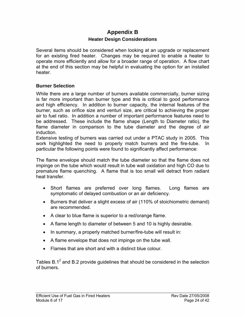
Appendix B Heater Design Considerations
Several items should be considered when looking at an upgrade or replacement for an existing fired heater. Changes may be required to enable a heater to operate more efficiently and allow for a broader range of operation. A flow chart at the end of this section may be helpful in evaluating the option for an installed heater. Burner Selection While there are a large number of burners available commercially, burner sizing is far more important than burner type and this is critical to good performance and high efficiency. In addition to burner capacity, the internal features of the burner, such as orifice size and venturi size, are critical to achieving the proper air to fuel ratio. In addition a number of important performance features need to be addressed. These include the flame shape (Length to Diameter ratio), the flame diameter in comparison to the tube diameter and the degree of air induction. Extensive testing of burners was carried out under a PTAC study in 2005. This work highlighted the need to properly match burners and the fire-tube. In particular the following points were found to significantly affect performance: The flame envelope should match the tube diameter so that the flame does not impinge on the tube which would result in tube wall oxidation and high CO due to premature flame quenching. A flame that is too small will detract from radiant heat transfer.
• Short flames are preferred over long flames. Long flames are symptomatic of delayed combustion or an air deficiency.
• Burners that deliver a slight excess of air (110% of stoichiometric demand) are recommended.
• A clear to blue flame is superior to a red/orange flame.
• A flame length to diameter of between 5 and 10 is highly desirable.
• In summary, a properly matched burner/fire-tube will result in:
• A flame envelope that does not impinge on the tube wall.
• Flames that are short and with a distinct blue colour.
Tables B.12 and B.2 provide guidelines that should be considered in the selection of burners.

Efficient Use of Fuel Gas in Fired Heaters Rev Date 27/05/2008 Module 6 of 17 Page 25 of 42
Table B.1
Recommended Burner and Gas Orifice Sizes
When the required burner capacity does not fit within the number in the above table, the next larger size should be selected with an appropriately sized orifice to maintain the fuel gas pressure drop. Thus for a 1,000,000 BTU heart, choose a 4” burner and an orifice of 5/32” (0.1562”) to maintain the burner to orifice section ration of about 430. It must be remembered that an undersized orifice in an oversized burner reduces the ability of the burner to induct air. Fire-tube Geometry The design of the fire-tube influences the efficiency of the heater in as much as a fire-tube with a higher L/D ratio generally results in higher heat transfer and hence higher efficiency than a fire-tube design with a lower L/D ratio. The reason for this is that the smaller diameter tube promotes radiant heat transfer and more turbulence in the fire-tube and thus decreases the cold spots which can occur in a larger diameter tube. Figure B 13 shows the effect of fire-tube L/D (length/diameter) ratio on efficiency.
Efficient Use of Fuel Gas in Fired Heaters Rev Date 27/05/2008 Module 6 of 17 Page 26 of 42
Table B.2 Burner Flame Characteristics
Burner Q
(BTU/h) D
(in) L
(in) V
(ft3) Q/V
(BTU/h.ft3) L/D
ACL 1” 501,000 10 42 1.909 262,477 4.2
A-Fire 1” 507,000 4 36 0.262 1,936,597 9.0
Bekaert 3” x12” (A) 500,000 29 12 4.587 109,005 0.4
Bekaert 3” x12” (B) 495,000 30 12 4.909 100,841 0.4
Bekaert 3” x12” (C) 494,000 25 12 3.409 144,917 0.5
Bekaert 3” x18” (D) 500,000 30 18 7.363 67,906 0.6
Bekaert 3” x18” (E) 496,000 29 18 6.880 72,089 0.6
Bekaert 3” x18” (F) 497,000 25 18 5.113 97,198 0.7
Bekaert 4” x24” (G) 477,000 24 24 6.283 75,917 1.0
Eclipse 11/2” 496,000 3 24 .098 5,052,218 8.0
Hauck 2” 366,000 4 30 .218 1,677,620 7.5
Kenilworth 1 ½” (101) 507,000 5 42 .477 1,067,362 8.4
Kenilworth 1 ½” (102) 499,000 6 42 .687 726,110 7.0
Kenilworth 1 ½” (103) 500,000 5 42 .477 4,047,694 8.4
Kenilworth 1 ½” (104) 507,000 5 42 .477 1,062,362 8.4
Maxon 1” 116,000 2 22 .040 2,900,208 11.0
Maxon 1 ½ 455,000 3.5 36 .200 2,270,004 10.3
Maxon 3” 524,000 4.5 26 .239 2,189,711 5.8
North American 3” 540,000 4 33.5 .244 2,216,577 8.4
Profire (w/o venturi) 1” 508,000 3 41 .168 3,028,944 13.7
Profire (with venturi) 1” 510,000 3 37 .151 3,369,611 12.3
Pyronics 1 ½” 312,000 2.5 30 .085 3,661,063 12.0
Pyronics 2 ½” 534,000 3 29 .119 4,501,473 9.7
Pyronics 1 ½” Auto 347,000 5 15 .170 2,035,879 3.0
Pyronics 2” Auto 403,000 8 20 .582 692,706 2.5

Efficient Use of Fuel Gas in Fired Heaters Rev Date 27/05/2008 Module 6 of 17 Page 27 of 42
Figure B.1

Efficient Use of Fuel Gas in Fired Heaters Rev Date 27/05/2008 Module 6 of 17 Page 28 of 42
Appendix C Fire-tube L/D ratio vs. Efficiency
Factors that Impact Heater Efficiency
Achieving high heater efficiency requires attention to many aspects of heater operation. The following material identifies the factors that influence efficiency and their relative magnitude. Fuel Type The type of fuel used impacts combustion efficiency primarily due to the impact of moisture losses. Fuels with high hydrogen to carbon ratio, produce more water vapour during combustion and have correspondingly higher wet gas losses. Excess Air (Fuel to Air Ratio) The fuel to air ratio influences heater efficiency. Insufficient air does not allow the fuel to be completely burned while too much air reduces the flame temperature and increases the stack losses thus the fire-tube efficiency decreases. In this module, the target value for excess air is 15% which equates to a stack oxygen concentration of 3% (based on methane as a fuel). Figure C1 shows the impact of excess air on heater efficiencies.
Figure C.1 Thermal Efficiency versus Excess Air
HEATER HHV EFFICIENCIES
0
10
20
30
40
50
60
70
80
90
100
200 400 600 800 1000 1200 1400
Temperature Difference Between Bottom of Stack and Combustion Air Inlet (°F)
Gro
ss T
herm
al E
ffici
enci
es (%
HHV
)
20%Excess Air80% Excess Air100% Excess Air

Efficient Use of Fuel Gas in Fired Heaters Rev Date 27/05/2008 Module 6 of 17 Page 29 of 42
Stack CO CO in the stack is the result of incomplete combustion and its presence signifies a loss of the available energy from the fuel. The impact of CO is shown in Figure C2 below.
Figure C.2 Effect of CO Emissions on Heater Efficiency4
Burner The burner is a critical component and must properly mix the fuel gas with air, bring about complete combustion and produce a stable flame that does not impinge the fire-tube. Flue Gas Temperature Flue gas temperature is primarily driven by the bath temperature since most of the heat is transferred to the bath. However, the flue gas temperature is also affected by other factors such as excess air in the fire-tube, incomplete combustion, inappropriate fire-tube design as well as other heat losses in the heater. The general rule for flue gas temperature is that “A 20 deg C (36 deg F) reduction in flue gas temperature will improve boiler efficiency by about one percent.”5 Thus it is recommended to keep the flue gas exit temperatures at no more than 150 deg C (270 deg F) above the bath temperature. The flue gas temperature should be measured at the base of the stack where the combustion products leave the fire-tube.
0 10 20 30 40 50 60 70 80 90
100
200 400 600 800 1000 1200 1400
Temperature Difference Between Bottom of Stack and Combustion Air Inlet (°F)
0 ppm CO 20,000 ppm CO50,000 ppm CO
Ther
mal
Effi
cien
cies
(%)

Efficient Use of Fuel Gas in Fired Heaters Rev Date 27/05/2008 Module 6 of 17 Page 30 of 42
Fire-Tube Fouling Almost any type of fuel will leave a deposit on the inside of the fire-tube. This is known as fouling and a small layer of soot or deposit will decrease the heat transfer significantly. For example, a 0.8 mm layer of soot can reduce the heat transfer by 9.5%6 Similarly, the outside of the fire-tube can also be fouled. This is a more common occurrence in direct-fired heaters and the outside fouling will limit the heat transfer through the tube. Firing Cycle Heater losses are influenced by the firing cycle. The most efficient operation is when the heater is fired continuously and it is desirable therefore to adjust the burner firing rate to achieve the longest possible firing cycles. Most burners can be operated over a range of one third of the burner capacity to full capacity thus allowing considerable room to optimize the firing cycle. The impact of firing cycles is shown in Figure C3.
Figure C3
Impact of Burner Firing Time on Efficiency From the above graph it can be seen that a 50% firing cycle results in a 10% parasitic load while a 25% firing cycle results in a 25% loss in efficiency.

Efficient Use of Fuel Gas in Fired Heaters Rev Date 27/05/2008 Module 6 of 17 Page 31 of 42
Ambient Air Temperature Heater efficiency is affected by the temperature of the combustion air drawn into the burner. This cannot be changed unless the heater is equipped with a heat recovery device that warms the inlet air. The impact of ambient temperature on heater efficiency is shown below.
Preheating combustion air can be beneficial and one way to do this is to direct the incoming air over the stack. This should be done with caution and only after a proper assessment of the impact of a lower stack temperature on draft at the burner.

Efficient Use of Fuel Gas in Fired Heaters Rev Date 27/05/2008 Module 6 of 17 Page 32 of 42
Appendix D

Efficient Use of Fuel Gas in Fired Heaters Rev Date 27/05/2008 Module 6 of 17 Page 33 of 42
Appendix E Detailed Calculation of Combustion Efficiency
In this module, the thermal efficiency of the heater is defined as the combustion efficiency calculated on the basis of stack gas losses. This requires measuring the stack gas temperature, the stack gas oxygen (expressed as %) and the stack gas CO (expressed as ppm). Most combustion gas analyzers perform this calculation directly and display it. Details for performing efficiency calculations manually are presented below. Combustion efficiency is expressed as a percent and determined by subtracting individual stack heat losses, as percents, of the fuel’s heating value from the total heating value of the fuel (100%). Dry gas losses and latent heat loss due to H2 in the fuel are typically the largest sources of stack losses. Others can be included, such as heat loss from moisture in the air and fuel losses from the formation of CO rather than CO2. The basic for calculating efficiency is described in the ASME Power Test Code 4.1 and is presented below.
% Net combustion efficiency = 100 – (fuel heat losses/lb fuel)/fuel heating value/lb fuel)
Fuel heat losses = Lg + Lh +Lm + Lco
Where: Lg = heat loss due to dry gas. Lh = heat loss due to moisture from burning hydrogen. Lm = heat loss due to moisture in fuel. L co = heat loss from incomplete combustion.
Fuel heating value = Higher heating Value (HHV).
Heat loss due to dry gas losses (Lg)
Lg = Wg • Cp • (Tflue – T supply)
Where: Wg = the weight of the flue gases per pound of as-fired fuel. Cp = the specific heat of the exhausr gas mix. Tflue = flue temperature.
Tsupply =combustion air temperature. Wg = (44CO2 + 32O2 +28N2 + 28CO) • (Cb +((12 • S)/32)
12 • (CO2 +CO)
CO2, O2, CO and N2 are gas concentration expressed as percent. N2 is determined by subtracting CO2, CO and O2 from 100% Cb is the carbon content of the fuel. S is the sulphur content of the fuel.

Efficient Use of Fuel Gas in Fired Heaters Rev Date 27/05/2008 Module 6 of 17 Page 34 of 42
Cp is the specific heat that varies with temperature. A good estimate of Cp regardless of the fuel is determined from the simple equation:
Cp = 0.24 + 0.000038 • (Tflue-200)
Heat loss due to H20 from the combustion of hydrogen
Where the fuel, such as natural gas, has a high hydrogen content, latent heat loss from the water formation can be significant. Lh = 8.936 • H • (hl – hrw)
Where: 8.936 = the weight of heater formed for each hydrogen atom. H = fractional hydrogen content of the fuel. hl = enthalpy of water at the exhaust temperature and pressure.
hrw = enthalphy of water as a saturated liquid at the fuel supply temperature.
Heat loss due to moisture in fuel
Moisture in the fuel is determined from lab analysis. Lm = fraction fuel moisture • (hl – hrw)
Where: hl = enthalpy of water at exit gas tempersture and pressure.
Hrw = enthalphy of water as a saturated liquid at the fuel supply temperature.
Heat loss due from the formation of carbon monoxide (Lco) Carbon in the fuel reacts with oxygen to form CO first, then CO2 generating a total of 14,500 BTU’s per pound of carbon. If the reaction stops at CO, because of insufficient oxygen or poor mixing of fuel and air, 10,160 BTU’s of energy are lost.
Lco = (%CO) • 10,160 • Cb
(% CO2 + % CO)
Where: Cb = fractional carbon content.
If some of the fuel gases cannot be measured, there are a number of calculations that can be performed to generate this data. The more common of these are presented below.

Efficient Use of Fuel Gas in Fired Heaters Rev Date 27/05/2008 Module 6 of 17 Page 35 of 42
Determining CO2 using the O2 concentration If the type of fuel is known and the stack O2 is measured, the CO2 in the flue exhaust can be calculated.
The CO2 concentration is determined by using the following equation:
% CO2 (by volume) = CO2 (max) • (20.9 - % O2 measured) 20.9
Where CO2 (max) is the maximum concentration produced for the fuel used.
Calculating CO2(max) from the carbon content Complete combustion of a simple hydrocarbon CxHy produces a fixed amount of carbon dioxide. If the theoretical air is used (i.e. excess air is zero) the concentration of CO2 in the exhaust is at the maximum concentration. To calculate the maximum CO2 concentration it is assumed that water condesnses out leaving only CO2 and N2 (from the air) as gases in the exhaust stream.
%CO2 (max) = (moles CO2) • 100 (moles CO2 + moles N2)
For the simple hydrocarbon above
Moles CO2 = x moles Moles N2 = (4x + y) x 3.76
4
Excess airr calcualtion Excess air is determined by measuring the concentration of un-reacted O2 in the fuel gas. A good approximation for excess air, expressed as a percent, can be calculated from the equation below. This calculation is often used to automatically calculate Excess Air in electronic combustion analyzers. O2 and CO concentrations are obtained from sampling the stack gas.
% Excess Air = (%O2 – (%CO/2)) • 100
(20.9 – (%O2 - %CO2/2))

Efficient Use of Fuel Gas in Fired Heaters Rev Date 27/05/2008 Module 6 of 17 Page 36 of 42
An expression of excess air referred to as Lambda (λ) may also be encountered particularly when assessing internal combsution engines. The relationship between % Excess Air and Lambda is shown below:
λ= (% Excess Air) + 1
100
Combustion air calculation It is possible to predict the amount of air needed to completely burn one pound of fuel using the equation below. This calculates the theoretical air requirement.
Pounds Air/Pound Fuel = 11.53 • C + 34.34 • (H2 – O2/8) + 4.29 • S
C, H2, O2 and S are the fractions, by weight, of each constituent of the fuel
Efficient Use of Fuel Gas in Fired Heaters Rev Date 27/05/2008 Module 6 of 17 Page 37 of 42
Appendix F Glossary of Terms
AIR-FUEL RATIO - The ratio of the weight, or volume, of air to fuel.
AMBIENT AIR - The air that surrounds the equipment. The standard ambient air for performance calculations is air at 80 °F, 60% relative humidity, and a barometric pressure of 29.921 in. Hg, giving a specific humidity of 0.013 lb of water vapour per lb of dry air.
AMBIENT TEMPERATURE - The temperature of the air surrounding the equipment.
ASME - The American Society of Mechanical Engineers.
ASPIRATING BURNER - A burner in which the fuel in a gaseous form is burned in suspension, the air for combustion being supplied by bringing into contact with the fuel, air drawn through one or more openings by the lower static pressure created by the velocity of the fuel stream.
ATMOSPHERIC AIR - Air under the prevailing atmospheric conditions.
ATMOSPHERIC PRESSURE - The barometric reading of pressure exerted by the atmosphere. At sea level 14.7 lb per sq in. or 29.92 in. of mercury.
AVAILABLE DRAFT - The draft which may be utilized to cause the flow of air for combustion or the flow of products of combustion.
BAROMETRIC PRESSURE - Atmospheric pressure as determined by a barometer usually expressed in inches of mercury.
BRITISH THERMAL UNIT (Btu) - The mean British Thermal Unit is 1/180 of the heat required to raise the temperature of 1 lb of water from 32 °F to 212 °F at a constant atmospheric pressure. A Btu is essentially 252 calories.
BURNER - A device for the introduction of fuel and air into a furnace at the desired velocities, turbulence and concentration.
BURNER WINDBOX - A plenum chamber around a burner that provides for proper distribution and discharge of secondary air.
BURNER WINDBOX PRESSURE - The air pressure maintained in the windbox or plenum chamber measured above atmospheric pressure.
C - Carbon element, the principal combustible constituent of all fuels.
CO - Carbon monoxide.

Efficient Use of Fuel Gas in Fired Heaters Rev Date 27/05/2008 Module 6 of 17 Page 38 of 42
CO2 - Carbon dioxide.
COMBUSTIBLE LOSS - The loss representing the unliberated thermal energy occasioned by failure to oxidize completely some of the combustible matter in the fuel.
COMBUSTION - The rapid chemical combination of oxygen with the combustible elements of a fuel resulting in the release of heat.
COMBUSTION AIR - Air used in the combustion process. Air contains oxygen which is required to combust fuel. COMBUSTION EFFICIENCY - The effectiveness of the burner to completely burn the fuel. A well designed burner will operate with as little as 10 to 20% excess air, while converting all combustibles in the fuel to useful energy. COMPLETE COMBUSTION - The complete oxidation of all the combustible constituents of a fuel. CONDUCTION - The transmission of heat through and by means of matter unaccompanied by any obvious motion of the matter. CONVECTION - The transmission of heat by the circulation of a liquid or gas. It may be natural, with the circulation caused by buoyancy affects due to temperature differences, or forced with circulation caused by a mechanical device such as a fan or pump. DESIGN LOAD - The load for which a heater is designed, considered the maximum load to be carried. DEW POINT - The temperature at which condensation starts. DRAFT - The difference between atmospheric pressure and some lower pressure existing in the furnace stack or gas passages of a steam generating unit. DRY GAS - Gas containing no water vapour. DRY-GAS LOSS - The loss representing the difference between the heat content of the dry exhaust gases and their heat content at the temperature of ambient air. EFFICIENCY - The ratio of output to input. See also Combustion and Thermal Efficiency. EXCESS AIR - Air supplied for combustion in excess of that theoretically required for complete oxidation.

Efficient Use of Fuel Gas in Fired Heaters Rev Date 27/05/2008 Module 6 of 17 Page 39 of 42
FIRETUBE - A type of heater design in which combustion gases flow inside the tubes and process fluid is outside the tubes. FLAME - A luminous body of burning gas or vapour. FLAME SAFEGUARD - A control that sequences the burner through several stages of operation to provide proper air purge, ignition, normal operation, and shutdown for safe operation. FUEL GAS - The gaseous product of combustion in the fuel to the stack. FUEL-AIR MIXTURE - Mixture of fuel and air. FUEL-AIR RATIO - The ratio of the weight, or volume, of fuel to air. GAS ANALYSIS - The determination of the constituents of a gaseous mixture. GAS BURNER - A burner that uses gas or fuel GAS PRESSURE REGULATOR - A spring loaded, dead weighted or pressure balanced device which will maintain the gas pressure to the burner supply line. GAUGE PRESSURE - The pressure above atmospheric pressure. HEAT BALANCE - An accounting of the distribution of the heat input, output and losses. HEAT RELEASE RATE - Rate that describes the heat available per square foot of heat-absorbing surface in the furnace or per cubic foot of volume. HEATING SURFACE - Those surfaces which are exposed to products of combustion on one side and water on the other. This surface is measured on the side receiving the heat. HEATING VALUE - The quantity of heat released by a fuel through complete combustion. It is commonly expressed in Btu per lb, per gallon, or cu-ft. INCOMPLETE COMBUSTION - The partial oxidation of the combustible constituents of a fuel. MMBtu - Millions of Btus (British Thermal Units). MOISTURE - Water in the liquid or vapour phase.

Efficient Use of Fuel Gas in Fired Heaters Rev Date 27/05/2008 Module 6 of 17 Page 40 of 42
MOISTURE LOSS - The boiler fuel gas loss representing the difference in the heat content of the moisture in the exit gases and that at the temperature of the ambient air. NOx - Abbreviation for all of the family of oxides of nitrogen. ORIFICE - A calibrated opening or nozzle used to deliver fuel gas into the burner. PILOT - A flame which is utilized to ignite the fuel at the main burner or burners. ppm - Abbreviation for parts per million. Used in chemical determinations as one part per million parts by weight. PRIMARY AIR - Air introduced with the fuel at the burner. PRODUCTS OF COMBUSTION - The gases, vapours, and solids resulting form the combustion of fuel. RATED CAPACITY - The manufacturers stated capacity rating for mechanical equipment; for instance, the maximum continuous capacity in pounds of steam per hour for which a boiler is designed. SECONDARY AIR - Air for combustion supplied to the furnace to supplement the primary air. SHELL - The cylindrical portion of a pressure vessel. SOOT - Unburned particles of carbon derived from hydrocarbons. SPECIFIC HEAT - The quantity of heat, expressed in Btu, required to raise the temperature of 1 lb of a substance 1 deg F. STACK - A vertical conduit, which due to the difference in density between internal and external gases, creates a draft at its base. STACK DRAFT - The magnitude of the draft measured at the inlet to the stack. THEORETICAL AIR - The quantity of air required for perfect combustion. THERMAL EFFICIENCY - The efficiency of a heater, based on the ratio of heat absorbed to total heat input. This does not include heat loss from the boiler shell. TOTAL AIR - The total quantity of air supplied to the fuel and products of combustion. Percent total air is the ratio of total air to theoretical air, expressed as percent.

Efficient Use of Fuel Gas in Fired Heaters Rev Date 27/05/2008 Module 6 of 17 Page 41 of 42
TURNDOWN RATIO - Ratio of maximum to minimum fuel or steam input or boiler output. UNBURNED COMBUSTIBLE - The combustible portion of the fuel which is not completely oxidized.

Efficient Use of Fuel Gas in Fired Heaters Rev Date 27/05/2008 Module 6 of 17 Page 42 of 42
Appendix G References
1 Jachniak, Jozef. Improved Fire-tube Immersion Heater Efficiency Project.
PTAC August, 2005. Page 12-1. 2 Jachniak, Jozef. Improved Fire-tube Immersion Heater Efficiency Project.
PTAC August, 2005. Figure 15-2, page 15-7. 3 Ibid. Figure 12.12, page 12-16. 4 Jachniak, Jozef. Improved Fire-tube Immersion Heater Efficiency Project.
PTAC August, 2005. Figure 4.14, page 4-35. 5 Ibid. 6 Dockrill, Paul and Friedrich, Frank.“ Boilers and Heaters: Improving Energy
Efficiency”. Online: http://oee.nrcan.gc.ca/publications/infosource/pub/cipec/boilersheaters_foreword.cfm?attr=24


