Page 1
Proceedings of The 2014 IAJC-ISAM International Conference ISBN 978-1-60643-379-9
Capstone Project: PLC Control System with Integrated PID Controller for
Control System Optimization
Abdullah Al Atwa
Michigan Technological University
[email protected]
Ian Bumgardner
Michigan Technological University
[email protected]
Mohammed Bushlaibi
Michigan Technological University
[email protected]
Steven Castello
Michigan Technological University
[email protected]
Joshua Erickson
Michigan Technological University
[email protected]
Aleksandr Sergeyev
Michigan Technological University
[email protected]
Mohsen Azizi
Michigan Technological University
[email protected]
Abstract
A PLC with a PID controller is a simple and effective way to increase the efficiency of a
control system. This paper discusses the development of a control system and the analysis of a
PID controller used for system voltage regulation. The system is also to be used as an
educational tool for PLC instruction. The system implements PLC and PID control to increase
the efficiency of LED lighting adjustments to voltage changes to keep the voltage level at a
desired setpoint. Our system contains four key components that make up the control system
which include a solar panel, a stepper motor, LED lights, and a PLC/HMI. The solar panel
voltage is an input to the PLC, which reads the input voltage and then calculates the desired
LED output. Because of the voltage changes, the illumination from the LEDs will try to
Page 2
Proceedings of The 2014 IAJC-ISAM International Conference ISBN 978-1-60643-379-9
compensate for the solar panel voltage change. The implementation of P, PI, and PID
controllers is used to optimize system performance.
Introduction
The capstone project course is an intrinsic part of undergraduate education. Capstone projects
are widely regarded as an excellent mechanism for assessing the outcomes of engineering and
engineering technology programs and can serve as a direct measure of the quality of
graduates. Capstone projects provide an opportunity for students to demonstrate their critical
thinking skills and communication skills, as well as time and project management skills. The
capstone course prepares students to better understand the professional roles in the
engineering and technology community [1]. In many universities, senior-level capstone
courses have been incorporated as an integral part of engineering and engineering technology
education in an effort to correlate the practical side of engineering design and the engineering
curriculum. Such courses provide an experiential learning activity in which the analytical
knowledge gained from previous courses is joined with the practice of engineering in a final,
hands-on project [2-4]. The development of capstone design courses and corresponding
requirements have been influenced by various sources, including the Accreditation Board for
Engineering and Technology (ABET), industrial advisory boards (IAB), faculty leading
capstone projects, numerous industrial companies, and engineering research.
Earlier research [4-15] showed the importance of industry involvement in the capstone
environment, which became more than just the financial support described above. However,
support in the form of equipment, materials, and technical consulting is common and in most
cases necessary [6-8]. Most industrial sponsors have a liaison engineer who assists the
students and who follows the progress of the project [7, 10]. Other forms of industrial support
include providing awards for meritorious designs and assisting in the evaluation of teams and
projects [4]. More recent studies provide further in depth analysis on the importance of the
various benefits of capstone projects for the students' preparation for real world jobs. These
include, but not limited to the importance of industry involvement [16-18], familiarizing
students with product development process and system engineering [16, 19-23], improvement
in the professional skills of students [16, 21], providing multidisciplinary training [16, 22-
25], cultivating creative problem solving skills [16, 26],
and preparing students for
globalization [16, 27, 28]. Recently, a new trend in conducting capstone projects became
noticeable. Some capstone projects are sponsored by faculty members instead of industrial
partners playing an important role of supporting some larger scale externally funded faculty
research projects [16]. For example, Texas A&M University undergraduate students involved
in these projects as a capstone team had to work with graduate students, faculty members,
and potential customers. Software, hardware, interface, system integration, and testing all
involved other researchers instead of just the capstone team [16]. These types of projects may
resemble projects conducted in industrial settings, where multiple divisions have to
collaborate on a single, large-scale project. The intent of this article is to share the developed
at Michigan Tech an effective approach of working on the sponsored SD projects. In this
article, the authors present a team of students engaged in the faculty-sponsored project with
the goal of the development and proof of concept demonstration of integration of a
Page 3
Proceedings of The 2014 IAJC-ISAM International Conference ISBN 978-1-60643-379-9
programmable logic controller (PLC) with the human machine interface (HMI) to create an
effective PID controller. Upon completion of the project, the system will be used as a stand-
alone training solution to teach PLC, HMI concepts as well as the theory of the PID
controllers in introductory and advanced PLC courses in the EET program at the university.
The authors describe the project requirements, the significance of the project, specific project
outcomes, and assessment tools used to effectively evaluate the students’ success.
The implementation of a proportional-integral-derivative (PID) controller in a control system
can increase the performance of the system. PID control is a control algorithm that is widely
accepted and very common among industrial control systems. The PID control algorithm is
shown in Figure 1 is a closed loop system in which an input is read and the desired output is
computed based on magnitude, duration and the rate of change of the error. Three types of
gains are used to respond to the types of errors: proportional, integral, and derivative. The
controller uses these gains to minimize the overall error of the system, which is the difference
of setpoint and the system output. Proportional gain is related to the magnitude of the error,
integral gain is related to the duration of the error, and the derivative gain is related to the rate
of change of the error. The combination of these three gain constants is used to obtain
optimal system performance. Therefore, the goal of the system is to try to keep the output
value at a desired value called the set point. When the output differs from the set point value,
then the system should return the output to the set point as quickly and efficiently as possible.
This project is only focused on the PID control objective to “track” a step function, and other
types of control objectives are out of the scope of this project and hence left as future works.
The optimized system should minimize the effect of system perturbations on the output value
and keep the output constant at the value of the set point [31, 32].
A programmable logic controller (PLC) is a popular component in which PID control is
implemented. A PLC uses inputs of a system to control various system outputs. The main
objectives of the system were to implement PID control and to function as a learning tool to
teach the different aspects of PLCs and related components. Because of the wide use of PLCs
in automated systems in industry, it is important for students to have a hands-on experience
with the equipment [40]. Systems developed for instructional use and testing of PID
controllers are important for training and system improvements. A PID controller was
designed to help illustrate controller effects and the proper settings for a seminar on process
controls [39]. To try to improve the PID control, an adaptive PID Controller was developed
using MATLAB software [30]. Educational software aimed towards PID control has been
used [29] to help students learn about PID controllers by simulating different processes and
allowing the user to change the PID parameters of the controller. It is not always convenient
for training to be done in the traditional laboratory environment and a portable PLC system
was developed for training which can be done closer to the job [41]. With systems and
instructional tools aimed towards the use of PLC and PID controllers, such as the system
presented in this paper, users are able to understand and gain experience directly related to
real-world applications.
Page 4
Proceedings of The 2014 IAJC-ISAM International Conference ISBN 978-1-60643-379-9
Figure 1. PID control algorithm [38] The system design includes the integration of a solar panel, a stepper motor and LED lights
that are all controlled by a PLC. An HMI is used in the system to allow the user to control
various functions. HMIs are popularly used along with PLCs for control systems, where an
HMI allows the user to control and monitor the system remotely. The overall function of the
system consists of the LED lights aimed at the solar panel to produce a measurable output
voltage. The system consists of three LED lights, two control LEDs that are controlled by the
PID controller and a perturbation LED light that is user controlled.
The system is perturbed by changes in solar panel position and the perturbation light intensity
and rate of change. As a result, the control lights adjust in order to keep the output of the
solar panel at the set point. The perturbations to the solar panel are accomplished by the
movement of the stepper motor that is coupled to the solar panel by two gears. The
perturbation light is controlled by ladder logic programs implemented in the PLC. The user is
able to control the stepper motor function and the perturbation light through the HMI
interface.
This paper covers the aforementioned system implementation, including topics of design,
system component information, programming and testing. Results of P, PI, and PID
controller implementation into the system will be analyzed for system optimization.
Capstone Course Description
In the past several years, EET program in the School of Technology at Michigan Tech was
very successful in establishing collaboration with the industry. This, in turn, triggered nearly
all the capstone projects conducted in the EET program to be industry sponsored. Only
during the last four years, EET program has successfully completed 12 capstone projects with
10 of them being industry-sponsored. The benefits of having senior design (SD) projects
industry sponsored are very significant for both the students and faculties. On the other hand,
the faculty sponsored projects gain popularity as well. Students working on faculty-sponsored
projects have an opportunity to participate in externally funded research or conduct faculty-
Page 5
Proceedings of The 2014 IAJC-ISAM International Conference ISBN 978-1-60643-379-9
defined projects resulting in equipment that can further be used to enhance in class teaching
approaches.
A capstone course in the EET program requires the application of knowledge gained in lower
and upper division courses. Students participating in a capstone project demonstrate the
ability to perform independent and creative work by successfully completing a major design
project. Projects are normally team oriented, where the team consists of two to four members,
with one member chosen as team leader. Team oriented capstone projects provide a better
simulation of industrial environment, to better train today’s engineers. Weekly progress
reports are required, and the work culminates with a final report and oral presentations,
including a poster of the project. Six credits of senior project are required for graduation,
normally satisfied in two three-credit semesters.
Upon successful completion of the capstone project course, students should fulfill the
following course objectives:
• Prepare background research on applied electrical engineering technology.
• Research and organize data for synthesis.
• Prepare written reports.
• Prepare and present oral reports.
• Work in teams.
• Coordinate and work to meet scheduled deadlines and facilities, manage resources, etc.
• Consider non-engineering considerations in your work (e.g., economic issues, marketing
issues, esthetics).
At the beginning of the first semester, teams are required to prepare a typed project proposal
in a formal memo format, including a proposed timeline. During the course of the project,
student teams meet with their faculty advisor weekly to discuss the progress report. The
weekly formal memo is required the day prior to each weekly meeting and addresses the
following three areas: current progress, problems encountered and their resolution, and plan
for the following week. To stay on the top of industry requirements sponsoring the project
and to receive valuable engineering feedback, students conduct by-weekly Web conference
calls with industry liaisons. The oral and written reports due near the end of each semester are
to concern themselves with the progress made in each semester. The one at the end of the
first semester will be a progress report, with a full final report due at the end of the second
semester. To further improve the quality of capstone projects conducted in the EET program
in the School of Technology (SoT) at the Michigan Tech and make students experience as
participating in undergraduate research, in the middle of the second semester the team led by
the faculty prepares the paper to be further submitted in one of the engineering journals or
conference proceedings. In the author's opinion, this experience should become an integral
part of any capstone project since it derives an additional benefits previously not included in
the capstone environment. First, this requirement makes the students to fill them proud to be
engaged in undergraduate research, which in-turn derives more responsibility and teamwork.
Second, it provides the students with the opportunity to learn different styles of technical
Page 6
Proceedings of The 2014 IAJC-ISAM International Conference ISBN 978-1-60643-379-9
writing following required formats associated with various journals and conference
proceedings. The last, but not the least, it significantly improves graduates portfolio that
while looking for the job can “bring to the table” more than their competitors/applicants.
System Components
The control system consists of four main components: a solar panel, a stepper motor, LED
lights and a PLC/HMI. Along with the main components there were various sub-components
and a constructed system enclosure. The solar panel for the system is a Value Line Series, a
VLS-10W solar panel. The PID controller will be used to try to keep the solar panel output
voltage at the setpoint of the system. The solar panel is constructed of an anodized aluminum
frame with tempered glass that houses the polycrystalline module cells. The solar panel has
an open circuit voltage rating of 21.4 V, a maximum power rating of 10W and a maximum
power voltage rating of 17.1 V [33]. In choosing a solar panel an important factor was the
weight it would bear on the stepper motor. The VLS-10W was an ideal option as it only
weighs 1.2 kg/2.6 lbs and has a small area with dimensions of 14.17 in x 10.63 in x 1.38 in.
The SureStep STP-MTR-17060 [34] is a single shaft bipolar stepper motor with 125oz/in of
torque, 2amps/phase with a NEMA 17 in2 frame. The required stepper motor holding torque
needed to rotate the solar panel was calculated based on the solar panels weight and
dimensions. The calculations for the stepper motor torque required for a solar panel weighing
2.7 lbs and dimensions of 14.17 in x 10.63 x 1.38 in are listed below:
Torque (T) = Acceleration (α) × Inertia (J)
The required torque was calculated assuming that the motor must move 60 degrees per
second and needs to reach that speed in 0.5 sec.
Acceleration= α =2*Π*RPS/Time
(Π = 3.14), (RPS = 60 degree / 360 degree= 0.16667), and (Time equals = 0.5 sec), then
α =2(3.14) (0.16667rps)/0.5sec
Acceleration = 2.093 rad/sec2
Inertia = J = 1/12 m* (a2+b
2); m = mass =2.7lb = 43.2oz; a = length= 14.73 in;
b = width =10.63 in; J = 1187.9 * 0.00259 (conversion factor)
Inertia = 3.07 oz-in-sec
T = α × J = (3.07*2.093); Therefore the torque is T = 6.43 oz/in (at 0.16667 rps)
The selected stepper motor has a torque rating of 125oz/in, which is much higher than what is
required for the solar panel but was purchased to avoid motor overloaded.
This stepper motor requires a stepper drive in order to control motor movement and function.
SureStep offers various drivers that can be used to drive the STP-MTR-17060 stepper motor.
The system driver needed to be highly efficient and have flexible controls to give the system
Page 7
Proceedings of The 2014 IAJC-ISAM International Conference ISBN 978-1-60643-379-9
good performance options. The SureStep STP-DRV-4850 [35] was selected to drive our
stepper motor; it is powered by 24-48 VDC and uses the SureStepPro software [36] for
configuration.
The driver is capable of many different control modes such as step and direction, serial
indexing, and velocity mode [36]. In our system, the velocity mode was implemented for
easier speed control and ladder logic programming. In velocity mode the motor speed is
dependent on the analog voltage value sent to the driver. The speed selection range is 0.1
rev/sec at 1 V to 0.5 rev/sec at 5 V. The STEP input of the driver is used for the Run/Stop of
the motor, while the DIR input determines CW or CCW rotation. The analog value for speed
is connected to the Analog Input of the driver. For smoother solar panel movement the
stepper motor steps per revolution were set to 20,000 steps/rev.
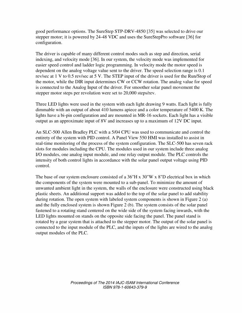
Three LED lights were used in the system with each light drawing 9 watts. Each light is fully
dimmable with an output of about 410 lumens apiece and a color temperature of 5400 K. The
lights have a bi-pin configuration and are mounted in MR-16 sockets. Each light has a visible
output as an approximate input of 8V and increases up to a maximum of 12V DC input.
An SLC-500 Allen Bradley PLC with a 5/04 CPU was used to communicate and control the
entirety of the system with PID control. A Panel View 550 HMI was installed to assist in
real-time monitoring of the process of the system configuration. The SLC-500 has seven rack
slots for modules including the CPU. The modules used in our system include three analog
I/O modules, one analog input module, and one relay output module. The PLC controls the
intensity of both control lights in accordance with the solar panel output voltage using PID
control.
The base of our system enclosure consisted of a 36"H x 30"W x 8"D electrical box in which
the components of the system were mounted to a sub-panel. To minimize the amount of
unwanted ambient light in the system, the walls of the enclosure were constructed using black
plastic sheets. An additional support was added to the top of the solar panel to add stability
during rotation. The open system with labeled system components is shown in Figure 2 (a)
and the fully enclosed system is shown Figure 2 (b). The system consists of the solar panel
fastened to a rotating stand centered on the wide side of the system facing inwards, with the
LED lights mounted on stands on the opposite side facing the panel. The panel stand is
rotated by a gear system that is attached to the stepper motor. The output of the solar panel is
connected to the input module of the PLC, and the inputs of the lights are wired to the analog
output modules of the PLC.
Page 8
Proceedings of The 2014 IAJC-ISAM International Conference ISBN 978-1-60643-379-9
(a) System components (b) Full enclosure
Figure 2. Complete system
System Development
The development of the system included various system components, wiring, power supplies,
etc. which will not be discussed in this paper in detail. A support stand for the solar panel
was designed in SolidWorks 3-D printed. To mount the solar panel stand in the enclosure a
housing mounted bearing was secured to the sub-panel and the stand base was secured within
the bearing. With the solar panel position finalized and secured, it was then wired to the
analog input module of the PLC. To couple the solar panel to the stepper motor, two gears
were designed and 3-D printed. One gear was connected to the shaft of the stand, and the
other was connected to the stepper motor shaft. For PLC control of the stepper motor, the
inputs of the stepper drive are wired to the relay output module of the PLC.
The stands used to mount the three LED lights in the system enclosure were designed in
SolidWorks and 3-D printed. The MR-16 bulb sockets were used for wiring and securing of
the LED bulbs within the stands. The desired angles were then calculated for both the control
and perturbation light stands, since the control lights would be at further distances from the
solar panel then the perturbation source. The stands were arranged to aim each light at the
center of the solar panel. RSLogix500 was used to program the SLC-500 PLC. The main
ladder logic program includes various different system functions that were implemented as
subroutines in the program. Figure 3 (a) shows the rungs of the main program that contain the
directional control of the stepper motor. The position tracking of the solar panel was done via
a timer and a counter and calculates the position based on the speed of the motor and how
long it is enabled. The ladder logic rungs shown in Figure 3 (b) make up the subroutine,
which is called when the oscillation mode is selected. The oscillation mode uses the
positioning system to change the direction of the stepper motor once the panel has traveled
just under 180º. The intensity range of the perturbation light can be selected range by the user
and the range selections include full, half, and quarter range. The implementation of the PID
Page 9
Proceedings of The 2014 IAJC-ISAM International Conference ISBN 978-1-60643-379-9
controller is accomplished by configuring both the PID setup screen shown in Figure 4 (a)
and the PID block shown in Figure 4 (b).
Figure 3. (a) Motor direction control (b) Oscillation mode
HMI system menus were developed using PanelBuilder32 [37] software to allow the user to
easily monitor and control the various functions of the system. The main menu of the system
is shown in Figure 5 (a) and is where the user is able to navigate to different control and
monitoring menus. With various HMI menus the user is able to adjust the perturbation LED
light intensity, start and stop oscillation, change oscillation speed, and select the intensity
range. The three selectable intensity ranges are full, half , and quarter range. Various user-
controlled stepper motor functions through the HMI include stepper motor starting and
stopping, selection of speed, direction, and mode. The three stepper motor movement modes
are oscillating, stop and manual/homing. Oscillation mode rotates the solar panel in a 180º
range of motion while alternating between clockwise (CW) and counterclockwise (CCW)
movement. Step mode rotates the solar panel from the center with a changing degree range.
Figure 4. (a) PID setup screen, (b) PID block
The panel’s initial rotation is 18º CCW from center, followed by the increase of 18º for the
next rotation range. The panel rotates up to 90º, then returns to center and switches the
Page 10
Proceedings of The 2014 IAJC-ISAM International Conference ISBN 978-1-60643-379-9
direction of rotation from CCW to CW and repeats the process in the CW direction. The
manual/homing mode is used for complete user controlled motor movement and for resetting
the system position. Figure 5 (b) shows the HMI screen which allows the user to view the
solar panel output voltage on a bar graph and number indicator in real-time alongside the
setpoint value.
Figure 5. (a) System main menu (b) Solar panel voltage monitoring
Results & Discussion
The testing of the PID controller in the system consisted of the implementation of a P, PI, and
PID controller. The initial testing was without any perturbations in the system and was done
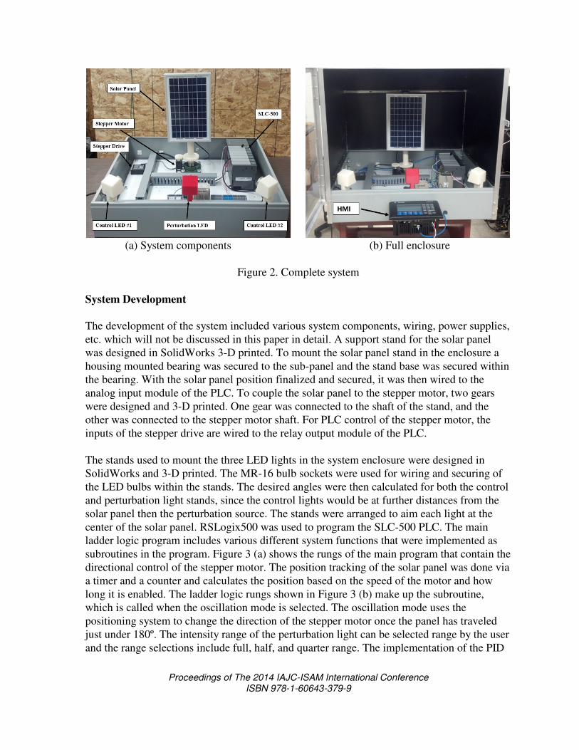
to see how fast and accurately the set point was reached when the system was started. Figure
6 shows the system response for implementing P controllers with proportional gains of 0.5,
0.95, and 5. The controller with a proportional gain of 5 has the fastest rise time and the
slowest settling time. This controller experiences the largest overshoot and is the only P
controller to experience oscillation. For a controller with the gain set to 0.95, the rise time
increases and the settling time decreases. With the decrease in the proportional constant the
overshoot has decreased and the oscillation has been removed. From the controller with a
proportional gain of 0.5 the overshoot is completely removed, but the rise time has increased.
Depending on the required rise time the proportional gain should be between 0.5-1 to
minimize overshoot and steady state error; otherwise, the performance will be weak in terms
overshoot, oscillations, and steady state error.
Page 11
Proceedings of The 2014 IAJC-ISAM International Conference ISBN 978-1-60643-379-9
Figure 6. P controller
Figure 7 shows the system response for implementing PI controllers with constant
proportional gains of 0.95 and integral gains of 1, 50, and 300. The results show that as
integral gain increases the rise time and settling time both slightly increase. The integral gain
should be set close to 250 to minimize rise time and additional more aggressive perturbation
scenarios will be used to validate various gain settings.
Figure 8 shows the system response for implementing PID controllers with constant
proportional gains of 0.95 and constant integral gains of 300 with derivative gains of 10, 75,
and 300. For a low derivative gain of 10 the system response was quite unstable and never
settled at the set point. For both derivative gains of 75 and 300 the system response was very
similar, with slightly better overshoot for the gain of 75. In comparison to the PI controller,
the addition of the derivative gain did not show a significant change in response. This was
expected because testing had minimal future perturbations for the derivative gain to respond
to. In Figure 8, the initial conditions are slightly different for the three test cases, and the
difference is less than 0.25(V), which is an acceptable range to make a fair comparison
among the three test cases. Additional testing will be done to further test the function of the
PID controller and to determine the desired gain parameters for different test scenarios.
Future test cases include changing the oscillation speed and intensity of the perturbation light,
rotating the solar panel at different speeds and movement patterns, and combining both test
cases to maximize the system perturbations for testing.
Page 12
Proceedings of The 2014 IAJC-ISAM International Conference ISBN 978-1-60643-379-9
Figure 7. PI controller
Figure 8. PID controller
Conclusion
The PID controller was implemented into the completed system and testing confirmed the
desired PID controller function. Based on initial results, an implemented PI controller with a
proportional gain of 0.6 and integral gain of 250 would be ideal for the system experiencing
minimal perturbations. For the system experiencing various perturbations, PID control should
help with system stability.
With topics addressed in the system such as the basic input/outputs, system troubleshooting,
complex PLC programming methods, HMI programming/implementation, and PID
controllers, this system can be used as an educational tool for students learning basic and
advanced PLC techniques. Through this capstone project, group members gained valuable
experience with components such as PLCs, HMIs, solar panels, and stepper motors, and it
has been a valuable learning experience completing a complex system from design to
completion.
Page 13
Proceedings of The 2014 IAJC-ISAM International Conference ISBN 978-1-60643-379-9
Academic programs in the School of Technology at Michigan Tech are designed to prepare
technical and/or management-oriented professionals for employment in industry, education,
government, and business. The EET program is constantly revamping the curriculum to meet
the expectations of industry by supplying qualified technicians and technologists who have
extensive hands-on experience. As part of the continuous effort leading to priority
consideration of graduates from the School of Technology an EET program at Michigan Tech
engaged a group of EET students in solving engineering problems as part of capstone
integrating experience and to fulfill the degree program requirements. Working with the
advisors, the team was challenged to integrate a programmable logic controller with the
human machine interface to create an effective PID controller.
With the conclusion of this project, the team was able to meet all of the requirements given
by the faculty advisor and fulfill the degree program requirements at Michigan Tech .
Successful assembly and testing of the unit was accomplished. An extensive tutorial includes
step-by-step instructions with images and figures on how to use HMI and PLC to run the pre-
programmed operational cycle of the PID controller. The tutorial also includes detailed
instructions on reconfiguring individual control functions to modify the operating cycle of the
system. The situational scenario is included in the tutorial and provides all necessary steps for
configuring HMI and programming PLC to achieve all the tasks. The developed tutorial
along with the build PID controlled system will serve the purpose of providing the hands-on
PLC, HMI, and PID theory training to the students enrolled in introductory and advanced
PLC courses.
Future Work
This senior design project research is being extended to further study the behavior of the
optical system in-depth and to improve the performance of the PID controller. So far, it is
identified that the optical system is highly nonlinear at some operating points and the
nonlinearity is due to a dead-band characteristic of the optical system. To this end, the
performance of the optical system (in a closed-loop configuration with the PID controller) is
very different from the performance of a linear system, and hence at some operating points,
the observations from the optical system contradict our expectations from a linear system.
This research is being continued and the nonlinearity in the optical system is being studied in
details. Therefore, this senior design research is ongoing , with the following directing future
work:
• The optical system will be investigated to analyze the dynamic model of the system.
• Once the dynamic model is analyzed, different PID controller design techniques will be
investigated, such as Ziegler-Nichols (ZN) and model-based techniques.
Page 14
Proceedings of The 2014 IAJC-ISAM International Conference ISBN 978-1-60643-379-9
References
[1] Bai, T., Zhu, J., & Varma, V. (2007). Characteristics of Capstone Design Projects at
Universities in US and China: An Analysis. Proceedings of the 2007 ASEE Annual
Conference. Paper #2007-1755.
[2] Dutson, A., Todd, R., Magleby, S. P., & Sorensen, C. D. (1997, January). A Review of
Literature on Teaching Engineering Design through Project-Oriented Capstone Courses.
Journal of Engineering Education. 86(1), 17-28.
[3] Pomberger, G. (1993). Software Engineering Education—Adjusting Our Sails.
Education and Computing, 8(4), 287-294.
[4] Thorpe, J. F. (1984). Design of Mechanical Systems: A Capstone Course in Mechanical
Engineering Design. Proceedings of the 1984 ASEE Annual Conference, 803-807.
[5] Todd, R. H., Magleby, S. P., Sorensen, C. D., Swan, B. R., & Anthony, D. K. (1995). A
Survey of Capstone Engineering Courses in North America. Journal of Engineering
Education, 84(2), 165-174.
[6] Banios, E. W. (1992). Teaching Engineering Practices. Proceedings of the 1992
Frontiers in Education Conference, 161-168.
[7] Todd, R. H., Sorensen, C. D., & Magleby, S. P. (1993). Designing a Senior Capstone
Course to Satisfy Industrial Customers. Journal of Engineering Education, 82(2), 92-
100.
[8] Rochefort, S. (1985). An Innovative ChE Process Laboratory. Chemical Engineering
Education, 19(3), 150-155, 161.
[9] Frechleton, J. E., & Walter, W W. (1994) Constructing Prototypes in a College-Wide
Capstone Design Course. Proceedings, Advances in Capstone Education Conference,
Brigham Young University,177-180.
[10] Durfee, W. K. (1994). Engineering Education Gets Real. Technology Review,97(2), 42-
52.
[11] Born, R. C. (1992). A Capstone Design Experience for Electrical Engineers. IEEE
Transactions in Education, 35, 240-242.
[12] Magleby, S. P., Sorensen, C. D., & Todd, R. H. (1992). Integrated Product and Process
Design: A Capstone Course in Mechanical and Manufacturing Engineering.
Proceedings of the 1992 Frontiers in Education Conference, 469-474.
[13] Sloan, D. E. (1982). An Experiential Design Course in Groups. Chemical Engineering
Education, 16(1), 38-41.
[14] Hamelink, J. H. (1994). Industrial Oriented Senior Design Projects: A Key for
Industrial Experience. Proceedings, Advances in Capstone Education Conference,
Brigham Young University, 87-89.
[15] Walter, W. W. (1991). Using a Large-Displacement General Purpose Dynamics Code in
a Capstone Design Course. Twenty-Third International SAMPE Conference, 288-296.
[16] Zhan, W., Goulart, E., Morgan, J., & Bird, M. (2012). Integration of Capstone
Experience and Externally Funded Faculty Research. Proceedings of the 2012 ASEE
Annual Conference. Paper #2012-3139
Page 15
Proceedings of The 2014 IAJC-ISAM International Conference ISBN 978-1-60643-379-9
[17] Brackin, M. P. & Gibson, J. D. (2005). Capstone Design Projects with Industry:
Emphasizing Teaming and Management Tools. Proceedings of the 2005 ASEE Annual
Conference.
[18] Karimi, A., Eftekhar, J., Manteufel, R., & Singh, Y. (2003). Industrially Supported
Projects in a Capstone Design Sequence. Proceedings of the 2003 ASEE Annual
Conference.
[19] Corns, S., Dagli, C. H., & Guardiola, I. G. (2011). SE Capstone: Integrating Systems
Engineering Fundamentals to Engineering Capstone Projects: Experiential and Active.
Proceedings of the 2011 ASEE Annual Conference.
[20] Crain, G. E. &Tull, M. P. (2004). A Capstone Course Targeting Industry Transition.
Proceedings of the 2004 ASEE Annual Conference.
[21] Gerbus, D., Cordon, D., Walker, M., Drew, R., Odom, E., Beyerlein, S., & Rink, K.
(2002). Improving the Professional Skills of Engineering Graduate Students through a
Capstone Project Mentoring in IEWorks. Proceedings of the 2002 ASEE Annual
Conference.
[22] King, L., El-Sayed, M., Sanders, M. S., & El-Sayed, J. (2005). Job Readiness through
Multidisciplinary Integrated Systems Capstone Courses. Proceedings of the 2005 ASEE
Annual Conference.
[23] Sheppard, K. G., Nastasi, J., Hole, E., & Russell, P. L. (2011). SE Capstone:
Implementing a Systems Engineering Framework for Multidisciplinary Capstone
Design. Proceedings of the 2011 ASEE Annual Conference.
[24] Redekopp, M., Raghavendra, C., Weber, A., Ragusa, G., & Wilbur, T. (2009). A Fully
Interdisciplinary Approach to Capstone Design Courses. Proceedings of the 2009 ASEE
Annual Conference.
[25] Seaward, G. H. (2001). Converting Single Disciplinary Capstone Projects to
Interdisciplinary Experiences. Proceedings of the 2001 ASEE Annual Conference.
[26] Lumsdaine, E. (2007). Creative Problem Solving in Capstone Design. Proceedings of
the 2007 ASEE Annual Conference.
[27] Lin, Y. & Harby, D. (2004). Teaching Capstone Design in Globalization Environment.
Proceedings of the 2004 ASEE Annual Conference.
[28] Lin, Y., Harby, D., Jang, D., & Ye, Z. Problems and Solutions in Internationalizing
Capstone Design. Proceedings of the 2005 ASEE Annual Conference.
[29] Cooper, D. J. (1996). PiclesA Simulator for “Virtual World” Education and Training in
Process Dynamics and Control. Proceedings of the 1996 ASEE Annual Conference
Proceedings.
[30] Rahrooh, A., Motlagh, B., & Buchanan, W. (2005). Adaptive PID Controller Using PC
MATLAB. Proceedings of the 2005 ASEE Annual Conference.
[31] National Instruments. (2011, March 29). PID Theory Explained. Retrieved from
http://www.ni.com/white-paper/3782/en/?vm=r&s=1
[32] Araki, M. (1984). PID Control. Control Systems, Robotics, and Automation, 2.
[33] Ameresco Solar. (2013). Value Line Series (VLS) - 10W Panel. Retrieved from
http://www.amerescosolar.com/sites/default/files/VLS-10W_1.pdf
[34] Automation Direct. (2014). STP-MTR-17060. Retrieved from
http://www.automationdirect.com/adc/Shopping/Catalog/Motion_Control/StepperSyste
ms/Stepper_Motors_-z-_Cables/STP-MTR-17060
Page 16
Proceedings of The 2014 IAJC-ISAM International Conference ISBN 978-1-60643-379-9
[35] Automation Direct. (2014). STP-DRV-4850. Retrieved from
http://www.automationdirect.com/adc/Shopping/Catalog/Motion_Control/Stepper_
Systems/Stepper_Drives_-z-_Power/STP-DRV-4850
[36] Automation Direct. (2014). STP-PRO. Retrieved from http://www.automationdirect
.com/adc/Shopping/Catalog/Motion_Control/Stepper_Systems/Stepper_Drives_-z-
_Power/STP-PRO.
[37] Rockwell Automation . (2014). PanelBuilder32 Software. Retrieved from
http://ab.rockwellautomation.com/graphic-terminals/2711-panelbuilder32-software
[38] PID Controller. Wikipedia. Retrieved from http://en.wikipedia.org/wiki/PID_
controller?vm=r&s=1
[39] Demarest, J. T., Martin, C. D., & Darnell, J. H. (1998). Design of a Proportional
Integral Derivative (PID) Controller for An Industrial Seminar. ASEE.
[40] Craciun, C. (2011). Teaching Automation Using Real PLC’S and Virtual Factories.
Proceedings of the ASEE Northeast Section Annual Conference.
[41] Barrett, M. (2008). The Design of a Portable Programmable Logic Controller (PLC)
Training System for Use Outside the Automation Laboratory. International Symposium
for Engineering Education, Dublin, Ireland.
Biographies
ABDULLAH AL ATWAH is graduating from Michigan Technological University in 2014
receiving his bachelor’s degree in EET with a minor in Data Acquisition and Industrial
Control.
IAN BUMGARDNER is graduating with a BS degree in EET from Michigan Technological
University. He focuses on industrial controls and automation, with experience in a high
volume manufacturing environment.
MOHAMMED BUSHLAIBI is graduating with a bachelor’s degree in EET in 2014 from
Michigan Technological University. He is interested in control systems.
STEVEN CASTELLO graduated with a BS degree in EET from Michigan Technological
University in 2013. He is currently working as a control systems engineer for Dematic Corp.
JOSHUA ERICKSON is graduating with a BS degree in EET from Michigan Technological
University with a minor in Data Acquisition and Industrial Control and a minor in
Mathematical Sciences. He is currently emploed as a controls systems engineer for Dematic
Corp.
ALEKSANDR SERGEYEV is currently an associate professor in EET program in the School
of Technology at Michigan Tech. Dr. Sergeyev is a member of ASEE, IEEE, SPIE and is
actively involved in promoting engineering education.
Page 17
Proceedings of The 2014 IAJC-ISAM International Conference ISBN 978-1-60643-379-9
MOSHEN AZIZI joined Michigan Technological University as an assistant professor of
Electrical Engineering Technology program in 2013. He was a R&D engineer with Aviya
Technologies Inc., Canada, from 2010 to 2013. His research interests include control systems
and diagnostics in jet engines, unmanned vehicles, and aircraft. He is a member of IEEE.