19
Car Duction 33 Induction Heating System Owner/Operator’s Manual GYS S.A.S. Tel : +33(0)2 43 01 23 60 www.gys.fr email : [email protected]

Car Duction 33
Induction Heating System
Owner/Operator’s Manual
GYS S.A.S. Tel : +33(0)2 43 01 23 60
www.gys.fr email : [email protected]

Table of Contents
Electrical conformance documentation i
Safety Precautions 1
Introduction and Warranty 3
Specifications 4
Connections and Utilization 5
Usage of the Body Pro Inductor 9
Usage of the Bolt Pro Inductor 10
Usage of the Glass Pro Inductgor 11
Usage of the Magnepopper Inductor 15
Routine Maintenance 17
Spare Parts 18
Product Registration 21

SAFETY PRECAUTIONS – READ BEFORE USING
1
• The symbols shown below are used throughout this manual to call attention to and identify possible hazards. When you see the symbol, watch out, and follow the related instruction to avoid the hazard. The safety information given below is only a summary of the more complete safety information found in the Principle Safety Standards.
• Only qualified persons should install, operate, maintain and repair this unit.
• During operation, keep everybody, especially children, away.
ELECTRIC SHOCK can kill.
• Do not touch live electrical parts.
• Touching live electrical parts can cause fatal shocks or severe burns. The power circuit and output bus bars or connections are electrically live whenever the output is on. The input power circuit and machine internal circuits are also live when power is on. Incorrectly installed or improperly grounded equipment is a hazard.
• Wear dry, hole-free insulating gloves and body protection.
• Insulate yourself from work and ground using dry insulating mats or covers big enough to prevent any physical contact with the work or ground.
• Disconnect input power before installing or servicing this equipment. Lockout/tag out input power according to OSHA 20 CFR 1910.147 (see Safety Standards).
• Properly install and ground this equipment according to its Owner’s Manual and national, state, and local codes.
• Always verify the supply ground. Check and be sure that input power cord ground wire is properly connected to ground terminal in disconnect box or that cord plug is connected to a properly grounded receptacle outlet.
• When making input connections, attach proper grounding conductor first – double-check connections.
• Frequently inspect input power cord for damage or bare wiring-replace cord immediately if damaged. Bare wiring can kill.
• Turn off all equipment when not in use.
• Do not use worn, damaged, undersized, or spliced cables.
• Do not drape cables over your body.
• Do not touch power circuit if you are in contact with the work, ground, or another power circuit from a different machine.
• Use only well-maintained equipment. Repair or replace damaged parts at once. Maintain unit according to manual.
• Wear a safety harness if working above floor level.
• Keep all panels and covers securely in place.
SIGNIFICANT DC VOLTAGE exists after removal of input power on inverters.
• Turn Off inverter, disconnect input power. Wait 5 minutes before removing top cover to allow time for AC and DC capacitors to discharge.
INDUCTION HEATING can cause burns.
• Hot parts and equipment can injure.
• Do not touch hot parts barehanded.
• Allow cooling period before handling parts or equipment.
• Keep metal jewelry and other metal personal items away from head/coil during operation.
• Remove all jewelry and other metal objects from body before operating this equipment
• Persons with metal body implants should not use this equipment.
FIRE OR EXPLOSION hazard.
• Do not overheat parts and adhesives.
• Watch for fire; keep extinguisher nearby.
• Do not locate unit on, over, or near combustible surfaces.
• Do not install unit near flammables.
• Do not operate unit in explosive atmosphere.
• Keep aerosol cans and other pressurized containers away from induction heating equipment.
FUMES AND GASES can be hazardous.
• Keep you head out of the fumes, do not breathe the fumes.
• If inside, ventilate the area and/or use exhaust to remove fumes and gases.
• Induction heating of certain materials, adhesives, and fluxes can produce fumes and gases. Breathing these fumes and gases can be hazardous to your health. i.e. heated urethane releases hydrogen cyanide gas, which can be lethal to humans.
• If ventilation is poor, use and approved air-supply respirator.
• Read the Material Safety Data Sheets (MSDS) and the manufacturer’s instruction for adhesives, fluxes, metals, consumables, coatings, cleaners, and degreasers.
• Work in a confined space only if it is well ventilated, or while wearing an air-suppliy respirator. Always have a trained watchperson nearby. Fumes and gases from heating can displace air and lower the oxygen level causing injury or death. Be sure the breathing air is safe.
• Do not heat in locations near degreasing, cleaning, or spraying operations. The heat can react with vapors to form highly toxic and irritating gases.
• Do not overheat coated metals, such as galvanized, lead, or cadmium plated steel, unless the coating is removed from the heated area, the area is well ventilated, and if necessary, while wearing an air-supplied respirator. The castings and any metals containing these elements can give off toxic fumes if overheated. See coating MSDS for temperature information.

SAFETY PRECAUTIONS – READ BEFORE USING
2
FALLING UNIT can cause injury.
• Use handles and have person of adequate physical strength lift unit.
• Risk of tripping on loose cables.
FLYING METAL OR ADHESIVE can injure eyes.
• Wear approved safety glasses with side shields or wear face shield.
MAGNETIC FIELDS can affect pacemakers.
• Pacemaker wearers keep away.
• Wearers should consult their doctor before going near induction heating operations.
OVERUSE can cause OVERHEATING
• Allow cooling period.
• Reduce output or reduce duty cycle before starting to heat again.
• Make certain all air inlets and outlets are not obstructed.
STATIC (ESD) can damage PC boards
• Put on grounded wrist strap BEFORE handling boards or parts.
• Use proper static-proof bags and boxes to store, move, or ship PC boards.
HF RADIATION can cause interface
• High frequency (HF) can interfere with radio navigation, safety services, computers, and communications equipment.
• Have only qualified people familiar with electronic equipment perform this installation.
• The user is responsible for having a qualified electrician promptly correct any interference problem resulting from the installation.
• If notified by the FCC about interference, stop using the equipment at once.
• Have the installation regularly checked and maintained.
• Keep high frequency source doors and panels tightly shut.
Do not use the CarDuction Induction System near driver or passenger air bags. The heat produced by the CarDuction can ignite the airbag propellant, causing the bag to inflate without warning. Refer to vehicle manufacturer’s service manual for exact location of all airbags before working on a vehicle. Be aware that some vehicles have airbags in the roof, doors, and the sides of seats, as well as other locations.
Principal Safety Standards
• Safety and Health Standards, OSHA 29 CFR 1910
SAFETY DEVICES
• When the heater is used frequently, the inductor, the cables, the electronics and the power transformer become hot. To prevent the heater from malfunctioning due to overheating, it is continuously cooled during operation. The heater is being permanently cooled by air running through the cabinet. A sensor detects the heat sink temperature and switches off if the heater is overheated.
• The CARDUCTION is connected to earth. The output of this equipment is isolated from ground through an internal isolation transformer.
• The CarDuction is equipped with a 15 amp circuit breaker (CB1) . If the current exceeds 15 amps, the circuit breaker will open, interrupting operation.
• Disconnect input power cord from receptacle prior to replacing fuse, or removing top cover.
• The inductor is insulated to protect the user from electrical shock.

INTRODUCTION
3
For Professional Use Only All CarDuction Induction Heating Systems are designed for professional use only. It is principally designed for professional mechanics, body shop technicians, auto glass installers, tradesmen, and journeymen in the performance of the operations described in this Operating and Safety Instructions Manual. Use of the CarDuction Induction Heating System by non-professional personnel and/or operations not described in this manual is not recommended.
The CARDUCTION is a mobile induction heater, which is used to heat metallic parts on vehicles without damaging nearby parts. All other use of the equipment, or use that is contrary to the instruction in this manual, can cause person injury and/or machine damage. Ajax Tocco can in no way be held responsible for intentional or unintentional damage, and consequent unlimited loss of profit, loss of income, loss of business opportunity, loss of use or other similar nuisance, irrespective of how this has arisen, that originates from incorrect use of this equipment or its use in a manner not intended. The CARDUCTION has a versatile working range. For example, the heater is used for:
• Heating rusted wheel bolts and nuts.
• Paintless Dent Repair (PDR)
• Heating rusted door hinge pins.
• Heat shrinking steel panels during repair.
• Heating of rusted exhaust manifold flange bolts in hard to reach places.
• Heating of rusted bolts and nuts on the suspension or steering.
• Easy removal of underseal spay-in bed liners.
• Rapidly curing of adhesives and coatings.
• Easy removal of side moldings, rub stripes, and vinyl graphics
• Easy removal of windshields, quarter glass and rear windows.
• Rapidly cure paint and primer The CARDUCTION is principally designed to heat all magnetic conductive materials by concentrating a powerful magnetic field at the end of the inductor. But, the heater also heats aluminum to some degree. The magnetic field alternates at a frequency of approximately 50 kHz. The magnetic field creates eddy currents in the material, and the electrical resistance creates heat in the metal. The heating attachments do not get hot or produce any heat. Only an invisible magnetic field is emitted from the inductor heads.
WARRANTY
Ajax Tocco offers a 1 year guarantee from the date of the delivery for the power supply. This guarantee covers material defects and assumes normal care and maintenance. Heating inductors are not covered by warranty and are considered consumable items. Inductors shall not be in contact with pieces at a temperature of 302° F ( 150 °C) o r more. A temperature higher than 302° F ( 150 °C) will dama ge the inductor and can destroy it. Inductors are guaranteed to be free of manufacturing defects and shipping damage. All warranty claims for inductors must be reported within 15 days after receipt of product. The guarantee assumes that:
• The equipment is correctly installed and inspected in accordance with current local regulations.
• The equipment has not been altered or rebuilt without approval of Ajax Tocco.
• Genuine Ajax Tocco spare parts are used in any repairs.
• Operation and maintenance has been carried out according to the instruction in this manual.
All claims on warranty must verify that the fault has occurred within the guarantee period, plus that the unit has been used within its operating range as stated in the specifications. All claims must include the product type and serial number. This data is stamped on the nameplate. All components of the system must be returned for warranty repairs All warranty repairs should be returned to Ajax Tocco Magnethermic, F.O.B. shipping point, for disposition and repair. Ajax Tocco reserves the right to repair or replace the defective unit at Ajax Tocco’s discretion. All warranty and service claims should be shipped to: GYS ZI-134, boulevard des Loges 53941 Saint-Berthevin Laval cedex France Tél : +33 2 43 01 23 68 Fax : +33 2 43 01 23 75 Email :[email protected]
• IMPORTANT! Read this manual carefully to become familiar with the proper operation of the equipment. Do not neglect to do this as improper handling may result in personal injury and damage to the equipment.
The drawings in this manual are intended only to be illustrative and do not necessarily show the design of the equipment available on the market at any given time. The equipment is intended for use in accordance with current trade practice and appropriate safety regulations. The equipment illustrated in the manual may be changed without prior notice. The contents in this publication can be changed without prior notice.

Specifications (subject to change without notice)
4
Model: OL-441-3.3-50I-00A Size: 9.25”W X 14”D X 8.12” H (235mm X 356mm X 207mm) Weight: 25 lbs (12kg) *power supply only; attachments and peripherals increase weight Input: (@ rated output) Input Voltage: 120/240 Vac; 50/60 Hz; 1-phase Input Current: 15 amps Output: (maximum values to induction coil) Power: 1500/3000 Watts Voltage: 400 Vrms 45-60kHz 1-phase Current: 60 amps .14 P.F. minimum Cooling: Forced air cooling via internal cooling fans Operating Temperature: 125F/52C Max

Connections and Utilization
5
GENERAL
The CARDUCTION is inspected and checked before leaving the factory to guarantee consistent quality and the highest possible reliability. Instructions for installation, with general tips and directions, are provided as follows:
WARNING! Do not place the induction heater on an unstable or uneven ground. The heater might fall, causing personal injuries or serious damage to the heater. IMPORTANT! It is the responsibility of the owner to ensure that the equipment has been installed as specified in the instructions provided. It is also the owner’s responsibility to ensure that the equipment is inspected in accordance with applicable regulations before it is used.
PACKAGING AND DELIVERY INSPECTION
Check the delivery against the packing list, consignment note, or other delivery documentation to verify that everything is included and in the correct quantity. Check the CARDUCTION carefully to make sure that no damage has occurred during transport. If any part is damaged or missing, the heater may not be used until, the part is repaired or replaced. If anything is missing, please contact your supplier. Remove all packaging material from the heater. All shipping claims must be made within 15 days of receipt of the equipment. Do not throw away the original packaging. Retain the original packaging just in case the system has to be shipped back to our factory for future service. Ajax Tocco Magnethermic will not guarantee safety of the system if shipped in non Ajax Tocco Magnethermic approved packaging. CONNECTION OF ELECTRIC SUPPLY
The heater is designed for 120 or 240 Vac Single Phase, 50/60 Hz input. It is fitted with an IEC C-20 input receptacle on the rear that allows different cord configurations to be connected. The appropriate power cord must be connected depending on which line voltage setting will be used. See illustrations below for clarification of input power cable configurations. Additionally, the copper HF jumper inside the inverter power source must be properly configured for the appropriate line voltage. Failure to configure the HF jumper can result in un-warranted damage to the system. See illustration below for configuration details on how to properly configure the input line voltage of the system. A 120 Vac (NEMA 5-15 cord) is supplied with the system. A NEMA 6-15 240 Vac power cord can be purchased from Ajax Tocco Magnethermic for 240 Vac operation. The socket must have a good earth ground connection, and it must also be protected with a fuse or circuit breaker as follows: • The induction power source is shipped with a 15-amp circuit breaker (CB1) installed. • The induction power source should be connected to a 15-amp, 120/240 VAC, grounded service outlet. • All CarDuction 33 systems are configured for 230V operation at the factory. Be sure to verify proper
configuration before connecting the system to an electrical supply.

Connections and Utilization
6
The copper HF jumper illustrate above has to be properly configured for the intended input voltage the system will be connected to. Failure to properly configure the HF jumper can result in unwarranted damage to the system. To relocated the jumper, simply loosen the two ¼-20 brass bolts holding the jumper in place. (Do not completely remove the bolts). Loosen the adjacent bolt to the right or left of the jumper, depending on which voltage configuration it is currently in. Slide the jumper from beneath the bolts and re-install the jumper in the alternate position. The center bolt/standoff is always connected to the jumper. Tighten all bolts after re-locating the jumper. A schematic illustrating the position of the jumper for each line voltage is located in the cabinet next to the location of the jumper.

Connections and Utilization
7
The CARDUCTION basically consists of an inductor and an inverter power source. A powerful magnetic field is concentrated in the inductor when the trigger is activated. The inverter power source also contains the control panel, the main power switch, HF output connector, and foot switch receptacle. Grounding straps are not required, nor is a warm-up period. The unit is ready for immediate use, once properly connected.
1. Inspect heating inductor (7) for damage. Verify integrity of plug, cable, and insulation discard any
heating inductor that is suspect of an unsafe condition. 2. Connect one of the supplied heating inductors (7) to the induction power source by inserting the
plug into the HF receptacle (8) located on the front of the induction power source.The inductors are keyed, and will only connect in one direction. One side of the inductor plug has a hole in it (see illustration on next page), which marks the top of the plug. The hole should be oriented upward when being plugged into the inverter power source HF outlet. There is a safety interlock built into the heating inductor that will prevent the HF output from being energized if an inductor is not connected. This is a safety feature that should not be defeated as personal injury or death could occur.

Connections and Utilization
8
NOTE: See pages 9 through 16 for the inductor descriptions and instruction for their uses.
3. Select the appropriate input power cord depending if 120 V or 240 V operation will be used. Inspect
condition of input power cord (4). The insulation should not be cut, burned or spliced. The male connecting prongs should not be bent, cut or modified. The unit is provided with a 3 wire grounded plug. The ground should not be removed or bypassed as this presents an electrical shock hazard. Connect input power cord by inserting the C-19 plug (4) into the C-20 IEC receptacle (5) on the back of the inverter power source.
4. Configure the copper HF jumper located inside the inverter power source (see diagram on page 6) for the desired input line voltage that the unit will be connected to. Failure to properly configure the HF jumper could result in un-warranted damage to the inverter power supply. A schematic detailing the proper location of the jumper is located just in front of the jumper inside the cabinet.
5. Close circuit breaker CB1(5). The circuit breaker should remain closed (in the on position). If it doesn’t, stop use immediately and contact customer service for additional instructions. The internal cooling fans should be operating at this point.
6. Select the desired maximum output heating power by adjusting the power control knob (9) on the front of the inverter power source. The heat level is increased as the knob is turned clockwise. It is generally recommended to start at lower set points, progressing to higher settings as experience with the tool is gained.
7. Place the connected heating inductor (7) near the metal object to be heated. Depress the foot switch (1) briefly. The heat on light (10) should illuminate and the output power meter (11) should move from the zero position. Stop use immediately if the fault light (12) illuminates. After verifying the operation of the induction heating system, continue to use the tool as described in pages 9-16
Body Pro Inductor
9
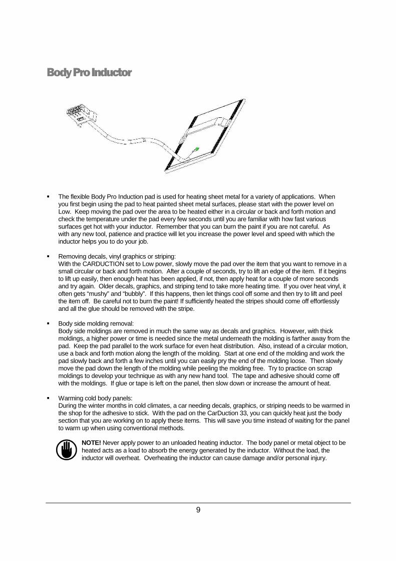
� The flexible Body Pro Induction pad is used for heating sheet metal for a variety of applications. When
you first begin using the pad to heat painted sheet metal surfaces, please start with the power level on Low. Keep moving the pad over the area to be heated either in a circular or back and forth motion and check the temperature under the pad every few seconds until you are familiar with how fast various surfaces get hot with your inductor. Remember that you can burn the paint if you are not careful. As with any new tool, patience and practice will let you increase the power level and speed with which the inductor helps you to do your job.
� Removing decals, vinyl graphics or striping:
With the CARDUCTION set to Low power, slowly move the pad over the item that you want to remove in a small circular or back and forth motion. After a couple of seconds, try to lift an edge of the item. If it begins to lift up easily, then enough heat has been applied, if not, then apply heat for a couple of more seconds and try again. Older decals, graphics, and striping tend to take more heating time. If you over heat vinyl, it often gets “mushy” and “bubbly”. If this happens, then let things cool off some and then try to lift and peel the item off. Be careful not to burn the paint! If sufficiently heated the stripes should come off effortlessly and all the glue should be removed with the stripe.
� Body side molding removal:
Body side moldings are removed in much the same way as decals and graphics. However, with thick moldings, a higher power or time is needed since the metal underneath the molding is farther away from the pad. Keep the pad parallel to the work surface for even heat distribution. Also, instead of a circular motion, use a back and forth motion along the length of the molding. Start at one end of the molding and work the pad slowly back and forth a few inches until you can easily pry the end of the molding loose. Then slowly move the pad down the length of the molding while peeling the molding free. Try to practice on scrap moldings to develop your technique as with any new hand tool. The tape and adhesive should come off with the moldings. If glue or tape is left on the panel, then slow down or increase the amount of heat.
� Warming cold body panels:
During the winter months in cold climates, a car needing decals, graphics, or striping needs to be warmed in the shop for the adhesive to stick. With the pad on the CarDuction 33, you can quickly heat just the body section that you are working on to apply these items. This will save you time instead of waiting for the panel to warm up when using conventional methods.
NOTE! Never apply power to an unloaded heating inductor. The body panel or metal object to be heated acts as a load to absorb the energy generated by the inductor. Without the load, the inductor will overheat. Overheating the inductor can cause damage and/or personal injury.

Bolt Pro Inductor
10
� The Bolt Pro inductor is used for intense heating of rusted or stuck parts such as nuts and bolts. When
using the Bolt Pro tip to loosen stuck nuts and bolts, it is OK to use full power to start with. Other uses include caulking removal from truck beds and trunks of sedans, as well as soldering large electrical connectors and metal forming.
� Removing stuck or rusted bolts:
The Bolt Pro is particularly useful in removing stuck or rusted nuts and bolts. It is better than an oxy-acetylene torch in several ways: 1. It heats only the metal parts positioned within the gap and without flames that can set fire to the
many plastic parts in today’s cars. Thus, reduced fire hazards. 2. Unlike the torch which tends to heat both the nut and the bolt, the Bolt Pro can be applied to the nut
only, heating it and making it expand more than the bolt and thus easier to break loose. 3. The Bolt Pro plugs into the CarDuction 33, it is light weight and portable, and ready for instant use. 4. It is not necessary to heat fasteners to a red color. In most cases, only mild heat is required to free
the seized fastener. Prolonged exposure of the Bolt Pro Inductor to extreme heat will shorten the life of the inductor, and could cause un-warranted damage.
5. It is recommended to maintain an air gap between the bolt pro inductor and the part being heated. A small piece of welding blanket or fiberglass cloth can be placed over the jaws of the Bolt Pro Inductor to help shield it from the radiated heat from the fastener, as well as protect it from accidental contact with a hot part. If the Bolt Pro inductor is in contact with the hot part, it could cause un-warranted damage. The maximum temperature allowed for he inductor is 150°.
� Bending metal parts:
� The Bolt Pro can also be used to rapidly bend small round or flat steel stock for most any purpose. � Soldering large electrical connectors.
� First crimp the connector to the wire � Place the barrel of the connector in the corner of the jaws of the Bolt Pro Inductor. � Apply heat by depressing the foot switch. � Apply solder once sufficiently heated
� Shrinking sheet metal: Place the end of the Bolt Pro tip onto the area of the sheet metal to be shrunk. Leave a small gap between the tip and the sheet metal if possible. This will help extend the life of the tip. Activate the switch and heat the metal to your liking. Tap the high spot down and cool. Grind area clean prior to shrinking to help eliminate toxic fumes and smoke.
NOTE! Never apply power to an unloaded heating inductor. The body panel or metal object to be
heated acts as a load to absorb the energy generated by the inductor. Without the load, the inductor will overheat. Overheating the inductor can cause damage and/or personal injury. The
Bolt Pro inductor shall not be in contact with hot parts for tool long time (temperature max 150 °C).

Glass Pro Inductor
11
Removing a window
1. Remove a reveal molding, if applicable. Some windows have encapsulated moldings that can not be removed. Encapsulated windows can also be removed without damage since the CarDuction only heats metal objects. Some windows have metal moldings, which need to be removed prior to applying heat with the CarDuction. The CarDuction will heat the metal nearest to the Glass Pro Inductor or other heating heads. If the metal trim can’t be removed, it will be necessary to heat the pinch weld from inside the vehicle.
2. Although not always necessary, it is recommended that the interior trim be removed from the vehicle to minimize the possibility of burning the trim. Removal of the interior trim also exposes any additional hardware such as clips and studs that may be holding the window in place. Such hardware will need to be released prior to the removal process. Locating the position of the urethane bead is also easier with the interior trim remvoved.
3. Disconnect antennas and defroster grids. 4. To prevent scratches to the painted surface that could be caused by wooden or plastic wedges,
place a layer of masking tape around the perimeter of the painted surface as close as possible to the glass or molding.
5. Place a clean layer of masking tape over the pole pieces of the Glass Pro Inductor to prevent scratching the glass as the Glass Pro is moved back and forth over the glass. Replace the tape every time another glass is to be removed.
6. Clean the glass thoroughly before starting the removal process 7. Always start the removal process near the area of the vehicle where the repair is to be made. The
greatest risk of paint damage by the wedges is at the starting point of the glass removal due to the difficulty of getting the first wedge in place. It’s best to start in a corner if possible and progress around the window towards the undamaged area of the vehicle.
8. Ideally the Glass Pro Inductor should be placed directly on top of the urethane for efficient window removal. However, some vehicles have narrow pinch welds that cause the Glass Pro Inductor to be too close to the painted surface, putting unnecessary heat into the area possibly burning the paint. In some cases a damp towel or heat sink compound may need to be applied to absorb the heat being put into the painted surface. (See illustrations) If possible, keep the heating attachment at least 1 inche away from the edge of painted surface.
9. Generally the urethane is located at the inner edged of the pinch weld. To locate the pinch weld, place hand piece of Glass Pro on inner side of window about 4” away, parallel to the edge or flange of window opening.
10. Set the unit to maximum output then turn the unit on and notice the indicator on the meter located on the top of the unit. It will move slightly above zero. Slowly move hand piece toward the outer edge of the window (maintain parallel orientation of attachment to edge of glass) and monitor the meter as doing so. The meter will begin to increase as you move closer to the pinch weld. The more metal that is near the heating attachment, the higher the meter will read. Maximum output from the unit is approximately 7 on the meter (The maximum value is affected by they type of metal and thickness of the metal). It is not necessary to max out the meter. Once the meter starts to increase from its nominal position, move another ¼” (6mm) closer to the edge. The heating attachment should be located over the edge of the pinch weld while maintaining maximum distance from the painted surface. Visually note the distance between the edge of the glass and
Glass Pro Inductor
12
the heating attachment. Maintain the distance as you progress around the window. 11. As previously stated it is best to start in a corner on the same side of the vehicle where the repair
will be made. Start by moving the heating attachment back and forth about 12 inches on each side of a corner at a rate of about ½ inch per second. Heating too much of an area is ineffective because it reduces the amount of heat produced in the pinch weld. Make about 4 passes over the corner. A light trail of vapor/smoke should be visible by this time. Heavy smoke is not good, stop the process and inspect the vehicle to determine the cause of smoke. Do not breath the vapors. An external air supply respirator is recommended. Hydrogen Cyanide gas is emitted from the hot urethane, which can be poisonous.
12. Once the vapor is visible, you are at the optimal temperature for the urethane to release. Gentle outward pressure is required to break the bond. It is possible for it to take several minutes to break the initial bond of the urethane. Once the bond is broken, the urethane will not re-bond with the metal. A suction cup can be used in the corner to provide a location for pulling the glass as the pinch weld is heated. Once the corner is lifted, a plastic wedge, such as the CarDuction glass wedges can be inserted behind the glass. The wedges provide outward force while heating, allowing for one man removal of the glass. Be careful. Do not put too much pressure on the glass, or it will break. Front glass is laminated and is easily cracked. Side and rear glass are tempered and much more durable. Start with rear or side glass first then progress to windshields as you gain experience. It’s best to practice on salvage or totaled vehicles first to get familiar with the techniques.
13. Add wedges or reposition other wedges as you move around the glass. Tempered glass can withstand some prying without breaking. If a prying action is used, it is best to pry away from the car to prevent unnecessary paint damage that could occur if pressure is applied to the paint with the wedge by prying in the opposite direction. Constant outward pressure is necessary to allow the window to release at the lowest possible temperature. See illustrations and notes on the next pages for additional information.
14. Typical removal time for small quarter glass is around 3 to 5 minutes. 10 minutes is not uncommon. Typical removal time for rear glass and SUV side glass is around 10 to 20 minutes. Front Glass can be removed in as little at 15 minutes, but some larger vehicles require up to an hour to remove front glass.
� Removing bonded composite panels to metal, i.e. Camero/Firebird roofs:
Gently place a wood or plastic wedge between the inner and outer panel to be separated. Looking at the panel from a side angle you will begin to notice a slight dimple in the panel, stop, this should be enough, begin to work the Glass Pro hand piece over this dimple in a circular motion applying even heat to the general area. Once this dimpled area releases, push the wedge in until you see the next dimple and repeat. Continue to do so until you reach your objective.
NOTE! Never apply power to an unloaded heating inductor. The body panel or metal object to be heated acts as a load to absorb the energy generated by the inductor. Without the load, the inductor will overheat. Overheating the inductor can cause damage and/or personal injury.

Glass Pro Inductor
13
Glass Removal Illustration
NOTES:

Glass Pro Inductor
14

Magnepopper Inductor
15
� The Magnepopper heating inductor’s (optional accessory) primary use is for paintless dent repair
and metal shrinking. The Magnepopper emits a strong magnetic field at the tip of the inductor approximately ½” (13mm) in diameter. The strong focused field from the Magnepopper makes it possible to remove soft dents of all sizes without damaging the paint. The Magnepopper can eliminate the need to hire a PDR technician in many cases, saving the shop hundreds of dollars per car.
� It is not necessary to remove the interior trim, because all the work can be conducted from the outside of the vehicle. Additionally, the risk of damage to the interior is minimal because most dents are removed at temperatures less than 150F (66C). However, the interior trim should be removed if metal shrinking is to be conducted, due to the higher temperature requirements.
� It is not necessary to drill holes in panels when using the Magnepopper because all the work is done from the outside of the vehicle.
� Although, the Magnepopper does not produce any heat, it is possible to burn the paint if left in one position for too long. Approximately 3 seconds is the maximum amount of time the Magnepopper can be held in one location before paint is burned.
� The Magnepopper removes dents based on the principles of thermal expansion. The magnetic field when placed over a dented area causes the metal in that area to become hot. Metal expands as it gets hot. The surrounding cooler metal constrains the outside of the dented area that is being heated. The heat causes the dent to expand upward, thus removing the dent.
� In some cases, the dent will increase in size when heated. If this occurs, move out to the outer edge of the dent and heat again. Continue to move outward until the dent starts to decrease in size. Large dents and swells required a circular motion starting at the perimeter of the dent, progressing to the middle.
� It is possible and recommended to over raise the dented area with the Magnepopper inductor. Over raising the dent stretches the metal in the opposite direction, which prevents the dent from reappearing when it cools. The area that is over raised will flatten when cooled. It may be necessary to tap the high area down in some cases.
� After raising the dented area, immediately quench the spot with a spray bottle or damp cloth. This will reduce the likely hood of the metal having memory.
� When working panels with many dents, users should not work in one area, but rather move around the panel heating one area while another cools. This will prevent an oil can effect which could permanently distort the metal.
� Do not over work a dent, because paint damage can occur. 3 to 5 seconds cumulative heat time is all the paint can withstand before being burned. After heating 3 to 5 seconds, cool the area thoroughly before heating again. Each time the dent is heated and quenched it is raised a little more
� Dents with creases in them are more difficult. The Magnepopper inductor can remove the dent, but in most cases the crease is still visible, but can be covered with a little high-build primer and block sanding.
� Dents near the edge of panels or near mechanical details like corners and rain channels are very difficult to remove with the Magnepopper inductor. Traditional PDR techniques may have to be employeed.

Magnepopper Inductor
16
� The Magnepopper can also be used for heating seized nuts in difficult to reach areas, as well as heating bearings for thermal expansion prior to installation.
NOTE! Never apply power to an unloaded heating inductor. The body panel or metal object to be heated acts as a load to absorb the energy generated by the inductor. Without the load, the inductor will overheat. Overheating the inductor can cause damage and/or personal injury.

Routine Maintenance
17
ROUTINE MAINTENANCE � The fault indicator will illuminate due to the following reasons:
� Shorted or overheated induction heating coil. � Internal damage to the power source. � If the CarDuction is used in a dusty environment, remove the top cover and blow out the
interior of the cabinet once every 2 months � If the CarDuction is routinely transported from site to site, remove the top cover, inspect and/or
tighten all fasteners within the cabinet. Although the Autron has been thoroughly tested for transit, fasteners can become loose and cause possible damage due to overheating and/or short circuits.
� Listen for the operation of the internal cooling fans and very adequate air flow from the louvers located
on the side of the power source. � Frequently inspect all input power cables, as well as all inductor and foot switch cables for signs of
wear. Do this daily. Replace or repair cables as needed � Disconnect input power and tighten all internal electrical connections every 6 months. Heating and
cooling of the electrical components from normal use will cause electrical connections to loosen over time and reduce the consistency of the system.
� Inspect the integrity of the HF output connector pins and the pins inside the HF connectors of the
heating inductors once per month. Make sure that all contacts are properly aligned and show no signs of arcing or burns. Replace the inductors immediately if signs of damage are present. Return the power supply to the factory for service is damage is detected.


