42
Car Monitoring System Team IPA Kirill Belyayev Amjad Chaudhry Arush Dhawan Aditya Kaundinya Bilal Yousufi
| Date post: | 21-Dec-2015 |
| Category: |
Documents |
| View: | 215 times |
| Download: | 0 times |

Car Monitoring SystemTeam IPA
Kirill Belyayev
Amjad Chaudhry
Arush Dhawan
Aditya Kaundinya
Bilal Yousufi

Introduction and Development Kit
Amjad Chaudhry

In-Car Automation and In-Car Automation and Monitoring SystemMonitoring System
• Sensors are placed throughout a car that Sensors are placed throughout a car that wirelessly send data back to a central wirelessly send data back to a central terminalterminal– Data displayed on LCDData displayed on LCD– Zigbee is used to transmit and receive DataZigbee is used to transmit and receive Data– Visual Warnings will be given if a sensor Visual Warnings will be given if a sensor
detects something has fallen below the detects something has fallen below the threshold.threshold.

ImplementationImplementation
• We will use Zigbee technology to measure different We will use Zigbee technology to measure different components of a car and display the data on a main components of a car and display the data on a main LCD screen. LCD screen. – Tire PressureTire Pressure– TemperatureTemperature– Accelerometer Accelerometer – Proximity SensorProximity Sensor– Car Battery VoltageCar Battery Voltage
• If any of the sensors detect a critical level our system If any of the sensors detect a critical level our system will be used to provide a visual warning to the driver. will be used to provide a visual warning to the driver.

Project Outline
-A /D C on v e rte rs S e n s o rs
S e n so r B o a rds
R x T x
Z igb eeC o m m u n ic a tion
L C D K e yp ad
M a in B o a rd
S o ftw a reIm p le m e n ta tion
M a in B o a rd S e n so r B o a rds
H a rd w a reD e s ign
M a in B o a rd S e n so r B o a rds
P C BD e s ign

Division of Labor
• Aditya and Amjad will work solely on software issues– A/D Converter– Zigbee Communication
• Kirill – Mainboard Design– Hardware/Software Implementation
• Will also work with Aditya and Amjad, with software implementation of hardware (I.e. LCD, Keypad, RS-232, User Interface)
• Arush and Bilal – Sensors’ schematic and design– PCB for Main Board and Sensors

Parking Sensors
Tire Pressure Sensors
Accelerometer Sensor
Temperature sensors
Battery voltage sensors
LCD Screen
Keypad Speaker
Main Terminal
System ArchitectureSystem Architecture

Development Kit•Our development kit came with a programming environment, CodeWarrior. The kit also came with demo applications to be tested with our board to introduce the user to programming for RF applications.
•The board has:
•Two accelerometers, four switches and LEDs, a MC13192 transceiver, printed antenna, serial interface and MC9s08GT60 low-power MCU with 60KB of flash memory.


Software
Aditya Kaundinya

Software Overview
Zigbee Communication• Simple Media Access Controller Functions•ANSI C based code used for developing RF applications.
A/D Converter Implementation• Used to convert continuous signals to digital numbers. •The digital output can take different arithmetic forms. (Binary, Hexadecimal, etc.)

Demo Software
• Our development kit came with demo code that allowed us to test our hardware.
• -Range Finder – Code that adjusted the number of blinking LED’s respective to the distance between the two boards.
• -UART Demo – Wireless transmits a user’s keystrokes to the terminal of another pc using the Zigbee transceivers.

Example Code (Range Detection)TRANSMIT STATE - case TX_STATE: /*Load the tx buffer with the ZigBee packet.*/ au8TxDataBuffer[0] = 'Z'; au8TxDataBuffer[1] = 'i'; au8TxDataBuffer[2] = 'g'; au8TxDataBuffer[3] = 'B'; au8TxDataBuffer[4] = 'e'; au8TxDataBuffer[5] = 'e'; sTxPacket.u8DataLength = 6; if (MCPSDataRequest(&sTxPacket) == SUCCESS) MLMERXEnableRequest(&sRxPacket,DELAY_COUNT);
RECEIVE STATE - case RX_STATE: MLMERXEnableRequest(&sRxPacket,0); break;

SMAC FunctionsMLMESetMC13192OutputAdjust
Adjusts the output power of the transmitter(0-15)
MLMEHibernateRequest Disables Clock Output
MLMEWakeRequest Brings radio out of low power mode
MLMERXEnableRequest Places radio in receive mode
sRxPacket->pu8Data[3] Reads power value from third byte of data packet
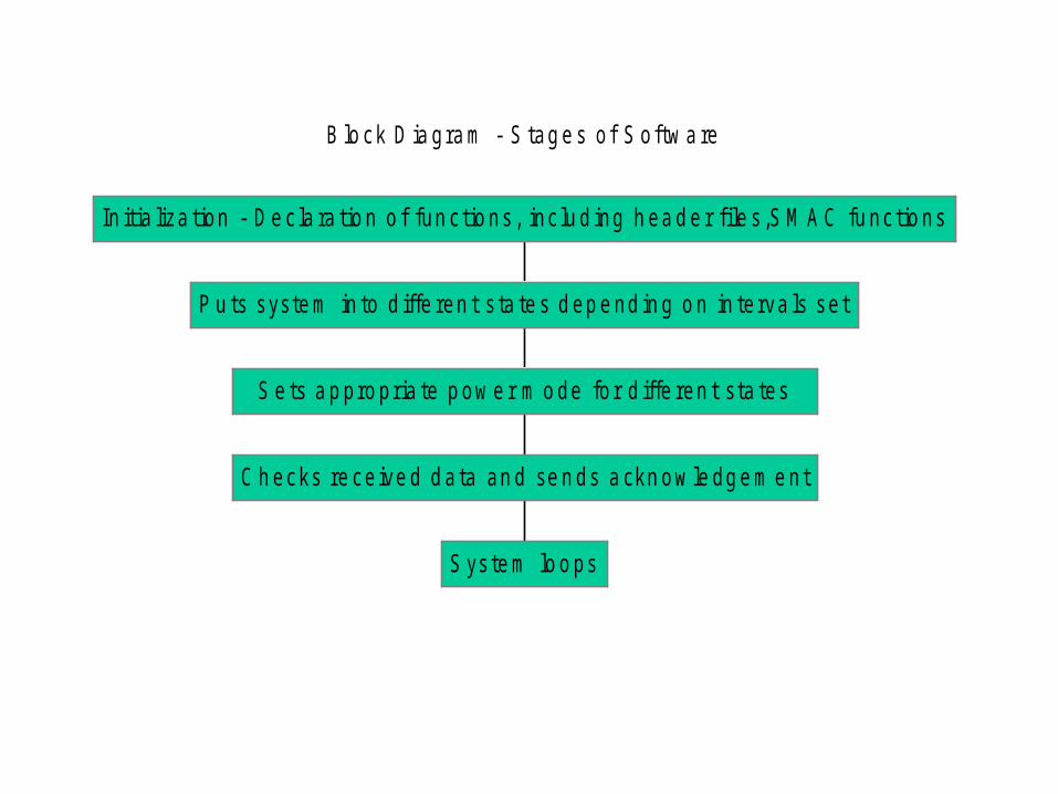
B lo ck D ia gra m - S tag e s o f S o ftw a re
S ys te m lo o ps
C h ecks re ce ive d d a ta an d se n ds a ckn ow le dg e m e nt
S e ts a p pro pria te p ow e r m o de fo r d iffe ren t sta tes
P u ts syste m in to d iffe ren t s ta te s d ep e nd in g o n in te rva ls se t
In it ia liza tion - D e c la ra tio n o f fun c tio ns , inc lu d ing h ea d e r f ile s ,S M A C fu nc tio ns

A-D Converter•Tire pressure sensor gives an analog voltage value.
• The output pin of the sensor is connected to one of the 8 A-D converter pins on the microcontroller.
•The voltage signal from the sensor is converted to a binary number using the microcontroller.
•The voltage-pressure relation below is used to convert the digital value into the corresponding pressure value.

Immediate Software GoalsGoal 1 – by 03/03/2008•Understand all the SMAC functions by next Monday.• Simultaneously work on writing code to control LED’s using the pushbuttons.Goal 2 – by 03/15/2008• Connect tire pressure sensor to the A/D converter on the development board.• Write software to output the correct air pressure from the A/D converter.

Main Board
Kirill Belyayev

Main Board Schematic
RxD
KB0
TxD
SS2
KB1
SS2
KB2
Title
Size Document Number Rev
Date: Sheet of
Made by IPA Team 1.0
Main Terminal Schematic
B
1 1Monday, February 25, 2008
KB3
/CS1
SO2
/WP3
GND4
VCC8
/HOLD7
SCK6
SI5
U18
IS25C64A
R185K
3.3V
LCD_A2LCD_A1LCD_A0
C1310.5pF
ATTNB
L1016.8nH
TP102
C102100nF
TP103
C130100pF
KB4KB3
ANT101
KB6KB5
TP101
IRQ
R105
470K
CLKO
123456
J101
2*3pANT102
0.1uFC23
BDM PORT
LCD_RES
X101
16.000MHz
LCD_D1LCD_D0
C1056.8pF
LCD_D3LCD_D2
MOSI
C1066.8pF
LCD_D5LCD_D4
C107220pF
LCD_D7LCD_D6
SPICLK
C104100nF
VDDA
W102EL=22.5 deg, Z=120ohm
W103EL=58 deg, Z=120ohm
W104EL=58 deg, Z=120ohm
TxD
W101EL=22.5 deg, Z=120ohm
S106
Switch SPST SMD
SW5
C1280.5pF
C12618pF
C12718pF
RESET Switch
C103100nF
R106220RNot Mounted
ATTNBi14
CEBi19
CLKOo15
GPIO111
GPIO210
GPIO39
GPIO48
GPIO725
GPIO523
GPIO624
IRQBo20
MISOo18
MOSIi17
PAO_M6
PAO_P5
RIN_M1
RIN_P2
RSTBi12 RXTXENi13
SM7
SPICLKi16
TINJ_M4
TINJ_P3
XTAL126
XTAL227
VBATT31
VDDA32
VDDD21
VDDINT22
VDDLO129
VDDLO228
VDDVCO30
GND33
IC101
MC13192
C129
100nF
GPIO1
SS
GPOI2
IRQ11
PTA0/KBIP032
PTA1/KBIP133
PTA2/KBIP234
PTA3/KBIP335
PTA4/KBIP436
PTA5/KBIP537
PTA6/KBIP638
PTA7/KBIP739
PTB0/AD022
PTB1/AD123
PTB2/AD224
PTB3/AD325
PTB4/AD426
PTB5/AD527
PTB6/AD628
PTB7/AD729
PTC0/TxD22
PTC1/RxD23
PTC2/SDA4
PTC3/SCL5
PTC46
PTC57
PTC68
PTD0/TPM1CH018
PTD1/TPM1CH119
PTD3/TPM2CH020
PTD4/TPM2CH121
PTE0/TxD19
PTE1/RxD110
PTE2/SS12
PTE3/MISO13
PTE4/MOSI14
PTE5/SPSCK15
PTG0/BKGD/MS42PTG1/XTAL43PTG2/EXTAL44
RESET1
VDD17
VDDAD40
VREFH30
VREFL31
VSS16
VSSAD41
IC102
MC9S08GT60
MISO
RSTB
KB1KB0
RXTXEN
KB2
3V0
3V0
3V03V0
4.5mm
11.5mm11.5mm
4.5mm
C108220pF
GPIO2GPIO1
/RST18
WDI8
/RSTIN19
/RSTIN210
Vss14
Vcc28
/E27
/IRQ/FT/OUT26
THS23
SDI17
SQW1
SCL20
SDO16
NC25
NC24
NC22
NC21
NC19
NC15
NC2
NC3
NC4
NC5
NC6
NC7
NC11
NC12
NC13
U19
M41T94MH
MISO
MOSI
R145K
R155K
C109100nF
R165K
R175K
KP01
KP12
KP23
KP34
5KP
4
KP5
6
KP6
7
1 2 3
4 5 6
7 8 9
0* #
U14
KeypadSPICLK
3.3V
3.3V
MOSIMISO
3.3V3.3V
SPICLK
3.3V
SS3
KB4
VCC16
R1IN13
R2IN8
T2IN10
T1IN11
C1+1
C1-3
C2+4
C2-5
R1OUT12
R2OUT9
T1OUT14
T2OUT7
V+2
V-6
U12
MAX3232
0.1uF
C18
SS3
0.1uF
C19
0.1uFC20
0.1uFC21
0.1uFC22
594837261
P6CONNECTOR DB9
LCD_A3
KB5
0.1uFC24
3.3V
GPIO1GPOI2
KB6
RxD
3.3V

Microprocessor
LCD_A2LCD_A1LCD_A0
KB4KB3
KB6KB5
LCD_RES
LCD_D1LCD_D0
LCD_D3LCD_D2
LCD_D5LCD_D4
LCD_D7LCD_D6
IRQ11
PTA0/KBIP032
PTA1/KBIP133
PTA2/KBIP234
PTA3/KBIP335
PTA4/KBIP436
PTA5/KBIP537
PTA6/KBIP638
PTA7/KBIP739
PTB0/AD022
PTB1/AD123
PTB2/AD224
PTB3/AD325
PTB4/AD426
PTB5/AD527
PTB6/AD628
PTB7/AD729
PTC0/TxD22
PTC1/RxD23
PTC2/SDA4
PTC3/SCL5
PTC46
PTC57
PTC68
PTD0/TPM1CH018
PTD1/TPM1CH119
PTD3/TPM2CH020
PTD4/TPM2CH121
PTE0/TxD19
PTE1/RxD110
PTE2/SS12
PTE3/MISO13
PTE4/MOSI14
PTE5/SPSCK15
PTG0/BKGD/MS42PTG1/XTAL43PTG2/EXTAL44
RESET1
VDD17
VDDAD40
VREFH30
VREFL31
VSS16
VSSAD41
IC102
MC9S08GT60
KB1KB0
KB2
C109100nF
3.3V
LCD_A3
MC9S08GT60
Six Different General I/O Ports:
• Port A has keyboard interrupts
• Port B has A/D Converter inputs
• Port C has SCI2 and I2C interfaces
• Port D has Timer/PWM module
• Port E has SCI1 and SPI interfaces

RF Data Modem
ATTNBi14
CEBi19
CLKOo15
GPIO111
GPIO210
GPIO39
GPIO48
GPIO725
GPIO523
GPIO624
IRQBo20
MISOo18
MOSIi17
PAO_M6
PAO_P5
RIN_M1
RIN_P2
RSTBi12 RXTXENi13
SM7
SPICLKi16
TINJ_M4
TINJ_P3
XTAL126
XTAL227
VBATT31
VDDA32
VDDD21
VDDINT22
VDDLO129
VDDLO228
VDDVCO30
GND33
IC101
MC13192
MC13192
• SPI pins for on-board communication
• RF input/output pins
• General purpose I/O pins
• Interrupt, Reset, Rx/Tx Enable pins
• External clock pins

Serial Communication Interface
Max3232 – SCI Driver and Receiver

Keypad
KB0
KB1
KB2
KB3
R145K
R155K
R165K
R175K
KP01
KP12
KP23
KP34
5KP
4
KP5
6
KP6
7
1 2 3
4 5 6
7 8 9
0* #
U14
Keypad
3.3V3.3V3.3V3.3V KB4 KB5 KB6
• 12 Keys – 7 pins
• Rows have pull up resistors and used as outputs
• Columns used as inputs

LCD Interface
LCD_A1
NC1
FR2
CL3
/DOF4
/CS15
CS26
/RES7
A08
R/W9
E10
D011
D112
D213
D314
D415
D516
D617
D718
VDD19
VSS20
VOUT21
C3-22
C1+23
C1-24
C2-25
C2+26
V127
V228
V329
V430
V531
VR32
C8633
P/S34
NC35
NC36
U26
NJU6676 Master
NC1
FR2
CL3
/DOF4
/CS15
CS26
/RES7
A08
R/W9
E10
D011
D112
D213
D314
D415
D516
D617
D718
VDD19
VSS20
VOUT21
C3-22
C1+23
C1-24
C2-25
C2+26
V127
V228
V329
V430
V531
VR32
C8633
P/S34
NC35
NC36
U27
NJU6676 Slave
LCD_D1LCD_D0
LCD_D3LCD_D2
LCD_D4LCD_D5
LCD_D7LCD_D6
LCD_A2
V1 V1V2
LCD_A2LCD_A1LCD_A0
LCD_D1LCD_D0
LCD_D3LCD_D2
LCD_D5LCD_D4
LCD_D7LCD_D6
V2V3
LCD_RES
V3V4
LCD_RES
V4V5 V5
R1265K
3.3V
LCD_A0
LCD_MCS
R1335K
3.3V
LCD_SCS
R1255K
R1315K
R1345K
3.3V
3.3V3.3V
3.3V
R1325K
3.3V
3.3V
Two NJU6676 Drivers
• 64x132 pixels each
• Parallel or Serial
• Internal power supply circuit (not used)

Sensor Schematics
Arush Dhawan

Sensor Schematic
• Tire Pressure Chip - MPX4250– Operates at 5V
• Max Input of MC9S08 is 3.6V– Attenuator– Readjust Transfer Function in Software
– Sensor Chips are interchangeable, the only thing that will need to be adjusted the attenuator and software.
• Temperature – FM20P5X – 3.3V• X-Y Accelerometer – MMA1260D - 5 V• Z Accelerometer – MMA6261Q 3.3V• Proximity Sensor – Sharp GP2Y0A21YK - 3.3V

Tire Pressure Chip
5.1V
KB3KB4
KB6KB5
IRQ11
PTA0/KBIP032
PTA1/KBIP133
PTA2/KBIP234
PTA3/KBIP335
PTA4/KBIP436
PTA5/KBIP537
PTA6/KBIP638
PTA7/KBIP739
PTB0/AD022
PTB1/AD123
PTB2/AD224
PTB3/AD325
PTB4/AD426
PTB5/AD527
PTB6/AD628
PTB7/AD729
PTC0/TxD22
PTC1/RxD23
PTC2/SDA4
PTC3/SCL5
PTC46
PTC57
PTC68
PTD0/TPM1CH018
PTD1/TPM1CH119
PTD3/TPM2CH020
PTD4/TPM2CH121
PTE0/TxD19
PTE1/RxD110
PTE2/SS12
PTE3/MISO13
PTE4/MOSI14
PTE5/SPSCK15
PTG0/BKGD/MS42PTG1/XTAL43PTG2/EXTAL44
RESET1
VDD17
VDDAD40
VREFH30
VREFL31
VSS16
VSSAD41
IC104
MC9S08GT60
KB1KB0
KB2
GPIO1GPOI2
GPIO1GPIO2
C117100nF
3.3V
R109
5k R11010k
Vout1GND2Vs3NC4NC5NC6
U18
MPX4250

Temperature Chip
3.3V
KB3KB4KB5KB6
IRQ11
PTA0/KBIP032
PTA1/KBIP133
PTA2/KBIP234
PTA3/KBIP335
PTA4/KBIP436
PTA5/KBIP537
PTA6/KBIP638
PTA7/KBIP739
PTB0/AD022
PTB1/AD123
PTB2/AD224
PTB3/AD325
PTB4/AD426
PTB5/AD527
PTB6/AD628
PTB7/AD729
PTC0/TxD22
PTC1/RxD23
PTC2/SDA4
PTC3/SCL5
PTC46
PTC57
PTC68
PTD0/TPM1CH018
PTD1/TPM1CH119
PTD3/TPM2CH020
PTD4/TPM2CH121
PTE0/TxD19
PTE1/RxD110
PTE2/SS12
PTE3/MISO13
PTE4/MOSI14
PTE5/SPSCK15
PTG0/BKGD/MS42PTG1/XTAL43PTG2/EXTAL44
RESET1
VDD17
VDDAD40
VREFH30
VREFL31
VSS16
VSSAD41
IC106
MC9S08GT60
KB0KB1KB2
GPIO1 GPIO1
GPOI2GPIO2
C125100nF
3.3V
NC1
GND2
Vout3
VDD4
GND5
U21
FM20T

Z Accelerometer Chip
IRQ11
PTA0/KBIP032
PTA1/KBIP133
PTA2/KBIP234
PTA3/KBIP335
PTA4/KBIP436
PTA5/KBIP537
PTA6/KBIP638
PTA7/KBIP739
PTB0/AD022
PTB1/AD123
PTB2/AD224
PTB3/AD325
PTB4/AD426
PTB5/AD527
PTB6/AD628
PTB7/AD729
PTC0/TxD22
PTC1/RxD23
PTC2/SDA4
PTC3/SCL5
PTC46
PTC57
PTC68
PTD0/TPM1CH018
PTD1/TPM1CH119
PTD3/TPM2CH020
PTD4/TPM2CH121
PTE0/TxD19
PTE1/RxD110
PTE2/SS12
PTE3/MISO13
PTE4/MOSI14
PTE5/SPSCK15
PTG0/BKGD/MS42PTG1/XTAL43PTG2/EXTAL44
RESET1
VDD17
VDDAD40
VREFH30
VREFL31
VSS16
VSSAD41
IC104
MC9S08GT60
KB1KB0
KB2
GPIO1GPOI2
GPIO1GPIO2
C117100nF
3.3V
R109
5k R11010k
Vss1
Vss2
Vss3
Vout4
STATUS5
VDD6
Vss7
ST8
NC16
NC15
NC14
NC13
NC12
NC11
NC10
NC9
U1
XYACC
5.1V
KB3KB4
KB6KB5

X-Y Accelerometer
KB4KB5KB6
C158
.1uF
IRQ11
PTA0/KBIP032
PTA1/KBIP133
PTA2/KBIP234
PTA3/KBIP335
PTA4/KBIP436
PTA5/KBIP537
PTA6/KBIP638
PTA7/KBIP739
PTB0/AD022
PTB1/AD123
PTB2/AD224
PTB3/AD325
PTB4/AD426
PTB5/AD527
PTB6/AD628
PTB7/AD729
PTC0/TxD22
PTC1/RxD23
PTC2/SDA4
PTC3/SCL5
PTC46
PTC57
PTC68
PTD0/TPM1CH018
PTD1/TPM1CH119
PTD3/TPM2CH020
PTD4/TPM2CH121
PTE0/TxD19
PTE1/RxD110
PTE2/SS12
PTE3/MISO13
PTE4/MOSI14
PTE5/SPSCK15
PTG0/BKGD/MS42PTG1/XTAL43PTG2/EXTAL44
RESET1
VDD17
VDDAD40
VREFH30
VREFL31
VSS16
VSSAD41
IC108
MC9S08GT60
KB0KB1KB2
GPIO1 GPIO1
GPOI2GPIO2
C157100nF
3.3V
R115
1K
R116
1K
C159.1uF
C160.1uF
NC
1N
C2
VD
D3
Vss
4
NC5
NC6
NC7
NC8
ST
12N
C11
NC
10N
C9
NC16
Xout15
Yout14
NC13
U22ZACC2
3.3V
KB3

Proximity Sensor
KB3KB4KB5KB6
Vo1
GND2
Vcc3
U23
PROX2
IRQ11
PTA0/KBIP032
PTA1/KBIP133
PTA2/KBIP234
PTA3/KBIP335
PTA4/KBIP436
PTA5/KBIP537
PTA6/KBIP638
PTA7/KBIP739
PTB0/AD022
PTB1/AD123
PTB2/AD224
PTB3/AD325
PTB4/AD426
PTB5/AD527
PTB6/AD628
PTB7/AD729
PTC0/TxD22
PTC1/RxD23
PTC2/SDA4
PTC3/SCL5
PTC46
PTC57
PTC68
PTD0/TPM1CH018
PTD1/TPM1CH119
PTD3/TPM2CH020
PTD4/TPM2CH121
PTE0/TxD19
PTE1/RxD110
PTE2/SS12
PTE3/MISO13
PTE4/MOSI14
PTE5/SPSCK15
PTG0/BKGD/MS42PTG1/XTAL43PTG2/EXTAL44
RESET1
VDD17
VDDAD40
VREFH30
VREFL31
VSS16
VSSAD41
IC110
MC9S08GT60
KB0KB1KB2
GPIO1 GPIO1
GPOI2GPIO2
C174100nF
3.3V
3.3V

PCB Design and Logistics
Bilal Yousufi

PCB Design – Revision 1
• Altium Designer
• 1st Revision by March 1st
• R– 2 Boards
• Mainboard– Power Source: 12V Battery with DC-DC Buck Converter.
» Components Operate between 3.3V – 12V
• Tire Pressure Board

PCB Design – Revision 2
• 2nd Revision by Milestone 2– Mainboard– Tire Pressure, Temperature, 3-axis Accelerometer Board, and more if time permits
• Sensor Boards will be powered by batteries.– We will try to lower power consumption as much as possible– Test Power Consumption, based on transmission intervals
• Ruggedized Casing
– RF Data Modem
• 3rd Revision by Expo– More Sensors (Voltage or Fluid Level)– More Mainboard Functions
• Storage• Color LCD
• 4 Layer Boards from 4pcb.com– Routing on Outside– Inner Layers will be Voltage (3.3V) and Ground– A couple of Sensors use 5V, we might split the voltage layer, or use a boost converter.

Long Range RF Modem•Car – PC Link that can send Data (i.e. Racetrack, Test drive)
•40 Mile Range
•Monitor Sensor Data on Computer
•Will be implemented in the second revision of the design
•RS-232 Link (Already on Mainboard)
•Implementing Software will be the main issue
•We don’t have experience with creating packet structure

Power
• Mainboard– 3.3V, 5V– Input of 9V for 1st PCB Revision– Input of 12V for 2nd PCB Revision (Car Battery)
• Voltage Regulators to Step Down to 3.3V, and 5V• Boost Converter to 15 V
• Sensor– 3.3V Power Source– Converters for Sensor Chips

Power
5V3.3V
1uFC1
1
2
J1
R1390
In1
Gnd
25V
3
LP38690DTX-5.0U2
+ C210uF
SW1SPST
D5
1N4003
D6GREEN LED
D4
1N4003
D2
1N4003
D3
1N4003
D1
1N4003
Power jack2.1mm
In1
Gnd
2
5V3
LP38690DTX-3.3U3
+ C310uF
D7
1N4003
•Our first PCB Revision will not be wireless and have a 9V Source. We will be using the power adapters from our development kit.
•We will be using 9V with Voltage Regulators at 5V and 3.3V
•Our second PCB Revision will focus on power conservation, and the sensor modules will be run by batter

LCD Interface
COMP1
GND2
VIN3
EN4
IN5
VREF10
FB09
OUT08
PS_GND07
SW06
PW_P
AD
U28
TPS63700
R130100K
4 x 4.7uFC30
10pF
C31
R12710 0.1uF
C27
0.22uFC32
10uFC28
Vee-12V 150mA
3.3V
4.7nFC29 L106
10uH
D10
DIODE SCHOTTKY
R1281.2M
R129121K
•Proper Operation of LCD, needs 5 discreet voltages
•Voltages Range from 3.3V to –12V
•Logic – 3.3V
•GND – 0 V
•On/Off Voltages for LCD Pixels
•Bias Voltage is -12V (Pixels, Contrast)

Power - LCD Interface
3.3V
3.3V
3.3V
3.3V
3.3V
Vee
-7.7 to -11.2 V
Vee
Vee
3.3V
Vee
3.3V
3.3V
3.3V
3.3V
+ C121uF
3
21
411
-
+
U23A
LM324
5
67
411
-
+
U23B
LM324
10
98
411
-
+
U23C
LM324
12
1314
411
-
+
U23D
LM324
R1164.7K
R1184.7K
R11923.7K
V1
R1204.7K
R1214.7K
V2
V3
12
1314
411
-
+
U24D
LM324
V4
3.3V
+ C131uF
Vee
+ C141uF
+ C151uF
V5
Vee
+ C161uF
R12220.5K
R1231.44K
R12410K POT
Power Circuit for Display
•Adjusts Contrast
•On/Off Voltages for Pixels

Updated Timeline

Qnt Description M/N Part # Vendor Part # Vendor's Name Price of 1 On-board reference2 IC MCU 60K FLASH 20MHZ 44-QFP MC9S08GT60CFBE MC9S08GT60CFBE-ND Digikey $0.00 SAMPLED4 RF Data Modem MC13192FCR2 MC13192FCR2CT-ND Digikey $0.00 SAMPLED3 IC PLD 8CELL 3V 10NS SO20 ATF16LV8C-10SC ATF16LV8C-10SC-ND Digikey $2.695 IC SPI BUS SRL EEPROM 64K 8-SOIC IS25C64A-2GLI 706-1015-5-ND Digikey $1.162 IC RTC SPI SRAM SER 64X8 28-SOIC M41T94MH6F 497-5372-1-ND Digikey $5.802 IC SNAPHAT BATT/CRYSTAL 28-SOIC M4T28-BR12SH1 497-3686-5-ND Digikey $5.811 KEYPAD 12 KEY FRONT PANEL MNT 96AB2-102-F GH5001-ND Digikey $12.023 IC MCU 60K FLASH 20MHZ 44-QFP MC9S08GT60CFBE MC9S08GT60CFBE-ND Digikey $10.512 MPX4250 $0.00 SAMPLED
10 Voltage Regulators/Converters $10.00100 Res $0.10100 Caps $0.20
2 Speaker $10.0035 Switches $0.5030 LEDs $1.0020 Jacks, connectors $0.503 CONN DB9 FEMALE .590" R/A NICKEL 183-009-213R181 183-809FE-ND Digikey $3.943 IC DRVR/RCVR MULTCH RS232 16SOIC MAX3232CDWR 296-13095-1-ND Digikey $1.504 LED ARRAY 2X5MM 5-SEG YELLOW SSA-LXB525YD 67-1203-ND Digikey $1.601 LCD MOD GRAPH 240X64 WHT TRANSFL 73-1262-ND F-51851GNFJ-SLW-AEN Digikey $51.74
LCD Power Supply Components:3 IC CONV DC/DC INV MCRPWR SOT23-5 LT1617ES5#TRMPBF LT1617ES5#TRMPBFCT-ND Digikey 4.14
3 IC OP AMP QUAD LOW POWER 14-SOIC LM324M/NOPB LM324MNS-ND Digikey 1.023 POT 10K OHM 10MM 347 DEGREE SMD EVW-AE4001B14 P12426CT-ND Digikey 1.723 IC DC/DC INV -15V 10-SON TPS63700DRCT 296-18729-1-ND Digikey 4.163 INDUCTOR 10UH SHIELDED SMD CDRH5D18-100NC 308-1346-1-ND Digikey 0.923 DIODE SCHOTTKY 30V200MA SSMINI2P MA2SD3100L MA2SD3100LCT-ND Digikey 0.51
30 CAP .1UF 25V CERAMIC X7R 0603 C0603C104K3RACTU 399-1281-1-ND Digikey 0.11830 CAP CER 10UF 10V X7R 0805 GRM21BR71A106KE51L 490-3905-1-ND Digikey 0.54130 CAP CER 4.7UF 10V X7R 0805 LMK212BJ475KG-TR 587-1442-1-ND Digikey 0.28130 CAP CERM .22UF 16V X7R 0603 B37931K9224K60 495-1919-1-ND Digikey 0.04230 CAP CERM 10PF 10% 100V NP0 0603 06031A100KAT2A 478-3670-1-ND Digikey 0.19830 CAP 4700PF 50V CERAMIC X7R 0603 C0603C472J5RACTU 399-1088-1-ND Digikey 0.033
LCD Connectors:6 CONN FPC/FFC 36POS .5MM HORZ SMD FH12A-36S-0.5SH HFK36CT-ND Digikey 2.451 Development Kit 3006 4 Layer PCB 4pcb.com 66
Parts

Questions?
![Meditation [Dhyan] Versus Relaxation A Review With ...oaji.net/articles/2014/1021-1405155841.pdfA Review With Comprehensive Bibliography Surekha D. Kaundinya*, Dilip V. Kaundinya**](https://static.documents.pub/doc/80x56/5e177d73936f11634063115e/meditation-dhyan-versus-relaxation-a-review-with-oajinetarticles20141021-.jpg)


![Meditation [Dhyan] Versus Relaxation A Review With ... fileA Review With Comprehensive Bibliography Surekha D. Kaundinya*, Dilip V. Kaundinya** * Professor & Head- Physiology,**Ex-Prof](https://static.documents.pub/doc/80x56/5e177c627785c61c1a2af619/meditation-dhyan-versus-relaxation-a-review-with-review-with-comprehensive.jpg)


