15
6/13/2013 1:24 PM Despatch Industries Global Service Business Group Carbon Fiber Oxidation Oven Belt Drive Systems: Installation and Startup Manual 319155 REVISION A 6/13/13

6/13/2013 1:24 PM
Despatch Industries Global Service Business Group
Carbon Fiber
Oxidation Oven
Belt Drive Systems:
Installation and
Startup Manual
319155
REVISION A
6/13/13

Despatch Industries Belt Drive Install and Startup
2 of 15
The information contained in this document is believed to be accurate and reliable. However, Despatch Industries, Inc. cannot accept financial or other responsibilities that may result from the use of this information. No warranties are granted or extended by this document. Any correspondence regarding this document should be forwarded to: Global Business Service Group Despatch Industries, Inc. 8860 207th. St. W. Lakeville, Minnesota 55044 Telephone: (952) 469-5424 Fax: (952) 469-4513 Toll Free: (888) 337-7282 Despatch Industries can provide onsite service supervision to work with the customer and their contractors to facilitate the procedures described within this manual. Contact the Global Service Business Unit at 1-800-473-7373 option 3 or for international calls dial 1-952-469-8230, use Option 2 to obtain a quote for our services.
PROPRIETARY DISCLOSURE NOTICE This document is the property of and contains proprietary information owned by Despatch Industries, Inc. and/or its subcontractors and suppliers. It is transmitted to you in confidence and trust, and you agree to treat this document in strict accordance with the terms and conditions of the agreement under which it was provided to you.

Despatch Industries Belt Drive Install and Startup
3 of 15
TABLE OF CONTENTS
SECTION 1 - OVERVIEW....................................................................................................... 4
1.1 Purpose .................................................................................................................................................... 4
1.2 Audience ................................................................................................................................................... 4
1.3 Tools ......................................................................................................................................................... 4
SECTION 2 - SAFETY ............................................................................................................ 5
2.1 Maintenance ............................................................................................................................................. 5
2.2 Electrical Power ....................................................................................................................................... 5
2.3 Lockout ..................................................................................................................................................... 5
2.3.1 Equipment Lockout ........................................................................................................................ 5
2.3.2 Lockout Requirements .................................................................................................................. 5
2.3.3 Lockout Procedure ........................................................................................................................ 5
SECTION 3 – DRIVE SYSTEM INSTALLATION ................................................................... 6
3.1 Installing the Drive System ..................................................................................................................... 6
3.1.1 Install Motor and Sheaves ............................................................................................................. 6
3.1.2 Install and Tighten Belts ............................................................................................................... 6
3.1.3 Follow this Tensioning Guideline: ............................................................................................... 7
SECTION 4 – DRIVE SYSTEM STARTUP............................................................................. 10
4.1 Starting the Drive System ....................................................................................................................... 10
4.1.1 Before starting the drive................................................................................................................ 10
4.1.2 VFD Operation ................................................................................................................................ 10
4.2 Record Installation Final Belt Tension .................................................................................................. 11
SECTION 5 - LUBRICATION ................................................................................................. 12
5.1 Lubrication information for Recirculation Fan Bearings..................................................................... 12
5.2 Lubrication information for Motor Bearings ......................................................................................... 12
SECTION 6 - REFERENCE MATERIAL ................................................................................ 14
6.1 Using Taperlock Hub & Bushing............................................................................................................ 14
6.1.1 Installation Instructions................................................................................................................. 14
6.1.2 Removal Instructions..................................................................................................................... 15
Despatch Industries Belt Drive Install and Startup
4 of 15
SECTION 1 - OVERVIEW
1.1 Purpose
The purpose of this manual is to aid in the installation, replacement and maintenance activities surrounding large, high temperature fan systems that are used by Despatch Industries in Carbon Fiber Oven Installations. These systems are a critical component in the overall performance and reliability of these Ovens and Furnaces. This manual is based upon industry best practices, information provided by equipment suppliers and the many years of experience that Despatch has in implementing these systems throughout the world. These systems have proven themselves for many years and will provide the customer with a robust and reliable system when proper maintenance procedures are followed.
1.2 Audience
The audience for this manual includes both installation and maintenance professionals throughout the Despatch organization and it’s many customers worldwide. This manual can be a valuable tool for these individuals and organizations.
1.3 Tools
The specific tools used in this manual are not necessarily required but, are recommended. They are a very cost effective method for ensuring proper setup AND for longer term preventative measures. Helping to eliminate catastrophic failures by analyzing trending data points can help to minimize or eliminate “down time”.

Despatch Industries Belt Drive Install and Startup
5 of 15
SECTION 2 - SAFETY
2.1 Maintenance
Only qualified and trained personnel should perform maintenance or repair.
2.2 Electrical Power
DANGER !
ELECTRICAL PANELS CONTAIN HIGH VOLTAGE.
DISCONNECT AND LOCKOUT THE POWER SUPPLY BEFORE WORKING INSIDE ANY ELECTRICAL PANELS.
FAILURE TO LOCK OUT THE POWER SUPPLY CAN RESULT IN INJURY OR DEATH.
Only qualified and trained personnel should perform electrical maintenance or electrical repair.
Before performing maintenance, disconnect all electrical power from the machine. Use a padlock and lockout all disconnects feeding power to the machine.
Never clean, lubricate or repair the oven when in operation. Unauthorized alterations or modifications to oven are strictly forbidden. Never modify any
electrical circuits. Unauthorized modifications can impair the function and safety of the oven.
2.3 Lockout
2.3.1 Equipment Lockout
To prevent injury or equipment damage during inspection or repair, the oven must be locked out.
Machine lockout places the oven into a zero energy state and prevents accidental machine start up. Always follow the Lockout Procedure described in this Section before cleaning, maintaining or repairing the oven. An accidental start-up, while working on the oven, can result in serious injury or death.
2.3.2 Lockout Requirements
Every power source that can energize any element of the oven must be shut off at the closest possible power source. This includes air, water and electricity.
After energy sources are locked out, test to ensure circuits are de-energized.
2.3.3 Lockout Procedure
Personnel authorized to lockout equipment must have the necessary locks to perform the lockout.
Physically disconnect all electrical power to the machine or lockout the appropriate breaker or disconnects.
Close all valves for air or water sources and bleed off any pressure. Test for power by attempting a start with the machine controls. Identify the Lockout Condition with a tag on the electrical disconnect. When work is complete, remove all tags and restore the machine to its working state.

Despatch Industries Belt Drive Install and Startup
6 of 15
SECTION 3 – DRIVE SYSTEM INSTALLATION
3.1 Installing the Drive System
3.1.1 Install Motor and Sheaves
1) CAUTION: Placing an incorrect sheave on the motor or fan wheel shaft can overspeed the
wheel and cause structural failure. Verify the supplied sheaves are correct and placed in the correct position.
2) Slip the proper sheaves onto the corresponding shafts. Locate the driven sheave (fan sheave) as far out (away from the bearing) as possible to allow the motor sheave to be located as close to the motor as practical.
3) Place the motor on its frame and install the mounting bolts. Hand tightens the bolts to allow for adjustment.
4) Align the sheaves using industry best practices. Check the sheave alignment with a straightedge and observe: parallel position of the sheave shafts and correct alignment of the sheave grooves.
5) Laser Alignment and electronic belt tensioning tools are available from Gates and SKF. These
tools can be used to provide alternate methods to complete sheave alignment and drive belt tension tasks. The SKF Machine Condition Advisor provides two import machinery health vibration readings and provides alarm information when the motor and bearing vibration readings exceed accepted industry guidelines.
6) Each sheave should be rotated about several revolutions during this check to look for excessive runout or a bent shaft.
7) Once the sheaves are properly aligned, tighten the sheaves to their shafts. Reference: Section 6.0
3.1.2 Install and Tighten Belts
1) Verify the supplied belts are matching the Drawings or Bills of Materials calling out the drive
information.
2) Install the belts. When installing the matched sets of belts, slide the motor forward to slip the belts on the sheaves. Do not use a pry bar, as this may damage the belt cords.
3) Verify that the motor to base mounting bolts are snug, to allow for adjustment.
4) Tighten the belts to the proper tension using industry best practices.
Despatch Industries Belt Drive Install and Startup
7 of 15
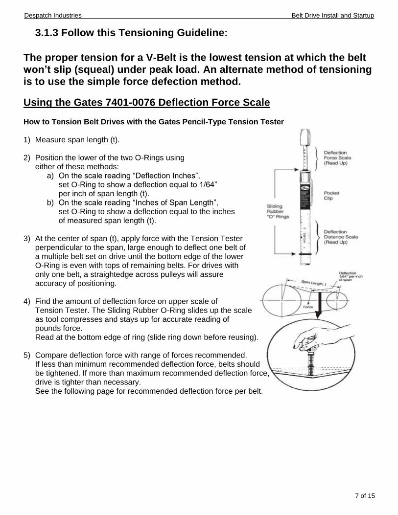
3.1.3 Follow this Tensioning Guideline:
The proper tension for a V-Belt is the lowest tension at which the belt won’t slip (squeal) under peak load. An alternate method of tensioning is to use the simple force defection method.
Using the Gates 7401-0076 Deflection Force Scale How to Tension Belt Drives with the Gates Pencil-Type Tension Tester 1) Measure span length (t).
2) Position the lower of the two O-Rings using
either of these methods: a) On the scale reading “Deflection Inches”,
set O-Ring to show a deflection equal to 1/64” per inch of span length (t).
b) On the scale reading “Inches of Span Length”, set O-Ring to show a deflection equal to the inches of measured span length (t).
3) At the center of span (t), apply force with the Tension Tester perpendicular to the span, large enough to deflect one belt of a multiple belt set on drive until the bottom edge of the lower O-Ring is even with tops of remaining belts. For drives with only one belt, a straightedge across pulleys will assure accuracy of positioning.
4) Find the amount of deflection force on upper scale of Tension Tester. The Sliding Rubber O-Ring slides up the scale as tool compresses and stays up for accurate reading of pounds force. Read at the bottom edge of ring (slide ring down before reusing).
5) Compare deflection force with range of forces recommended. If less than minimum recommended deflection force, belts should be tightened. If more than maximum recommended deflection force, drive is tighter than necessary. See the following page for recommended deflection force per belt.

Despatch Industries Belt Drive Install and Startup
8 of 15
Recommended Deflection Force
Per Belt for Super HC® V-Belts and PowerBands®
V-Belt
Cross
Section
Small
Sheave
Dia. Range (In.)
Small
Sheave
RPM Range
Recommended Defection Force (Lbs.)
Non-Notched Notched
Minimum Maximum Minimum Maximum
3V 3VX
2.2 2.35 to 2.5 2.65 to 2.8 3.00 to 3.15 3.35 to 3.65 4.12 to 5.00 5.30 to 6.90
1200-3600 1200-3600 1200-3600 1200-3600 1200-3600 900-3600 900-3600
- -
3.0 3.3 3.7 4.4 4.8
- -
4.3 4.8 5.4 6.4 7.1
2.8 3.2 3.5 3.8 4.1 4.8 5.8
4.1 4.7 5.1 5.5 6.0 7.1 8.6
5V 5VX
4.4 to 4.65 4.9 to 5.5 5.9 to 6.7
7.10 to 8.00 8.5 to 10.90 11.80 to 16.00
1200-3600 1200-3600 1200-3600 600-1800 600-1800 400-1200
- - -
11.0 13.0 14.0
- - -
16.0 18.0 21.0
9.0 10.0 11.0 13.0 14.0 15.0
13.0 15.0 17.0 19.0 20.0 23.0
8V 8VX
12.50 to 17.00 600-1200 18.00 to 24.00
28.0 400-900
41.0 32.0
- 48.0
- -
Speed Ratio Range: 2.00 to 4.00
Per Belt for Hi Power II® V-Belts and PowerBands®
V-Belt
Cross
Section
Small
Sheave
Dia. Range (In.)
Small
Sheave
RPM Range
Recommended Defection Force (Lbs.)
Hi Power II Non-
Notched
Tri-Power
Notched
Minimum Maximum Minimum Maximum
A AX
3 3.2
3.4 to 3.6 3.8 to 4.2 4.6 to 7.0
1750-3600 2.7 2.9 3.3 3.8 4.9
3.8 4.2 4.8 5.5 7.1
3.8 3.9 4.1 4.3 4.9
5.4 5.6 5.9 6.3 7.1
B BX
4.6 5.0 to 5.2 5.4 to 5.6 6.0 to 6.8 7.4 to 9.4
1160-1800 5.1 5.8 6.2 7.1 8.1
7.4 8.5 9.1 10.0 12.0
7.1 7.3 7.4 7.7 7.9
10.0 11.0 11.0 11.0 12.0
C CX
7 7.5
8.0 to 8.5 9.0 to 10.5
11.00 to 16.00
870-1800 9.1 9.7 11.0 12.0 14.0
13.0 14.0 16.0 18.0 21.0
12.0 12.0 13.0 13.0 13.0
18.0 18.0 18.0 19.0 19.0
D
12.00 to 13.00 13.5 to 15.5
16.00 to 22.00
690-1200 19.0 21.0 24.0
27.0 30.0 36.0
- - -
- - -
Speed Ratio Range: 2.00 to 4.00
* When installing a new belt, always use maximum lbs. as deflection standard ** Deflect belts 1/64 inch per inch of Span

Despatch Industries Belt Drive Install and Startup
9 of 15
6) Recheck sheave alignment.
7) Tighten the motor to base mounting bolts.
8) If possible, run the drive for a few minutes to seat the belts. Otherwise, rotate the drive assembly by hand several revolutions.

Despatch Industries Belt Drive Install and Startup
10 of 15
SECTION 4 – DRIVE SYSTEM STARTUP
4.1 Starting the Drive System
4.1.1 Before starting the drive
Operational Checklist Verify that proper safety precautions have been followed Electrical power and control functionality must be available.
Check fan mechanism components: Nuts, bolts, setscrews are tight. Rotating assembly turns freely prior to connecting any ducting or inlet box Mounting connections are properly made and tightened. Bearings are properly lubricated per manufacturer’s instructions Wheel, drives and fan surfaces are clean and tightened. Rotating assembly turns freely and does not rub. Drives on correct shafts, properly aligned, and properly tensioned.
Check fan electrical components: Motor is wired for proper supply voltage. Motor was properly sized for power of rotating assembly. Motor is properly grounded. All leads are properly insulated.
Trial “bump”: Turn on the motor and allow it to reach full speed before turning off the motor. Check rotation for agreement with rotation arrow. Correct if necessary, the motor rotation as
required to provide the correct rotation of the heater box recirculation fan. Turn on the motor and allow it to reach the set speed. Listen for any unusual noise.
4.1.2 VFD Operation
If the drive system utilizes a VFD to control the motor, verify that the VFD parameters are correct and that the acceleration is set to 60 seconds. The deceleration should be set to 60 seconds as well. The drive should be setup for current limiting operation to prevent the Recirculation fan Motors from exceeding their Full Load Amps Rating.
After 8 hours of motor fan drive operation, shut the drive down and inspect the fan mechanism components:
Verify all nuts, bolts setscrews found on the motor drive and Recirculation Fan assemblies are secure and tighten if necessary.
Measure the belt tension on each drive and record on the form listed on the following page.

Despatch Industries Belt Drive Install and Startup
11 of 15
4.2 Record Installation Final Belt Tension
Type and Product Description of drive belt being used____________________ V-Belt cross section type _______ Motor sheave DIA______ Small Sheave RPM Range_______
Manufacturers Suggested Deflection Maximum Deflection Force = _______ (Lbs.)
Manufacturers Suggested Deflection Minimum Deflection Force = _______ (Lbs.)
Oven 1 Zone 1 Measured Deflection Force =
_______
Oven 1 Zone 2 Measured Deflection Force =
_______
Oven 2 Zone 1 Measured Deflection Force =
_______
Oven 2 Zone 2 Measured Deflection Force =
_______
Oven 3 Zone 1 Measured Deflection Force =
_______
Oven 3 Zone 2 Measured Deflection Force =
_______
Oven 4 Zone 1 Measured Deflection Force =
_______
Oven 4 Zone 2 Measured Deflection Force =
_______
Despatch Industries Belt Drive Install and Startup
12 of 15
SECTION 5 - LUBRICATION
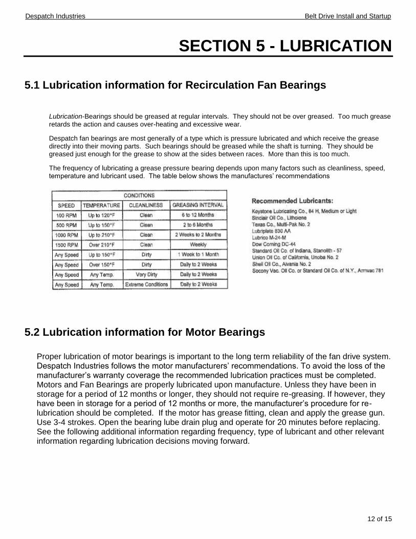
5.1 Lubrication information for Recirculation Fan Bearings
Lubrication-Bearings should be greased at regular intervals. They should not be over greased. Too much grease retards the action and causes over-heating and excessive wear.
Despatch fan bearings are most generally of a type which is pressure lubricated and which receive the grease directly into their moving parts. Such bearings should be greased while the shaft is turning. They should be greased just enough for the grease to show at the sides between races. More than this is too much.
The frequency of lubricating a grease pressure bearing depends upon many factors such as cleanliness, speed, temperature and lubricant used. The table below shows the manufactures’ recommendations
5.2 Lubrication information for Motor Bearings
Proper lubrication of motor bearings is important to the long term reliability of the fan drive system. Despatch Industries follows the motor manufacturers’ recommendations. To avoid the loss of the manufacturer’s warranty coverage the recommended lubrication practices must be completed. Motors and Fan Bearings are properly lubricated upon manufacture. Unless they have been in storage for a period of 12 months or longer, they should not require re-greasing. If however, they have been in storage for a period of 12 months or more, the manufacturer’s procedure for re-lubrication should be completed. If the motor has grease fitting, clean and apply the grease gun. Use 3-4 strokes. Open the bearing lube drain plug and operate for 20 minutes before replacing. See the following additional information regarding frequency, type of lubricant and other relevant information regarding lubrication decisions moving forward.

Despatch Industries Belt Drive Install and Startup
13 of 15

Despatch Industries Belt Drive Install and Startup
14 of 15
SECTION 6 - REFERENCE MATERIAL
6.1 Using Taperlock Hub & Bushing
6.1.1 Installation Instructions
Figure 1. Split Taper Bushing with Hub
a. Belt drive sheaves and occasionally fan impellers are furnished with split taper bushings for mounting to the shaft. When properly assembled, the bushings grip the hub with positive clamping action. b. Cap screws, when tightened, lock the bushing in the impeller. c. The bushing is split so that when the locking cap screws force the bushing into the tapered bore, the bushing grips the shaft with a positive clamping fit. This will withstand vibration and punishing loads without being loosened. d. The bushing assembly is keyed to the shaft and held in place by compression. This gives added driving strength. Before assembly, be sure that the shaft and keyway are clean and smooth. Check the key size with both the shaft and bushing keyways. e. To assemble, insert the cap screws through the clearance holes in the bushing and place the bushing loosely into the impeller. Do not press or drive. Start the cap screws by hand, turning them just enough to engage the threads in the tapped holes on the impeller. Do not use a wrench at this time. The bushing should be loose enough in the impeller to move slightly. Slide the impeller and bushing assembly onto the shaft, making allowance for endplay of the shaft to prevent rubbing. Install the key into the keyway. Do not force the impeller and bushing onto the shaft. If it does not go on easily, check the shaft, bushing and key sizes once again.
Despatch Industries Belt Drive Install and Startup
15 of 15
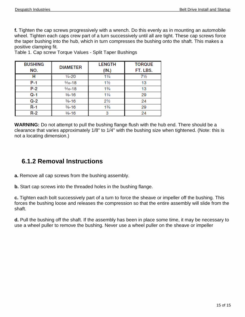
f. Tighten the cap screws progressively with a wrench. Do this evenly as in mounting an automobile wheel. Tighten each caps crew part of a turn successively until all are tight. These cap screws force the taper bushing into the hub, which in turn compresses the bushing onto the shaft. This makes a positive clamping fit. Table 1. Cap screw Torque Values - Split Taper Bushings
WARNING: Do not attempt to pull the bushing flange flush with the hub end. There should be a clearance that varies approximately 1/8" to 1/4" with the bushing size when tightened. (Note: this is not a locating dimension.)
6.1.2 Removal Instructions
a. Remove all cap screws from the bushing assembly. b. Start cap screws into the threaded holes in the bushing flange. c. Tighten each bolt successively part of a turn to force the sheave or impeller off the bushing. This forces the bushing loose and releases the compression so that the entire assembly will slide from the shaft. d. Pull the bushing off the shaft. If the assembly has been in place some time, it may be necessary to use a wheel puller to remove the bushing. Never use a wheel puller on the sheave or impeller


