U.S. Department of Energy • Office of Fossil Energy National Energy Technology Laboratory Carbon Sequestration Technology and Program Plan 2007 Roadmap Ensuring the Future of Fossil Energy Systems through the Successful Deployment of Carbon Capture and Storage Technologies
Transcript
U . S . D e p a r t m e n t o f E n e r g y • O f f i c e o f F o s s i l E n e r g y
N a t i o n a l E n e r g y T e c h n o l o g y L a b o r a t o r y
Carbon SequestrationTechnology
andProgram Plan
2007
Roadmap
Ensuring the Future of Fossil Energy Systems through the Successful Deployment of Carbon Capture and Storage Technologies
IV. Technology Development Efforts __________________________________________ 16 A.CoreR&D.............................................................................16
I. Message to Stakeholders Economic growth is closely tied to energy availability and consumption, particularly lower-cost fossil fuels. The use of these fossil fuels results in the release of carbon dioxide (CO
2), which is widely believed to
contribute to global climate change. Balancing the economic value of fossil fuels with the environmental concerns associated with fossil fuel use is a difficult challenge. To retain fossil fuels as a viable world energy source, carbon capture and storage (CCS) technologies must play a central role. By cost-effectively capturing CO
2 before it is emitted to
the atmosphere and then permanently storing or sequestering it, fossil fuels can be used in a carbon constrained world and without constraining economic growth.
The global nature of CO2 emissions
is illustrated in Figure 1 and shows that total world CO
2 emissions are
expected to increase significantly by 2030. Absent binding constraints, CO
2 emissions in Organization
for Economic Cooperation and Development (OECD) countries—which include the United States, most of Europe, Australia, Korea, New Zealand and Japan—are expected to increase at about 1.1 percent per year through 2030. CO
2 emissions
in non-OECD countries outside Europe and Eurasia—including fossil fuel-rich China and India—are expected to grow at 3.0 percent per year, in line with strong economic growth. As a point of reference, the U.S. emitted about 6 billion metric tons of CO
2 in 2005, accounting for
about 22 percent of total world CO2
emissions.
On a global scale, CCS technologies have the potential to reduce overall climate change mitigation costs and increase flexibility in reducing greenhouse gas (GHG) emissions. According to the 2005 report, Carbon Dioxide Capture and Storage, by the Intergovernmental Panel on Climate Change (IPCC), the application of CCS technologies in GHG mitigation portfolios could reduce the costs of stabilizing CO
2
concentrations in the atmosphere by 30 percent or more compared to scenarios where CCS technologies are not deployed. Furthermore, a particularly beneficial aspect of certain CCS technologies is that their component parts – carbon capture, transportation, and storage – can utilize technologies adapted from other commercial industries, enhancing the availability and cost competitiveness of CCS technologies as viable mitigation options.
The Global Energy Technology Strategy Program (GTSP) – a public and private sector research collaboration comprised of scientists from Battelle, the U.S. Department of Energy (DOE), Pacific Northwest
National Laboratory (PNNL), and the Joint Global Change Research Institute (a partnership between PNNL and the University of Maryland) – has identified near-term, medium-term, and long-term benefits associated with CCS. In the near term, CCS technologies will allow many industries – including electricity generation, refining, chemical production, and steel and cement manufacturing – to chart a viable path forward into a carbon-constrained world. In the medium term, CCS technologies will facilitate a smoother transition of the global economy to a low GHG emissions future. In the long term, CCS will make valuable commodities like electricity and hydrogen cheaper than they would be if such technologies were not available.
DOE is taking a leadership role in the development of CCS technologies. Through its Carbon Sequestration Program (Program) – managed within the Office of Fossil Energy (FE) and implemented by the National Energy Technology Laboratory (NETL) – DOE is
developing both core and supporting technologies through which CCS will become an effective and economically viable option for reducing CO
2 emissions. The
Program works in concert with other programs within FE that are developing technologies integral to coal-fueled power generation with carbon capture: advanced integrated gasification combined cycle (IGCC), advanced turbines, fuel cells, and advanced research. Successful research and development (R&D) will enable carbon control technologies to overcome the various technical, economic, and social challenges, including cost-effective CO
2 capture, long-term
stability (permanence) of CO2 in
underground formations, monitoring and verification, integration with power generation systems, and public acceptance.
The overall goal of the Carbon Sequestration Program is to develop, by 2012, fossil fuel conversion systems that achieve 90 percent CO
2 capture with 99 percent storage
permanence at less than a 10 percent increase in the cost of energy services. Reaching this goal requires an integrated research, development, and deployment program linking fundamental advances in CCS to practical advances in technologies amenable to extended commercial use. The technologies developed in this Program will also serve as test components in the FutureGen Initiative, aimed at building the first power plant in the world to integrate permanent carbon storage with coal-to-energy conversion and hydrogen production.
A.10-yearMilestonefortheDOECarbonSequestrationProgramThe year 2007 marks the 10-year anniversary of the DOE’s Carbon Sequestration Program. Launched in 1997 as a small-scale research effort to ascertain the technical viability of CCS, the Program has grown into a multi-faceted research, development, and deployment initiative that aims to provide the means by which fossil fuels can continue to be used for power generation in a carbon-constrained world. The first 10 years have significantly advanced the knowledge base pertaining to CO
2
separation, geologic and terrestrial storage, regulations and permitting, and process economics. Much work remains, however, to enable the large-scale deployment of CCS technologies. In particular, extended field tests are required to fully characterize potential storage sites and demonstrate the long-term storage of sequestered carbon to achieve cost-effective integration with power plant systems. Looking forward, it is also important to recognize CCS as more than just an end-of-process emissions control technology. CCS technologies represent critical elements in the entire energy supply picture, providing CO
2 capture and storage
solutions that will enable sustained fossil fuel conversion and offer a resource recovery pathway that will facilitate greater recovery of domestic oil, natural gas, and coalbed methane.
This document describes the Technology Roadmap and Program Plan that will guide the Carbon Sequestration Program in 2007 and beyond. An overview of the Program and the key accomplishments in its 10-year history are presented as well as the challenges confronting deployment and successful commercialization of carbon sequestration technologies. The research pathways that will be used to achieve Program goals and information on key contacts and web links related to the Program are included.
This document is intended to be a valuable tool in engaging interested stakeholders. We invite readers to contact any of the persons listed on the inside back cover with comments, concerns, or suggestions.
II. Program OverviewThe DOE’s Carbon Sequestration Program leverages applied research with field demonstrations to assess the technical and economic viability of carbon capture and storage as a GHG mitigation option.
A.ProgramHighlightsandAccomplishmentsSince its inception 10 years ago, the Program has been moving CCS technology forward to enable its cost-effective use in meeting any future GHG emissions reduction requirements. The first decade has significantly advanced the knowledge base pertaining to CO
2 separation,
geologic and terrestrial sequestration, regulations and permitting, and process economics.
The Program is a true government success story. What began as an idea has resulted in international support of CCS as a leading mitigation option for reducing GHG emissions to the atmosphere. Major Program accomplishments over its 10-year life include:
• Carbon Sequestration Atlas. The Carbon Sequestration Atlas of the United States and Canada – developed by NETL, the Regional Carbon Sequestration Partnerships (RCSPs), and the National Carbon Sequestration Database and Geographical Information System (NATCARB) – contains information on stationary sources for CO
2
emissions, geologic formations
with sequestration potential, and terrestrial ecosystems with potential for enhanced carbon uptake, all referenced to their geographic location to enable matching sources and sequestration sites. An interactive version of the Atlas is available through the NATCARB website (www.natcarb.org). The Atlas can be downloaded at http://www.netl.doe.gov/publications/carbon_seq/atlas/index.html.
• CO2 Capture. The Program has
conducted research into solvent, sorbent, membrane, and oxy-combustion systems that, upon successful development, will be capable of capturing greater than 90 percent of the flue gas CO
2
at a significant cost reduction when compared to state-of-the-art, amine-based capture systems. Through research and systems analysis over the past years, potential cost reductions of 30-45 percent have been identified for the capture of CO
2. In addition, ionic liquid
membranes and absorbents are being developed for capture of CO
2 from power plants. Ionic
liquid membranes have been developed at NETL for pre-combustion applications that surpass polymers in terms of CO
2
selectivity and permeability at elevated temperatures. In related DOE-funded academic research, significant progress has been made in developing ionic liquid absorbents for post-combustion applications that show increasing breakthrough potential for more cost effective capture of CO
2 from
flue gas.
• CO2 Storage. Program efforts
in geologic and terrestrial CO2
storage have led to a better understanding of sequestration potential and the ability to characterize capillary forces that immobilize CO
2 in the pore
spaces of a formation – also known as residual CO
2 trapping –
in CO2 fate and transport models.
Furthermore, the Program has been a leader in efforts to enhance terrestrial ecosystems as carbon sequestration sites and to calibrate models for quantifying the amount of carbon stored.
• Monitoring, Mitigation, and Verification (MM&V). Field projects have demonstrated the ability to “map” CO
2 injected
into an underground formation at a much higher resolution than previously anticipated and confirmed the ability of perfluorocarbon tracers to track CO
2 movement through
a reservoir. DOE-sponsored research has also led to the development of the U-Tube sampler, which was developed for and successfully deployed at the Frio test site in Texas. This novel tool is used to obtain geochemical samples of both the water and gas portions of downhole samples at in situ pressure. The data collected from this tool has led to a better understanding of the coupled hydrogeochemical conditions affecting CO
2 storage
in brine filled formations.
• Systems Analysis. NETL’s Office of Systems, Analysis, and Planning (OSAP) has conducted innovative assessments of CO
2
capture and separations processes. The OSAP work in this area has increased understanding of the
fuel conversion systems, leading to the identification of improvement opportunities with the potential to significantly reduce costs. Two recently completed systems analyses are documented in the following reports: CO
2 Capture
from Existing Coal-Fired Power Plants and Cost and Performance Baseline for Fossil Energy Plants. (Reports at: http://www.netl.doe.gov/technologies/carbon_seq/Resources/Analysis/)
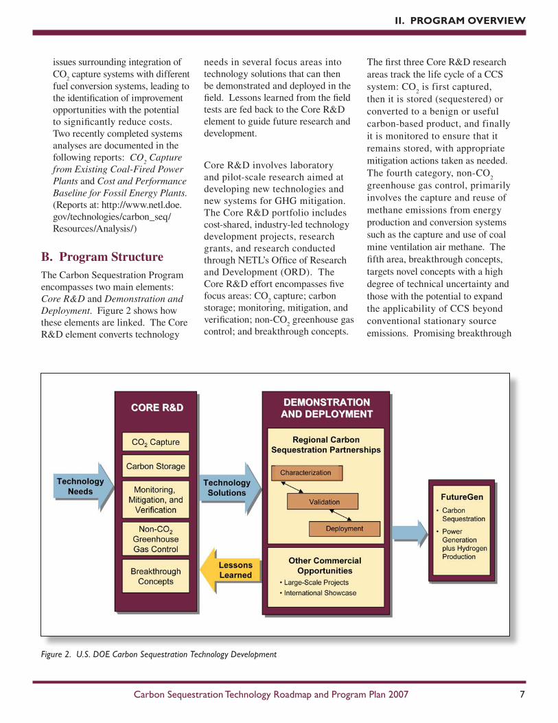
B.ProgramStructureThe Carbon Sequestration Program encompasses two main elements: Core R&D and Demonstration and Deployment. Figure 2 shows how these elements are linked. The Core R&D element converts technology
needs in several focus areas into technology solutions that can then be demonstrated and deployed in the field. Lessons learned from the field tests are fed back to the Core R&D element to guide future research and development.
Core R&D involves laboratory and pilot-scale research aimed at developing new technologies and new systems for GHG mitigation. The Core R&D portfolio includes cost-shared, industry-led technology development projects, research grants, and research conducted through NETL’s Office of Research and Development (ORD). The Core R&D effort encompasses five focus areas: CO
2 capture; carbon
storage; monitoring, mitigation, and verification; non-CO
2 greenhouse gas
control; and breakthrough concepts.
The first three Core R&D research areas track the life cycle of a CCS system: CO
2 is first captured,
then it is stored (sequestered) or converted to a benign or useful carbon-based product, and finally it is monitored to ensure that it remains stored, with appropriate mitigation actions taken as needed. The fourth category, non-CO
2
greenhouse gas control, primarily involves the capture and reuse of methane emissions from energy production and conversion systems such as the capture and use of coal mine ventilation air methane. The fifth area, breakthrough concepts, targets novel concepts with a high degree of technical uncertainty and those with the potential to expand the applicability of CCS beyond conventional stationary source emissions. Promising breakthrough
II. PROGRAM OVERVIEw
Figure 2. U.S. DOE Carbon Sequestration Technology Development
Figure 3. Energy Recovery and Conversion Relationships
concepts being pursued include ionic liquids and microporous metal organic frameworks (MOFs) for capturing CO
2.
The Demonstration and Deployment element of the Carbon Sequestration Program is designed to demonstrate the viability of CCS technologies at a scale large enough to overcome real and perceived infrastructure challenges. Technologies will be tested in the field to identify and eliminate technical and economic barriers to commercialization. Such an effort is necessary to ensure that organizations are prepared to act if future global climate change policies require large-scale deployment of sequestration technology.
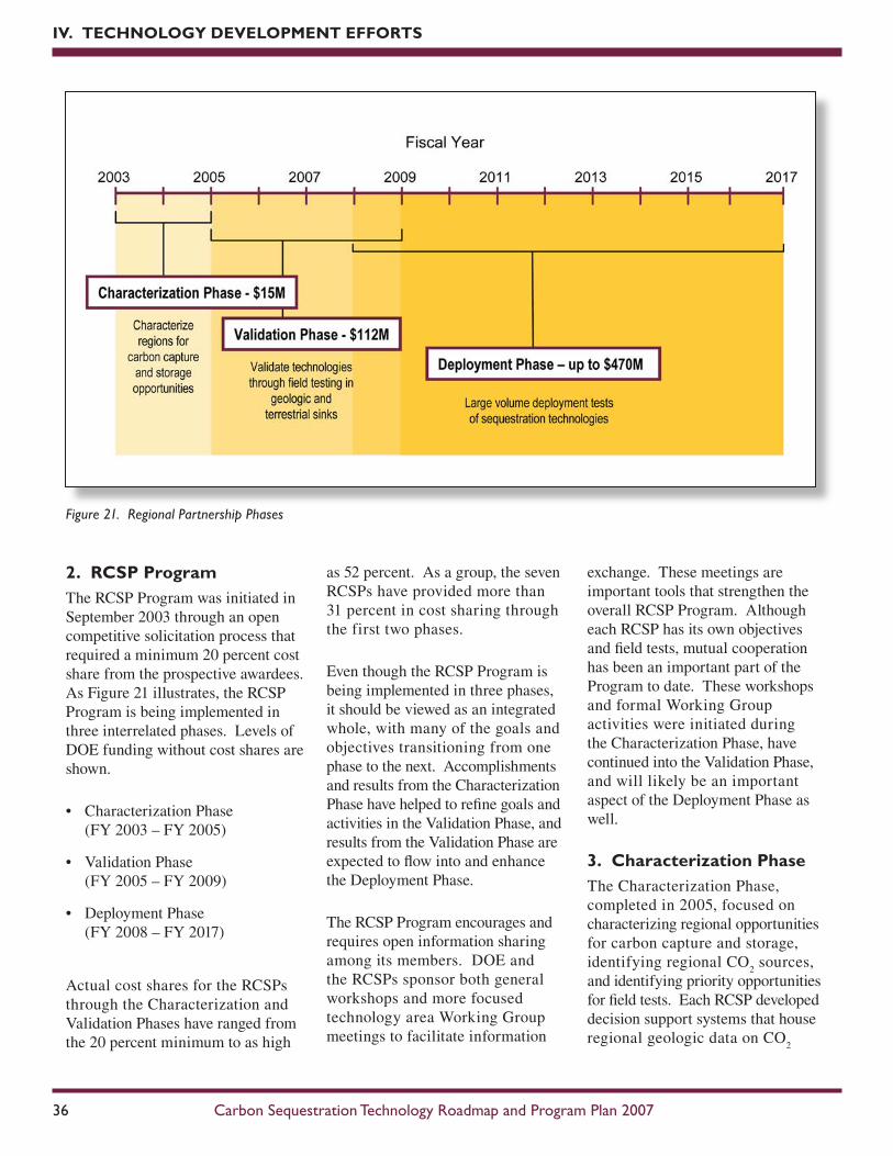
The largest component of the Demonstration and Deployment element is the Regional Carbon Sequestration Partnerships Program. The seven RCSPs are examining regional differences in geology, land practices, ecosystem management, and industrial activity that can affect the deployment of CCS technologies. The Carbon Sequestration Program also supports FutureGen, a key DOE initiative aimed at building a highly efficient and technologically sophisticated power plant that can produce both hydrogen and electricity while capturing and sequestering CO
2 emissions.
FutureGen will serve as a full-scale field laboratory for CCS technologies, providing a venue for evaluating technologies emerging from Core R&D efforts.
The Carbon Sequestration Program consists of supporting mechanisms performing systems analyses and
economic modeling of potential new CO
2 capture processes to identify
issues with their integration into full-scale power plants. The Program also participates in cross-cutting studies to model future national energy scenarios incorporating carbon sequestration. Finally, the Program collaborates with other U.S. government agencies with overlapping responsibilities and works with the international community through its membership in organizations such as the Carbon Sequestration Leadership Forum (CSLF).
C.ProgramRoleFigure 3 illustrates the unique role that CCS could play in future energy supply networks. The long-term viability of various fuel conversion pathways – including pulverized coal (PC) combustion, integrated gasification combined-cycle, biomass gasification, and coal-to-liquids – may hinge on the availability of
cost-effective CCS technologies. However, carbon capture and subsurface injection represents more than just an end-of-process emissions control technology. These technologies could provide additional value by facilitating the recovery of several subsurface resources, including oil, natural gas, and coalbed methane.
Currently, in the absence of regulations limiting or taxing carbon emissions, the private sector has little incentive to develop and deploy commercial CCS technologies. However, through cost-shared R&D, the Federal government has a role to play in ensuring the availability of cost-effective technologies for capturing and sequestering CO
2 from fossil
fuel use. Commercial availability of CCS technology provides public benefits in the form of the continued use of cost-effective fossil fuels in an environmentally friendly manner.
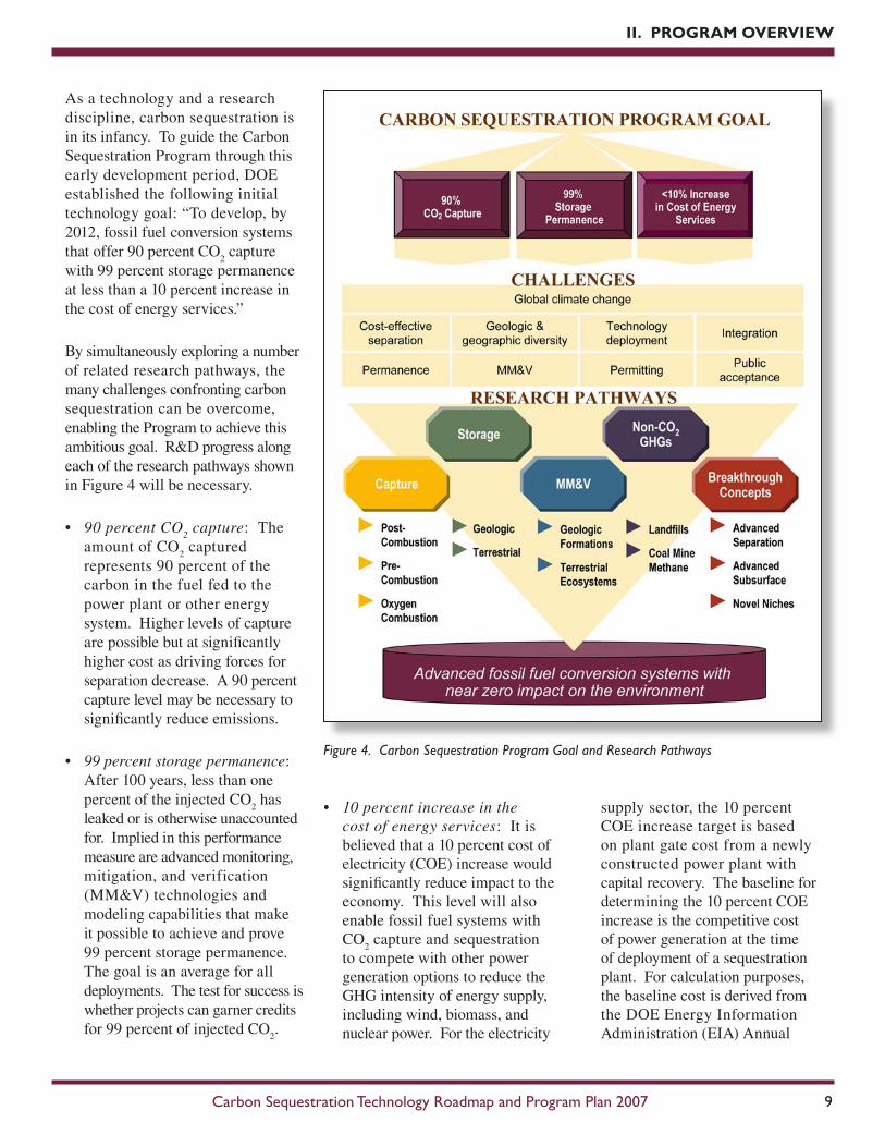
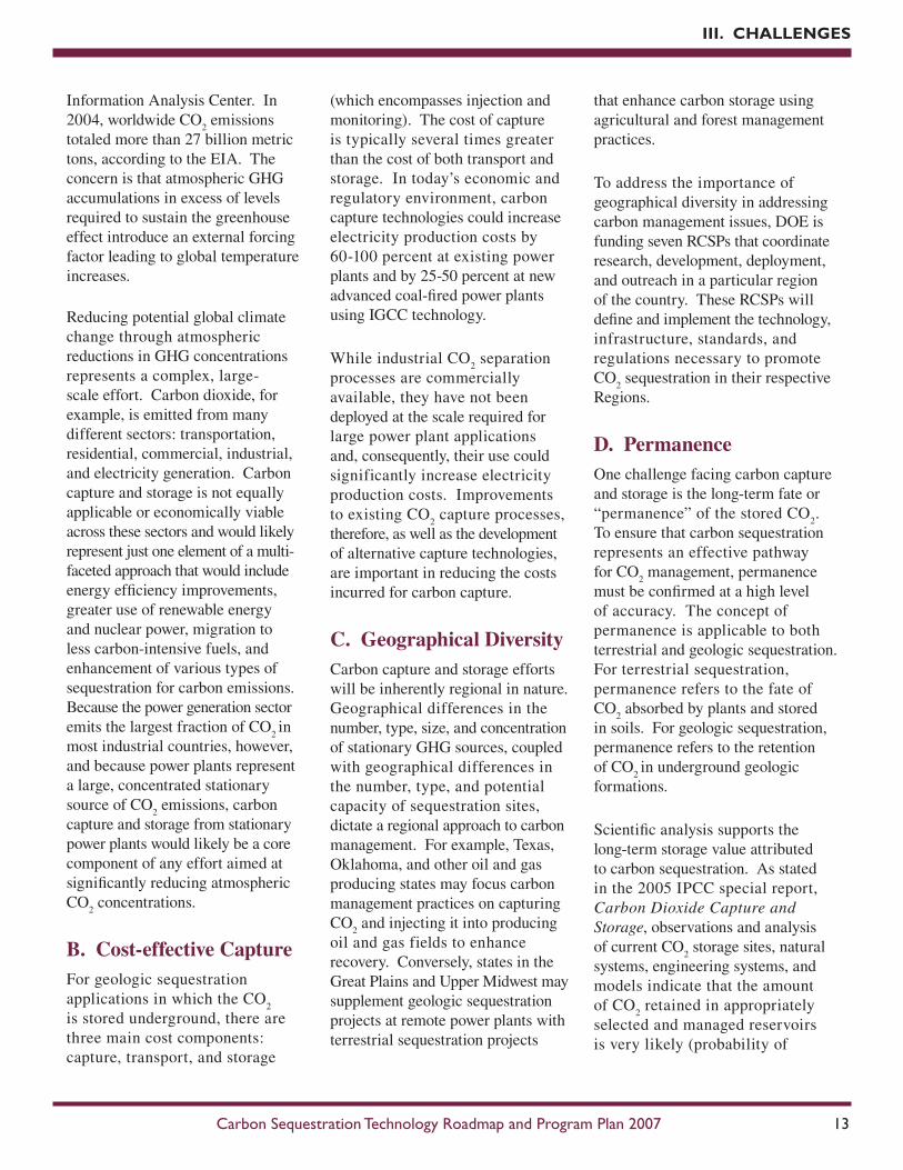
As a technology and a research discipline, carbon sequestration is in its infancy. To guide the Carbon Sequestration Program through this early development period, DOE established the following initial technology goal: “To develop, by 2012, fossil fuel conversion systems that offer 90 percent CO
2 capture
with 99 percent storage permanence at less than a 10 percent increase in the cost of energy services.”
By simultaneously exploring a number of related research pathways, the many challenges confronting carbon sequestration can be overcome, enabling the Program to achieve this ambitious goal. R&D progress along each of the research pathways shown in Figure 4 will be necessary.
• 90 percent CO2 capture: The
amount of CO2 captured
represents 90 percent of the carbon in the fuel fed to the power plant or other energy system. Higher levels of capture are possible but at significantly higher cost as driving forces for separation decrease. A 90 percent capture level may be necessary to significantly reduce emissions.
• 99 percent storage permanence: After 100 years, less than one percent of the injected CO
2 has
leaked or is otherwise unaccounted for. Implied in this performance measure are advanced monitoring, mitigation, and verification (MM&V) technologies and modeling capabilities that make it possible to achieve and prove 99 percent storage permanence. The goal is an average for all deployments. The test for success is whether projects can garner credits for 99 percent of injected CO
2.
• 10 percent increase in the cost of energy services: It is believed that a 10 percent cost of electricity (COE) increase would significantly reduce impact to the economy. This level will also enable fossil fuel systems with CO
2 capture and sequestration
to compete with other power generation options to reduce the GHG intensity of energy supply, including wind, biomass, and nuclear power. For the electricity
supply sector, the 10 percent COE increase target is based on plant gate cost from a newly constructed power plant with capital recovery. The baseline for determining the 10 percent COE increase is the competitive cost of power generation at the time of deployment of a sequestration plant. For calculation purposes, the baseline cost is derived from the DOE Energy Information Administration (EIA) Annual
Figure 4. Carbon Sequestration Program Goal and Research Pathways
Energy Outlook projection for the average generation cost of electricity from the utility sector. The cost of CO
2 capture and
storage includes parasitic power requirements, CO
2 compression,
pipeline transport of 50 miles, and injection into a saline formation. Revenues from CO
2 sales for
enhanced oil recovery (EOR), enhanced gas recovery (EGR), and enhanced coalbed methane (ECBM) recovery are not credited against the cost of CO
2 capture.
Net reductions in the cost of criteria pollutant control are included.
• By 2012: The Program seeks to have pilot-scale unit operation performance results from a combination of CO
2 capture,
MM&V, and storage system components such that, when integrated into a systems analysis framework, would collectively
meet the above goals. Accounting for the lag associated with pre-large-scale validation and design and construction of large-scale systems, projects that meet the Program goal will result in large-scale units that come on-line around 2020.
For an evolving technology Program such as carbon sequestration, this initial Program goal represents a near-term opportunity to gauge Program progress and success. Longer-term goals are important to further explore the capabilities and potential of carbon sequestration. Figure 5 summarizes important accomplishments in the Program history and also lists future Program milestones. Additional milestones will be added as lessons learned from the Demonstration and Deployment element are fed back to the Core R&D element to guide future efforts.
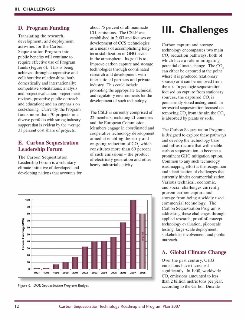
D.ProgramFundingTranslating the research, development, and deployment activities for the Carbon Sequestration Program into public benefits will continue to require effective use of Program funds (Figure 6). This is being achieved through cooperative and collaborative relationships, both domestically and internationally: competitive solicitations; analysis and project evaluation; project merit reviews; proactive public outreach and education; and an emphasis on cost-sharing. Currently, the Program funds more than 70 projects in a diverse portfolio with strong industry support that is evident by the average 31 percent cost share of projects.
E.CarbonSequestrationLeadershipForumThe Carbon Sequestration Leadership Forum is a voluntary climate initiative of developed and developing nations that accounts for
about 75 percent of all manmade CO
2 emissions. The CSLF was
established in 2003 and focuses on development of CCS technologies as a means of accomplishing long-term stabilization of GHG levels in the atmosphere. Its goal is to improve carbon capture and storage technologies through coordinated research and development with international partners and private industry. This could include promoting the appropriate technical, and regulatory environments for the development of such technology.
The CSLF is currently comprised of 22 members, including 21 countries and the European Commission. Members engage in coordinated and cooperative technology development aimed at enabling the early and on-going reduction of CO
2 which
constitutes more than 60 percent of such emissions – the product of electricity generation and other heavy industrial activity.
III. ChallengesCarbon capture and storage technology encompasses two main CO
2 reduction pathways, both of
which have a role in mitigating potential climate change. The CO
2
can either be captured at the point where it is produced (stationary source) or it can be removed from the air. In geologic sequestration focused on capture from stationary sources, the captured CO
2 is
permanently stored underground. In terrestrial sequestration focused on removing CO
2 from the air, the CO
2
is absorbed by plants or soils.
The Carbon Sequestration Program is designed to explore these pathways and develop the technology base and infrastructure that will enable carbon sequestration to become a prominent GHG mitigation option. Common to any such technology roadmapping effort is the recognition and identification of challenges that currently hinder commercialization. Various technical, economic, and social challenges currently prevent carbon capture and storage from being a widely used commercial technology. The Carbon Sequestration Program is addressing these challenges through applied research, proof-of-concept technology evaluation, pilot-scale testing, large-scale deployment, stakeholder involvement, and public outreach.
A.GlobalClimateChangeOver the past century, GHG emissions have increased significantly. In 1900, worldwide CO
2 emissions amounted to less
than 2 billion metric tons per year, according to the Carbon Dioxide Figure 6. DOE Sequestration Program Budget
Information Analysis Center. In 2004, worldwide CO
2 emissions
totaled more than 27 billion metric tons, according to the EIA. The concern is that atmospheric GHG accumulations in excess of levels required to sustain the greenhouse effect introduce an external forcing factor leading to global temperature increases. Reducing potential global climate change through atmospheric reductions in GHG concentrations represents a complex, large-scale effort. Carbon dioxide, for example, is emitted from many different sectors: transportation, residential, commercial, industrial, and electricity generation. Carbon capture and storage is not equally applicable or economically viable across these sectors and would likely represent just one element of a multi-faceted approach that would include energy efficiency improvements, greater use of renewable energy and nuclear power, migration to less carbon-intensive fuels, and enhancement of various types of sequestration for carbon emissions. Because the power generation sector emits the largest fraction of CO
2 in
most industrial countries, however, and because power plants represent a large, concentrated stationary source of CO
2 emissions, carbon
capture and storage from stationary power plants would likely be a core component of any effort aimed at significantly reducing atmospheric CO
2 concentrations.
B.Cost-effectiveCaptureFor geologic sequestration applications in which the CO
2
is stored underground, there are three main cost components: capture, transport, and storage
(which encompasses injection and monitoring). The cost of capture is typically several times greater than the cost of both transport and storage. In today’s economic and regulatory environment, carbon capture technologies could increase electricity production costs by 60-100 percent at existing power plants and by 25-50 percent at new advanced coal-fired power plants using IGCC technology.
While industrial CO2 separation
processes are commercially available, they have not been deployed at the scale required for large power plant applications and, consequently, their use could significantly increase electricity production costs. Improvements to existing CO
2 capture processes,
therefore, as well as the development of alternative capture technologies, are important in reducing the costs incurred for carbon capture.
C.GeographicalDiversityCarbon capture and storage efforts will be inherently regional in nature. Geographical differences in the number, type, size, and concentration of stationary GHG sources, coupled with geographical differences in the number, type, and potential capacity of sequestration sites, dictate a regional approach to carbon management. For example, Texas, Oklahoma, and other oil and gas producing states may focus carbon management practices on capturing CO
2 and injecting it into producing
oil and gas fields to enhance recovery. Conversely, states in the Great Plains and Upper Midwest may supplement geologic sequestration projects at remote power plants with terrestrial sequestration projects
that enhance carbon storage using agricultural and forest management practices.
To address the importance of geographical diversity in addressing carbon management issues, DOE is funding seven RCSPs that coordinate research, development, deployment, and outreach in a particular region of the country. These RCSPs will define and implement the technology, infrastructure, standards, and regulations necessary to promote CO
2 sequestration in their respective
Regions.
D.PermanenceOne challenge facing carbon capture and storage is the long-term fate or “permanence” of the stored CO
2.
To ensure that carbon sequestration represents an effective pathway for CO
2 management, permanence
must be confirmed at a high level of accuracy. The concept of permanence is applicable to both terrestrial and geologic sequestration. For terrestrial sequestration, permanence refers to the fate of CO
2 absorbed by plants and stored
in soils. For geologic sequestration, permanence refers to the retention of CO
2 in underground geologic
formations.
Scientific analysis supports the long-term storage value attributed to carbon sequestration. As stated in the 2005 IPCC special report, Carbon Dioxide Capture and Storage,observations and analysis of current CO
2 storage sites, natural
systems, engineering systems, and models indicate that the amount of CO
2 retained in appropriately
selected and managed reservoirs is very likely (probability of
90-99 percent) to exceed 99 percent over 100 years and is likely (probability of 66-90 percent) to exceed 99 percent over 1,000 years. Moreover, the potential for leakage is expected to decrease over time as other mechanisms provide additional trapping.
E.Monitoring,Mitigation,andVerificationClosely related to permanence is the issue of monitoring, mitigation, and verification. The ultimate success of carbon capture and storage projects will hinge on the ability to measure the amount of CO
2 stored at a
particular site, the ability to confirm that the stored CO
2 is not harming
the host ecosystem, and the ability to effectively mitigate any impacts associated with a CO
2 leakage.
As with permanence, MM&V is applicable to both terrestrial and geologic sequestration. Terrestrial MM&V must overcome difficulties in assessing carbon storage in large ecosystems (such as forests) and in gauging carbon storage potential in various types of soils. Geologic MM&V must contend with challenges spanning the movement of CO
2 in geologic reservoirs,
the effect of various physical and chemical forces on the CO
2 plume,
leak detection, and the development of robust mitigation techniques that can respond to a variety of potential leakage events.
F.IntegrationandLong-termPerformanceA number of the technological elements associated with carbon capture and storage are proven, but there has been no demonstrated long-term performance at large
industrial sites integrating carbon capture, transportation, and final storage. Much of the knowledge base pertaining to carbon capture and storage has been derived from the oil and natural gas industries, where CO
2 has been injected for
over 30 years for oil recovery and the incremental storage cost is small. Broader implementation is required, particularly in the power generation industry, but such commercialization is not likely absent emission regulations, incentives, or government funding.
Long-term integrated testing and validation is necessary for technical, economic, and regulatory reasons. From a technical perspective, the ability to separate a CO
2 stream
from the power plant flue gas stream, compress it for pipeline delivery, and sustain delivery at pressures adequate to ensure dependable injectivity and reservoir permeability must be confirmed. From an economic perspective, the costs associated with CCS must be quantified in greater detail to encourage investment and ensure cost recovery. From a regulatory perspective, long-term operating data must be collected to ensure that CO
2 transportation
systems, injection wells, and storage reservoirs are properly regulated to safeguard the environment and public health.
G.PermittingandLiabilityBecause carbon capture and storage remains a relatively young technology – particularly in terms of projects in the field – a number of permitting and liability issues are still evolving. With respect to permitting, CO
2 injection and
monitoring wells will have to comply with state and Federal
regulations. In early 2006, the U.S. Environmental Protection Agency (EPA) concluded that geologic sequestration of CO
2 through well
injection met the definition of “underground injection” in the Safe Drinking Water Act. As a result, underground sources of drinking water must be protected from potential endangerment attributed to carbon sequestration pilot projects, most likely through the issuance of underground injection control permits. Currently, injection wells for carbon sequestration with EOR or EGR are being permitted as Class II injection wells (wells that inject waste fluids associated with the production of oil and natural gas). However, injection wells for all other carbon sequestration projects are being permitted as Class V experimental technology wells (wells that are not included in any other class and inject non-hazardous fluids). To ensure that Agency efforts are coordinated and communicated effectively, DOE participates in quarterly meetings at a high management level with EPA. In addition, both DOE and the RCSPs were involved with providing comments for EPA’s first Underground Injection Control program guidance related to permitting initial pilot projects as experimental technology wells, giving regulatory agencies enhanced flexibility in expediting these projects.
Access and liability issues represent another uncertain, evolving challenge. In many states, land rights are held separate from mineral rights, potentially complicating sequestration projects aimed at secondary resource recovery. Gaining access to attractive underground storage sites may prove to be difficult in some cases.
Liability concerns primarily center on which entity or group of entities will be responsible for the CO
2
stored underground after injection is completed. Since the stored CO
2
will conceivably remain underground indefinitely, lines of responsibility must be defined that can track potential damage or impacts to a particular leak. Federal and state agencies, insurance companies, the CO
2 producer, the sequestration site
operator, and the landowner may all be involved in determining the chain of custody, developing appropriate bonding mechanisms, remediating any problems, and providing long-term monitoring. Illinois and Texas have recently addressed these liability issues as they relate to clean coal projects. Legislation pending in Illinois would provide adequate liability protection and permitting certainty to facilitate the siting of a FutureGen project in the state. While the FutureGen plant operator would retain title to and any liabilities associated with the pre-injection CO
2, the state would accept
title to and any liabilities associated with the sequestered gas. Legislation enacted in Texas specifies that the owner or operator of a clean coal project will retain liability for the CO
2 generated before it is captured
but indicates that the state will accept title to the CO
2 captured by
the power plant and may make it available for sale or for injection into a geologic formation for permanent storage.
H.PublicAcceptanceThe public is generally unfamiliar with CCS and the large role it might play in the reduction of GHG emissions. Education and outreach efforts are required to dispel misconceptions, outline
opportunities and challenges, and invite feedback pertaining to implementation mechanisms.
Public support is critical to the success of research and commercialization efforts; more importantly, public disapproval is very difficult to overcome. It is imperative, therefore, that the relevant government and private entities engage the public to explain the technology and address environmental, health, and safety concerns as they arise. Public outreach activities conducted by the RCSP coordinators have included: development and utilization of a suite of educational and outreach tools to communicate with national, regional, and local audiences, policymakers, and stakeholders on the subject of carbon sequestration including a carbon sequestration video for general and non-technical audiences; focus groups to gauge public knowledge and perceptions of carbon sequestration; town hall-style meetings to inform and educate about sequestration; risk communication workshops; and hundreds of carbon sequestration posters, presentations, and other outreach materials for public dissemination.
I.InfrastructureIf carbon capture and storage is widely deployed to control CO
2 emissions, significant
infrastructure investments will be required, particularly for geologic sequestration. Stationary source CO
2 emitters like coal-fired power
plants may have to invest in a host of non-core assets, including carbon separation systems, CO
2 pipelines,
drilling rigs, injection systems, and monitoring networks. Beyond the
capital investment required, emitters may face resource competition for the equipment and personnel needed to install, operate, and maintain these systems. Access to drilling rigs, for example, could become a key issue if the oil and natural gas sectors continue aggressive domestic drilling campaigns.
During the large-scale carbon sequestration test projects planned for the next 10 years, an additional infrastructure challenge involves the supply of sufficient CO
2 to
enable long-term deployment and evaluation. While huge quantities of CO
2 are theoretically available from
power plant sources, separation and supply of this CO
2 for the carbon
storage deployments projects is unlikely because of the expense involved in separating the CO
2
in the absence of CO2 emission
regulations and/or because of the uncertain reliability associated with utility-scale CO
2 separation systems.
In most cases, the CO2 required
for the deployment projects will be supplied from natural sources or from industrial processes that produce a relatively pure CO
2 stream
as a by-product. Securing sufficient quantities of CO
IV. Technology Development EffortsThe Carbon Sequestration Program is developing a portfolio of technologies with great potential to reduce GHG emissions. The primary concentration of this high priority Program is on dramatically lowering the cost and energy requirements of pre- and post-combustion CO
2
capture. The goal is to have a technology portfolio by 2012 for safe, cost-effective, and long-term carbon mitigation, management, and storage, which will lead to substantial market penetration after 2012. In the long-term, the Program is expected to contribute significantly to the President’s goal of developing technologies to substantially reduce GHG emissions.
A.CoreR&DThe Program’s Core R&D element encompasses five focus areas: CO
2 Capture; Carbon Storage;
Monitoring, Mitigation, and Verification; Non-CO
2 Greenhouse
Gas Control; and Breakthrough Concepts. Research activities are conducted through an array of internal and external funding mechanisms, spanning laboratory-scale research through pilot-scale deployment. Focus area research converts technology needs related to CCS into technology solutions ready for larger-scale testing and deployment.
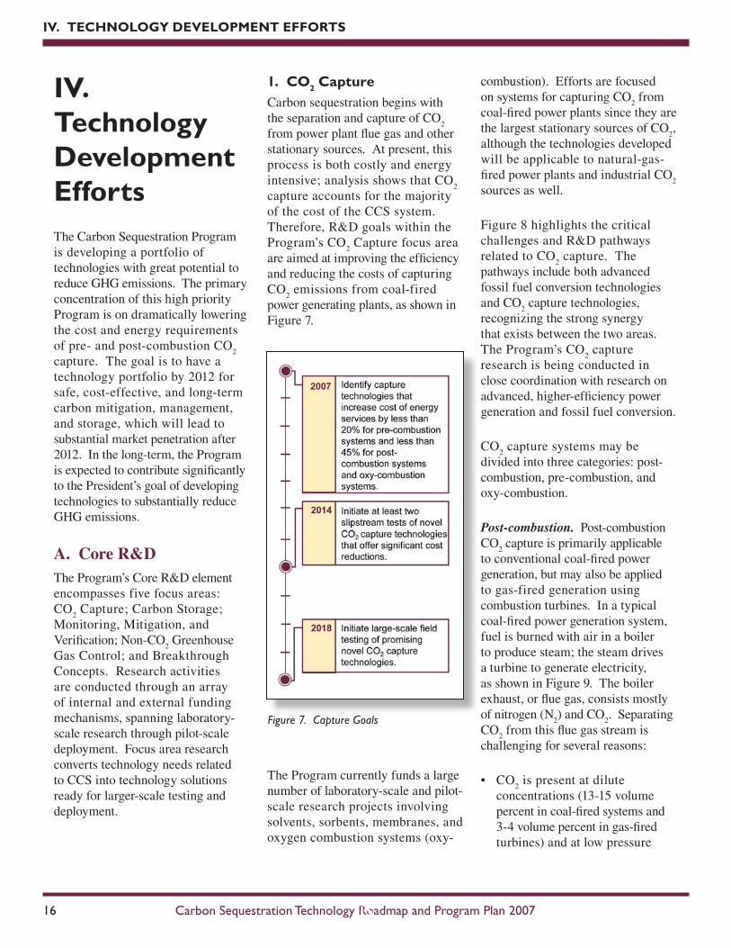
1. CO2 CaptureCarbon sequestration begins with the separation and capture of CO
2
from power plant flue gas and other stationary sources. At present, this process is both costly and energy intensive; analysis shows that CO
2
capture accounts for the majority of the cost of the CCS system. Therefore, R&D goals within the Program’s CO
2 Capture focus area
are aimed at improving the efficiency and reducing the costs of capturing CO
2 emissions from coal-fired
power generating plants, as shown in Figure 7.
The Program currently funds a large number of laboratory-scale and pilot-scale research projects involving solvents, sorbents, membranes, and oxygen combustion systems (oxy-
combustion). Efforts are focused on systems for capturing CO
2 from
coal-fired power plants since they are the largest stationary sources of CO
2,
although the technologies developed will be applicable to natural-gas-fired power plants and industrial CO
2
sources as well.
Figure 8 highlights the critical challenges and R&D pathways related to CO
2 capture. The
pathways include both advanced fossil fuel conversion technologies and CO
2 capture technologies,
recognizing the strong synergy that exists between the two areas. The Program’s CO
2 capture
research is being conducted in close coordination with research on advanced, higher-efficiency power generation and fossil fuel conversion.
CO2 capture systems may be
divided into three categories: post-combustion, pre-combustion, and oxy-combustion.
Post-combustion.Post-combustion CO
2 capture is primarily applicable
to conventional coal-fired power generation, but may also be applied to gas-fired generation using combustion turbines. In a typical coal-fired power generation system, fuel is burned with air in a boiler to produce steam; the steam drives a turbine to generate electricity, as shown in Figure 9. The boiler exhaust, or flue gas, consists mostly of nitrogen (N
2) and CO
2. Separating
CO2 from this flue gas stream is
challenging for several reasons:
• CO2 is present at dilute
concentrations (13-15 volume percent in coal-fired systems and 3-4 volume percent in gas-fired turbines) and at low pressure
(15-25 pounds per square inch absolute [psia]), which dictates that a high volume of gas be treated.
• Trace impurities (particulate matter, sulfur dioxide, nitrogen oxides) in the flue gas can degrade sorbents and reduce the effectiveness of certain CO
2
capture processes.
• Compressing captured or separated CO
2 from atmospheric
pressure to pipeline pressure (about 2,000 psia) represents a large auxiliary power load on the overall power plant system.
Absorption processes based on chemical solvents such as amines, as described in Figure 9, have
been developed and deployed commercially in certain industries. To date, however, their use in PC power plants has been restricted to slipstream applications, and no definitive analysis exists as to the actual costs for a full-scale capture plant. Preliminary analysis conducted at NETL indicates that CO
and compression to 2,200 psia could raise the cost of electricity from a new supercritical PC power plant by 65 percent, from 5.0 cents/kilowatt-hour (kWh) to 8.25 cents/kWh. Pre-combustion.Pre-combustion CO
2 capture relates to gasification
plants, where fuel is converted into gaseous components by applying heat under pressure in the presence of steam (Figure 10). In a gasification reactor, the amount of air or oxygen (O
2) available inside
the gasifier is carefully controlled so that only a portion of the fuel burns completely. This “partial oxidation” process provides the heat necessary to chemically decompose the fuel and produce synthesis gas (syngas), which is composed of hydrogen (H
2), carbon monoxide (CO) and
minor amounts of other gaseous constituents. The syngas is then processed in a water-gas-shift (WGS) reactor, which converts the CO to CO
2 and increases the CO
2 and H
2
mole concentrations to 40 percent and 55 percent, respectively, in the syngas stream.
At this point, the CO2 has a high
partial pressure (and high chemical potential), which improves the driving force for various types of separation and capture technologies. After CO
2
removal, the H2 rich syngas can be
converted to electrical or thermal power. One application is to use H
2
as a fuel in a combustion turbine to generate electricity. Additional electricity is generated by extracting the energy from the combustion turbine flue gas via a heat recovery steam generator. Another application, currently being developed under the DOE Fuel Cell Program, is to utilize the H
2 to power fuel cells with the
intent of significantly raising overall plant efficiency. Because CO
2 is
present at much higher concentrations in syngas than in post-combustion flue gas, CO
2 capture should be
less expensive for pre-combustion capture than for post-combustion capture. Currently, however, there are few gasification plants in full-scale operation and capital costs are higher than for PC plants.
Figure 8 shows the research pathways being pursued for pre-combustion CO
2 capture. Near-term applications
of CO2 capture from pre-combustion
systems will likely involve physical or chemical absorption processes, with the current state-of-the-art being a physical glycol-based solvent called Selexol. Mid-term to long-term opportunities to reduce capture costs through improved performance could come from membranes and sorbents currently at the laboratory stage of development. Analysis conducted at NETL shows that CO
2 capture and compression using
Selexol raises the cost of electricity from a newly built IGCC power plant by 30 percent, from an average of 7.8 cents/kWh to 10.2 cents/kWh. Research being conducted by the DOE Gasification Research Program is expected to improve gasification technology such that its costs without capture will be comparable to electricity costs from pulverized coal without capture, potentially reducing further the cost of pre-combustion CO
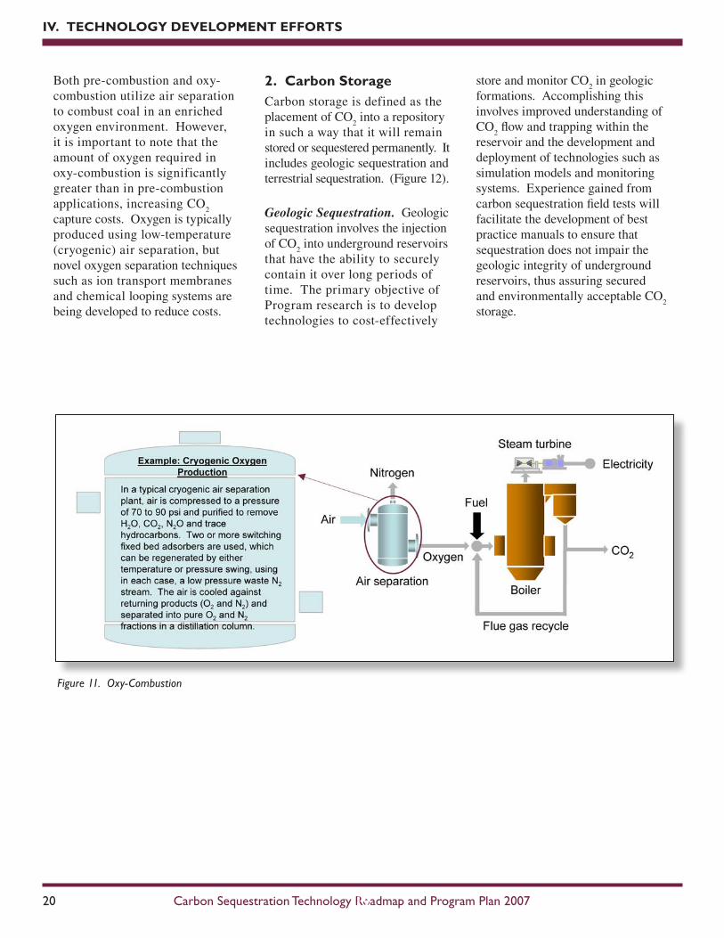
Oxygen combustion (oxy-combustion). The objective of pulverized coal oxygen-fired combustion is to combust coal in an enriched oxygen environment using pure oxygen diluted with recycled CO
2 or H
2O (Figure 11). Under
these conditions, the primary products of combustion are CO
2 and H
2O, and the CO
2 can
be captured by condensing the water in the exhaust stream. Oxy-combustion offers several additional benefits, as determined
through large-scale laboratory testing and systems analysis:
• A 60-70 percent reduction in NOx
emissions compared to air-fired combustion, mainly due to flue gas recycle, but also from reduced thermal NO
x levels due to lower
available nitrogen. Some nitrogen is still available from coal nitrogen and air infiltrations.
• Increased mercury removal. Boiler tests of oxy-fuel combustion using
Powder River Basin (PRB) coal resulted in increased oxidation of mercury, facilitating downstream mercury removal in the electrostatic precipitator and flue gas desulfurization systems.
• Applicability to new and existing coal-fired power plants. The key process principles involved in oxy-combustion have been demonstrated commercially (including air separation and flue gas recycle).
Both pre-combustion and oxy-combustion utilize air separation to combust coal in an enriched oxygen environment. However, it is important to note that the amount of oxygen required in oxy-combustion is significantly greater than in pre-combustion applications, increasing CO
2
capture costs. Oxygen is typically produced using low-temperature (cryogenic) air separation, but novel oxygen separation techniques such as ion transport membranes and chemical looping systems are being developed to reduce costs.
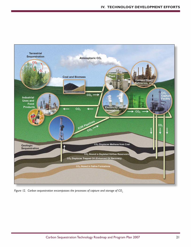
2. Carbon StorageCarbon storage is defined as the placement of CO
2 into a repository
in such a way that it will remain stored or sequestered permanently. It includes geologic sequestration and terrestrial sequestration. (Figure 12).
Geologic Sequestration. Geologic sequestration involves the injection of CO
2 into underground reservoirs
that have the ability to securely contain it over long periods of time. The primary objective of Program research is to develop technologies to cost-effectively
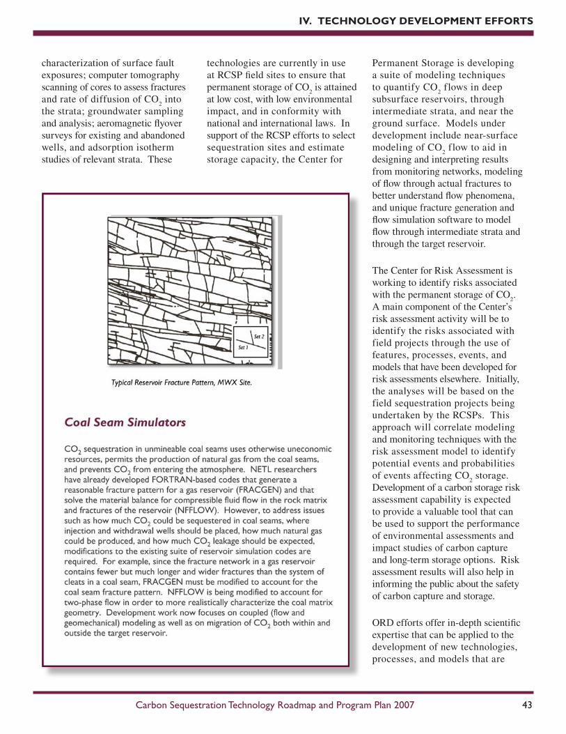
IV. TEChNOLOGy DEVELOPMENT EFFORTS
Figure 11. Oxy-Combustion
store and monitor CO2 in geologic
formations. Accomplishing this involves improved understanding of CO
2 flow and trapping within the
reservoir and the development and deployment of technologies such as simulation models and monitoring systems. Experience gained from carbon sequestration field tests will facilitate the development of best practice manuals to ensure that sequestration does not impair the geologic integrity of underground reservoirs, thus assuring secured and environmentally acceptable CO
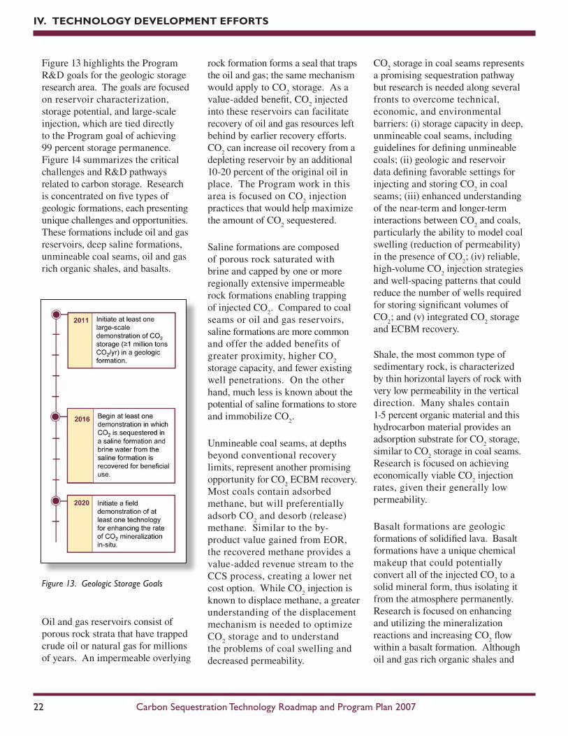
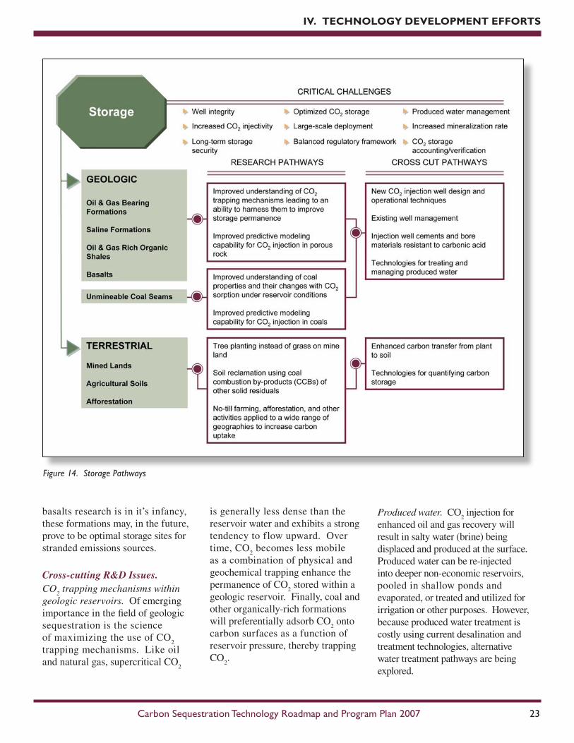
Figure 13 highlights the Program R&D goals for the geologic storage research area. The goals are focused on reservoir characterization, storage potential, and large-scale injection, which are tied directly to the Program goal of achieving 99 percent storage permanence. Figure 14 summarizes the critical challenges and R&D pathways related to carbon storage. Research is concentrated on five types of geologic formations, each presenting unique challenges and opportunities. These formations include oil and gas reservoirs, deep saline formations, unmineable coal seams, oil and gas rich organic shales, and basalts.
Oil and gas reservoirs consist of porous rock strata that have trapped crude oil or natural gas for millions of years. An impermeable overlying
rock formation forms a seal that traps the oil and gas; the same mechanism would apply to CO
2 storage. As a
value-added benefit, CO2 injected
into these reservoirs can facilitate recovery of oil and gas resources left behind by earlier recovery efforts. CO
2 can increase oil recovery from a
depleting reservoir by an additional 10-20 percent of the original oil in place. The Program work in this area is focused on CO
2 injection
practices that would help maximize the amount of CO
2 sequestered.
Saline formations are composed of porous rock saturated with brine and capped by one or more regionally extensive impermeable rock formations enabling trapping of injected CO
2. Compared to coal
seams or oil and gas reservoirs, saline formations are more common and offer the added benefits of greater proximity, higher CO
2
storage capacity, and fewer existing well penetrations. On the other hand, much less is known about the potential of saline formations to store and immobilize CO
2.
Unmineable coal seams, at depths beyond conventional recovery limits, represent another promising opportunity for CO
2 ECBM recovery.
Most coals contain adsorbed methane, but will preferentially adsorb CO
2 and desorb (release)
methane. Similar to the by-product value gained from EOR, the recovered methane provides a value-added revenue stream to the CCS process, creating a lower net cost option. While CO
2 injection is
known to displace methane, a greater understanding of the displacement mechanism is needed to optimize CO
2 storage and to understand
the problems of coal swelling and decreased permeability.
CO2 storage in coal seams represents
a promising sequestration pathway but research is needed along several fronts to overcome technical, economic, and environmental barriers: (i) storage capacity in deep, unmineable coal seams, including guidelines for defining unmineable coals; (ii) geologic and reservoir data defining favorable settings for injecting and storing CO
2 in coal
seams; (iii) enhanced understanding of the near-term and longer-term interactions between CO
2 and coals,
particularly the ability to model coal swelling (reduction of permeability) in the presence of CO
2; (iv) reliable,
high-volume CO2 injection strategies
and well-spacing patterns that could reduce the number of wells required for storing significant volumes of CO
2; and (v) integrated CO
2 storage
and ECBM recovery. Shale, the most common type of sedimentary rock, is characterized by thin horizontal layers of rock with very low permeability in the vertical direction. Many shales contain 1-5 percent organic material and this hydrocarbon material provides an adsorption substrate for CO
2 storage,
similar to CO2 storage in coal seams.
Research is focused on achieving economically viable CO
2 injection
rates, given their generally low permeability.
Basalt formations are geologic formations of solidified lava. Basalt formations have a unique chemical makeup that could potentially convert all of the injected CO
2 to a
solid mineral form, thus isolating it from the atmosphere permanently. Research is focused on enhancing and utilizing the mineralization reactions and increasing CO
2 flow
within a basalt formation. Although oil and gas rich organic shales and
basalts research is in it’s infancy, these formations may, in the future, prove to be optimal storage sites for stranded emissions sources.
Cross-cutting R&D Issues.CO
2 trapping mechanisms within
geologic reservoirs. Of emerging importance in the field of geologic sequestration is the science of maximizing the use of CO
2
trapping mechanisms. Like oil and natural gas, supercritical CO
2
is generally less dense than the reservoir water and exhibits a strong tendency to flow upward. Over time, CO
2 becomes less mobile
as a combination of physical and geochemical trapping enhance the permanence of CO
2 stored within a
geologic reservoir. Finally, coal and other organically-rich formations will preferentially adsorb CO
2 onto
carbon surfaces as a function of reservoir pressure, thereby trapping CO
2.
Produced water. CO2 injection for
enhanced oil and gas recovery will result in salty water (brine) being displaced and produced at the surface. Produced water can be re-injected into deeper non-economic reservoirs, pooled in shallow ponds and evaporated, or treated and utilized for irrigation or other purposes. However, because produced water treatment is costly using current desalination and treatment technologies, alternative water treatment pathways are being explored.
Proper engineering of injection wells is vitally important for CO
2 storage
projects. Improving the integrity of future wells requires the development of novel cements, construction procedures to mitigate leakage, and sensors to monitor well integrity. In addition, novel drilling techniques for advanced wells that provide a high CO
2 injection rate in the target
formation should be pursued to reduce the number of wells needed for injection, thereby minimizing potential leakage pathways for CO
2.
Lateral well drilling capabilities, combined with advanced reservoir characterization, could also facilitate placement of injection points that allow CO
2 flow through
low permeability regions, further expanding CO
2 storage capacity.
Terrestrial Sequestration. Terrestrial carbon sequestration is defined as the net removal of CO
2 from the
atmosphere by the soil and plants and/or the prevention of CO
2 net
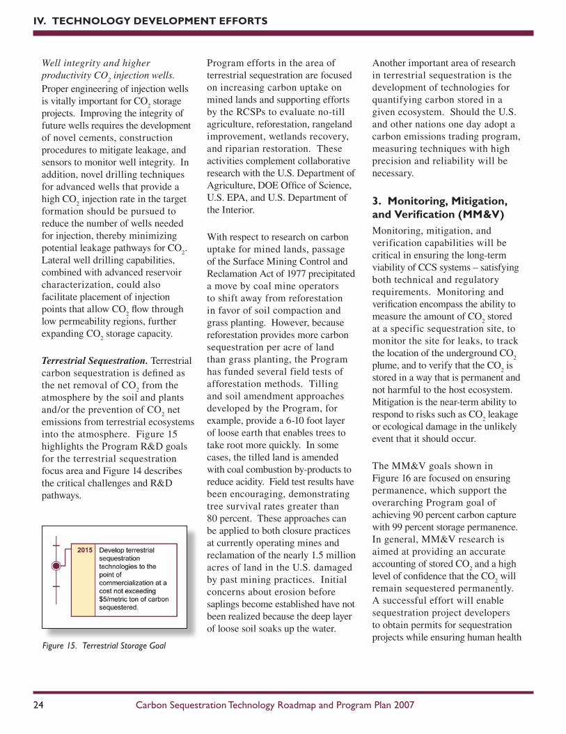
emissions from terrestrial ecosystems into the atmosphere. Figure 15 highlights the Program R&D goals for the terrestrial sequestration focus area and Figure 14 describes the critical challenges and R&D pathways.
Another important area of research in terrestrial sequestration is the development of technologies for quantifying carbon stored in a given ecosystem. Should the U.S. and other nations one day adopt a carbon emissions trading program, measuring techniques with high precision and reliability will be necessary.
3. Monitoring, Mitigation, and Verification (MM&V)Monitoring, mitigation, and verification capabilities will be critical in ensuring the long-term viability of CCS systems – satisfying both technical and regulatory requirements. Monitoring and verification encompass the ability to measure the amount of CO
2 stored
at a specific sequestration site, to monitor the site for leaks, to track the location of the underground CO
2
plume, and to verify that the CO2 is
stored in a way that is permanent and not harmful to the host ecosystem. Mitigation is the near-term ability to respond to risks such as CO
2 leakage
or ecological damage in the unlikely event that it should occur.
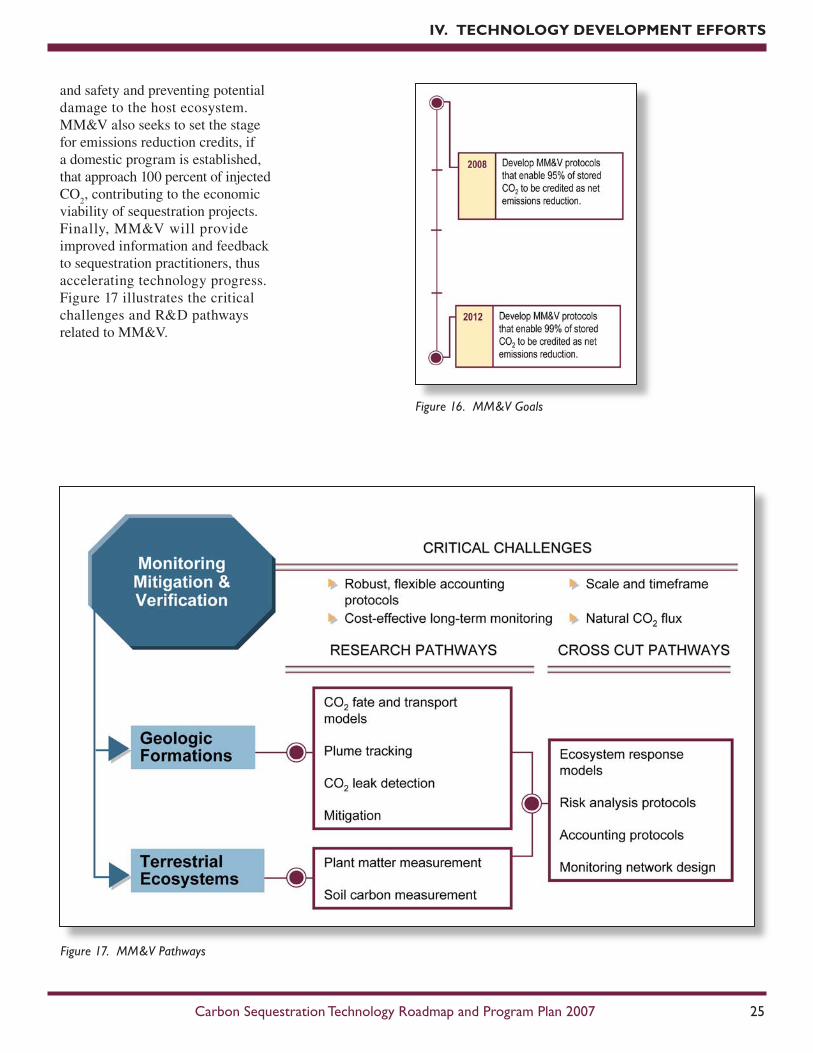
The MM&V goals shown in Figure 16 are focused on ensuring permanence, which support the overarching Program goal of achieving 90 percent carbon capture with 99 percent storage permanence. In general, MM&V research is aimed at providing an accurate accounting of stored CO
2 and a high
level of confidence that the CO2 will
remain sequestered permanently. A successful effort will enable sequestration project developers to obtain permits for sequestration projects while ensuring human health
Program efforts in the area of terrestrial sequestration are focused on increasing carbon uptake on mined lands and supporting efforts by the RCSPs to evaluate no-till agriculture, reforestation, rangeland improvement, wetlands recovery, and riparian restoration. These activities complement collaborative research with the U.S. Department of Agriculture, DOE Office of Science, U.S. EPA, and U.S. Department of the Interior.
With respect to research on carbon uptake for mined lands, passage of the Surface Mining Control and Reclamation Act of 1977 precipitated a move by coal mine operators to shift away from reforestation in favor of soil compaction and grass planting. However, because reforestation provides more carbon sequestration per acre of land than grass planting, the Program has funded several field tests of afforestation methods. Tilling and soil amendment approaches developed by the Program, for example, provide a 6-10 foot layer of loose earth that enables trees to take root more quickly. In some cases, the tilled land is amended with coal combustion by-products to reduce acidity. Field test results have been encouraging, demonstrating tree survival rates greater than 80 percent. These approaches can be applied to both closure practices at currently operating mines and reclamation of the nearly 1.5 million acres of land in the U.S. damaged by past mining practices. Initial concerns about erosion before saplings become established have not been realized because the deep layer of loose soil soaks up the water.
and safety and preventing potential damage to the host ecosystem. MM&V also seeks to set the stage for emissions reduction credits, if a domestic program is established, that approach 100 percent of injected CO
2, contributing to the economic
viability of sequestration projects. Finally, MM&V will provide improved information and feedback to sequestration practitioners, thus accelerating technology progress. Figure 17 illustrates the critical challenges and R&D pathways related to MM&V.
Geologic Formations.Monitoring and verification activities for geologic sequestration encompass three components:
• Modeling. Modeling involves simulating the underground conditions that influence the behavior of CO
2 injected
into geologic formations and characterizing any resulting geomechanical changes to the reservoir. Comprehensive CO
2
storage reservoir modeling will enable researchers to predict how
CO2 plumes will flow and become
hydrodynamically trapped in the short term and to understand the effects of chemical reactions (and other mechanisms) that will immobilize CO
2 over the
longer term. These models will help operators reduce the risks associated with inducing fractures in caprock and reactivating faults during injection. Such modeling capabilities engender confidence that injected CO
2 will remain
securely stored before injection commences. Comprehensive CO
2
storage modeling does not just examine the target reservoir but also the potential pathways that
fugitive CO2 may follow. The
ability to model fluid transport and chemical reactions within geologic reservoirs already exists. Models are currently in use to manage secondary and tertiary oil recovery and to examine the long-term fate of industrial hazardous wastes disposed underground. Activities are underway to adapt these models to geologic CO
2
storage. The Program seeks to acquire the detailed data needed to support reliable operation of these models (i.e., chemical reaction kinetics and two- and three-phase vapor/liquid equilibrium data at supercritical
conditions) and to develop integrated models that support early small-scale pilot field tests.
• Plume tracking. Underground plume tracking provides the ability to “map” the injected CO
2
and track its movement and fate through a reservoir. The ability to verify the location of injected CO
2
over time is necessary to assure storage permanence. Seismic surveys (e.g., 4-D seismic, time-lapse vertical seismic profiling) and sampling from wells (borehole logging) are key technologies used for plume tracking. Because supercritical CO
2 is less dense and more
compressible than saline water, seismic waves travel through it at a different velocity. As a result of the velocity contrast, the presence of free CO
2 in a saline formation
leaves a distinct seismic signature, as seen at the Weyburn (Canada) and Frio (Texas) field sites. Observation wells instrumented to monitor reservoir conditions such as pressure, temperature, and other properties are another important source of information for plume tracking. Much can be learned from the monitoring efforts used by CO
2 EOR projects
and particularly by the gas storage industry. The Program work in this area is focused on adapting these technologies for use in CO
2 sequestration applications,
where knowledge gained from field tests will help optimize CO
2
storage and identify the least-cost approach to effective MM&V.
• Leak detection. Beyond serving as backstops for modeling and plume tracking, CO
2 leak
detection systems provide
critical measures of whether CO
2 is escaping from the storage
reservoir. One challenge for leak detection is the need to cover large areas cost-effectively at the required resolution. The CO
2
plume from an injection of one million tons of CO
2 per year in a
deep saline formation for 20 years could be spread over a horizontal area of 15 square miles or more.
There are important interconnections among these three areas. Data from plume tracking enables validation of reservoir models; robust reservoir models enable operators to design and better interpret data from plume tracking; and models and plume tracking help focus leak detection efforts on high-risk areas. Such information provides a basis for addressing public and regulatory concerns and ensures that no adverse events are likely to occur in the storage formation.
Mitigation approaches. The science and technology of remediating CO
2 leakage is still
emerging. Storing CO2 in rigorously
selected geological formations such as at Weyburn (Canada), Sleipner (Norway), and In Salah (Algeria) suggest that the inherent risks and potential quantities of CO
2 leakage
will be minimal. In the unlikely event that CO
2 leakage occurs, steps
can be taken to arrest the flow of CO
2 and mitigate the impacts. For
example, lowering the pressure within the CO
2 storage reservoir by
stopping injection could reduce the driving force for CO
2 flow and close
a leaking fault or fracture. Other options include forming a “pressure barrier” by increasing the pressure in the reservoir into which CO
2 is
leaking or by intercepting the CO2
leakage paths. Another strategy is
plugging the region where leakage is occurring with low permeability materials. Additional research in this area is needed, especially on quantifying the costs associated with different remedial actions.
MM&V for Terrestrial Ecosystems. MM&V activities focused on terrestrial ecosystems encompass three components:
• Organic matter measurement. Traditional methods for measuring carbon in terrestrial ecosystems (e.g., measuring tree diameters and analyzing soil samples in an off-site laboratory) are labor-intensive and costly. The Program is developing automated technologies that provide more detailed and timely information at lower cost for use in managing a sequestration site.
• Soil carbon measurement. Soil carbon offers the potential for long-term CO
2 storage. The
Program is developing automated technologies for measuring soil carbon.
• Modeling. Detailed models are used to extrapolate the results of carbon uptake activities from random samples to an entire plot and to estimate the net increase in carbon storage relative to a case without enhanced carbon uptake. Economic models show accumulations of emissions credits and revenues versus an initial investment.
These three components have a vital role in proving the permanence of CO
2 storage in terrestrial ecosystems.
Continued research is needed, particularly since quantifying CO
is more challenging than identifying leaks in geologic storage formations. In addition, the development of robust and flexible accounting protocols that function within future regulatory and market regimes is critical to the verification of long-term storage in terrestrial ecosystems.
Accounting protocols. Monitoring and measurement systems must provide certainty to project owners, regulators and the global environmental community that sequestration projects are achieving and sustaining expected levels of CO
2 permanence. A
key challenge facing the carbon sequestration community, therefore, is the development of robust, equitable, and transparent accounting
Two large sources of methane and GHGs in the U.S. – landfills and coal mines – represent priority R&D pathways for the Carbon Sequestration Program (Figure 18). In one pathway, the produced methane is combusted, reducing the carbon’s GHG effect by a factor of ten. In the other pathway, the produced methane is captured and utilized.
Landfill gas is typically a 50/50 mixture of methane and CO
2,
with trace amounts of heavier hydrocarbons. The Program is exploring methods to enhance the biological utilization of methane in landfill covers and studying management practices at bioreactor landfills to control the conditions
IV. TEChNOLOGy DEVELOPMENT EFFORTS
mechanisms with the flexibility to function within future regulatory and market regimes. 4. Non-CO2 Greenhouse Gas Control
According to the EIA, non-CO
2 greenhouse gas emissions
contributed 16 percent of the total U.S. GHG emissions in 2005. Since many non-CO
2 greenhouse gases
(e.g., methane, nitrous oxide, and certain refrigerants) have significant economic value, emissions can often be captured or avoided at low net cost. The Carbon Sequestration Program aims to tap the economic value of fugitive methane emissions by developing innovative capture and gas upgrading technologies.
within the landfill to promote or suppress methane production. The Program is also exploring techniques to enhance methane capture and use for energy generation, including the injection of landfill gas into unmineable coal seams to harness the natural ability of coal to adsorb CO
2, thus replacing and releasing
methane for ECBM.
Methane emissions from coal mines represent about 10 percent of U.S. anthropogenic methane emissions. Ventilation air methane (VAM) is the largest source of coal mine methane – accounting for about half of the methane emitted from
5. Breakthrough Concepts
DOE is committed to fostering the innovative potential of industry and academia. The Breakthrough Concepts focus area serves as an incubator for CO
2 capture, storage, and
conversion concepts with the potential to provide step-change improvements in process efficiency, energy use, and cost. Figure 19 illustrates some of the research pathways being pursued in the Breakthrough Concepts focus area.
In October 2006, DOE announced the selection of nine projects aimed at developing novel and cost-effective technologies for CO
2 capture from
coal-fired power plants. Two of these projects have matured from Breakthrough Concepts selections under a 2004 joint DOE/National Academies of Science (NAS) solicitation to the Core R&D CO
2
Capture focus area, where they will be advanced to the pre-pilot scale. One project will focus on the development of a new class of liquid absorbents called ionic liquids for efficient post-combustion capture of CO
2 from coal-fired power plants.
The other project will develop a process that uses novel microporous metal organic frameworks having extremely high adsorption capacities for the removal of CO
2 from coal-
fired power plant flue gas. The Program also supports research in membranes and mineralization, including a project to create microbes that biologically sequester CO
2 by
converting it to other value-added chemicals that have use in certain drug compounds, agricultural and food production, and biodegradable plastics.
U.S. coal mines. The Program is pursuing technologies to cost-effectively convert the methane in coal mine ventilation air to CO
2.
Methane can also be recovered from mine degasification systems, where methane concentrations are much higher (30-90 percent) than in coal mine VAM (0.3-1.5 percent). Here, the Program aims to develop and deploy cost-effective technologies to upgrade gas to pipeline quality specifications. The Program is collaborating with the U.S. EPA, which has both coal mine methane and landfill gas outreach programs.
Geographic differences in fossil fuel use and potential sequestration storage sites across the U.S. dictate the use of regional approaches in addressing CO
2 sequestration. DOE has created
a network of seven Regional Carbon Sequestration Partnerships to develop the technology, infrastructure, and regulations necessary to implement CO
2 sequestration in different regions
of the Nation. Underlying this regional partnership approach is the
belief that local entities, organizations, and citizens will contribute expertise, experience, and perspectives that more accurately represent the concerns and desires of a given region, resulting in the development and application of technologies better suited to that region.
Collectively, the seven RCSPs represent regions encompassing 97 percent of coal-fired CO
2 emissions, 97 percent of
industrial CO2 emissions, 96 percent of
the total land mass, and essentially all the geologic sequestration sites in the U.S. potentially available for carbon storage. The RCSPs are evaluating
numerous sequestration approaches to assess which approaches are best suited for specific regions of the country and are developing the framework needed to validate and potentially deploy the most promising CCS technologies. The two sequestration options that have evolved from the Core R&D element as priorities for near-term deployment are:
• Geologic Sequestration – CO2
injection into different geologic formations including depleted oil and natural gas fields, unmineable coal seams, saline formations, shale, and basalt outcrops
• Terrestrial Sequestration – carbon sequestration in soils and organic material through the restoration of agricultural fields, grasslands, rangeland, wetlands, and forests or by altering the management of these assets
Among the seven RCSP Regions, geologic sequestration sites differ in their lithology as well as their locations relative to CO
2 emission
sources and pipelines. Some regions have an abundance of different types of geologic formations, while opportunities in other regions are dominated by a specific formation type. Terrestrial sequestration options vary across regions based on differences in average temperature, topography, soil type, amount of rainfall, and other factors.
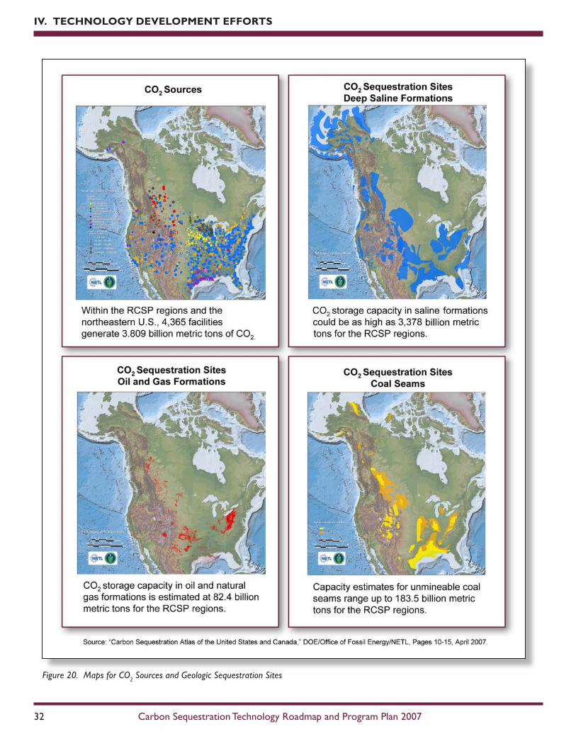
The process of sequestering carbon dioxide involves identifying sources that produce CO
2 and identifying
sequestration sites where the CO
2 can be stored. Based on
data assembled for the Carbon Sequestration Atlas of the United States and Canada, Table 1 shows that 4,365 identified stationary sources in the seven RCSP Regions and the northeastern U.S. generate about 3.809 billion metric tons of CO
2 annually. The aggregate CO
2
sink capacity – including saline formations, unmineable coal seams, and oil and natural gas reservoirs – is estimated to range up to 3,643 billion metric tons, enough to sequester CO
2 emissions at current
annual generation rates for hundreds of years. The formation maps in Figure 20 show the geographic
locations of these CO2 sources and
potential geologic sequestration sites. The RCSPs include more than 350 organizations and span 41 states, three Indian nations, and four Canadian provinces. The partners include utilities, oil and natural gas companies, ethanol producers, agricultural industry, other industrial partners, state and local government organizations, regional universities, national laboratories, and special interest groups representing industrial and environmental communities. Table 2 provides website, acronym, lead organization, and geographic coverage information for the RCSPs.
IV. TEChNOLOGy DEVELOPMENT EFFORTS
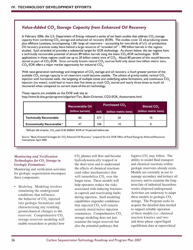
Table 1. Capacity Estimates of CO2 Sources and Geologic Sequestration Sites
Each of the RCSPs is described below in terms of participating organizations, strategic focus on field testing, and types of CO
2 storage opportunities being
evaluated. The BigSkyCarbonSequestrationPartnership(BigSky) is comprised of 66 partners and native American tribes. The Big Sky Partnership has extensive basalt formations, saline formations, and oil and natural gas reservoirs that could be used as storage sites. Geologic field tests are planned in deep saline and depleted oil fields. The Big Sky Partnership is also exploring the Region’s potential to store CO
2 in agricultural soils, rangeland
soils, and forests. Three terrestrial tests are planned to examine CO2 uptake.
The MidwestGeologicalSequestrationConsortium(MGSC) is comprised of 21 partners and is assessing the ability of geological formations in the Illinois Basin to store CO
2 in unmineable coal seams, mature oil fields, and
deep saline formations. Highly favorable storage areas may exist in this Region since two or more potential CO
2 sink types are vertically stacked in
some localities. MGSC will also investigate CO2 capture technologies and
the costs of transporting large quantities of CO2 via pipeline. Six small pilot
projects will evaluate EOR by CO2 flooding, CO
2 sequestration in unmineable
coal seams, and CO2 injection into deep saline formations up to 10,000 feet
below the Earth’s surface.
The MidwestRegionalCarbonSequestrationPartnership(MRCSP) has 36 partners and is determining the CO
2 storage potential of various geologic
formations, particularly saline formations. MRCSP will conduct three CO2
injection field tests in deep geologic formations in the Region to demonstrate the safety and effectiveness of geologic sequestration systems. MRCSP will also conduct three terrestrial sequestration field tests to explore how naturally stored carbon can be measured and monitored and how carbon credits could be traded in voluntary GHG markets.
The PlainsCO2ReductionPartnership(PCOR) consists of 63 partners working to demonstrate the potential of depleted oil fields, and unmineable lignite coals to store CO
2 emissions. Geologic tests are planned in the oil-
bearing Keg River and Duperow formations in Alberta province and North Dakota, respectively, while a coal seam sequestration test is planned for the Williston Basin in North Dakota. The Partnership also plans to demonstrate that carbon can be stored in the native grasslands and through the restoration of wetlands. Terrestrial field tests are planned for the Great Plains Prairie Pothole wetlands complex.
The SoutheastRegionalCarbonSequestrationPartnership(SECARB) has 77 partners working to characterize carbon sources and potential sequestration sites in the Southeast; identify the most promising capture, sequestration, and transport options; and address issues for technology deployment. SECARB will conduct four geologic sequestration field tests covering EOR stacked formations along the Gulf Coast, coal seam sequestration and coalbed methane recovery, and saline formations.
The SouthwestRegionalPartnershiponCarbonSequestration(SWP) has 52 partners in eight states, including the Navajo nation. SWP is investigating a variety of carbon sink targets. The Partnership will leverage 30 years of EOR experience in the Region to determine the potential of oil, coal, and saline formations to store CO
2 emissions. Field testing of ECBM production
with carbon sequestration is planned. The Partnership is also investigating the potential of terrestrial systems in the Southwest to store CO
2, including a
riparian restoration project using produced water from the ECBM field test.
The WestCoastRegionalCarbonSequestrationPartnership(WESTCARB) is comprised of 78 partners dedicated to evaluating regional CCS opportunities. The Partnership is examining the sequestration potential in depleted oil, unmineable coal, and deep saline formations. One EOR and saline storage test is planned in California and one saline storage test in Arizona. Terrestrial sequestration pilot projects will be conducted in Oregon and California. The Partnership will also investigate the use of reforestation and fire suppression to mitigate CO
2. RCSP ProgramThe RCSP Program was initiated in September 2003 through an open competitive solicitation process that required a minimum 20 percent cost share from the prospective awardees. As Figure 21 illustrates, the RCSP Program is being implemented in three interrelated phases. Levels of DOE funding without cost shares are shown.
• Characterization Phase (FY 2003 – FY 2005)
• Validation Phase (FY 2005 – FY 2009)
• Deployment Phase (FY 2008 – FY 2017)
Actual cost shares for the RCSPs through the Characterization and Validation Phases have ranged from the 20 percent minimum to as high
as 52 percent. As a group, the seven RCSPs have provided more than 31 percent in cost sharing through the first two phases.
Even though the RCSP Program is being implemented in three phases, it should be viewed as an integrated whole, with many of the goals and objectives transitioning from one phase to the next. Accomplishments and results from the Characterization Phase have helped to refine goals and activities in the Validation Phase, and results from the Validation Phase are expected to flow into and enhance the Deployment Phase.
The RCSP Program encourages and requires open information sharing among its members. DOE and the RCSPs sponsor both general workshops and more focused technology area Working Group meetings to facilitate information
exchange. These meetings are important tools that strengthen the overall RCSP Program. Although each RCSP has its own objectives and field tests, mutual cooperation has been an important part of the Program to date. These workshops and formal Working Group activities were initiated during the Characterization Phase, have continued into the Validation Phase, and will likely be an important aspect of the Deployment Phase as well.
3. Characterization PhaseThe Characterization Phase, completed in 2005, focused on characterizing regional opportunities for carbon capture and storage, identifying regional CO
2 sources,
and identifying priority opportunities for field tests. Each RCSP developed decision support systems that house regional geologic data on CO
sources to complete source-sink matching models. Each RCSP also researched project tools necessary to model and measure the fate and spread of CO
2 after injection.
Combined with public outreach and education programs conducted by the RCSPs during the Characterization Phase, these activities show that CCS is a viable option to mitigate CO
2 emissions. In preparation of the
Validation and Deployment Phases, the RCSPs gathered data necessary to prepare and conduct geologic and terrestrial field tests, and made the following key accomplishments:
• Established a national network of companies and professionals working to support sequestration deployments. The RCSPs brought an enormous amount of capability and experience together to work on the challenge of infrastructure development. Together with DOE, the RCSPs secured the active participation of more than 500 individuals representing more than 350 industrial companies, engineering firms, state agencies, non-governmental organizations, and other supporting organizations.
• Raised awareness and support for CCS as a GHG mitigation option. Each RCSP developed creative and innovative approaches to outreach and education. Articles about sequestration have been placed in local newspapers, documentaries have been shown on public television, and several people involved in the RCSPs made appearances on local television programs. All seven RCSPs developed websites that describe their activities and
several RCSPs experimented with innovative, internet-based outreach efforts, including a modified chat room for fielding questions about sequestration and town hall style meetings.
• Advanced understanding of permitting requirements for future CCS projects. To comply with public and regulatory
requirements and to address possible safety and environmental risks, CCS projects will require permits. Working in collaboration with the Interstate Oil and Gas Compact Commission (IOGCC) and in consultation with the U.S. EPA, the RCSPs assessed requirements and procedures for permitting future commercial sequestration deployments.
• Identified priority opportunities for sequestration field tests. The RCSPs identified high priority opportunities within their Regions that target select field tests during the Validation Phase.
• Established a series of protocols for project implementation, accounting, and contracts. RCSP activities in this area focused on the development of accounting protocols and support for state or national GHG accounting registries.
4. Validation PhaseThe Validation Phase focuses on field tests to validate the efficacy of CCS technologies in a variety of geologic and terrestrial storage sites throughout the U.S. and Canada. Using the extensive data and information gathered during the Characterization Phase, the seven RCSPs identified the most promising opportunities for carbon sequestration in their Regions and are performing 25 geologic field tests (Figure 22) and 11 terrestrial field tests (Figure 23). In addition, the RCSPs are verifying regional CO
2
sequestration capacities, satisfying project permitting requirements, and conducting public outreach and education activities.
The first four geologic projects listed in Figure 22 are large-scale injections where a commercial partner is already injecting CO
2
into depleted oil reservoirs and unmineable coal seams for EOR and/or ECBM recovery applications. The partner is focusing its efforts to determine the fate of the injected CO
2 through predictive modeling and
monitoring activities. The remaining projects will involve injection of a relatively small amount of CO
2 into
unmineable coal seams, oil and natural gas reservoirs, and saline formations to assess the sequestration potential of these geologic sites. The RCSPs are working to develop injection and monitoring wells, coordinate injection operations, conduct reservoir modeling, and monitor the fate of the CO
2. In
addition, the RCSPs are conducting public outreach activities and satisfying the necessary permit applications. To successfully conduct these geologic field tests, the RCSPs are collaborating with industrial partners that are providing the financial and technical support necessary for the success of the program.
The field tests conducted during the Validation Phase address the following goals:
• Validate and refine current CO2
reservoir models for various geologic sequestration sites
• Collect physical data to confirm capacity and injectivity estimates made during the Characterization Phase
• Demonstrate the effectiveness of MM&V technologies to measure CO
2 movement in the reservoirs and
confirm the integrity of the seals
• Develop guidelines for well completion, operations, and abandonment to maximize storage potential and mitigate leakage
• Develop strategies that can be used to optimize the storage capacity for various sink types
To achieve these primary Validation Phase goals, each RCSP has further established its own supporting goals. Many of these supporting goals and actions were created as a logical continuation of goals completed and/or specific accomplishments attained during the Characterization Phase. The RCSPs are part of a programmatic initiative that is closely coordinated through DOE and the Working Groups.
In addition to the goals related to the field test projects, the RCSPs continue to improve on the work conducted during the Characterization Phase. The RCSPs will update information collected on CO
2 stationary sources
and potential sequestration sites as additional data and analytical procedures become available. A common economic modeling
approach for CO2 capture will be
developed based on preliminary economic models of available and emerging capture technologies created during the Characterization Phase. Storage capacity estimates for saline formations will be refined in the Validation Phase and beyond using a common methodology developed by the RCSPs during the Characterization Phase. Instrumentation evaluated and tested during the Characterization Phase to follow CO
2 injection, plume
migration, and leak detection will be used to develop protocols for site selection and monitoring.
5. Deployment PhaseThe Deployment Phase, scheduled to begin in FY 2008 and run through FY 2017, will demonstrate at large scale that CO
2 capture,
transportation, injection, and storage can be achieved safely, permanently, and economically. DOE will provide up to $470M in federal support for the RCSPs over 10 years. An additional 20 percent cost share will be provided by each RCSP.
These large-volume deployment tests will provide concurrent input to the FutureGen Initiative, which will produce both hydrogen and electricity from a highly efficient and technologically sophisticated power plant while capturing and sequestering the CO
2 emissions.
The geologic structures to be tested during these large-volume sequestration tests could become candidate sites for future near zero emissions power plants.
The primary goal of the Deployment Phase is the development of large-scale CCS projects across North America, where large volumes of CO
2 will be injected into a
geologic formation representative of a relatively large storage capacity for each Region. The injection will continue over several years. Recognizing that CO
2 sources vary
widely from Region to Region and that some Regions will have limited access to large volumes of CO
2,
injection volumes may vary. The RCSPs, however, will be expected to maximize CO
2 injection volumes
that fully utilize the infrastructure of the Region. Projects that procure CO
2 from natural gas processing
plants or natural vents may inject one million tons or more of CO
2 per year,
depending upon cost and availability.
The Deployment Phase tests will be implemented in three stages which will test key technologies during the demonstration and deployment: (1) site selection, characterization, National Environmental Policy Act (NEPA) compliance, permitting, and infrastructure development; (2) CO
2
injection and monitoring operations; and (3) site closure, post injection monitoring, and analysis. While projects in the Validation Phase are designed to demonstrate that regional sequestration sites have the potential to store thousands of years’ worth of CO
2 emissions in the U.S., the large-
volume sequestration tests in the Deployment Phase will also address practical issues such as sustainable injectivity, well design for both integrity and increased capacity, and reservoir behavior with respect to prolonged injection. Such issues can only be addressed by scaling up the size and duration of sequestration projects. Key operational issues and lessons learned will vary since each Region will have different geologic formations, overlying seals, and structural issues that can affect the safe and effective storage of CO
C.NETLOfficeofResearchandDevelopmentNETL conducts carbon capture and storage R&D through its Office of Research and Development (ORD) in four focus areas – Computational and Basic Sciences, Energy System Dynamics, Geological and Environmental Systems, and Materials Science – that build upon NETL R&D strengths and address long-range issues central to continued fossil fuel use. Science-based research and analysis in areas relating specifically to CCS is conducted within the Geological and Environmental Systems focus area and is known as the NETL Carbon Management Research Program.
Using in-house facilities and resources, researchers in the Carbon Management Research Program conduct the research and analysis needed to develop energy-efficient and cost-effective methods that can manage CO
2 emissions from energy
production. NETL has established unique Centers of Research in carbon capture, permanent storage, and risk assessment associated with CCS technology development. These Centers of Research directly support the Carbon Sequestration Program as well as collaborative efforts with the RCSPs. Examples of ongoing interactions between the Centers of Research and the RCSPs include risk assessments with the Southwest Regional Partnership, CO
2 storage
verification in coal seams with the Southeast and Southwest Regional Partnerships, and coal swelling modeling with the Midwest Geological Sequestration Consortium.
The NETL Center for Carbon Capture develops and evaluates breakthrough approaches that have the potential to substantially reduce the complexity
and energy intensity of CO2 capture.
Research in this Center focuses on novel or revolutionary approaches that remove CO
2 during energy production
rather than scrubbing or eliminating it from a by-product stream. The development of membranes to separate CO
2 from combustion gases
is one example of this research; once separated, the CO
2 is easily captured
and can then be sequestered. Oxy-fuel firing is another process under development, whereby CO
2 can be
separated from exhaust gases by
simply condensing out the water. Researchers often use a combination of laboratory studies and numerical models to evaluate novel approaches to carbon capture. Relying on their expertise in modeling and simulation, researchers extrapolate laboratory findings to projected applications before engaging in large-scale testing.
The Center for Permanent Storage is researching several CO
2
storage verification techniques, including soil gas measurements;
characterization of surface fault exposures; computer tomography scanning of cores to assess fractures and rate of diffusion of CO
2 into
the strata; groundwater sampling and analysis; aeromagnetic flyover surveys for existing and abandoned wells, and adsorption isotherm studies of relevant strata. These
technologies are currently in use at RCSP field sites to ensure that permanent storage of CO
2 is attained
at low cost, with low environmental impact, and in conformity with national and international laws. In support of the RCSP efforts to select sequestration sites and estimate storage capacity, the Center for
Permanent Storage is developing a suite of modeling techniques to quantify CO
2 flows in deep
subsurface reservoirs, through intermediate strata, and near the ground surface. Models under development include near-surface modeling of CO
2 flow to aid in
designing and interpreting results from monitoring networks, modeling of flow through actual fractures to better understand flow phenomena, and unique fracture generation and flow simulation software to model flow through intermediate strata and through the target reservoir.
The Center for Risk Assessment is working to identify risks associated with the permanent storage of CO
2.
A main component of the Center’s risk assessment activity will be to identify the risks associated with field projects through the use of features, processes, events, and models that have been developed for risk assessments elsewhere. Initially, the analyses will be based on the field sequestration projects being undertaken by the RCSPs. This approach will correlate modeling and monitoring techniques with the risk assessment model to identify potential events and probabilities of events affecting CO
2 storage.
Development of a carbon storage risk assessment capability is expected to provide a valuable tool that can be used to support the performance of environmental assessments and impact studies of carbon capture and long-term storage options. Risk assessment results will also help in informing the public about the safety of carbon capture and storage.
ORD efforts offer in-depth scientific expertise that can be applied to the development of new technologies, processes, and models that are
essential in meeting long-term program goals. It provides an impartial evaluation of new concepts, products, and materials that may be considered by the RCSPs for deployment, and offers a venue for participation in collaborative research by other research organizations (e.g., other national laboratories, universities, and technology developers).
D.SupportingMechanismsA number of supporting mechanisms contribute to the Carbon Sequestration Program and enhance its ability to meet Program objectives.
1. International Collaboration The U.S. believes that technology provides the key to reduce GHG emissions. Formed in 2003, the Carbon Sequestration Leadership Forum is one such technology forum. CSLF international members engage in cooperative technology development aimed at enabling the early reduction and steady elimination of CO
2 emissions from
electricity generation and other heavy industrial activity. Members are dedicated to collaboration and information sharing to foster the worldwide deployment of multiple technologies for the capture and long-term geologic storage of CO
2
and to establishing a companion foundation of legislative, regulatory, administrative, and institutional practices that will ensure safe, verifiable storage for millennia. The CSLF technology roadmap identifies research and development pathways that lead to commercially viable carbon capture and sequestration systems.
The CSLF has recognized 17 international research, development, and demonstration projects to advance technologies for low-cost CCS. DOE’s efforts in the sequestration arena are recognized by the formal endorsement of FutureGen and the RCSP field tests as CSLF projects.
2. Systems and Benefits AnalysesSystems analyses and economic modeling of potential new processes provide crucial guidance to R&D efforts investigating a wide range of CO
2 capture options. Because many
of the technologies developed by the Program are being investigated at the laboratory or pilot-scale, systems analyses offer an opportunity to visualize how these new technologies might fit in a full-scale power plant and identify potential integration issues. Analytical results enable decision makers to determine which technologies merit continued funding and how research can be modified to enhance technology success at full-scale.
Modeling tools aid systems analysis efforts. For example, the Integrated Environmental Control Model (IECM) enables systematic cost and performance analyses of emission control equipment at coal-fired power plants. Users can evaluate plant configurations using a variety of pollutant control technologies, including options for CO
2 capture
(amine and Selexol scrubber, water-gas shift reactor, and O
2-
CO2 recycle), pipeline transport,
and storage. The Program also participates in cross-cutting studies to consider how sequestration might
help meet future CO2 emissions
reductions goals. These broader efforts often rely on large models such as the DOE National Energy Modeling System (NEMS).
3. Interagency Coordination In each sequestration research area, DOE collaborates closely with other agencies. For example, in the area of terrestrial sequestration, the Program is working closely with the U.S. Forest Service and the Office of Surface Mining. To prepare for the Validation Phase of the RCSPs, DOE has met regularly with the U.S. EPA and various state and local governments on regulatory issues.
Of particular interest, the Carbon Sequestration Program collaborated with the National Academy of Sciences in 2003 and 2004 to bolster R&D efforts in Breakthrough Concepts. A workshop hosted by DOE and the National Research Council (NRC) identified priorities for breakthrough research, and a subsequent solicitation produced a pool of more than 100 proposals. Eight awards were made in March 2004 and research work is proceeding. Information from the workshop was also used in a funding opportunity announcement on capture technology released in FY 2006.
4. Education and Outreach Carbon capture and storage is a relatively new scientific and technology discipline; as such, many people are unaware of its role as a GHG mitigation strategy. Increased education and awareness are needed to improve its acceptance by the general public, regulatory agencies, policy makers, and industry,
and to enable future commercial deployment of advanced carbon sequestration technology. Activities highlighting the Program education and outreach efforts include:
• Carbon Sequestration webpage on the NETL website (http://www.netl.doe.gov/technologies/carbon_seq/index.html)
• Carbon Sequestration Technology Roadmap and Program Plan – revised annually (http://www.netl.doe.gov/publications/carbon_seq/refshelf.html)
• Middle School and High School Educational Curricula on GHG Mitigation Options – disseminated through workshops at National Science Teacher Association conferences (http://www.keystonecurriculum.org/)
• Carbon Offsets Opportunity Program website
(http://www.offsetopportunity.com)
• The annual National Conference on Carbon Capture and Sequestration. (http://www.carbonsq.com/)
In addition, the Program team participates in technical conferences through presentations, panel discussions, breakout groups, and other formal and informal venues. These efforts expose professionals working in other fields to the technological challenges facing sequestration and foster discussions regarding some of the more complicated issues underlying CCS technology.
Many of the Program R&D projects have their own outreach component. For example, the RCSPs engage regulators, policy makers, and interested citizens at the state and local level through innovative outreach mechanisms. The RCSPs also implement action plans for public education in the form of mailing lists, public meetings, media advertising, local interviews, and education programs available at libraries, schools, and local businesses.