Date post: | 21-Mar-2017 |
Category: |
Education |
Upload: | alessandro-bogliolo |
View: | 101 times |
Download: | 1 times |
Carc 04.01
04. Computer systems04.01. Von-Neumann bottleneck and CPU micro-architecture
• From RTL design to ALU
• Von Neumann architecture
• CPU micro-architecture
• Fetch-execute loop
• Internal communication
• Control unit design
Computer Architecture
Carc 04.01
From RTL design to ALU
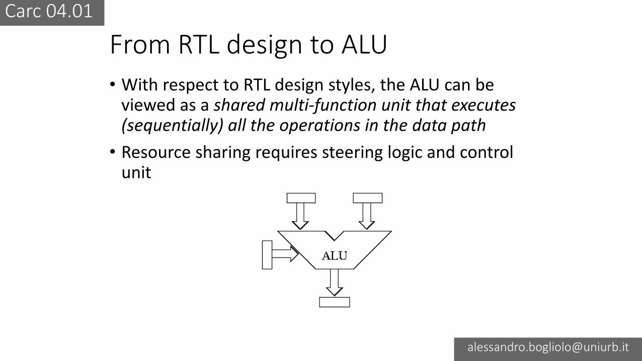
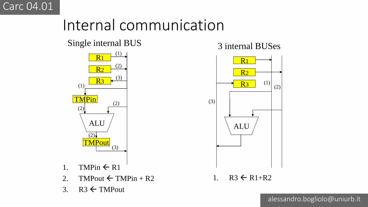
• With respect to RTL design styles, the ALU can be viewed as a shared multi-function unit that executes (sequentially) all the operations in the data path
• Resource sharing requires steering logic and control unit
Carc 04.01
Von Neumann machine• Is a machine that reads from a memory and executes
(one at the time) the instructions belonging to a finite (functionally complete) instruction set
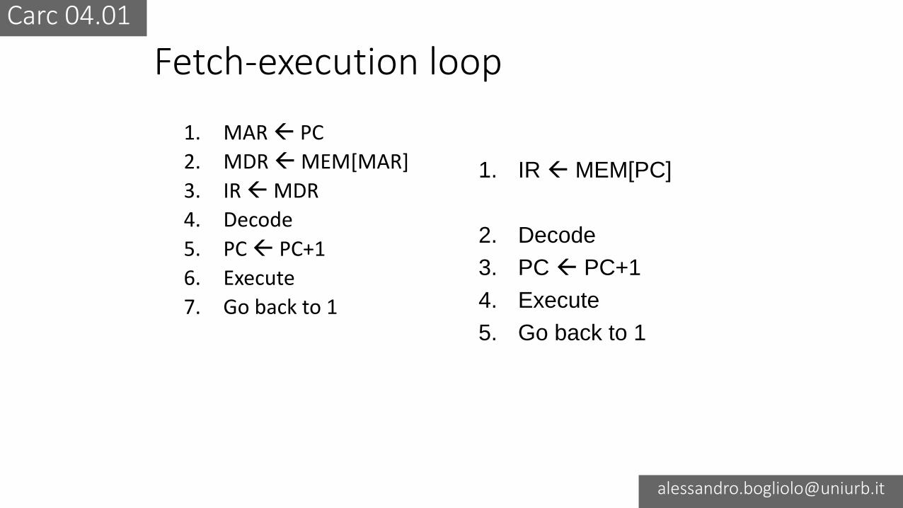
• Any data-processing task can be performed (provided that the sequence of instructions to be executed is stored in memory) by alternating two phases:• Instruction fetch
• Instruction execution
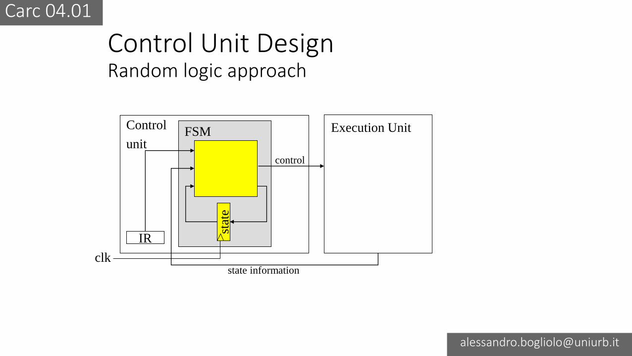
• Fetch and execution are controlled by a control unit
Carc 04.01
Von Neumann bottleneck
• The width of the communication channel between memory and CPU is much smaller than memory
• The communication channel is a bottleneck
CPU MEM
Carc 04.01
Main architectural elements
CPU MEM Input Output
Control BUSAddress BUS
Data BUS
Carc 04.01
CPU microarchitecture
ALU
R0
Rn-1
PC
MAR
MDRIR
Control
Logic
Control Unit Exec. Unit
…
CPU MEMORY
address
data
control
I/O
Carc 04.01
CPU registers
• Instruction register (IR)
• Program counter (PC)
• Memory address register (MAR)
• Memory data register (MDR)
• Generic registers R0…Rn-1
ALU
R0
Rn-1
PC
MAR
MDRIR
Control
Logic
Control Unit Exec. Unit
…
CPU
Carc 04.01
Fetch-execution loop
1. MAR PC
2. MDR MEM[MAR]
3. IR MDR
4. Decode
5. PC PC+1
6. Execute
7. Go back to 1
1. IR MEM[PC]
2. Decode
3. PC PC+1
4. Execute
5. Go back to 1
Carc 04.01
Instruction executionADD R3,R1,R2 (R3 R1+R2)
1. Operand fetchBring the operands at the inputs of ALU
2. ExecuteCompute sum
3. Write backPut the result in the destination register
Execution steps are controlled by the control unit, that
generates the control signals for registers and MUXes
Carc 04.01
Internal communication
ALU
R1
TMPout
R2
R3
TMPin
1. TMPin R1
2. TMPout TMPin + R2
3. R3 TMPout
(1)
(1)
(2)
(2)(2)
(2)
(3)
(3)
Single internal BUS
ALU
R1
R2
R3
1. R3 R1+R2
3 internal BUSes
(1)(2)
(3)
Carc 04.01
Control Unit DesignRandom logic approach
IR
Control
unit
stat
e
Execution Unit
state information
control
FSM
clk
Carc 04.01
Control Unit DesignMicroprogrammed approach
IR
Control
unit
Execution Unit
state information
control
FSM
mProg
Mem
mProg
counter
Address
selector
clk