Cardboard Machine Kit: Modules for the Rapid Prototyping of Rapid Prototyping Machines Nadya Peek MIT Center for Bits and Atoms [email protected]James Coleman A. Zahner Co. [email protected]Ilan Moyer Shaper Tools Inc. [email protected]Neil Gershenfeld MIT Center for Bits and Atoms [email protected]ABSTRACT Digital fabrication machines (such as laser cutters or 3D print- ers) can be instructed to produce any part geometry within their application space. However, machines’ application spaces are not easily modified or extended. How can we enable the pro- duction of application-specific computer-controlled machines by machine building novices? How can we facilitate rapid prototyping of rapid prototyping tools? We propose a novel set of modules, the Cardboard Machine Kit, for the construction of digital fabrication machines. These open-source modules are implemented using cardboard frames, stepper motors, and networked electronics controlled through a Python library. We evaluated the kit both through machine building workshops and by studying the usage of the kit in the wild. In the wild we observed more than 500 novice machine builders who built 125 different machines for 15 different application types. We argue that this breadth demonstrates the efficacy of this modular approach. Finally we discuss the limitations of the Cardboard Machine Kit and discuss how it could inform future machine building infrastructure. ACM Classification Keywords J.6 Computer-aided manufacturing (CAM): Computer- Aided Engineering; H.5.2 Prototyping: User Interfaces; H.5.2 User-centered Design: User Interfaces Author Keywords Digital fabrication; Machine Building; CNC; CAD/CAM; Cardboard; Prototyping INTRODUCTION Digital fabrication machines are taking a central place in HCI research and discourse on making [11]. Digital fabrication machines intended for personal use such as desktop 3D print- ers, sub-100W laser cutters, or desktop CNC milling machines are becoming more accessible through decreasing cost and increasing usability. The machines allow unlimited variation on part geometry within their application space; as long as it CHI 2017, May 6-11, 2017, Denver, CO, USA. ACM ISBN 978-1-4503-4655-9/17/05. http://dx.doi.org/10.1145/3025453.3025491 Figure 1. Machines built in the wild using the Cardboard Machine Kit: A 4-axis hot wire cutter by Fablab Monterey, an omelette ketchupping machine by Fablab Kitakagaya, a lathe by OpenDot, and a 3D scanner by Fablab Pueblo. Schematics of motion modules shown on the right. Fabrication and DIY CHI 2017, May 6–11, 2017, Denver, CO, USA 3657 This work is licensed under a Creative Commons Attribution International 4.0 License.
Transcript
Cardboard Machine Kit: Modules for the Rapid Prototypingof Rapid Prototyping Machines
Digital fabrication machines (such as laser cutters or 3D print-ers) can be instructed to produce any part geometry within theirapplication space. However, machines’ application spaces arenot easily modified or extended. How can we enable the pro-duction of application-specific computer-controlled machinesby machine building novices? How can we facilitate rapidprototyping of rapid prototyping tools? We propose a novel setof modules, the Cardboard Machine Kit, for the constructionof digital fabrication machines. These open-source modulesare implemented using cardboard frames, stepper motors, andnetworked electronics controlled through a Python library. Weevaluated the kit both through machine building workshopsand by studying the usage of the kit in the wild. In the wildwe observed more than 500 novice machine builders whobuilt 125 different machines for 15 different application types.We argue that this breadth demonstrates the efficacy of thismodular approach. Finally we discuss the limitations of theCardboard Machine Kit and discuss how it could inform futuremachine building infrastructure.
ACM Classification Keywords
J.6 Computer-aided manufacturing (CAM): Computer-Aided Engineering; H.5.2 Prototyping: User Interfaces;H.5.2 User-centered Design: User Interfaces
Author Keywords
Digital fabrication; Machine Building; CNC; CAD/CAM;Cardboard; Prototyping
INTRODUCTION
Digital fabrication machines are taking a central place in HCIresearch and discourse on making [11]. Digital fabricationmachines intended for personal use such as desktop 3D print-ers, sub-100W laser cutters, or desktop CNC milling machinesare becoming more accessible through decreasing cost andincreasing usability. The machines allow unlimited variationon part geometry within their application space; as long as it
CHI 2017, May 6-11, 2017, Denver, CO, USA.
ACM ISBN 978-1-4503-4655-9/17/05.
http://dx.doi.org/10.1145/3025453.3025491
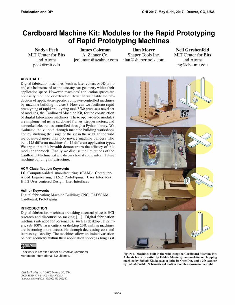
Figure 1. Machines built in the wild using the Cardboard Machine Kit:A 4-axis hot wire cutter by Fablab Monterey, an omelette ketchuppingmachine by Fablab Kitakagaya, a lathe by OpenDot, and a 3D scannerby Fablab Pueblo. Schematics of motion modules shown on the right.
Fabrication and DIY CHI 2017, May 6–11, 2017, Denver, CO, USA
3657
This work is licensed under a Creative Commons Attribution International 4.0 License.
fits within the work envelope, any line can be cut on on a lasercutter or any 3D geometry printed on a 3D printer.
However, these machines are not easily modified. It is non-trivial to extend their work envelopes or change their endeffectors. A machine often needs to be replaced entirely to ex-tend its work area. Robotic arms have interchangeable heads,but have limited work envelopes (especially with respect totheir size), comparatively low precision, complicated program-ming workflows. Adding closed-loop control to a machineor another axis to the motion platform entails remaking theircontrol electronics.
The motion systems of different digital fabrication machinesare similar. End effectors need to move in XYZ-space, andcommonly do that with 3, 4, or 5-axis control. Depending onthe application of the machine, the hardware can be optimisedfor speed, stiffness, and size. For example, a laser cutter needsto have optics that move fast, but they encounter no cuttingforce. In contrast, a milling machine used for titanium doesnot need to move quickly, but needs to be able to apply a lotof force on the workpiece. Different motors and drive trainsmight be chosen accordingly. Binding a machine to a specificapplication space makes it easier for the machine designer tooptimise the machine for that work flow. These optimisationsare important design decisions for work horse machines thatare expected to be producing parts in high volume.
However, personal digital fabrication does not need high vol-ume production. Personal fabrication is instead focused onproviding high precision tools to a very diverse set of users.These diverse users want to produce a correspondingly diverseset of products. The choices traditionally made in digital fab-rication machine design are based on assumptions of highvolume production by expert users. The resulting machinesnot well suited for possible diversity of personal fabrication.They are not easily extensible or modifiable. How can weavoid the limitations of past designs in future machines? Howcan we create machines that represent the diversity of theirusers? Can machine design be done by people who are notexperts in machine design, but are experts in their applicationspace (the machines’ users themselves)?
We present modular machine building infrastructure in theform of the Cardboard Machine Kit. This infrastructure ismeant to enable the production of digital fabrication machinesthat mirror the diversity of the goods produced on digitalfabrication machines.
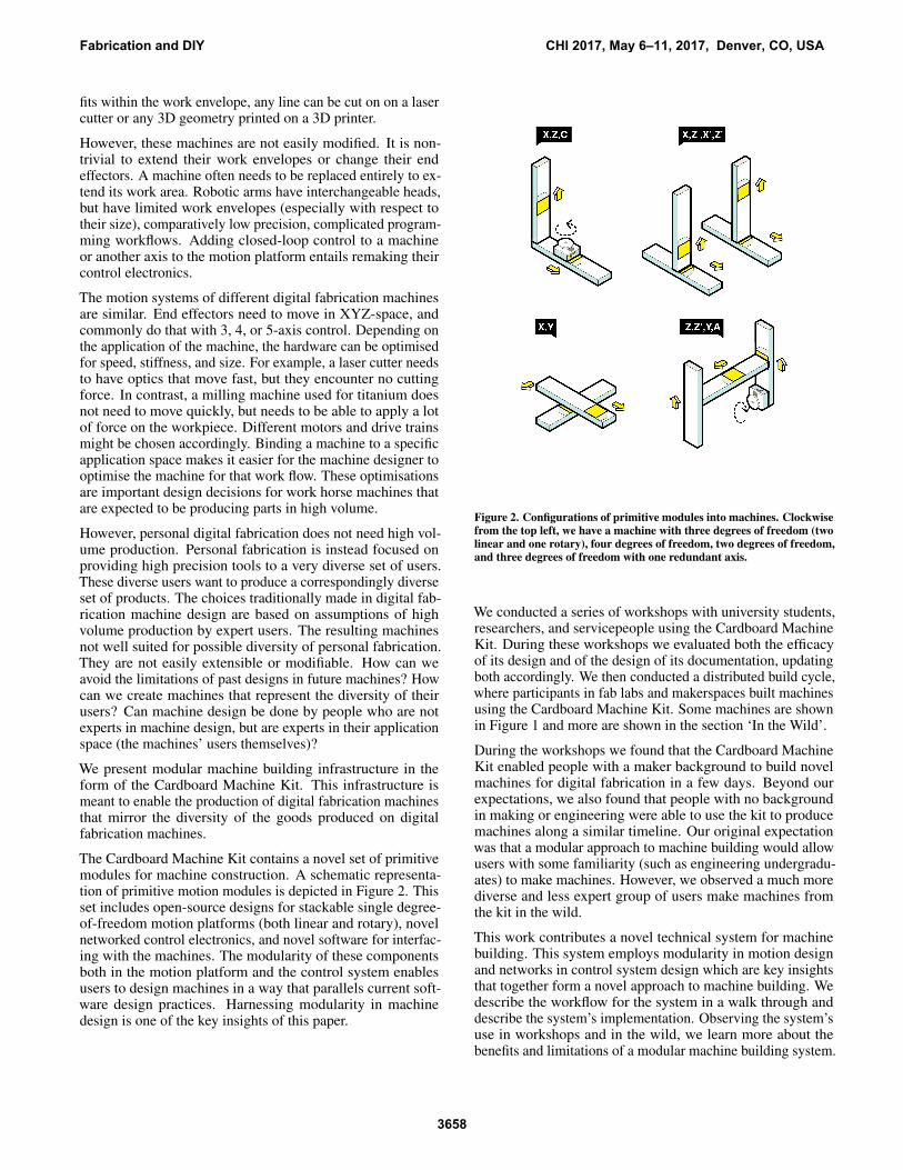
The Cardboard Machine Kit contains a novel set of primitivemodules for machine construction. A schematic representa-tion of primitive motion modules is depicted in Figure 2. Thisset includes open-source designs for stackable single degree-of-freedom motion platforms (both linear and rotary), novelnetworked control electronics, and novel software for interfac-ing with the machines. The modularity of these componentsboth in the motion platform and the control system enablesusers to design machines in a way that parallels current soft-ware design practices. Harnessing modularity in machinedesign is one of the key insights of this paper.
Figure 2. Configurations of primitive modules into machines. Clockwisefrom the top left, we have a machine with three degrees of freedom (twolinear and one rotary), four degrees of freedom, two degrees of freedom,and three degrees of freedom with one redundant axis.
We conducted a series of workshops with university students,researchers, and servicepeople using the Cardboard MachineKit. During these workshops we evaluated both the efficacyof its design and of the design of its documentation, updatingboth accordingly. We then conducted a distributed build cycle,where participants in fab labs and makerspaces built machinesusing the Cardboard Machine Kit. Some machines are shownin Figure 1 and more are shown in the section ‘In the Wild’.
During the workshops we found that the Cardboard MachineKit enabled people with a maker background to build novelmachines for digital fabrication in a few days. Beyond ourexpectations, we also found that people with no backgroundin making or engineering were able to use the kit to producemachines along a similar timeline. Our original expectationwas that a modular approach to machine building would allowusers with some familiarity (such as engineering undergradu-ates) to make machines. However, we observed a much morediverse and less expert group of users make machines fromthe kit in the wild.
This work contributes a novel technical system for machinebuilding. This system employs modularity in motion designand networks in control system design which are key insightsthat together form a novel approach to machine building. Wedescribe the workflow for the system in a walk through anddescribe the system’s implementation. Observing the system’suse in workshops and in the wild, we learn more about thebenefits and limitations of a modular machine building system.
Fabrication and DIY CHI 2017, May 6–11, 2017, Denver, CO, USA
3658
Finally we discuss how the insights from deploying the kit caninform future work in machine design.
RELATED WORK
Digital fabrication and maker culture have been increasinglypopular topics of study in the past decade. New materialsfor digital fabrication and methods for digital fabrication areregularly published [9, 25, 6, 21]. HCI research has employeddigital fabrication for making specific kinds of products [24,14, 20, 5, 7]. How DIY and maker culture is informed by andinforms ‘professional’ technology is studied in detail [3, 1].The research presented here draws from these findings, usinginsights from research on maker culture to imagine alternativeand inclusive infrastructures for digital fabrication.
The research presented here draws from the research done onearly internet infrastructure, especially End-to-end Argumentsin System Design [19], which argues for applications to beimplemented at the end points of networks.
Little Bits present a modular approach for hardware construc-tion [2] similar to the Lectron Set Braun released as an ed-ucational tool in the 1970s. We similarly use a modularconstruction-set approach, but for machine design insteadof electronics.
Mellis et al. use the term ‘untoolkit’ to refer to an extensibleframework for prototyping electronics [12]. Their approachto accessibility and breaking through the confines of the ‘kit’has influenced this work. Jacobs and Zoran study the use ofdigital fabrication tools in diverse populations [8]; we drawfrom their insights into accessibility of digital fabrication aswell.
The unconventional digital fabrication tools FreeD and ShaperTools’ Origin allow a digital model and its physical prototypeto constantly reconfigure each other [26, 16]. The implica-tions for bidirectional design integration are also explored byReForm [23]. We consider these unconventional workflowswhile drawing up the required capabilities of our machinebuilding infrastructure.
CARDBOARD MACHINE KIT
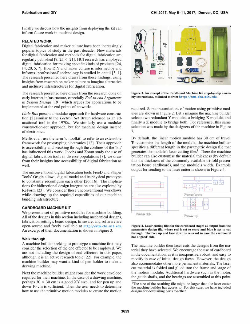
We present a set of primitive modules for machine building.All of the designs in this section including mechanical designs,fabrication settings, board design, firmware, and software areopen-source and freely available at http://mtm.cba.mit.edu.An excerpt of their documentation is shown in Figure 3.
Walk through
A machine builder seeking to prototype a machine first mayconsider the selection of the end effector to be employed. Weare not including the design of end effectors in this paper,although it is an active research topic [22]. For example, themachine builder may want a kind of pen holder to make adrawing machine.
Next the machine builder might consider the work enveloperequired for their machine. In the case of a drawing machine,perhaps 30 × 30 cm is a good XY size, and for pen up anddown 10 cm is sufficient. Then the user needs to determinehow to use the primitive motion modules to create the motion
Figure 3. An excerpt of the Cardboard Machine Kit step-by-step assem-bly instructions, as linked to from http://mtm.cba.mit.edu.
required. Some instantiations of motion using primitive mod-ules are shown in Figure 2. Let’s imagine the machine builderselects two redundant Y modules, a bridging X module, andfinally a Z module to bridge both. For reference, this sameselection was made by the designers of the machine in Figure7.
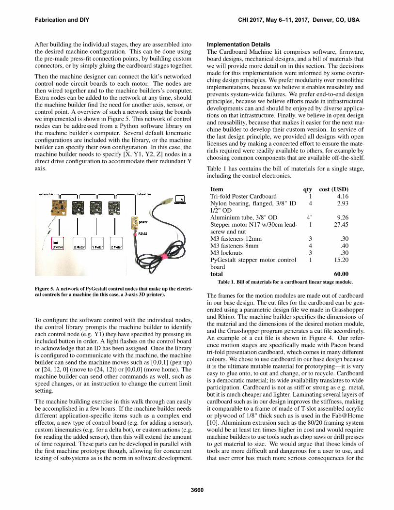
By default, the linear motion module has 30 cm of travel.To customise the length of the module, the machine builderspecifies a different length in the parametric design file thatgenerates the module’s laser cutting files1. There the machinebuilder can also customise the material thickness (by defaultthis the thickness of the commonly available tri-fold presen-tation board cardboard), and the module’s width. Exampleoutput for sending to the laser cutter is shown in Figure 4.
Figure 4. Laser cutting files for the cardboard stages as output from theparametric design file, where red is set to score and blue is set to cutthrough. The face up and face down is relevant in case the cardboardhas a ‘good’ side.
The machine builder then laser cuts the designs from the ma-terial they have selected. We encourage the use of cardboardin the documentation, as it is inexpensive, robust, and easy tomodify in case of initial design flaws. However, the designalso accommodates other more permanent materials. The lasercut material is folded and glued into the frame and stage ofthe motion module. Additional hardware such as the motor,the guide shafts, and the bearings are assembled at this point.
1The size of the resulting file might be larger than the laser cutterthe machine builder has access to. For this case, we have includeddesigns for dovetailing parts together.
Fabrication and DIY CHI 2017, May 6–11, 2017, Denver, CO, USA
After building the individual stages, they are assembled intothe desired machine configuration. This can be done usingthe pre-made press-fit connection points, by building customconnectors, or by simply gluing the cardboard stages together.
Then the machine designer can connect the kit’s networkedcontrol node circuit boards to each motor. The nodes arethen wired together and to the machine builders’s computer.Extra nodes can be added to the network at any time, shouldthe machine builder find the need for another axis, sensor, orcontrol point. A overview of such a network using the boardswe implemented is shown in Figure 5. This network of controlnodes can be addressed from a Python software library onthe machine builder’s computer. Several default kinematicconfigurations are included with the library, or the machinebuilder can specify their own configuration. In this case, themachine builder needs to specify [X, Y1, Y2, Z] nodes in adirect drive configuration to accommodate their redundant Yaxis.
Figure 5. A network of PyGestalt control nodes that make up the electri-cal controls for a machine (in this case, a 3-axis 3D printer).
To configure the software control with the individual nodes,the control library prompts the machine builder to identifyeach control node (e.g. Y1) they have specified by pressing itsincluded button in order. A light flashes on the control boardto acknowledge that an ID has been assigned. Once the libraryis configured to communicate with the machine, the machinebuilder can send the machine moves such as [0,0,1] (pen up)or [24, 12, 0] (move to (24, 12)) or [0,0,0] (move home). Themachine builder can send other commands as well, such asspeed changes, or an instruction to change the current limitsetting.
The machine building exercise in this walk through can easilybe accomplished in a few hours. If the machine builder needsdifferent application-specific items such as a complex endeffector, a new type of control board (e.g. for adding a sensor),custom kinematics (e.g. for a delta bot), or custom actions (e.g.for reading the added sensor), then this will extend the amountof time required. These parts can be developed in parallel withthe first machine prototype though, allowing for concurrenttesting of subsystems as is the norm in software development.
Implementation Details
The Cardboard Machine kit comprises software, firmware,board designs, mechanical designs, and a bill of materials thatwe will provide more detail on in this section. The decisionsmade for this implementation were informed by some overar-ching design principles. We prefer modularity over monolithicimplementations, because we believe it enables reusability andprevents system-wide failures. We prefer end-to-end designprinciples, because we believe efforts made in infrastructuraldevelopments can and should be enjoyed by diverse applica-tions on that infrastructure. Finally, we believe in open designand reusability, because that makes it easier for the next ma-chine builder to develop their custom version. In service ofthe last design principle, we provided all designs with openlicenses and by making a concerted effort to ensure the mate-rials required were readily available to others, for example bychoosing common components that are available off-the-shelf.
Table 1 has contains the bill of materials for a single stage,including the control electronics.
Table 1. Bill of materials for a cardboard linear stage module.
The frames for the motion modules are made out of cardboardin our base design. The cut files for the cardboard can be gen-erated using a parametric design file we made in Grasshopperand Rhino. The machine builder specifies the dimensions ofthe material and the dimensions of the desired motion module,and the Grasshopper program generates a cut file accordingly.An example of a cut file is shown in Figure 4. Our refer-ence motion stages are specifically made with Pacon brandtri-fold presentation cardboard, which comes in many differentcolours. We chose to use cardboard in our base design becauseit is the ultimate mutable material for prototyping—it is veryeasy to glue onto, to cut and change, or to recycle. Cardboardis a democratic material; its wide availability translates to wideparticipation. Cardboard is not as stiff or strong as e.g. metal,but it is much cheaper and lighter. Laminating several layers ofcardboard such as in our design improves the stiffness, makingit comparable to a frame of made of T-slot assembled acrylicor plywood of 1/8" thick such as is used in the Fab@Home[10]. Aluminium extrusion such as the 80/20 framing systemwould be at least ten times higher in cost and would requiremachine builders to use tools such as chop saws or drill pressesto get material to size. We would argue that those kinds oftools are more difficult and dangerous for a user to use, andthat user error has much more serious consequences for the
Fabrication and DIY CHI 2017, May 6–11, 2017, Denver, CO, USA
3660
resulting machine parts. Using a laser cutter outsources therequired precision in cuts to the machine instead of the user,making it easier to reliably produce useful parts.
The cardboard motion platform on the linear stage moduleshas four nubs in the style of Legos on the moving platform.These nubs match to hole patterns on the edges and middleof the frame. This way, one stage can easily be attached tothe moving platform of another stage. This is to facilitateassembling the stages into different machine configurations.However, machine builders can also assemble the stages usingmany other methods such as glue, fasteners, or by replacingthe moving platforms in the stages with parts that integrateinto the next stage.
The drive train is a 4-start 2mm pitch NEMA 17 stepper motorwith aluminium guide rails sitting on nylon bushings. The4-start lead screw enables fast travel (8mm/revolution) whilestill using the force of a lead screw. We had a run of custommotors with matching wear-compensating lead screw nutsmade for the workshops, but identical motors are availableoff the shelf. The standard design accommodates 30cm oftravel for the stage, but the parametric design can be modifiedto accommodate an arbitrary length of leadscrew. The motorand leadscrew are clearly overkill for the frame (the motor hasenough force to easily rip the cardboard frame apart), but werechosen to minimise number of parts on the bill of materials,as well as to provide reusable hardware for future machinedesign iterations.
The networked control nodes use the fabnet extended RS-485protocol for communication as described in [13]. The step-per motor boards we designed for the Cardboard MachineKit contain an AVR Atmega328 microcontroller and an anAllegro A4983 stepper motor driver for receiving packets andcontrolling the motors. They furthermore contain indicatorlights, a potentiometer for setting the current limiting to themotors, and a differential bus transceiver chip for commu-nication (a 75176AD). The firmware is written in C. TheCardboard Machine Kit stepper motor boards are the blackboards shown in Figure 5. Their designs and firmware areavailable at http://github.com/imoyer/086-005.
For controlling the machines, we present the PyGestalt libraryfor machine control. PyGestalt is open source and available on-line at http://github.com/nadya/pygestalt. PyGestalt allowsus to create virtual machines for controlling the physical ma-chines with. For example, if we have an XY stage that moveswith one motor controlling the X and a separate motor control-ling the Y, the virtual machine will assign X motion packets tothe X controller node and Y motion packets to the Y controllernode. If we have an XY stage that moves with some formof parallel kinematics (where both motors are used in both Xand Y positioning), then the appropriate components of themoves will be calculated by the virtual machine and assignedto the A node and B node. Conveniently this means that ifwe create an application, such as a program that generatescoordinates to send to a machine, we can still apply that toseveral different machines as long as we swap out the virtualmachine controller. The mechanical implementation detailsare separated from the user interface.
Example code for setting up the virtualMachine using H-bot kinematics with MXL pulleys for XY and a leadscrewwith 8mm of travel per rotation for Z below:
def initKinematics(self):
# drive components of h-bot.
# Inputs are A/B stepper motors,
# outputs are X/Y in machine coordinates.
self.aMotor = elements.elementChain.forward(
[elements.microstep.forward(4),
elements.stepper.forward(1.8),
elements.pulley.forward(2.03),
elements.invert.forward(False)])
self.bMotor = elements.elementChain.forward(
[elements.microstep.forward(4),
elements.stepper.forward(1.8),
elements.pulley.forward(2.03),
elements.invert.forward(False)])
self.zAxis = elements.elementChain.forward(
[elements.microstep.forward(4),
elements.stepper.forward(1.8),
elements.leadscrew.forward(8),
elements.invert.forward(True)])
xyKinematics = kinematics.hbot()
zKinematics = kinematics.direct(1)
compoundKinematics = kinematics.compound(
[xyKinematics, zKinematics])
self.stageKinematics = compoundKinematics
Using this virtualMachine object the user can send XYZcoordinates in millimeters without being concerned with theparticular implementation of the physical machine (whichpulleys, what lead screw pitch, etc.) or the machine needingto move both the A and B motors to move in X or Y. Thisintroduces a layer of modularity that enables the reuse oftoolpaths in machines with different machine implementations.A very simple example script for moving a machine ablearound is shown below:
import virtualMachine
if __name__ == ’__main__’:
# The persistence file retains which node has been
The virtualMachine could be the one implementedabove, or one with completely different paramaters. ThevirtualMachine furthermore has a set of standard functionsimplemented such as move or setCurrent. More functionscan be added by the user as required.
The Cardboard Machine kit comprises software, firmware,board designs, mechanical designs, and a bill of materials that
Fabrication and DIY CHI 2017, May 6–11, 2017, Denver, CO, USA
were described in this section. The approach of this implemen-tation is to create base infrastructure for machine building thatcan be augmented by the machine builders themselves.
Limitations
There are clear mechanical drawbacks to using modular stagesthat couple and decouple as machine tools. Such an assemblyof parts will never be as stiff as a custom-built monolithicmachine, even if they are made of materials that are morestiff than cardboard. Stiffness is required in machine tools towithstand cutting force with minimal deflection and vibrationat the tool tip. Connections between parts might be particularlysusceptible to vibration or introduce backlash. Using single-degree-of freedom modules furthermore implies the use ofserial kinematics, meaning that stages are stacked on top ofeach other. This means that the X axis needs to carry theweight of the Y axis on top of whatever machining forces themachine might encounter. This has implications for the rateat which the machine can accelerate and also how slop in thesystem might compound.
There are also limitations to using a networked approach forthe control system. The bandwidth of the network becomesthe limiting factor for communication with the machine. In ourcase, this is limited by RS-485, which within the machine com-municates at 35Mbit/s. If acceleration and deceleration curvesneed to be used at high resolution, this could become a prob-lem. For small-format milling, laser cutting, or 3D printingthough, 35Mbit/s is sufficient bandwidth to have comparableperformance to conventional machine tools.
By making machines out of modular mechanical and controlparts, we introduce more versatility through reconfiguration,more robustness by making broken parts easy to swap out,and lower cost by reducing the design cost of each individualmachine. These benefits come at the expense of not achievingthe same optimal designs as purpose-built machines.
A similar discussion was held during during the introductionof packet switching networks, which served as the foundationof later protocols like TCP/IP. Some people argued that packetswitching was a less optimal way to transmit data than dedi-cating entire connections between nodes to individual commu-nications, as in the telephone networks of the time [17]. Later,TCP/IP was developed to create an “effective technique formultiplexed utilization of existing interconnected networks"[4]. TCP/IP, built on top of packet switching networks, en-abled distributed heterogeneous networking at enormous scale.A fundamental technology change gave rise to the proliferationof many different networks across the globe.
We hope that modular infrastructure for machine building,of which we present a very simple example, will grow in itsrobustness and sophistication as it is demonstrated to be holdvalue over conventional machine building approaches.
WORKSHOPS
Using the Cardboard Machine Kit described in the previoussection, we ran four formal workshops. Workshops 1 and 2were held in a university with a mix of undergraduate andgraduate students of all majors (60 students per workshop).
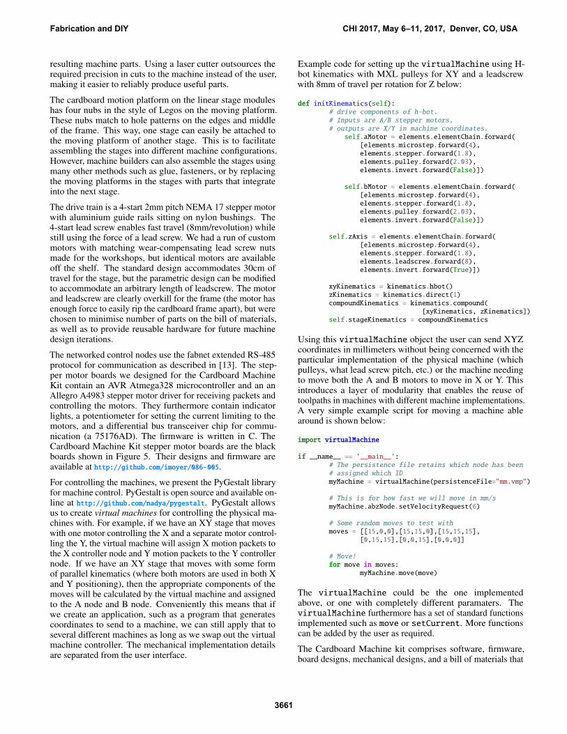
Figure 6. Workshop participants building machine parts.
During those workshops, students came to a one-hour lecture,one-hour of lab demonstration, and had eight hours of labaccess to work on their machines. Some images from thisworkshop are shown in Figure 6. Workshop 3 was held ata computer graphics conference in one four-hour slot for 30participants [15]. For Workshop 3 we pre-cut cardboard toassemble linear stages of a default length due to both timelimitations and lack of laser cutter. Finally, we taught inWorkshop 4 a series of four one and a half day workshops ona military base with servicepeople (20 students).
For all four workshops, students were provided with the fullbill of materials listed in Table 1. For Workshops 1, 2, and 4,the students additionally had access to a full digital fabricationfacility.
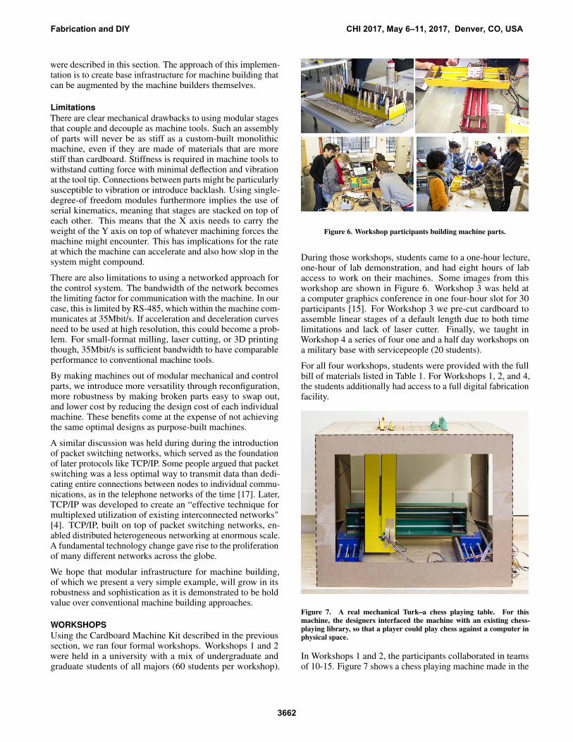
Figure 7. A real mechanical Turk–a chess playing table. For thismachine, the designers interfaced the machine with an existing chess-playing library, so that a player could play chess against a computer inphysical space.
In Workshops 1 and 2, the participants collaborated in teamsof 10-15. Figure 7 shows a chess playing machine made in the
Fabrication and DIY CHI 2017, May 6–11, 2017, Denver, CO, USA
3662
first workshop. The chess machine was one of four machinesproduced. It includes a chessboard and app for playing chesson the table remotely. The end effector in this case is a magnetwhich can move the pieces around on the table. To achieve this,the students split into groups concerned with app development,UI, table design, controls, chess piece design, and mechanicalimplementation. The end effector development quickly startedworking on the possibilities of magnetic interference betweenpieces, especially when moving the knight. Despite the fi-nal motion system not being ready, the sub team was able totest with a minimally viable prototype of the machine. Beingable to use a minimally viable prototype like this greatly con-tributed to the subteams getting everything working together,despite leaving only a few hours for system integration beforetheir final presentation.
Figure 8. A machine built that uses delta bot kinematics for mov-ing around a tongue-shaped end-effector for “subtractively decoratingcakes".
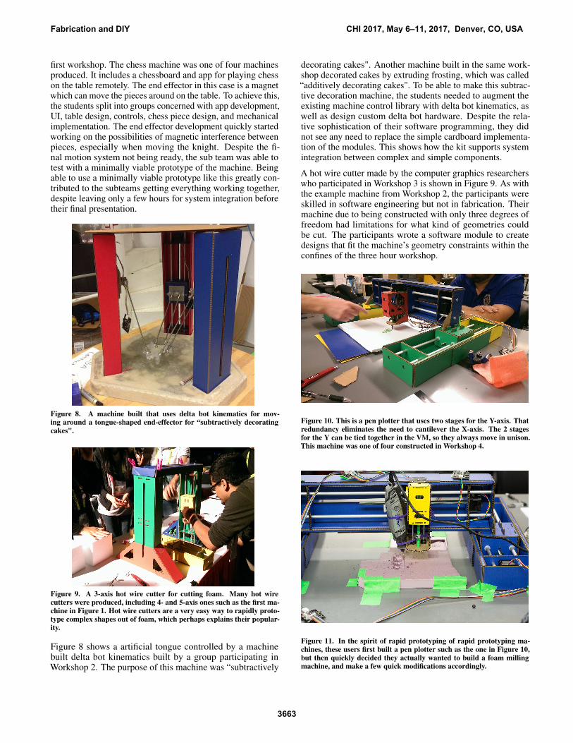
Figure 9. A 3-axis hot wire cutter for cutting foam. Many hot wirecutters were produced, including 4- and 5-axis ones such as the first ma-chine in Figure 1. Hot wire cutters are a very easy way to rapidly proto-type complex shapes out of foam, which perhaps explains their popular-ity.
Figure 8 shows a artificial tongue controlled by a machinebuilt delta bot kinematics built by a group participating inWorkshop 2. The purpose of this machine was “subtractively
decorating cakes". Another machine built in the same work-shop decorated cakes by extruding frosting, which was called“additively decorating cakes". To be able to make this subtrac-tive decoration machine, the students needed to augment theexisting machine control library with delta bot kinematics, aswell as design custom delta bot hardware. Despite the rela-tive sophistication of their software programming, they didnot see any need to replace the simple cardboard implementa-tion of the modules. This shows how the kit supports systemintegration between complex and simple components.
A hot wire cutter made by the computer graphics researcherswho participated in Workshop 3 is shown in Figure 9. As withthe example machine from Workshop 2, the participants wereskilled in software engineering but not in fabrication. Theirmachine due to being constructed with only three degrees offreedom had limitations for what kind of geometries couldbe cut. The participants wrote a software module to createdesigns that fit the machine’s geometry constraints within theconfines of the three hour workshop.
Figure 10. This is a pen plotter that uses two stages for the Y-axis. Thatredundancy eliminates the need to cantilever the X-axis. The 2 stagesfor the Y can be tied together in the VM, so they always move in unison.This machine was one of four constructed in Workshop 4.
Figure 11. In the spirit of rapid prototyping of rapid prototyping ma-chines, these users first built a pen plotter such as the one in Figure 10,but then quickly decided they actually wanted to build a foam millingmachine, and make a few quick modifications accordingly.
Fabrication and DIY CHI 2017, May 6–11, 2017, Denver, CO, USA
3663
Figures 10 and 11 are from the final workshop which wasconducted with active military servicepeople. This workshopwas part of a four part introduction to digital fabrication, wherethe first two classes taught the use of CAD and laser cutters.Many of the participants did not have college degrees. Theworkshop was 9 hours long, split over two days. For thisworkshop, the participants first constructed a pen plotter withthe modules. After the reference machine, the participantscould customise or redesign the machine.
Figure 11 shows the machine modification that was made byone of the groups in Workshop 4. Despite their limited fab-rication skills and the time limitation, they decided to turntheir pen plotter machine into a milling machine. After attach-ing the Dremel as a milling spindle, they observed that themachine was now subjected to higher force as the Dremel en-countered foam. Whereas with the pen they had only attachedthe X stage with a single cardboard tab, they now modifiedthe structure of the machine to give better load transfer andstability. This kind of modification demonstrates experientiallearning by the workshop participants. The participants ofWorkshop 4 self-reported that the machine building exercisewas “a life-changing experience". Despite their occupationsas tradespeople who service massive ships, vehicles, and othermilitary infrastructure, they reported that based on their ex-perience building machines from scratch, they now had “newsuperpowers, or the ability to understand and make any kindof machine".
IN THE WILD
Figure 12. Different types of drawing machines produced. Clockwisefrom top left, there is one made with two modules at Fablab Montreal;a Mandala Machine one made with one linear and one rotary module atFablab Reykjavik, one made with a pen hanging from pulleys at FablabHRW, and one made with three modules made of plywood at FablabTainan.
The Cardboard Machine Kit was also made available to ma-chine builders who did not participate in the formal work-shops the authors taught in person above. The kit’s full billof materials as described in Table 1 (with the exception ofthe cardboard) was sent to 64 separate maker spaces and fab
labs throughout the world. More than 10 other maker spacessourced parts for the Cardboard Machine Kit independently.
Figure 13. Many machines dealt with some aspect of food preparation.For example, clockwise from top left: a ketchup printer from FablabKitakagaya; a pancake printer from CITC Fablab Alaska; a pizza cutterfrom Fablab Barcelona; a vegetable peeler from Fablab Sendai; a cookiefroster from AS220; a chocolate printer from Fablab Trivandrum; avegetable cutter from Fablab Hamamatsu.
These machine builders were participating in a one semesterdistributed course on digital fabrication. As one of the twoweek assignments of the course, they were tasked with pro-ducing a machine. In the course they had previously learnedabout digital fabrication including laser cutting, electronicsfabrication, programming, and 3D printing. However, thereare no prerequisites for the course, and many participants werecomplete engineering novices. The participants had access tothe online documentation of the kit as well as a video lectureby the authors. They furthermore had access to the tools oftheir respective maker spaces, including a local resident expertmaker. The results presented are from two separate cohorts ofthe course.
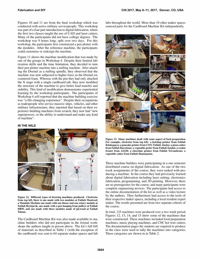
In total, 125 machines were produced over a two week period.Figures 12, 13, 14, and 15 show some of the machines thatwere constructed. These machines included food preparationmachines, music playing machines, and CNC hot wire cutters.The documentation pages the students are required to producein the class were used to tally the machines into categories.These categories are shown in in Table 2.
Fabrication and DIY CHI 2017, May 6–11, 2017, Denver, CO, USA
3664
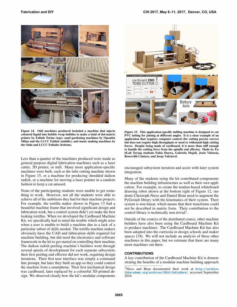
Figure 14. Odd machines produced included a machine that injectscoloured liquid into bubble wrap bubbles to make a kind of dot-matrixprinter by Fablab Torino (top); sand gardening machines by OpendotMilan and the LCCC Fablab (middle); and music making machines bythe Oulu and LCCC Fablabs (bottom).
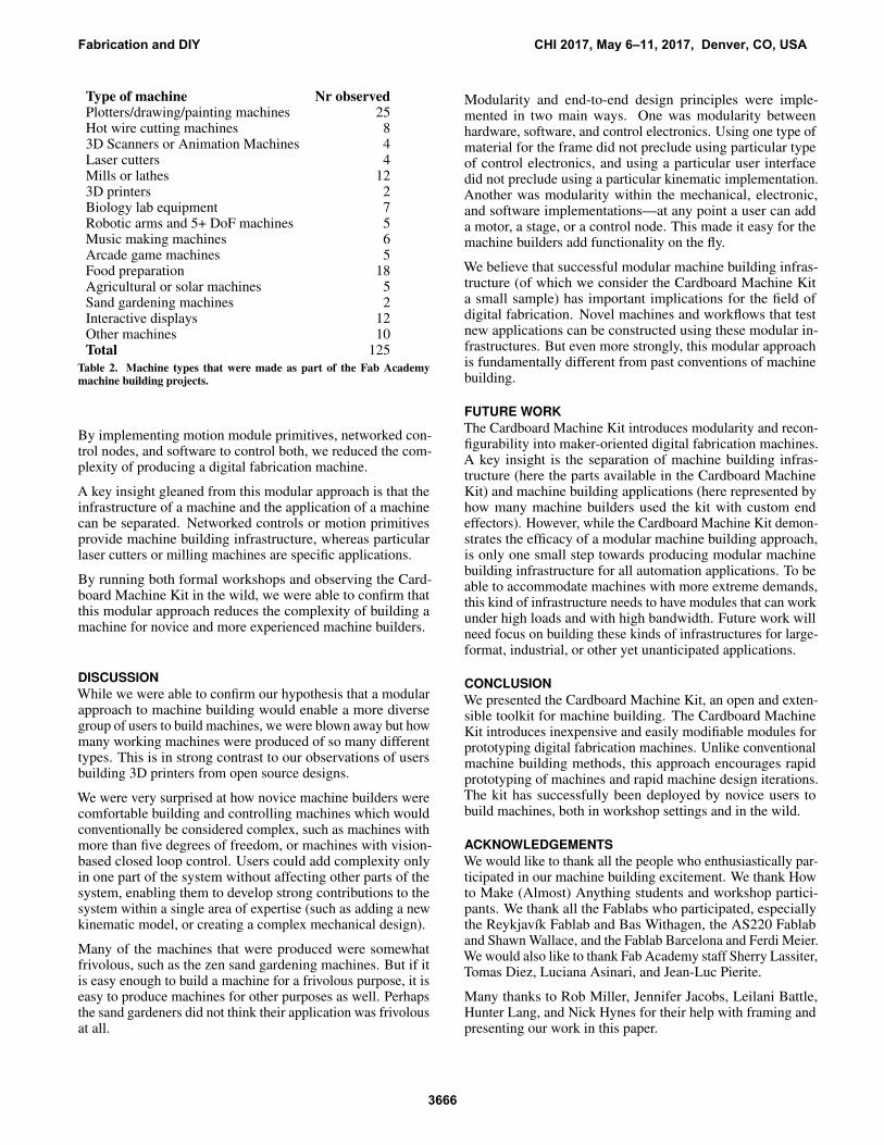
Less than a quarter of the machines produced were made asgeneral purpose digital fabrication machines such as a lasercutter, 3D printer, or mill. Many more application-specificmachines were built, such as the tube cutting machine shownin Figure 15, or a machine for producing shredded daikonradish, or a machine for moving a laser pointer in a randomfashion to keep a cat amused.
None of the participating students were unable to get some-thing to work. However, not all the students were able toachieve all of the ambitions they had for their machine projects.For example, the tortilla maker shown in Figure 13 had abeautiful machine frame that involved significant design andfabrication work, but a control system didn’t yet make the bestlooking tortillas. When we developed the Cardboard MachineKit, we specifically had in mind the trouble which might arisewhen a user is unable to build a machine due to a lack of aparticular subset of skills needed. The tortilla machine makersobviously have the CAD and fabrication skills required formachine building, but did need the electronics and softwareframework in the kit to get started on controlling their machine.The daikon radish peeling machine’s builders went throughseveral spirals of development for each separate subsystem:their first peeling end effector did not work, requiring designiterations. Their first user interface was simply a commandline prompt, but later they built an app so they could controlthe machine from a smartphone. Their first mechanical designwas cardboard, later replaced by a colourful 3D printed de-sign. We observed clearly how the kit’s modular components
Figure 15. This application-specific milling machine is designed to cutPVC tubing for joining at different angles. It is a clear example of anapplication that requires computer control (for cutting precise curves)but does not require high throughput or need to withstand high cuttingforces. Despite being made of cardboard, it is more than stiff enoughto handle the cutting force from the spindle end effector. Made by Fa-bLab Tecsup students Fabio Ibarra, Gabriela Mojoli, Jesús Valencia,Roosvelth Cántaro, and Jorge Valcárcel.
encouraged subsystem iteration and assist with later systemintegration.
Many of the students using the kit contributed componentsthe machine building infrastructure as well as their own appli-cation. For example, to create the tendon-based whiteboarddrawing robot shown at the bottom right of Figure 12, stu-dents Christoph Niess and Daniel Brun need to augment thePyGestalt library with the kinematics of their system. Theirsystem is non-linear, which means that their transforms couldnot be described in matrix form. Their contribution to thecontrol library is technically non-trivial2.
Outside of the context of the distributed course, other machinebuilders have also been using the Cardboard Machine Kitto produce machines. The Cardboard Machine Kit has alsobeen adopted into the curricula in design schools and makerspaces [18]. We will not include an analysis of these othermachines in this paper, but we estimate that there are manymore machines out there.
CONTRIBUTIONS
A key contribution of the Cardboard Machine Kit is demon-strating the benefits of a modular machine building approach.
2Niess and Brun documented their work at http://archive.fabacademy.org/archives/2016/fablabhrw/, accessed September2016.
Fabrication and DIY CHI 2017, May 6–11, 2017, Denver, CO, USA
Type of machine Nr observedPlotters/drawing/painting machines 25Hot wire cutting machines 83D Scanners or Animation Machines 4Laser cutters 4Mills or lathes 123D printers 2Biology lab equipment 7Robotic arms and 5+ DoF machines 5Music making machines 6Arcade game machines 5Food preparation 18Agricultural or solar machines 5Sand gardening machines 2Interactive displays 12Other machines 10Total 125
Table 2. Machine types that were made as part of the Fab Academymachine building projects.
By implementing motion module primitives, networked con-trol nodes, and software to control both, we reduced the com-plexity of producing a digital fabrication machine.
A key insight gleaned from this modular approach is that theinfrastructure of a machine and the application of a machinecan be separated. Networked controls or motion primitivesprovide machine building infrastructure, whereas particularlaser cutters or milling machines are specific applications.
By running both formal workshops and observing the Card-board Machine Kit in the wild, we were able to confirm thatthis modular approach reduces the complexity of building amachine for novice and more experienced machine builders.
DISCUSSION
While we were able to confirm our hypothesis that a modularapproach to machine building would enable a more diversegroup of users to build machines, we were blown away but howmany working machines were produced of so many differenttypes. This is in strong contrast to our observations of usersbuilding 3D printers from open source designs.
We were very surprised at how novice machine builders werecomfortable building and controlling machines which wouldconventionally be considered complex, such as machines withmore than five degrees of freedom, or machines with vision-based closed loop control. Users could add complexity onlyin one part of the system without affecting other parts of thesystem, enabling them to develop strong contributions to thesystem within a single area of expertise (such as adding a newkinematic model, or creating a complex mechanical design).
Many of the machines that were produced were somewhatfrivolous, such as the zen sand gardening machines. But if itis easy enough to build a machine for a frivolous purpose, it iseasy to produce machines for other purposes as well. Perhapsthe sand gardeners did not think their application was frivolousat all.
Modularity and end-to-end design principles were imple-mented in two main ways. One was modularity betweenhardware, software, and control electronics. Using one type ofmaterial for the frame did not preclude using particular typeof control electronics, and using a particular user interfacedid not preclude using a particular kinematic implementation.Another was modularity within the mechanical, electronic,and software implementations—at any point a user can adda motor, a stage, or a control node. This made it easy for themachine builders add functionality on the fly.
We believe that successful modular machine building infras-tructure (of which we consider the Cardboard Machine Kita small sample) has important implications for the field ofdigital fabrication. Novel machines and workflows that testnew applications can be constructed using these modular in-frastructures. But even more strongly, this modular approachis fundamentally different from past conventions of machinebuilding.
FUTURE WORK
The Cardboard Machine Kit introduces modularity and recon-figurability into maker-oriented digital fabrication machines.A key insight is the separation of machine building infras-tructure (here the parts available in the Cardboard MachineKit) and machine building applications (here represented byhow many machine builders used the kit with custom endeffectors). However, while the Cardboard Machine Kit demon-strates the efficacy of a modular machine building approach,is only one small step towards producing modular machinebuilding infrastructure for all automation applications. To beable to accommodate machines with more extreme demands,this kind of infrastructure needs to have modules that can workunder high loads and with high bandwidth. Future work willneed focus on building these kinds of infrastructures for large-format, industrial, or other yet unanticipated applications.
CONCLUSION
We presented the Cardboard Machine Kit, an open and exten-sible toolkit for machine building. The Cardboard MachineKit introduces inexpensive and easily modifiable modules forprototyping digital fabrication machines. Unlike conventionalmachine building methods, this approach encourages rapidprototyping of machines and rapid machine design iterations.The kit has successfully been deployed by novice users tobuild machines, both in workshop settings and in the wild.
ACKNOWLEDGEMENTS
We would like to thank all the people who enthusiastically par-ticipated in our machine building excitement. We thank Howto Make (Almost) Anything students and workshop partici-pants. We thank all the Fablabs who participated, especiallythe Reykjavík Fablab and Bas Withagen, the AS220 Fablaband Shawn Wallace, and the Fablab Barcelona and Ferdi Meier.We would also like to thank Fab Academy staff Sherry Lassiter,Tomas Diez, Luciana Asinari, and Jean-Luc Pierite.
Many thanks to Rob Miller, Jennifer Jacobs, Leilani Battle,Hunter Lang, and Nick Hynes for their help with framing andpresenting our work in this paper.
Fabrication and DIY CHI 2017, May 6–11, 2017, Denver, CO, USA
3666
REFERENCES
1. Morgan G. Ames, Jeffrey Bardzell, Shaowen Bardzell,Silvia Lindtner, David A. Mellis, and Daniela K. Rosner.2014. Making Cultures: Empowerment, Participation,and Democracy - or Not?. In CHI ’14 Extended Abstractson Human Factors in Computing Systems (CHI EA ’14).ACM, New York, NY, USA, 1087–1092. DOI:http://dx.doi.org/10.1145/2559206.2579405
2. Ayah Bdeir. 2009. Electronics As Material: LittleBits. InProceedings of the 3rd International Conference onTangible and Embedded Interaction (TEI ’09). ACM,New York, NY, USA, 397–400. DOI:http://dx.doi.org/10.1145/1517664.1517743
3. Leah Buechley, Daniela K. Rosner, Eric Paulos, andAmanda Williams. 2009. DIY for CHI: Methods,Communities, and Values of Reuse and Customization. InCHI ’09 Extended Abstracts on Human Factors inComputing Systems (CHI EA ’09). ACM, New York, NY,USA, 4823–4826. DOI:http://dx.doi.org/10.1145/1520340.1520750
4. David Clark. 1988. The design philosophy of the DARPAInternet protocols. ACM SIGCOMM ComputerCommunication Review 18, 4 (1988), 106–114.
5. Wei Gao, Yunbo Zhang, Diogo C Nazzetta, KarthikRamani, and Raymond J Cipra. 2015. RevoMaker:Enabling Multi-directional and Functionally-embedded3D printing using a Rotational Cuboidal Platform. InProceedings of the 28th Annual ACM Symposium on UserInterface Software & Technology. ACM, 437–446.
6. F. Gramazio and M. Kohler. 2014. Made by Robots:Challenging Architecture at a Larger Scale. Wiley.https://books.google.com/books?id=YUyPAwAAQBAJ
7. Scott E Hudson. 2014. Printing teddy bears: a techniquefor 3D printing of soft interactive objects. In Proceedingsof the SIGCHI Conference on Human Factors inComputing Systems. ACM, 459–468.
8. Jennifer Jacobs and Amit Zoran. 2015. Hybrid Practice inthe Kalahari: Design Collaboration Through DigitalTools and Hunter-Gatherer Craft. In Proceedings of the33rd Annual ACM Conference on Human Factors inComputing Systems (CHI ’15). ACM, New York, NY,USA, 619–628. DOI:http://dx.doi.org/10.1145/2702123.2702362
9. J. A. Lewis. 2006. Direct Ink Writing of 3D FunctionalMaterials. Advanced Functional Materials 16, 17 (2006),2193–2204. DOI:http://dx.doi.org/10.1002/adfm.200600434
11. David Mellis, Sean Follmer, Björn Hartmann, LeahBuechley, and Mark D. Gross. 2013a. FAB at CHI:Digital Fabrication Tools, Design, and Community. InCHI ’13 Extended Abstracts on Human Factors in
Computing Systems (CHI EA ’13). ACM, New York, NY,USA, 3307–3310. DOI:http://dx.doi.org/10.1145/2468356.2479673
12. David A. Mellis, Sam Jacoby, Leah Buechley, HannahPerner-Wilson, and Jie Qi. 2013b. Microcontrollers AsMaterial: Crafting Circuits with Paper, Conductive Ink,Electronic Components, and an "Untoolkit". InProceedings of the 7th International Conference onTangible, Embedded and Embodied Interaction (TEI ’13).ACM, New York, NY, USA, 83–90. DOI:http://dx.doi.org/10.1145/2460625.2460638
13. Ilan Moyer. 2013. A Gestalt Framework for VirtualMachine Control of Automated Tools. Master’s thesis.MIT, Cambridge.
14. Stefanie Mueller, Sangha Im, Serafima Gurevich,Alexander Teibrich, Lisa Pfisterer, François Guimbretière,and Patrick Baudisch. 2014. WirePrint: 3D PrintedPreviews for Fast Prototyping. In Proceedings of the 27thAnnual ACM Symposium on User Interface Software andTechnology (UIST ’14). ACM, New York, NY, USA,273–280. DOI:http://dx.doi.org/10.1145/2642918.2647359
15. Nadya Peek and James Coleman. 2015. Design Machines.In SIGGRAPH 2015: Studio (SIGGRAPH ’15). ACM,New York, NY, USA, Article 2, 1 pages. DOI:http://dx.doi.org/10.1145/2785585.2792578
16. Alec Rivers, Ilan E. Moyer, and Frédo Durand. 2012.Position-correcting Tools for 2D Digital Fabrication.ACM Trans. Graph. 31, 4, Article 88 (July 2012), 7 pages.DOI:http://dx.doi.org/10.1145/2185520.2185584
17. Lawrence G. Roberts. 1978. The evolution of packetswitching. Proc. IEEE 66, 11 (1978), 1307–1313.
18. Daniel Saakes. 2016. KAIST Cardboard Stage Metric.https://github.com/daan/cardboard-stage-metric.(2016).
19. Jerome H. Saltzer, David P. Reed, and David D. Clark.1984. End-to-end arguments in system design. ACMTransactions on Computer Systems (TOCS) 2, 4 (1984),277–288.
20. Valkyrie Savage, Andrew Head, Björn Hartmann, Dan B.Goldman, Gautham Mysore, and Wilmot Li. 2015.Lamello: Passive Acoustic Sensing for Tangible InputComponents. In Proceedings of the 33rd Annual ACMConference on Human Factors in Computing Systems(CHI ’15). ACM, New York, NY, USA, 1277–1280. DOI:http://dx.doi.org/10.1145/2702123.2702207
22. Guanyun Wang, Lining Yao, Wen Wang, Jifei Ou,Chin-Yi Cheng, and Hiroshi Ishii. 2016. xPrint: AModularized Liquid Printer for Smart MaterialsDeposition. In Proceedings of the 2016 CHI Conferenceon Human Factors in Computing Systems (CHI ’16).
Fabrication and DIY CHI 2017, May 6–11, 2017, Denver, CO, USA
ACM, New York, NY, USA, 5743–5752. DOI:http://dx.doi.org/10.1145/2858036.2858281
23. Christian Weichel, John Hardy, Jason Alexander, andHans Gellersen. 2015. ReForm: integrating physical anddigital design through bidirectional fabrication. InProceedings of the 28th Annual ACM Symposium on UserInterface Software & Technology. ACM, 93–102.
24. Karl Willis, Eric Brockmeyer, Scott Hudson, and IvanPoupyrev. 2012. Printed Optics: 3D Printing ofEmbedded Optical Elements for Interactive Devices. InProceedings of the 25th Annual ACM Symposium on UserInterface Software and Technology (UIST ’12). ACM,New York, NY, USA, 589–598. DOI:http://dx.doi.org/10.1145/2380116.2380190
25. Willie Wu, Adam DeConinck, and Jennifer A. Lewis.2011. Omnidirectional Printing of 3D MicrovascularNetworks. Advanced Materials 23, 24 (2011),H178–H183. DOI:http://dx.doi.org/10.1002/adma.201004625
26. Amit Zoran and Joseph A. Paradiso. 2013. FreeD: AFreehand Digital Sculpting Tool. In Proceedings of theSIGCHI Conference on Human Factors in ComputingSystems (CHI ’13). ACM, New York, NY, USA,2613–2616. DOI:http://dx.doi.org/10.1145/2470654.2481361
Fabrication and DIY CHI 2017, May 6–11, 2017, Denver, CO, USA