Malaysian Maritime Academy Correspondence Course Cargowork MODULE 1 -TYPES OF CARGO Brief description on types of cargoes carried onboard merchant ships are as follows: - General Cargo The modern term for these types of cargoes is breakbulk cargoes. It consists of individual items, e.g. pieces of machinery, bags, bales, and small quantities of liquids e.g. latex in deep tanks etc. Heavy items may be lifted onboard using ships gear or shore cranes. Grain Grain comprises of wheat, corn, rye, barley, oats, rice etc. Grains are liable to heat and/or sweat, especially if damp, when they may germinate or rot, therefore requiring careful pre- loading inspection, carriage and ventilation. In major grain ports, handling equipment’s are sophisticated, grain elevators being equipped to unload railway wagons, lorries, barges or coastal craft and to reload from storage silos at high speed into ocean going ships. For discharging grains, the pneumatic sucker system, evacuators and grabs may be utilised. Timber Includes timber and its by product - e.g. hardwood and softwood logs, sawn timber, wooden products, wood chips wood pulp and paper products. Where practicable, timber as it is, is carried on deck. The securing and proper stowage of deck timber has the effect of increasing a ships freeboard and because of this timber carrier may be allotted lumber loadlines in addition to the usual load lines. Timber loadlines allow ships to load more cargo as compared to the ordinary load lines as it has the following effects: a. Reserve buoyancy of vessel is increased by compact mass of buoyant timber above the freeboard deck. b. Effective freeboard is increased with beneficial effect on the range stability. c. Weather deck hatches are protected. Coal Coal is a mineralized fossil fuel widely utilised as a source of domestic and industrial power. As a sea borne product, it is always carried in bulk. It varies from soft bituminous type to hard anthracite through to manufactured coal products. Despite the carriage of coal being an established trade, it remains as a difficult and dangerous cargo to transport due to dangers of gas explosion, spontaneous combustion, ALAM/July 2002 Page 1
Transcript
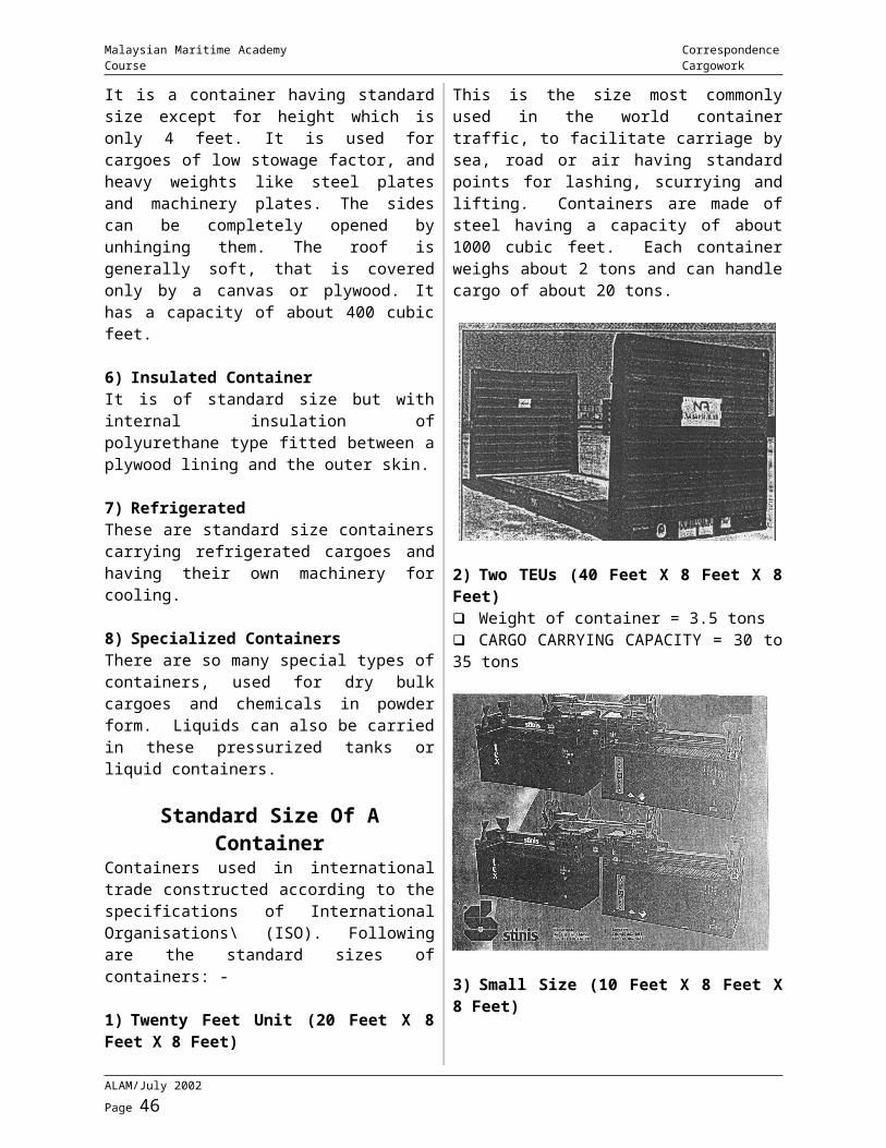
Malaysian Maritime Academy Correspondence Course Cargowork
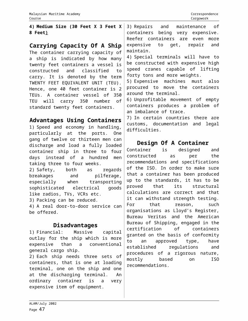
MODULE 1 -TYPES OF CARGO
Brief description on types of cargoes carried onboard merchant ships are as follows: -
General CargoThe modern term for these types of cargoes is breakbulk cargoes. It consists of individual items, e.g. pieces of machinery, bags, bales, and small quantities of liquids e.g. latex in deep tanks etc. Heavy items may be lifted onboard using ships gear or shore cranes.
GrainGrain comprises of wheat, corn, rye, barley, oats, rice etc. Grains are liable to heat and/or sweat, especially if damp, when they may germinate or rot, therefore requiring careful pre-loading inspection, carriage and ventilation. In major grain ports, handling equipment’s are sophisticated, grain elevators being equipped to unload railway wagons, lorries, barges or coastal craft and to reload from storage silos at high speed into ocean going ships. For discharging grains, the pneumatic sucker system, evacuators and grabs may be utilised.
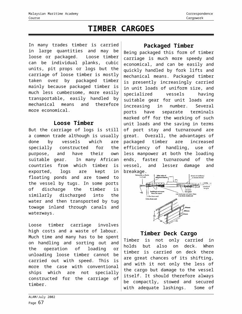
TimberIncludes timber and its by product - e.g. hardwood and softwood logs, sawn timber, wooden products, wood chips wood pulp and paper products. Where practicable, timber as it is, is carried on deck. The securing and proper stowage of deck timber has the effect of increasing a ships freeboard and because of this timber carrier may be allotted lumber loadlines in addition to the usual load lines.
Timber loadlines allow ships to load more cargo as compared to the ordinary load lines as it has the following effects:
a. Reserve buoyancy of vessel is increased by compact mass of buoyant timber above the freeboard deck.b. Effective freeboard is increased with beneficial effect on the range stability.c. Weather deck hatches are protected.
CoalCoal is a mineralized fossil fuel widely utilised as a source of domestic and industrial power. As a sea borne product, it is always carried in bulk. It varies from soft bituminous type to hard anthracite through to manufactured coal products.
Despite the carriage of coal being an established trade, it remains as a difficult and dangerous cargo to transport due to dangers of gas explosion, spontaneous combustion, and cargo shifting during passage and corrosion to ships hold.
FertiliserMay be carried in bulk, bags or liquid forms. Most fertilizers are harmless, especially in bags but a few can be explosive and/or corrosive. The IMO Dangerous goods Code should be consulted when carrying these cargoes.
CementIt may be subdivided mainly into bagged or bulk cargo in either finished cement or clinkers. It should be kept scrupulously dry so as to avoid solidifying.
It is often preferred to load bagged cement into the tweendecks of general cargo ships having the facility of reducing the height of stow which in the case of excessive tier heights in single deck ships may cause splitting of lower stowed bags. The handling of clinker is not so critical as it is normally carried in bulk; it can however be extremely dusty and is therefore subjected to shore-based anti pollution regulations.
LivestockNormally carried on the weatherdeck in tiers of specially constructed pens. Includes sheep, goats, cattle and buffaloes. On this type of trade it is not unusual for ships to carry up to 100,000 animals and thus the provision of adequate of fodder and drinking water is a major problem.
ALAM/July 2002 Page 1
Malaysian Maritime Academy Correspondence Course Cargowork
MetalsThese covers the whole range from raw base materials to metal articles e.g. steel products to scrap metal. All steel products are liable to shift at sea and need careful stowage, not only to prevent any movement, but also to avoid seriously damaging the ship.
Rust will seriously affect the value of steel products and every effort should thus be made to avoid its occurrence.
Unitised CargoAny two or more cargo joined together is said to be unitised - strapping together, pre-slinging, palletisation, containerization, etc.
Although unitisation may increase costs to some extent (extra packaging cost), it enhances cargo handling operations, reduce pilferages simplify tallying, reduce the number of people per gang. In another words it contributes greatly to a faster turn around time for the ship. Example of unitised cargo is of soft drinks packed on pallet.
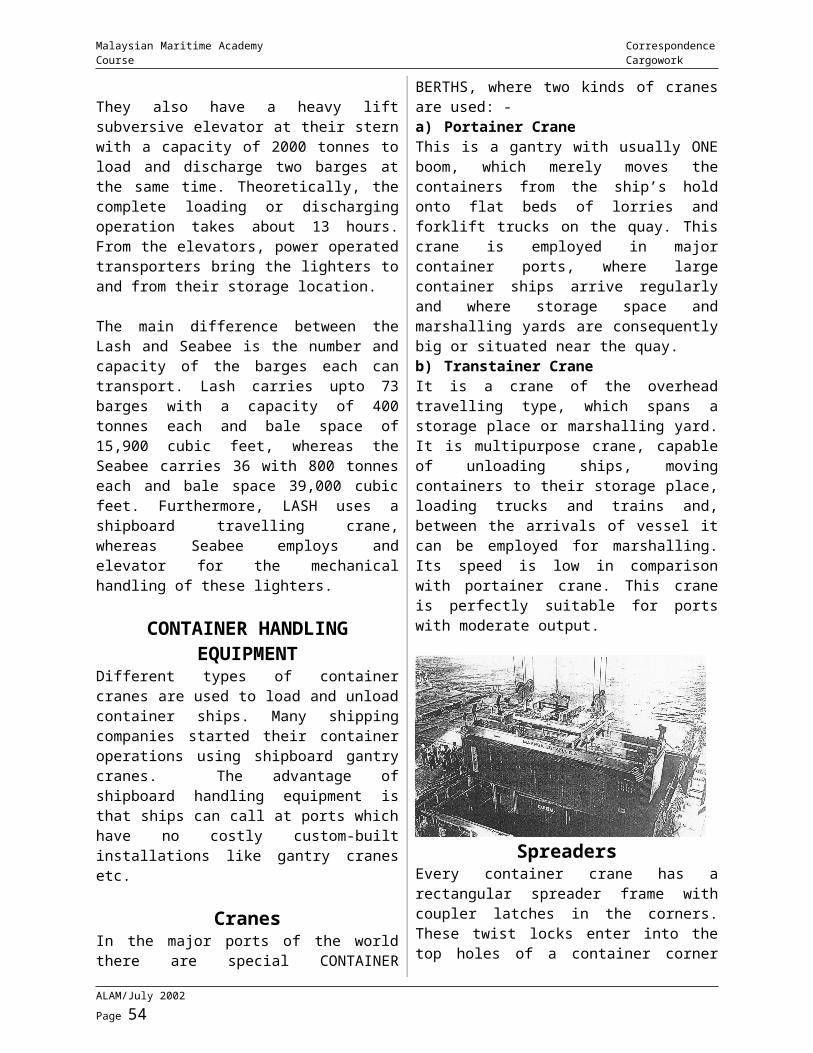
ContainersContainers are basically just a box in which cargoes are placed and the box itself is transported. Majority of general purpose containers are boxes constructed with walls of aluminium or thin steel sheeting, corrugated to provide strength and rigidity, reinforced corner posts with double watertight doors at one end. Used to carry various types of cargo e.g. tobacco, electronic components, clothing etc.
ReeferThese are mainly concerned with the carriage of fruits and vegetables and are seasonal, relying on the harvesting of crops around the world. Other reefer cargoes include frozen fruit juices, flowers and bulbs, dairy products, meat, poultry and fish, pharmaceuticals, x-ray films etc. They are handled either as a break bulk, in pallets or in containers. They require scrupulously clean and odorless cargo compartments to avoid contamination and the carriage temperature is absolutely critical.
LiquidsSea borne liquids range from drums of products such as bitumen capable of carriage in conventional tween deck ships, to parcels of edible oils transported in specially coated and heated tanks and to huge homogenous cargo of crude mineral oil carried by VLCC’s.
Most of these products are inflammable with a low flash point and many are dangerous in other ways, either emitting toxic gases or possessing corrosive qualities or both.
GasesConsists mainly of liquefied petroleum gas - LPG and liquefied natural gas - LNG. LPG consists mainly of propane and butane and are carried either under pressure at ambient temperature, fully refrigerated (-30 to 48C) or semi refrigerated under a combination of pressure and reduced temperature. Any gas that vaporises during handling and carriage will be reliquefied and circulated back to the tanks.
LNG is mainly ethane with propane and butane making up the balance. It is carried at or near its boiling point temperature of - 164C at atmospheric pressure. One of the particular features of LNG is that cargo boil off is used as fuel by the ship. However, given the high value of natural gas, the use of boil off for such purpose is becoming uneconomic and efforts are being made to reduce the daily rate of boil off to below 0.25% of cargo quantity.
Dangerous CargoUnder the auspices of IMO, a Dangerous Goods Code has evolved encompassing recommendations as to stowage, carriage, packaging, documentation and labeling of most dangerous commodities. Bulk carriers are likely to be affected by the carriage by one homogenous dangerous cargo at a time e.g. sulphur in bulk or a chemical tanker is likely to carry several lots of dangerous bulk liquids at any one time.
However, it is the general cargo ships or container ships, which can be expected to carry several classes of dangerous goods at any one time, the relative effect of which in
ALAM/July 2002 Page 2
Malaysian Maritime Academy Correspondence Course Cargowork
relation to stowage and reaction between cargoes can be somewhat complicated.
IMDG code covers carriage of dangerous goods in packaged from or in solid form in bulk.The IMDG code comes in 4 volumes plus a supplement. Another publication dealing with carriage of dangerous goods in UK is known as “Blue Book”.
NOTE - Detail description of specific cargoes will be given in the subsequent modules where appropriate.
Bale CapacityThis is the cubic capacity of a cargo compartment when the breadth is taken from the inside of the cargo battens or from the inner edges of the frames, and the height from the tank top to the lower edge of the beams and the length from inside of the bulkhead stiffeners or sparring where fitted.
Grain CapacityThis is the total internal volume of a cargo compartment measured from shell plating to shell plating and from tank top to under deck and an allowance is given for the volume occupied by frames and beams. This space is not only associated with the carriage of grain, as such, but with any form of bulk cargo, which would stow similarly, that is to say completely filling the space.
It is obvious that a solid cargo can be stowed only up to the limits of the frames and beams whereas bulk cargo will flow around such members. Therefore when measuring for general cargo, it is the bale capacity, which is taken into consideration.
Although both grain and bale capacities are normally used to show the volume or capacity of a ship to carry cargo, other units of measurement are more appropriate for specific trades, e.g. TEUs for container ships, lane-metres for Ro-Ro ships, etc.
Stowage FactorFor successful loading, a vessel must utilize every cubic meter of space to the best
advantage, with due regard to the necessary care and attention to conditions of stowage. Thus, the freight earning capability of the vessel is kept at a maximum. To do this it is necessary to know the amount of space, which each tonne of a commodity will occupy. STOWAGE FACTOR is defined as the volume in cubic meters a tonne of that cargo will occupy.
The figure does not express the actual measurement of a tonne of the cargo but takes into consideration the necessary for dunnage and the form and design of the packages.
Examples of stowage factors are: -Coal 1.18/1.33 cu.m./tonne.Maize 1.37 cu.m./tonne.Rubber in bales. 1.81/1.87 cu.m./tonne
An intelligent knowledge of the use of stowage factors is necessary to all cargo officers in order that they may make economic use of each available space unit.
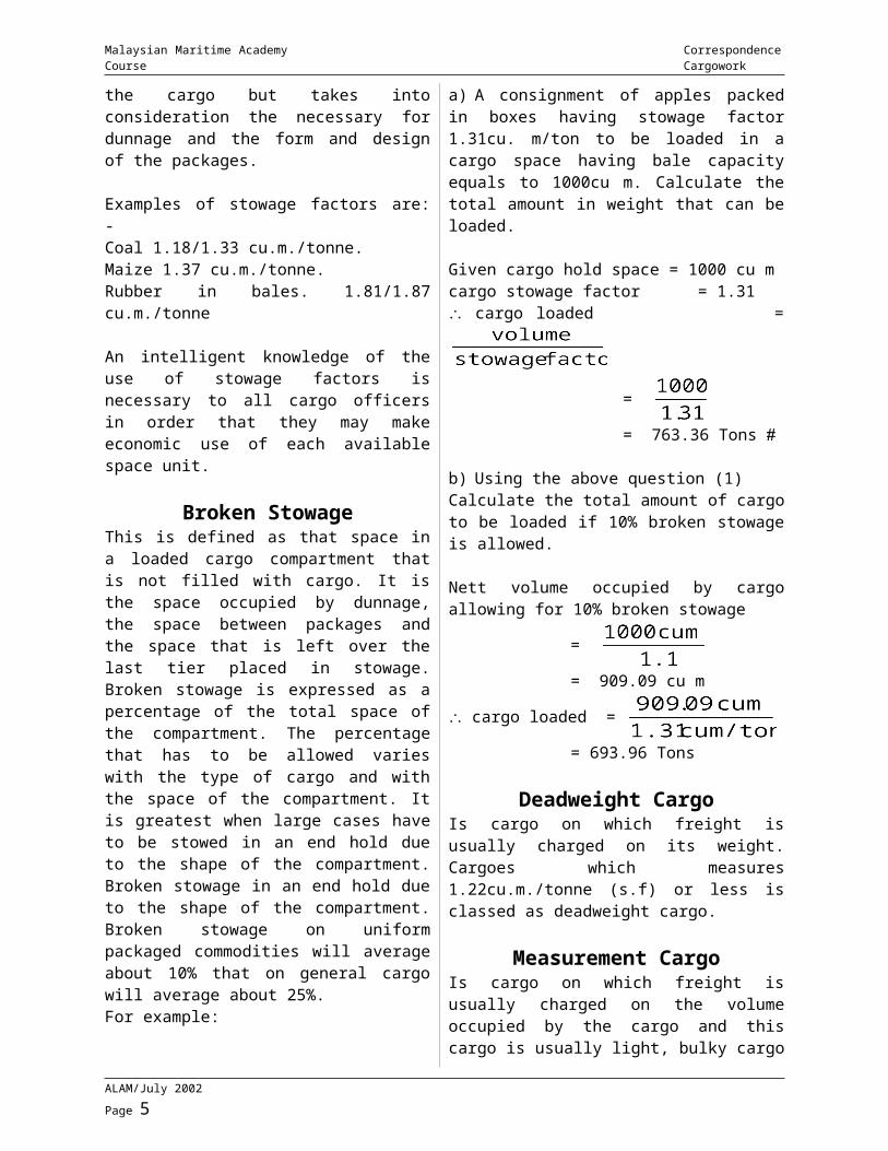
Broken StowageThis is defined as that space in a loaded cargo compartment that is not filled with cargo. It is the space occupied by dunnage, the space between packages and the space that is left over the last tier placed in stowage. Broken stowage is expressed as a percentage of the total space of the compartment. The percentage that has to be allowed varies with the type of cargo and with the space of the compartment. It is greatest when large cases have to be stowed in an end hold due to the shape of the compartment. Broken stowage in an end hold due to the shape of the compartment. Broken stowage on uniform packaged commodities will average about 10% that on general cargo will average about 25%.For example:a) A consignment of apples packed in boxes having stowage factor 1.31cu. m/ton to be loaded in a cargo space having bale capacity equals to 1000cu m. Calculate the total amount in weight that can be loaded.
Given cargo hold space = 1000 cu mcargo stowage factor = 1.31
ALAM/July 2002 Page 3
Malaysian Maritime Academy Correspondence Course Cargowork
cargo loaded =
=
= 763.36 Tons
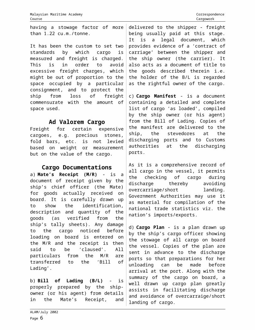
b) Using the above question (1)Calculate the total amount of cargo to be loaded if 10% broken stowage is allowed.
Nett volume occupied by cargo allowing for 10% broken stowage
=
= 909.09 cu m
cargo loaded =
= 693.96 Tons
Deadweight CargoIs cargo on which freight is usually charged on its weight. Cargoes which measures 1.22cu.m./tonne (s.f) or less is classed as deadweight cargo.
Measurement CargoIs cargo on which freight is usually charged on the volume occupied by the cargo and this cargo is usually light, bulky cargo having a stowage factor of more than 1.22 cu.m./tonne.
It has been the custom to set two standards by which cargo is measured and freight is charged. This is in order to avoid excessive freight charges, which might be out of proportion to the space occupied by a particular consignment, and to protect the ship from loss of freight commensurate with the amount of space used.
Ad Valorem CargoFreight for certain expensive cargoes, e.g. precious stones, fold bars, etc. is not levied based on weight or measurement but on the value of the cargo.
Cargo Documentationsa) Mate’s Receipt (M/R) - is a document of receipt given by the ship’s chief officer (the Mate) for goods actually received on board. It
is carefully drawn up to show the identification, description and quantity of the goods (as verified from the ship’s tally sheets). Any damage to the cargo noticed before loading on board is entered on the M/R and the receipt is then said to be ‘claused’. All particulars from the M/R are transferred to the ‘Bill of Lading’.
b) Bill of Lading (B/L) - is properly prepared by the ship-owner (or his agent) from details in the Mate’s Receipt, and delivered to the shipper - freight being usually paid at this stage. It is a legal document, which provides evidence of a ‘contract of carriage’ between the shipper and the ship owner (the carrier). It also acts as a document of title to the goods described therein i.e. the holder of the B/L is regarded as the rightful owner of the cargo.
c) Cargo Manifest - is a document containing a detailed and complete list of cargo ‘as loaded’, compiled by the ship owner (or his agent) from the Bill of Lading. Copies of the manifest are delivered to the ship, the stevedores at the discharging ports and to Customs authorities at the discharging ports.
As it is a comprehensive record of all cargo in the vessel, it permits the checking of cargo during discharge thereby avoiding overcarriage/short landing. Government Authorities may use it as material for compilation of the national trade statistics viz. the nation’s imports/exports.
d) Cargo Plan - is a plan drawn up by the ship’s cargo officer showing the stowage of all cargo on board the vessel. Copies of the plan are sent in advance to the discharge ports so that preparations for her unloading can be made before arrival at the port. Along with the summary of the cargo on board, a well drawn up cargo plan greatly assists in facilitating discharge and avoidance of overcarraige/short landing of cargo.
e) Dangerous Cargo List - a shipper is obligated to declare to the Master full details of any dangerous/hazardous cargo shipped by him and covered under the “International Maritime Dangerous Goods Code’ (the I.M.D.G. Code). The Master is required to prepare a list of all dangerous/hazardous cargo
ALAM/July 2002 Page 4
Malaysian Maritime Academy Correspondence Course Cargowork
shipped on board. It should show the correct technical name of the commodity, its ‘class’ as per the I.M.D.G. Code, its quantity and weight, position of stowage on board, port of loading and the port of discharge.
Preparation Of Hold Prior To Loading General Cargo
As temporary custodians of the cargo, it is the duty of the ship’s officers to ensure that cargo is delivered in the same condition as it was received on board. Besides ensuring that damage to cargo does not occur during handling (slinging, lifting by derricks/cranes, working forklifts etc), it is also important to prevent damage as a result of the condition of the hold itself.
1.0 Cleaning the Hold1.1 The method and amount of cleaning required will depend upon the type of cargo previously carried in the hold. Generally speaking, a hold which is ready to receive cargo should be swept clean, dry, well ventilated and free from odour of the previous cargo(es).
1.2 The hold should be cleaned prior to loading. The degree of cleanliness required will depend on the nature of the cargo to be loaded. Cargoes such as grain, sugar etc. will need a scrupulously clean hold (and usually surveyed) before loading can commence, whilst cargoes such as coal, steel etc. may not require the same level of cleanliness.
2.0 Inspecting the Hold for damages, testing bilge and fire systemsAfter cleaning the hold the following inspections/tests are normally carried out:
2.1 Inspection of the hold for internal damages - e.g. pipe guard, ladder rungs, leaking pipes, bilge sounding striker plates, leaking rivets/welding seams etc.2.2 Testing the Bilge pumping system - This is done if it has not been carried out earlier during washing of the hold etc. Particular attention is paid to ensure that the bilge suction non-return valve is working and
‘backlash’ does not occur when the bilge pump is stopped.
2.3 Checking the hold fire detection / extinguishing systems - most ships are fitted with the CO2 extinguishing system and the CO2 lines to the hold are cleared by passing compressed air. Using artificial smoke usually checks the detection system.
2.4 Checking oil/water tightness of the Double Bottom tank top and its manhole covers - this is done by pressing up the tank to a head of oil/water and checking for leaks.
3.0 Making the Hold vermin freeVermin such as rats, cockroaches, silver fish etc, in the holds, can cause extensive damage to cargo on board resulting in huge damage claims from shippers/consignees.
It is a requirement by law that every ship must be in possession of a valid Derating Certificate. The Port Medical Officer issues this certificate after fumigation by the burning of sulphur or the release of cyanide gas has been carried out. The certificate is valid for six months, after which a Derating Exemption certificate will be issued if no diseased rats or a large number of rats are found on board. The rat population may be kept to a minimum by the use of anti-coagulant bait, such as sodium fluoracetate. Cockroach bait, pesticides and insecticides may be used to exterminate cockroaches and other insects. Cleanliness is the most important factor in keeping a ship vermin free. When certain cargoes such as rice, are loaded, the holds are fumigated after loading to rid the cargo of weevils.
AssignmentPlease submit the following assignment to ALAM
1) A hold, bale capacity 2000 cu m contains, 1200 tonnes of bagged flour, (stowage factor 1.15 cu m/tonnes). Calculate the broken stowage.2) Describe a cargo hold preparation in your last ship and state the cargo loaded. State the preparation of hold prior to load general cargo.
ALAM/July 2002 Page 5
Malaysian Maritime Academy Correspondence Course Cargowork
ALAM/July 2002 Page 6
Malaysian Maritime Academy Correspondence Course Cargowork
MODULE 2 - FACTORS TO CONSIDER FOR GENERAL CARGO STOWAGE
The following must be borne in mind when loading general cargo: -
1) Cargoes should be well distributed in all hatches to increase the Port speed.2) Foodstuffs and other cargoes liable to tainting - need proper separation /segregation to avoid tainting damage.
3) Heavier cargo should be placed on deck/tank top whilst lighter cargo on top of these cargoes to prevent crushing damage.
4) It is a general rule that fragile and light packages are stowed in tween deck(s) to avoid the effects of roll and pitch of vessels.
5) Ensure packages stowed evenly (not tilting), for example near turn of bilge, end holds by the proper use of dunnage to achieve compactness of cargo stowage.
6) Light packages (cartons, etc.) stowed away from cargo hold obstructions such as - frames, deck beams, stiffeners.
7) Valuable cargo should be stowed in strong rooms or in Chief Officer’s office.
8) To avoid cargoes being crushed during slinging use proper gears like pallet, spreader.
9) Proper securing of cargoes and lashing are essential. Extra pad eyes may have to be welded to have more securing points for lashing cargoes.
Port SpeedEach day that a ship remains unnecessarily in port results in a reduction of the ship’s earning capacity. An unnecessary delay in port increase the port dues allied costs and encroaches on the time that she would have been steaming on her next voyage.
Ships officers should aim for increasing ‘port speed’ by efficient distribution of cargo, readiness of cargo spaces etc. This ‘speed of
turn round’ is also dependent on port facilities for clearing the cargo etc.
General Cargo StowageThe following points must be borne in mind when planning loading of General Cargo by Chief Mate or officer in charge of loading.a) Safety of the ship stability considerations proper trim/list/draught avoiding structural stresses avoiding physical damage from cargo
b) Safety of the crew and port workers preventing unstable cargo blocks avoiding blocking of escape routes /safety appliances protection from toxic fumes/fire hazards
c) Avoiding damage to cargo avoiding condensation/water damage protection from taint / contamination / interaction preventing physical damage to cargo preventing pilferage
d) Maximum use of available space on board minimizing ‘broken stowage using ‘filler’ cargo
e) Rapid and systematic discharging and loading providing maximum number of working hatches/even distribution preventing over stowed cargo preventing over carried/short landed cargo (proper segregation/marking). enhancing ‘port speed’
Cargo PlansA cargo plan is a plan showing the disposition and distribution of cargo throughout the vessel, in as much detail as is possible.
A cargo plan for a general cargo ship will usually be drawn up at the last port of loading from information derived from the deck officers cargo workbooks, from mates receipt and from
ALAM/July 2002 Page 7
Malaysian Maritime Academy Correspondence Course Cargowork
loading plans produced by shore personnel at the loading ports. Copies of the plan will usually be sent ahead of the ship to the discharge ports.
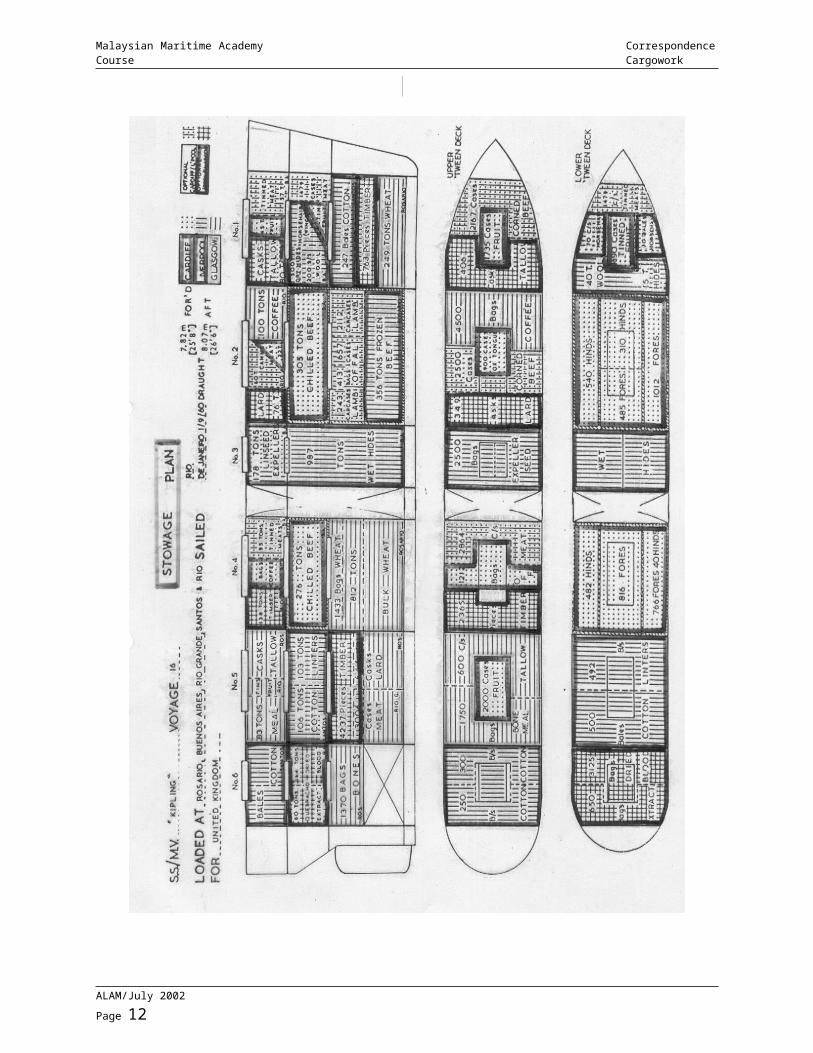
Whilst the plan is not a scale drawing, it should show with some accuracy the location of specific parcels of cargoes in the locker doors, hatchways so that the order of discharge may be planned Whilst the format of the plan will vary from company to company, most plans will show the lower holds in elevation (side view) and other compartments such as tween decks and deck lockers, in plan view. Where possible, each parcel of cargo should be identified separately, but this is not always possible when many small parcels are involved (in which case they are grouped together).
A typical entry on the plan could be as follows: - L’POOL/PNG 400 CASES CORNED BEEF “SPAR” 23t.i.e. 400 cases of corned beef, loaded at Liverpool for discharge at Penang, all cases marked “SPAR” for identification and the total weight of the parcel is 23 tones.
It is usual to colour the plan according to the port of discharge, so that the likelihood of overlooking a parcel of cargo and carrying it to the next port (i.e. overcarriage) is reduced. In the case of cargo having optional ports of discharge it is coloured in both port’s colours. Where there is unused space adjacent to stowed cargo, it is measured up, and the calculated volume measured, and entered on the plan. Various symbols and conventions may be used: - for example, parcels separated by a diagonal line on a side elevation, are side by side in the hold.
In addition to the actual drawing, other useful information is shown in the plan. The name of the ship, master’s name, the voyage number, cargo loaded ON DECK, in masthouses, and in various other extraneous places such as the mate’s office and the draft at the last loading port are shown in the cargo plan. It is good practice to append a statement of dangerous cargo on board for quick
reference. A summary of total tonnages loaded in each hold and other information regarding dead light, as fuel, stores and water; means of separation used between particular parcels and the total space remaining are also appended to the plan.
Note: The typical cargo plan of a general cargo ship is shown on the opposite page.The cargo plan has a number of functions: - it helps to avert overcarriage and short delivery. the discharge sequence can be planned in advantage. the necessary cargo handling gear can be rigged in advance. discharge time can be estimated. transport arrangement for a particular parcel of cargo can be made. proper decisions can be made on ventilation can be arranged with the aid of the cargo plan. in the event of a fire breaking out in the compartment, the cargo plan is invaluable in fighting the fire, particularly if dangerous cargoes are in the compartment. should any cargo shift while the vessel is at sea, prompt action can be taken with the aid of the plan. the plan, enables the shipowner to assess the position regarding to diverting the vessel enroute to load further parcels of cargo.
Cargo Plan On TankersLike the cargo ships, the tanker cargo plan is particularly useful when a number of diverse cargoes are to be loaded. Unlike the cargo ship, it is only necessary to show the disposition of the tanker cargoes in plan view, at one level. It is sometime the practice to overprint the comparable importance. Most of the functions of the plan are similar to that of the general cargo plan. It is particularly useful to deck officers when loading or discharging to the chief officer for planning tank cleaning and to the chief engineer for maintaining cargo temperature. The cargo plan enables a visual record to be kept of previous cargoes, which is of significant importance to the chief officer when planning the disposition of future cargoes.
ALAM/July 2002 Page 8
Malaysian Maritime Academy Correspondence Course Cargowork
ALAM/July 2002 Page 9
Malaysian Maritime Academy Correspondence Course Cargowork
DUTIES AND RESPONSIBILITIES OF CARGO OFFICERS
Cargo OfficersThe term ‘Cargo Officers’ implies the person responsible for the safe and efficient handling and stowage of cargo on board. This responsibility also includes the proper preparation of the hold prior to loading, correct supervision during the working of cargoes proper to the preservation of cargo whilst in transit and the co-operation/co-ordination with relevant port authorities whilst in port/harbour.
The Master to the senior most deck officer i.e. the Chief Officer generally delegates the responsibilities of the Cargo Officer. The 2nd and 3rd Officers, who are called the ‘Junior Cargo Officers’, assist the Chief Officer in carrying out these duties.
Duties And ResponsibilitiesThe main duties and responsibilities of the Cargo Officer are listed below:1) To ensure the proper preparation of all cargo spaces for the types of cargo to be carried.
2) To inspect the ship’s cargo gear to ensure that it is in good working condition and in accordance with the statutory requirements.
3) To ensure that all holds, accesses and parts of the ship comply with the requirements of the Dock Safety Regulations.
4) To ensure proper status of guardrails, manhole covers, side ports, stern doors, container fittings etc.
5) To plan and supervise the proper stowage of cargo on board ensuring the safety of life and property, and avoiding excessive ship stresses whilst having adequate stability during loading and discharging and at all stages of the voyage.6) To achieve proper stowage of cargo not in such a manner as to prevent correct and speedy discharge, taking into account the
proper rotation of ports and also ensure that no cargo is over stowed.
7) To undertake measures to prevent the out-break of fire on board and to ensure that fire fighting equipment is in readiness all the time.
8) To ensure the safe operation of all ship’s cargo handling gears.
9) To avoid damage to the cargo - to ensure the proper handling, slinging, discharging, separation, ventilation, slinging, distribution of cargo. In the case of refrigerated cargoes - The proper control of temperature.
10) To take adequate measures to prevent the pilferage of cargo.
11) To maintain a daily check and record of cargo loaded or discharged including the vessel’s draught.
12) To make proper and correct entries into the Mate’s Log Book, issue relevant Mate’s Receipts for cargo loaded, drawing up of cargo plans, hatch lists, cargo summaries, dangerous cargo lists etc. To maintain the Dangerous Cargo Register.
13) To attempt a good distribution of cargo at loading and discharge ports, so as to obtain the fastest turn round of the vessel and minimise port stay.
14) To ensure that all cargo is properly secured, hatches well battened down and cargo gears secured before the vessel proceeds to sea.
15) To ensures that proper ventilation of cargo spaces is carried out to prevent cargo damage due to condensation/sweat. To check and record temperatures and CO2 concentrations in refrigerated cargo spaces.
16) In the event of bad or adverse weather conditions, to ensure the water tightness of
ALAM/July 2002 Page 10
Malaysian Maritime Academy Correspondence Course Cargowork
compartments, proper trimming of ventilators and the lashings of cargo etc.
17) To ensure that all work on board is carried out in accordance with the “Code of Safe Working Practices”.
18) To properly delegate duties to Junior Cargo Officers with adequate instructions for the proper loading/discharging and stowage of cargo and the overall safety of the vessel.
Packaging Of General CargoGeneral cargo may be presented for shipment with various forms of packaging, such as: Bags - made from natural fibres like jute/cotton or from synthetic fibres and paper. Used for cement, grain, sugar etc. They are liable to bursting at their seams. Cartons - made from cardboard. Used for finished goods like condensed milk, shoes, or for carrying fruits etc. They are very fragile and liable to be crushed. Chests - rectangular/square boxes made from plywood. Used for carrying tea. They are fragile and liable to be crushed. Cases - rectangular boxes made from wooden planks nailed and banded. Can be strong or fragile depending on quality of wood & construction of case. Used for heavier goods like spare parts etc. or to protect fragile goods. Crates - rectangular, made from wooden planks with ‘grated’ design. Not as strong as cases and sides are fragile. Used for machinery parts etc. Bales - formed when commodities such as natural fibre, cloth etc. are pressed tightly into a rectangular bundle and then strapped firmly with metal bands or cord. Lifting by hooking onto bands should be avoided. Barrels - made from shaped wooden planks called ‘staves’ and held by metal hoops. The weakest part is the rounded middle called the ‘bilge’ and the strongest is at the quarter hoop’. The opening for filling the contents is called the ‘bung’. Ideally placed on wedges, called ‘quoins’ placed below the quarter hoops keeping the ‘bilge off the
ground and the ‘bung’ upwards (i.e. ‘Bung up and bilge free’). Used for carriage of wine etc. and similar produce.
Slinging Of General CargoesLoading and discharging of cargo is facilitated by the use of proper cargo handling gears namely, derricks/cranes (the lifting machines) and slings. Slings facilitate the ‘grouping’ of unit packages of cargo conveniently for connecting to derricks / cranes. Various types of slings, for use with different types of general cargo, are available and are designed to minimise damage to the cargo during the lifting process.
Some of the principle types of slings, available are clearly explained in various textbook.
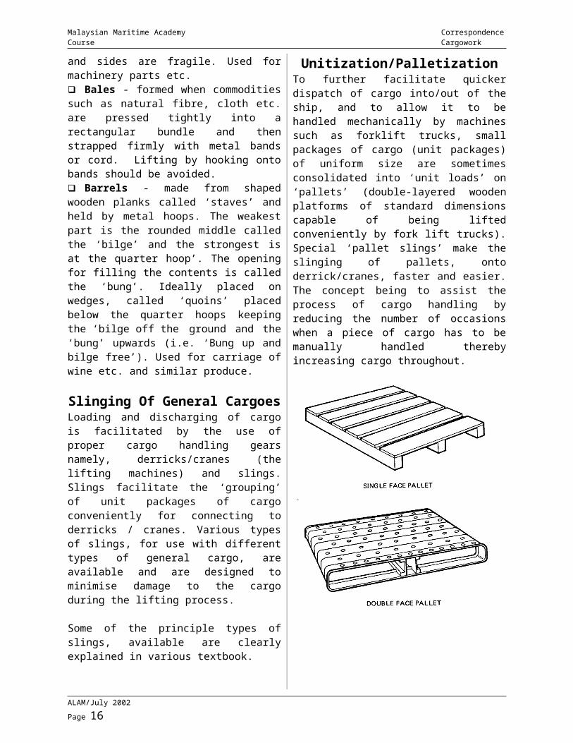
Unitization/PalletizationTo further facilitate quicker dispatch of cargo into/out of the ship, and to allow it to be handled mechanically by machines such as forklift trucks, small packages of cargo (unit packages) of uniform size are sometimes consolidated into ‘unit loads’ on ‘pallets’ (double-layered wooden platforms of standard dimensions capable of being lifted conveniently by fork lift trucks). Special ‘pallet slings’ make the slinging of pallets, onto derrick/cranes, faster and easier. The concept being to assist the process of cargo handling by reducing the number of occasions when a piece of cargo has to be manually handled thereby increasing cargo throughout.
ALAM/July 2002 Page 11
Malaysian Maritime Academy Correspondence Course Cargowork
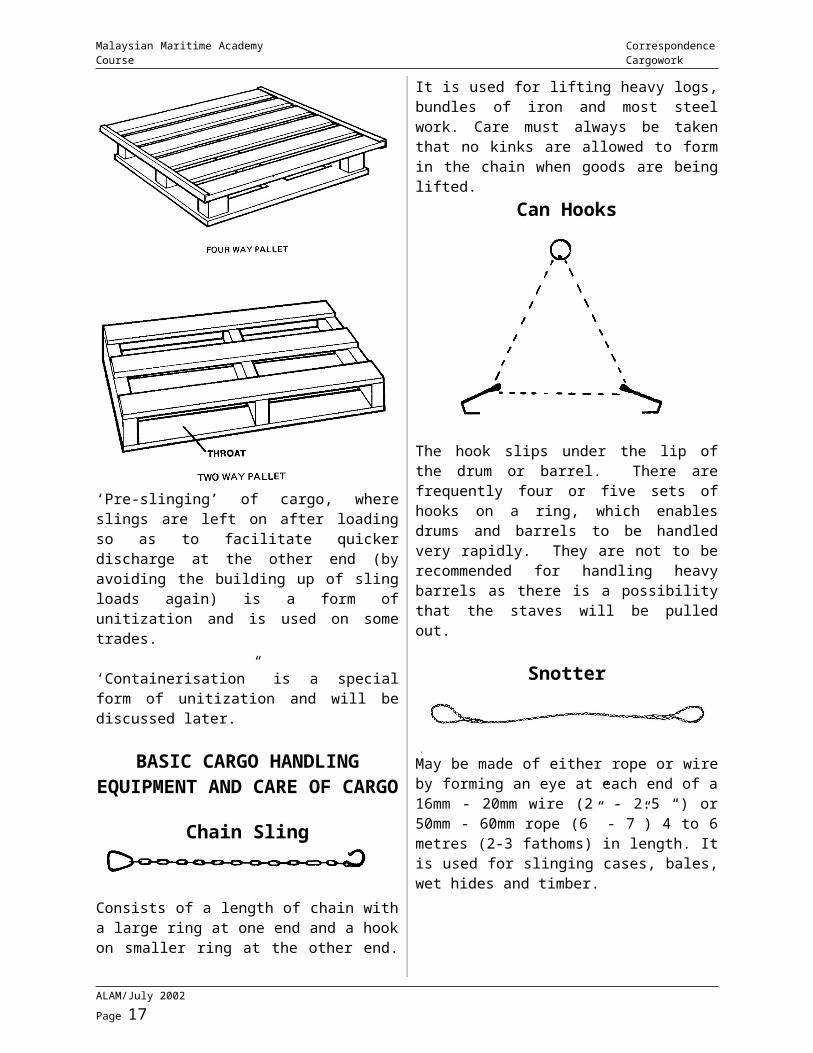
‘Pre-slinging’ of cargo, where slings are left on after loading so as to facilitate quicker discharge at the other end (by avoiding the building up of sling loads again) is a form of unitization and is used on some trades.
‘Containerisation” is a special form of unitization and will be discussed later.
BASIC CARGO HANDLINGEQUIPMENT AND CARE OF
CARGO
Chain Sling
Consists of a length of chain with a large ring at one end and a hook on smaller ring at the other end. It is used for lifting heavy logs, bundles of iron and most steel work. Care must always be taken that no kinks are allowed to form in the chain when goods are being lifted.
Can Hooks
The hook slips under the lip of the drum or barrel. There are frequently four or five sets of hooks on a ring, which enables drums and barrels to be handled very rapidly. They are not to be recommended for handling heavy barrels as there is a possibility that the staves will be pulled out.
Snotter
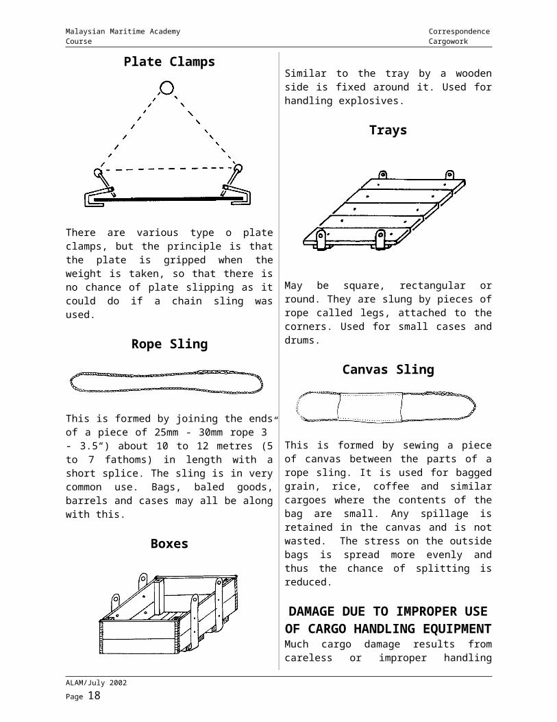
May be made of either rope or wire by forming an eye at each end of a 16mm - 20mm wire (2” - 2.5 “) or 50mm - 60mm rope (6” - 7”) 4 to 6 metres (2-3 fathoms) in length. It is used for slinging cases, bales, wet hides and timber.
Plate Clamps
There are various type o plate clamps, but the principle is that the plate is gripped when the weight is taken, so that there is no chance of plate slipping as it could do if a chain sling was used.
ALAM/July 2002 Page 12
Malaysian Maritime Academy Correspondence Course Cargowork
Rope Sling
This is formed by joining the ends of a piece of 25mm - 30mm rope 3” - 3.5“) about 10 to 12 metres (5 to 7 fathoms) in length with a short splice. The sling is in very common use. Bags, baled goods, barrels and cases may all be along with this.
Boxes
Similar to the tray by a wooden side is fixed around it. Used for handling explosives.
Trays
May be square, rectangular or round. They are slung by pieces of rope called legs, attached to the corners. Used for small cases and drums.
Canvas Sling
This is formed by sewing a piece of canvas between the parts of a rope sling. It is used for bagged grain, rice, coffee and similar cargoes where the contents of the bag are small. Any spillage is retained in the canvas and is not wasted. The stress on the outside bags is spread more evenly and thus the chance of splitting is reduced.
DAMAGE DUE TO IMPROPER USE OF CARGO HANDLING
EQUIPMENTMuch cargo damage results from careless or improper handling during the loading and discharging processes, the following being the principal sources of such damage: -
Careless Winch WorkLowering heavy slings or drafts of cargo too fast on to cargo already in stowage not infrequently is responsible for damage which, often goes undetected until discharge.
Cargo HooksThe use of these implements is indispensable in the handling of a large variety of commodities, but with bag cargo, fine bale goods, hides, fire rolls of paper and matting, etc., light packages, liquid containers, crates and like packages whose contents are exposed or unprotected, the use of cargo hooks should be strictly prohibited.
Crow and Pinch BarsThese also are indispensable to the sound stowage of many classes of heavy packages, but their use should never be permitted when stowing barrels, or other liquid containers, or with any packages which are not substantial enough to withstand damage from their use.
Crushing against Ship’s Sides
Hatch coamings, beam sockets, etc., should be safeguarded against by the use of overside skids, the correct plumbing and guying of derricks, and careful winch driving, especially when swinging booms are in use.
ALAM/July 2002 Page 13
Malaysian Maritime Academy Correspondence Course Cargowork
Dragging CargoDragging Cargo by winches along the deck to save trucking, from remote ends and wings of holds and ‘tween decks instead of making up the “draft” or “sling” near the hatch, is a prolific source of damage to, and loss of contents of the lighter class of packages, as well as to the cargo in stowage over which such is dragged.
Dropping PackagesDropping packages from trays, trucks, railway cars, top tiers of lighters, etc., by which their contents are broken or exposed, the packages splintered, deformed or loosened in their fastenings and rendered unfit for the subsequent handling they are subjected to. To avoid this, suitable skids should be used for packages, which are too heavy to be handed down.
Improper AppliancesThe use of special appliances tends to be expeditious and economical in handling of cargo, but damage is frequently caused by the improper use of such appliances.
Net slings are most useful with many kinds of small packages, but if used with bagstuff, light cases, etc., a great deal of damage results. Similarly chain slings are indispensable for certain types of packages and useful for most classes of iron goods, but the use of such with light cases, sheet iron, coils of lead or copper piping, sawn logs of valuable timber and other goods liable to buckling, fraying or marking by chain is productive of damage and claims.
Canvas or web slings should be used for slinging bag flour, coffee and like cargo, while the use of trays for certain classes of goods is much to be preferred to slinging by net or rope.
Improper SlingingToo much weight in a draft endangers the safety of packages situated at the outside edge of bottom and top tiers into which the sling is liable to be drawn by weight below and compression above.
A draft composed of many packages should taper off on top to prevent springing or
crushing the outside upper packages by compression of the sling. Light or fragile packages should not be slung along with heavy packages.
Lack of Walking BoardsLack of Walking Boards and landing platforms. Where these are not provided and used, damage is caused to packages, in towage, over which other cargo has to be worked into the position where it is to be stowed.
Packages, which are damaged after they are at “ship’s risk”, should be carefully re-coopered or repaired before stowing away.
SWEAT AND VENTILATION
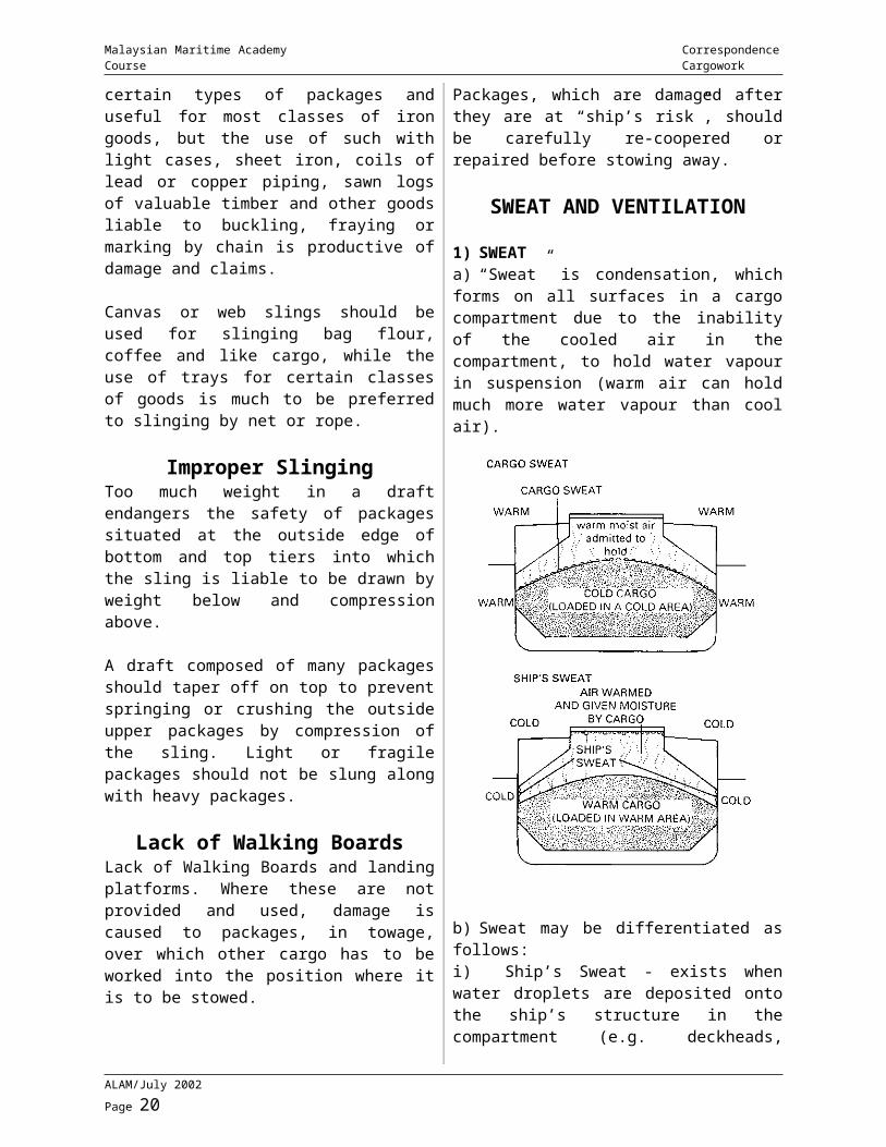
1) SWEATa) “Sweat” is condensation, which forms on all surfaces in a cargo compartment due to the inability of the cooled air in the compartment, to hold water vapour in suspension (warm air can hold much more water vapour than cool air).
b) Sweat may be differentiated as follows:
ALAM/July 2002 Page 14
Malaysian Maritime Academy Correspondence Course Cargowork
i) Ship’s Sweat - exists when water droplets are deposited onto the ship’s structure in the compartment (e.g. deckheads, beams, frames, shipside, stringers etc.) and then fall onto or come in contact with the cargo.
It occurs when the dew point of the air in the cargo compartment is more than the temperature of the outside air/structural parts of the compartment.
It is usually found on voyages from warm places to colder places.
ii) Cargo Sweat - arises when condensation forms directly on the body of cargo itself.
It occurs when the temperature of the air in the compartment (or the cargo itself) is lower than the dew point of the incoming air.
It is likely to be found on voyages from cold to warmer places.
c) Prevention of Damage by SweatAlthough intelligent use of dunnage can minimise damage from sweat, it is more prudent to consider the prevention of damage by the elimination/minimisation of sweat by efficient ventilation.
The controlling factor for the formation sweat is the relationship between the temperature and humidity of the air in/outside the compartment. Air having 100% humidity is said to be “saturated the temperature at which this occurs is called its dew point.
i) When the dew point of the outside air is lower than or equal to the dew point of the air in the compartment - VENTILATE.ii) When the dew point of the outside air is greater than the dew point of the air in the compartment - DO NOT VENTILATE.
2) VENTILATIONa) Ventilation has the main objectives of: preventing moisture damage to cargo originating from condensation (sweat) within the cargo compartment.
removing fumes and odours emanating from cargoes stowed in the compartment to prevent ‘taint’ or other damage. thus preventing fire.
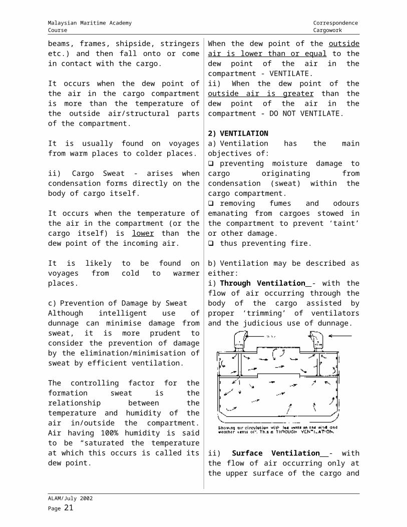
b) Ventilation may be described as either:i) Through Ventilation - with the flow of air occurring through the body of the cargo assisted by proper ‘trimming’ of ventilators and the judicious use of dunnage.
ii) Surface Ventilation - with the flow of air occurring only at the upper surface of the cargo and not being forced into the body of the cargo.
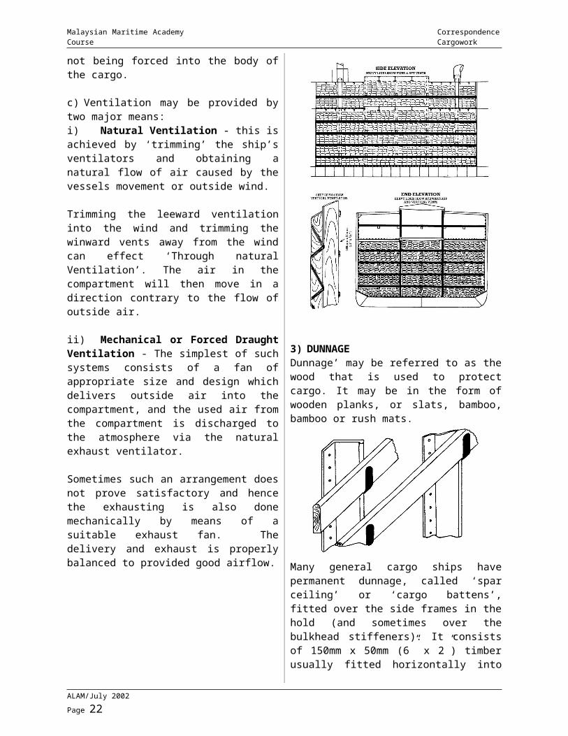
c) Ventilation may be provided by two major means:i) Natural Ventilation - this is achieved by ‘trimming’ the ship’s ventilators and obtaining a natural flow of air caused by the vessels movement or outside wind.
Trimming the leeward ventilation into the wind and trimming the winward vents away from the wind can effect ‘Through natural Ventilation’. The air in the compartment will then move in a direction contrary to the flow of outside air.
ii) Mechanical or Forced Draught Ventilation - The simplest of such systems consists of a fan of appropriate size and design which delivers outside air into the compartment, and the used air from the compartment is discharged to the atmosphere via the natural exhaust ventilator.
Sometimes such an arrangement does not prove satisfactory and hence the exhausting is also done mechanically by means of a suitable
ALAM/July 2002 Page 15
Malaysian Maritime Academy Correspondence Course Cargowork
exhaust fan. The delivery and exhaust is properly balanced to provided good airflow.
3) DUNNAGEDunnage’ may be referred to as the wood that is used to protect cargo. It may be in the form of wooden planks, or slats, bamboo, bamboo or rush mats.
Many general cargo ships have permanent dunnage, called ‘spar ceiling’ or ‘cargo battens’, fitted over the side frames in the hold (and sometimes over the bulkhead stiffeners). It consists of 150mm x 50mm (6” x 2”) timber usually fitted horizontally into cleats over the side frames with the distance between the ‘battens’ of about 230mm (9”).
Cargo battens are sometimes fitted vertically and in such cases the initial expense is generally greater. However there tends to be less subsequent damage to the battens and better protection is afforded to the cargo.
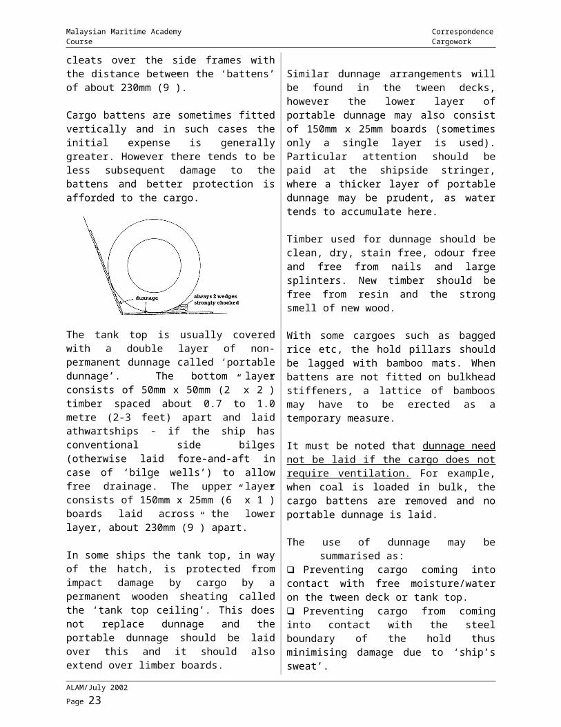
The tank top is usually covered with a double layer of non-permanent dunnage called ‘portable dunnage’. The bottom layer consists of 50mm x 50mm (2” x 2”) timber spaced about 0.7 to 1.0 metre (2-3 feet) apart and laid athwartships - if the ship has conventional side bilges (otherwise laid fore-and-aft in case of ‘bilge wells’) to allow free drainage. The upper layer consists of 150mm x 25mm (6” x 1”) boards laid across the lower layer, about 230mm (9”) apart.
In some ships the tank top, in way of the hatch, is protected from impact damage by cargo by a permanent wooden sheating called the ‘tank top ceiling’. This does not replace dunnage and the portable dunnage should be laid over this and it should also extend over limber boards.
Similar dunnage arrangements will be found in the tween decks, however the lower layer of portable dunnage may also consist of 150mm x 25mm boards (sometimes only a single layer is used). Particular attention should be paid at the shipside stringer, where a thicker layer of portable dunnage may be prudent, as water tends to accumulate here.
Timber used for dunnage should be clean, dry, stain free, odour free and free from nails and large splinters. New timber should be free from resin and the strong smell of new wood.
With some cargoes such as bagged rice etc, the hold pillars should be lagged with bamboo mats. When battens are not fitted on bulkhead
ALAM/July 2002 Page 16
Malaysian Maritime Academy Correspondence Course Cargowork
stiffeners, a lattice of bamboos may have to be erected as a temporary measure.
It must be noted that dunnage need not be laid if the cargo does not require ventilation. For example, when coal is loaded in bulk, the cargo battens are removed and no portable dunnage is laid.
The use of dunnage may be summarised as: Preventing cargo coming into contact with free moisture/water on the tween deck or tank top. Preventing cargo from coming into contact with the steel boundary of the hold thus minimising damage due to ‘ship’s sweat’. Assisting in providing ventilation, thus preventing / reducing ‘sweat’. Preventing spontaneous heating by affording good ventilation. Aiding distribution of weight over a layer of cargo thus minimising crushing damage to cargo. Preventing chafage between cargoes. Certain types can prevent pilferage of cargo. Aiding in distribution of cargo weight over tank top etc. Can be used to separate cargoes (this is not considered as a normal practice).
Entry Into Enclosed SpacesThere are many enclosed spaces on a ship - if in doubt about any space you may have to enter CHECK FIRST with Chief Officer.
An Enclosed Space Is any space or compartment that has been closed or unventilated for some time. any space or compartment that may, because of the cargo carried, contain noxious, flammable or harmful gases. any space or compartment which may be contaminated by cargo or gases leaking through a bulkhead or pipeline. any storeroom or space containing noxious or harmful materials any space or compartment which may be deficient in oxygen.These definitions include pump rooms on tankers. There may be special instructions for
routine entry into pump rooms on your ship. Make sure you know what they are.
AN ENCLOSED SPACE SHOULD NEVER BE ENTERED UNLESS
AUTHORITY HAS BEEN GIVEN BY THE MASTER OR A RESPONSIBLE
OFFICER
The atmosphere in any enclosed space may be incapable of supporting human life. It may contain flammable or toxic gases or not enough oxygen.
This is why it is essential that the Master or officer in charge, who will ensure that all the necessary safety precautions have been taken before anyone is allowed to enter an enclosed space, must give instructions or permission.
Precautions Before Entering Tanks Or Confined Spaces
1) Prior to entry into enclosed space it is essential to obtain permission first.2) Test on tank atmosphere - should be checked by using explosimeter and oxygen analyser where appropriate for safe entry.3) Ventilate space prior to entry and continuously during the operation so as to ensure the environment is safe.4) Entry should be restricted to the minimum number of personnel required for the job and a record is made on the number of personnel.5) Adequate lighting to be provided for the entry.6) Properly attired and safety gear should be observed by all personnel involved in the entry into enclosed spaces.7) Use only intrinsically safe equipment when the enclosed space was used to store or carry flammable cargoes prior to the entry.8) Post signs at entrance and one competent man on standby to monitor the operation.9) Proper and effective communication established between all parties involved in the entry.10) Emergency procedures and evacuation should be briefed and well understood to all personnel involved.
ALAM/July 2002 Page 17
Malaysian Maritime Academy Correspondence Course Cargowork
Assignment
Please complete the assignment and return to ALAM
1) State the functions of a cargo plan in a bulk carrier.
2) Describe ship sweat and cargo sweat and the factor affecting sweat.
ALAM/July 2002 Page 18
Malaysian Maritime Academy Correspondence Course Cargowork
MODULE 3 - CONVENTIONAL DERRICK RIGS
The Single Swinging Derrick
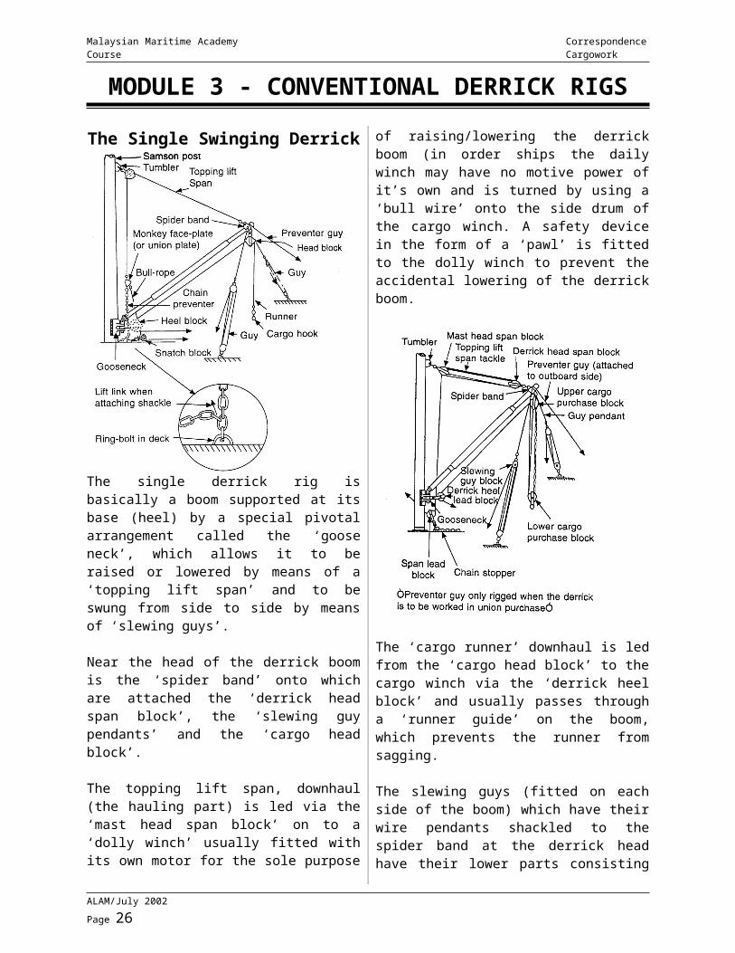
The single derrick rig is basically a boom supported at its base (heel) by a special pivotal arrangement called the ‘goose neck’, which allows it to be raised or lowered by means of a ‘topping lift span’ and to be swung from side to side by means of ‘slewing guys’.
Near the head of the derrick boom is the ‘spider band’ onto which are attached the ‘derrick head span block’, the ‘slewing guy pendants’ and the ‘cargo head block’.
The topping lift span, downhaul (the hauling part) is led via the ‘mast head span block’ on to a ‘dolly winch’ usually fitted with its own motor for the sole purpose of raising/lowering the derrick boom (in order ships the daily winch may have no motive power of it’s own and is turned by using a ‘bull wire’ onto the side drum of the cargo winch. A safety device in the form of a ‘pawl’ is fitted to the dolly winch to prevent the accidental lowering of the derrick boom.
The ‘cargo runner’ downhaul is led from the ‘cargo head block’ to the cargo winch via the ‘derrick heel block’ and usually passes through a ‘runner guide’ on the boom, which prevents the runner from sagging.
The slewing guys (fitted on each side of the boom) which have their wire pendants shackled to the spider band at the derrick head have their lower parts consisting of a cordage tackle for hauling on.
The single derrick rig can be used to lift loads to the full extent of it’s SWL (safe working load), which is marked near the heel of the boom, provided the cargo runner (or cargo purchase) is also rated to that SWL.
NOTE: When a single derrick is used in the Union Purchase rig, a ‘preventer guy’ is passed over its head on the outboard side.
A single swinging derrick which converts a single whip to a double whip and creates a mechanical advantage. Used to lift load double of the SWL of the cargo runner (The derrick must be rated higher).
ALAM/July 2002 Page 19
Malaysian Maritime Academy Correspondence Course Cargowork
YO-YO GearEmployed using two or four single derricks. Used for loads heavier than those, which can be handled by the union purchase or single swinging derrick.
Two DerricksThe two inshore derricks are rigged with a gun tackle and their moving blocks are joined by a heavy strop supporting a floating block (YO-YO) with the cargo hook attached. Operation is carried out by swinging both derricks towards the hatch/quayside, keeping both derricks heads as close together as possible.
Four DerricksTwo pairs of derricks are rigged similar to the union purchase. The two cargo runners of the inboard derricks are passed through a floating block and shackled together; similarly the outboard derrick runners are passed through another floating block and shackled together. The floating blocks are then shackled together to form the union with the cargo hook secured below them.
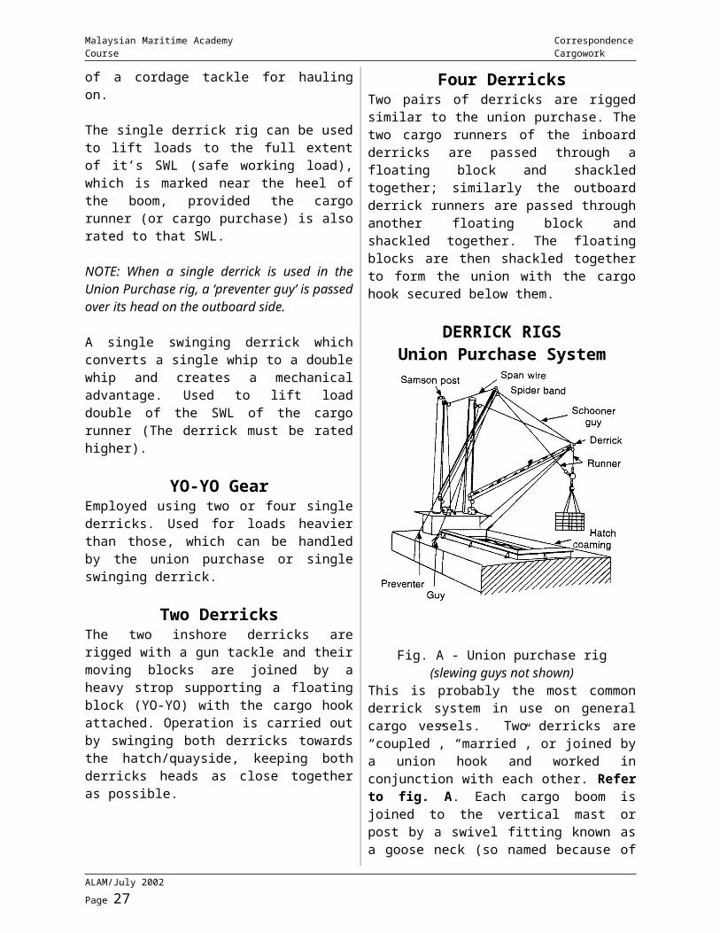
DERRICK RIGSUnion Purchase System
Fig. A - Union purchase rig(slewing guys not shown)
This is probably the most common derrick system in use on general cargo vessels. Two derricks are “coupled”, “married”, or joined by
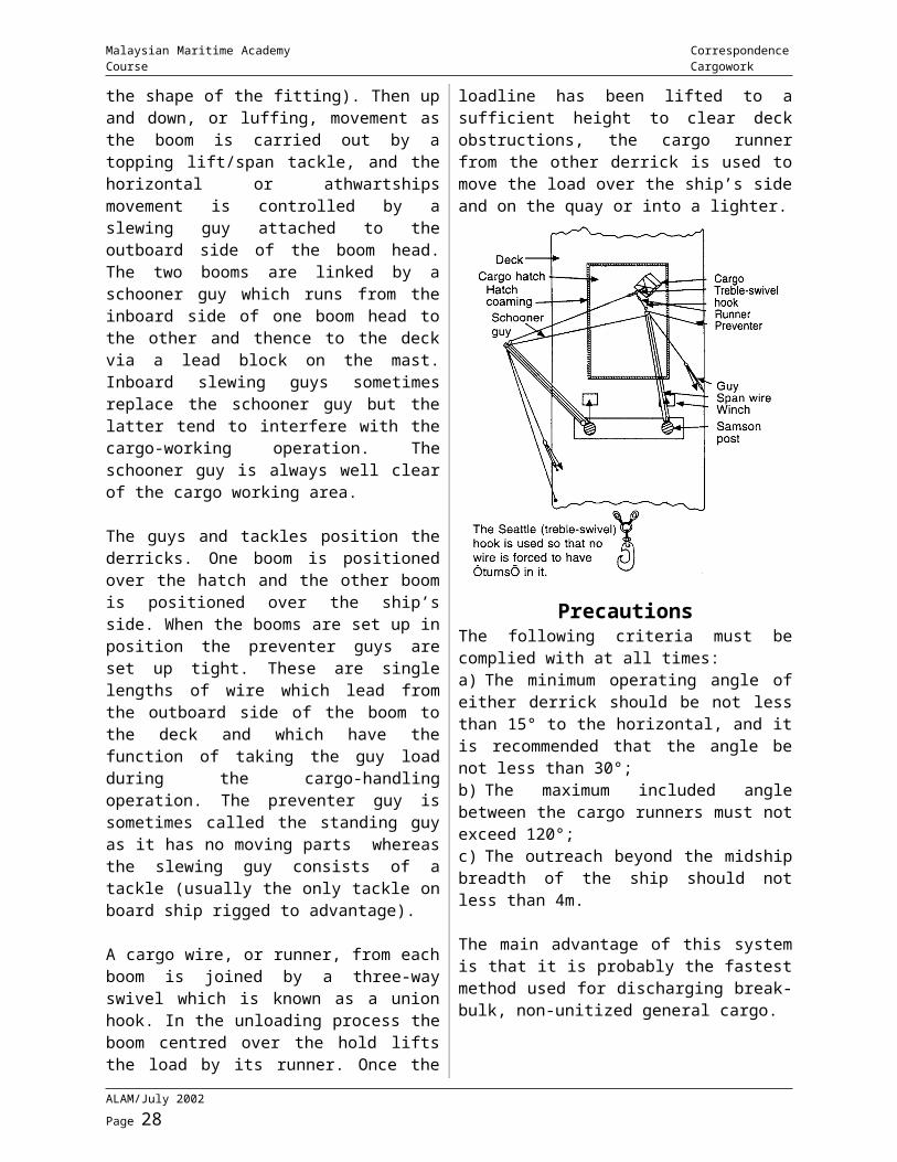
a union hook and worked in conjunction with each other. Refer to fig. A. Each cargo boom is joined to the vertical mast or post by a swivel fitting known as a goose neck (so named because of the shape of the fitting). Then up and down, or luffing, movement as the boom is carried out by a topping lift/span tackle, and the horizontal or athwartships movement is controlled by a slewing guy attached to the outboard side of the boom head. The two booms are linked by a schooner guy which runs from the inboard side of one boom head to the other and thence to the deck via a lead block on the mast. Inboard slewing guys sometimes replace the schooner guy but the latter tend to interfere with the cargo-working operation. The schooner guy is always well clear of the cargo working area.
The guys and tackles position the derricks. One boom is positioned over the hatch and the other boom is positioned over the ship’s side. When the booms are set up in position the preventer guys are set up tight. These are single lengths of wire which lead from the outboard side of the boom to the deck and which have the function of taking the guy load during the cargo-handling operation. The preventer guy is sometimes called the standing guy as it has no moving parts whereas the slewing guy consists of a tackle (usually the only tackle on board ship rigged to advantage).
A cargo wire, or runner, from each boom is joined by a three-way swivel which is known as a union hook. In the unloading process the boom centred over the hold lifts the load by its runner. Once the loadline has been lifted to a sufficient height to clear deck obstructions, the cargo runner from the other derrick is used to move the load over the ship’s side and on the quay or into a lighter.
ALAM/July 2002 Page 20
Malaysian Maritime Academy Correspondence Course Cargowork
PrecautionsThe following criteria must be complied with at all times:a) The minimum operating angle of either derrick should be not less than 15° to the horizontal, and it is recommended that the angle be not less than 30°;b) The maximum included angle between the cargo runners must not exceed 120°;c) The outreach beyond the midship breadth of the ship should not less than 4m.
The main advantage of this system is that it is probably the fastest method used for discharging break-bulk, non-unitized general cargo.
Disadvantagesa) It can only be used for light loads, an average of approximately 1.5 - 2 tonnes per load.b) The winchmen must be highly skilled and experienced.c) The derricks cannot be used for “spot loading”.d) Re-positioning the derricks is time-consuming.
The Jumbo DerrickThis is basically a single swinging derrick with a much greater SWL (about 30 - 50 tonnes). The boom can be raised or lowered, with the
load, by the topping lift span led to a separate winch, and it can be swung from side to side (slewed) by ‘siean guys’ or either side led to separate winches.
In view of the greater SWL, the topping lift span; the cargo fall and the steam guys are all multiple-fold purchases. Further the cargo purchase and the topping lift purchase are rigged advantage (by use or additional ‘lead’ sheaves).
In view of the heavy loads involved and the size of the rig, great care is required for setting it up (which may take up to 2 - 3 hours).
PATENT DERRICKS
Basic Characteristicsi) The twin topping lift/slewing guy principle is used which gives good control of a single derrick.ii) The capability of handling heavier loads than the union purchase system.iii) Combined slewing and topping (luffing) tackles.iv) Very good spot loading facilities. i.e. the load can be set down in most positions within the hatch area.v) A high degree of centralized control with the operation being conducted by one man.vi) The derrick is rigged at all times and can quickly be brought into operation.vii) The use of new technology reduces the stresses encountered with the union purchase system.
There are many patent derrick systems used on board ship but the best known are probably “Hallen” and “Velle” for the handling of general cargoes and “Stuelcken” for heavy lifts.
ALAM/July 2002 Page 21
Malaysian Maritime Academy Correspondence Course Cargowork
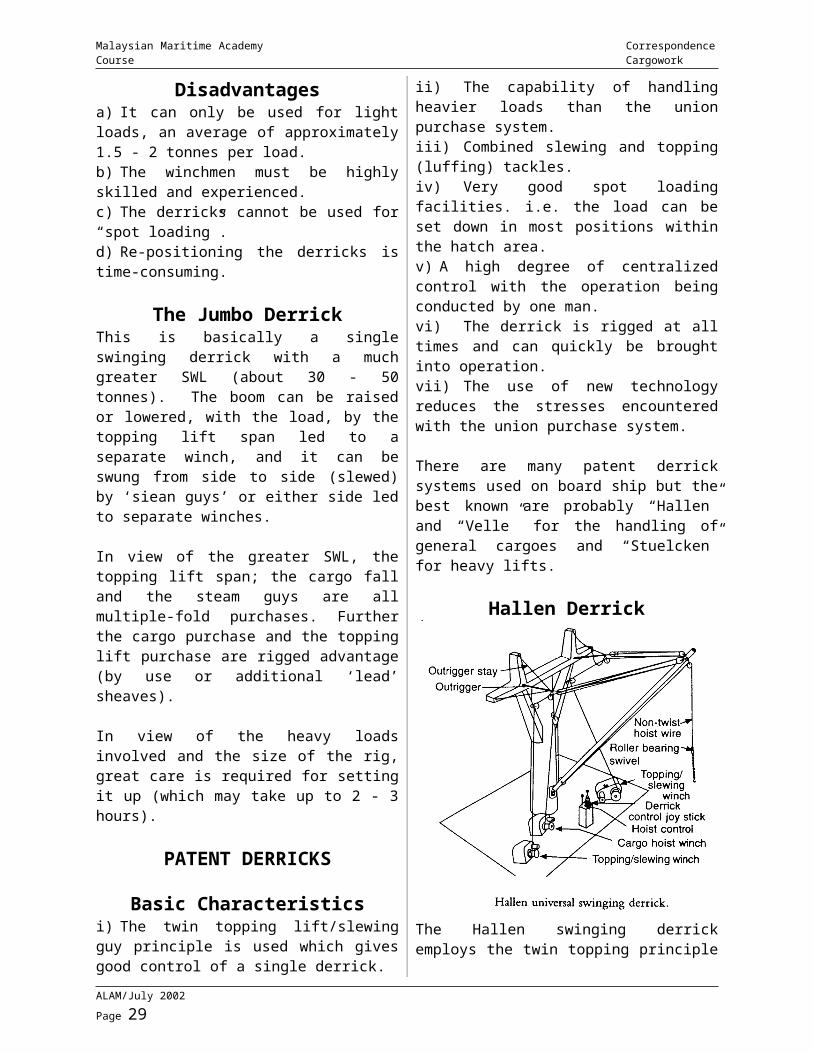
Hallen Derrick
The Hallen swinging derrick employs the twin topping principle which allows good control of a single derrick. This derrick was originally designed for loads of 5 - 8 tonnes but loads of over 100 tonnes are now unexceptional. The derrick can be mounted on all types of mast or derrick post and can make a traverse from port to starboard of 160 - 180°.
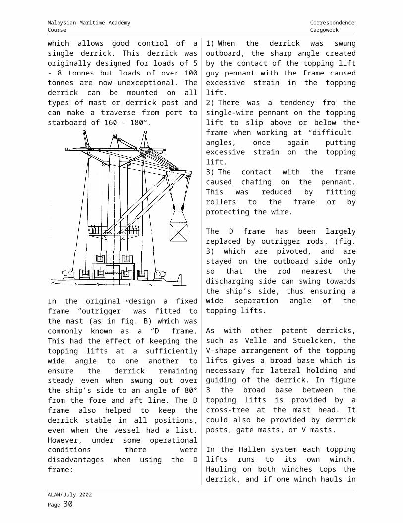
In the original design a fixed frame “outrigger” was fitted to the mast (as in fig. B) which was commonly known as a “D” frame. This had the effect of keeping the topping lifts at a sufficiently wide angle to one another to ensure the derrick remaining steady even
when swung out over the ship’s side to an angle of 80° from the fore and aft line. The D frame also helped to keep the derrick stable in all positions, even when the vessel had a list. However, under some operational conditions there were disadvantages when using the D frame:1) When the derrick was swung outboard, the sharp angle created by the contact of the topping lift guy pennant with the frame caused excessive strain in the topping lift.2) There was a tendency fro the single-wire pennant on the topping lift to slip above or below the frame when working at “difficult” angles, once again putting excessive strain on the topping lift.3) The contact with the frame caused chafing on the pennant. This was reduced by fitting rollers to the frame or by protecting the wire.
The D frame has been largely replaced by outrigger rods. (fig. 3) which are pivoted, and are stayed on the outboard side only so that the rod nearest the discharging side can swing towards the ship’s side, thus ensuring a wide separation angle of the topping lifts.
As with other patent derricks, such as Velle and Stuelcken, the V-shape arrangement of the topping lifts gives a broad base which is necessary for lateral holding and guiding of the derrick. In figure 3 the broad base between the topping lifts is provided by a cross-tree at the mast head. It could also be provided by derrick posts, gate masts, or V masts.
In the Hallen system each topping lifts runs to its own winch. Hauling on both winches tops the derrick, and if one winch hauls in while the others pay out, the derrick slews to the side of the ship on which the hauling winch is located. a third winch is used for hoisting and lowering the cargo. The derrick is controlled by two levers. One lever operates the cargo, purchase and the other lever has a multi-position control for the topping and slewing operation.
Velle DerrickThe Velle swinging derrick also uses three winches. The cargo purchase is operated by a standard type winch but the topping lifts are arranged so that one of the other two winches
ALAM/July 2002 Page 22
Malaysian Maritime Academy Correspondence Course Cargowork
controls the luffing while the third winch is used solely for slewing. Each of the topping lift winches has a split or divided barrel on to which the ends of falls are secured. On the luffing winch the falls are laid on to the split barrels in the same direction. Thus both falls will hoist or lower the derrick simultaneously. On the slewing winch the falls are laid on to the split barrels in opposite directions. Thus when the barrels rotate, one fall pays out while the other heaves in and the derricks slews to port or starboard. The topping lift luffing and slewing winches are operated by a multi-position control lever which is positioned adjacent to the cargo purchase control lever. The operator stands between the levers and operates the cargo purchase with his left hand and controls the derrick movements with his right hand.
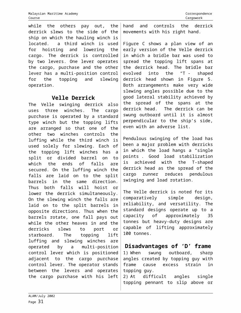
Figure C shows a plan view of an early version of the Velle derrick in which a bridle bar was used to spread the topping lift spans at the derrick head. The bridle bar evolved into the “T”- shaped derrick head shown in Figure 5. Both arrangements make very wide slewing angles possible due to the good lateral stability achieved by the spread of the spans at the derrick head. The derrick can be swung outboard until it is almost perpendicular to the ship’s side, even with an adverse list.
Pendulous swinging of the load has been a major problem with derricks in which the load hangs a “single points”. Good load stabilization is achieved with the T-shaped derrick head as the spread of the cargo runner reduces pendulous swinging and load rotation.
The Velle derrick is noted for its comparatively simple design, reliability, and versatility. The standard designs operate up to a capacity of approximately 35 tonnes but heavy-duty designs are capable of lifting approximately 100 tonnes.
Disadvantages of ‘D’ frame1) When swung outboard, sharp angles created by topping guy with frame cause excess strain in topping guy.2) At difficult angles single topping pennant to slip above or below “D” frame - excessive strain.
3) Contact with frame cause chafing. Reduce by fitting rollers.
Two Levers1) One operates the cargo.2) Other (multi-position) for topping & slewing position.
SHIPS CARGO DECK CRANESSome modern ships are fitted with cranes instead of derricks. Basically they are provided with individual electrical driven motors to permit lifting of the ‘JIB’, slewing of the jib and the working of the cargo hoist.
The ‘JIB’ is a projecting hinged arm and is usually of the luffing type which allows it to ensures hat the hook carrying the weight remains at the same level.
The lifting wire rope is rigged usually as a single whip. It leads over a sheave at the head of the jib and is called the purchase. Between the purchase and the hook is a weight called the ‘ponder ball’. Its function is to help the purchase to over-haul when there is no load.
The crane may be set to move on rails the ship or along the ship or may be fixed centrally with a large reach and angle of slew.
Cranes offer the following advantages: - greater ‘spotting area’ particularly when installed on the vessel centre line, providing greater flexibility. faster loading/discharging rate. less time in preparing for operations. decks clear of guys, stays and other standing/running riggings. self contained and easier to operate.
The main disadvantages of the crane are its higher initial cost and the possible pendulous swinging of the load when slewing is done in a fast manner.
Derrick TestingShip’s derricks are initially tested (initial test) with the boom at an angle of not more than 15° to the horizontal or, if this is impracticable, 30°.
ALAM/July 2002 Page 23
Malaysian Maritime Academy Correspondence Course Cargowork
During its working life, it is recommended that the derrick be retested after any repair to the derrick or permanent fittings, or after any alteration of the rig is not covered by the ship’s plan.
When carrying out a test, the Decks Regulations, form 99 should be consulted, to ascertain whether the accessory gear complies with the statutory requirements. If all is in order, the test may be carried out; otherwise, all loose gear, blocks, shackles, etc., should be sent to works for the necessary treatment in accordance with the statutory requirements laid down in form 99.
The safe working load of the derrick ‘as rigged’ should be checked by reference to the individual safe working loads of the blocks and shackles in the rig, either by direct calculation, or by the preparation of load diagrams. The strength of the wire ropes in the cargo and span purchases should also the checked for the required factor of safety.
If any items of gear are found to be of insufficient strength, either they should be replaced by gear of the appropriate size and strength, or the safe working load of the derrick reduced.
Tests are generally carried out by the use of loads (known as a ‘dead load test’); or by the use of a dynamometer (test clock). It is preferable that the ‘initial test’ be carried out by ‘dead load’.
If no particular derrick a single whip is normally used but the derrick boom and span gear are capable of supporting a cargo load greater than that which may be lifted by a single whip, a proof load may be applied with the cargo runner double up at the derrick head, provided that the ship’s blocks and shackles are used for the test. Where it is found necessary to use the doubling-up method (i.e. a gun-tackle rig), this should be stated on the certificate of test, also the safe working load that may be lifted on a single whip.
When a derrick is rigged with a cargo purchase, and the hauling part of the purchase
is parallel to the boom, the safe working load marked on the upper block in the purchase should be greater than that marked on the lower block. This takes into account the increased resultant load due to the tension in the hauling part of the purchase.
Before applying a proof load to the derrick, all permanent attachments on the mast and derrick should be carefully examined. It is also good practice to rig an adequate preventer span wire rope as a precautionary measure against any part of the span gear ‘carrying away’. This additional span wire rope should not take the mass of the mass of the derrick during test.
When proceeding with the test, the proof load should be applied steadily, and all fittings should be carefully watched for any indication of failure. Apart from watching, it is also desirable to ‘listen’ for any signs of failure.
When testing heavy-lift derricks, care should be taken to ensure that the anchorage for the test clock is of adequate strength, avoiding any risk of structural damage to the ship. For derricks of 30 t safe working load and over, it is advisable to lift moving loads or use a specially designed anchorage on the vessel, and to ensure that there is sufficient stability to avoid excessive list under test. It is also important that shrouds and preventers are properly set up to give adequate support to the mast. Furthermore, slewing guys should be so placed that the angle they make with the derrick boom is not unduly narrow, so that when the vessel heels over under load, they will control the derrick without developing excessive tension.
On completion of the test, a final visual examination of all parts of the derrick rig, and of all permanent attachments on the mast and derrick, should be made before issuing the certificate of test and examination.
In all cases the winches should be carefully examined to ensure that they are in good working order, and that the controls act effectively. Information to this effect should be noted on the certificate of test and examination.
ALAM/July 2002 Page 24
Malaysian Maritime Academy Correspondence Course Cargowork
Every derrick boom should be clearly marked with its safe working load. A certificate of test for this safe working load is required for the derrick ‘as rigged’, and further certificates of test are required for the individual blocks and shackles in the rig, including such items as guy blocks, chain stoppers, etc. The appropriate statutory forms should be used. In the case of wire ropes, a breaking load test (form 87) is required.
A copy of the Docks Regulations, form 99, containing all the prescribed particulars, together with copies of all the appropriate certificates should be kept on board.
DOCK REGULATIONS - Summary
Apply to the process of loading, unloading, moving and handling goods on any wharf, quay or ship.
Part 1. Safety Measures At Dock, Wharf And Quays
1) Fencing. Height of fence not less than 2’ 06” (0.76m).2) LSA in readiness at wharf or quay.3) Efficient lighting.4) First aid boxes, ambulance facilities - whereabouts indicated by notices.
Part 2. Access To And From Ship And Part Of The Ships
Alongside quay: Accommodation ladder properly secured - 22” wide, fence each side to height of 2’ 09”. Alongside other ship Safe means of access, provided by vessel with the higher freeboard. Access to holds etc Applies where hold depth exceeds 5 ft. Ladders in line Ladders provide foothold to depth of not less than 4½” for width of 10” and a firm handhold - Cargo to be stowed so as to leave this clearance. Efficient lighting in holds, on decks, in accessways and all parts where persons employed may go during the course of their work. Hatchcovers
All beams used for hatch covering to have suitable gear for lifting on/off without persons having to go upon them to adjust. All hatch covers to be marked to indicate deck, hatch and position unless covers are interchangeable. Adequate handgrips on hatchcovers.Working space around hatch at least 2 ft.
Part 3. Tests Etc. Of Lifting Machinery
All lifting machinery to be tested before being brought into use and examined by a competent person. All derricks and attachments to masts and deck must be inspected every 12 month and thoroughly examined every 4 years. Other lifting machinery thoroughly examined at least every 12 months. (Through examination = visual examination and hammer test or similar dismantling if necessary). Chains, rings, hooks, shackles, swivels and pulley blocks used in lifting and lowering must be tested and examined before being brought into use. Annealing or similar treatment - ½ “ or smaller at least every 6 months, other at least every 12 months.(Thorough examination = visual examination and hammer test or similar dismantling if necessary). Gears to be inspected before use, unless previously inspected within last 3 months. Ropes to be of suitable quality and free from obvious defect. Wire rope to be tested before being brought into use, inspected every 3 months and if any wire in the rope is broken, every month. If number of broken wires in a length of 8 diameters exceeds 10% of total wire in the rope, it must not be used, nor if it shows signs of excessive wear or corrosion. SWL to be marked on blocks and on ring attached to chain sling. Chain/Wire slings not to be shortened by tying knots in them. Machinery to be securely fenced. Safe access and fencing to crane cabs and driver’s platform. SWL is to be marked on derricks and cranes. Exhaust steam not to obscure any part of deck or access.
ALAM/July 2002 Page 25
Malaysian Maritime Academy Correspondence Course Cargowork
Method of preventing foot of derrick being lifted out of socket.
Part 4. Miscellaneous Rules Means of escape from hold or tween deck where coal or bulk cargo is being worked. No winch drivers or signalmen under 16 allowed. Walking space around cargo stacked on quay. If hold depth exceeds 5 ft. it must be fenced to height of 3ft unless coaming is 2’ 06”. If working cargo in T/D at least one section of hatches to be in place. Signaller to be employed.
Part 5 No person to interfere with gear, etc. unless authorised. Only authorised access to be used. No person to go upon beams to adjust them.
Part 6 If shipowner fails to comply with safe access regulations the duty to do so falls on employer of the persons employed. Register to be kept available for inspection.
ALAM/July 2002 Page 26
Malaysian Maritime Academy Correspondence Course Cargowork
DOCK REGULATIONS - TESTS AND EXAMINATIONS
Every winch and all accessories thereto
Test - Proof load in excess of SWL as follows:- SWL less then 20 Tons - 25% in excess SWL 20 - 50 Tons - SWL + 5 Tons SWL over 50 Tons - 10% in excess
Method - Either weights or spring/hydraulic balance. (DYNAMOMETER).
Every crane/derrick and all accessories thereto
Test - As above
Method - Weights swung as far as possible each way and for crane with variable jib at maximum and minimum radii as well. Derricks to be positioned at lowest working angle.
Loose Gear Whether Accessory Or Not
Test - Proof load as follows:Chain, ring, hook, shackle or shivel - 2 x SWLSingle sheave blocks - 4 x SWLMultiple sheave blocks:SWL less than 20 Tons - 2 x SWLSWL 20 - 40 Tons - SWL + 20 TonsSWL over 40 tons - 1½ x SWL
Examination - After test of all gear, including dismantling of blocks to see that no damage or deformation has occurred.
Wire RopesTest - Sample tested to destruction. SWL not to exceed 1/5th of breaking load.
STRESSES IN DERRICK RIGSTo avoid the possibility of accidental failure (breakdown) of derrick rigs, due to overloading, it is essential to know the stresses likely to be experienced by the various parts of the rig when lifting a load.
Estimates of the stresses involved may be made by resolution of ‘parallelograms of forces’ and in some cases by use of empirical formulae.
1) In the Single Swinging DerrickThe main areas of stresses, when lifting a load by a single derrick would be: -a) the stress on the hauling part of the cargo runner/tackle.b) the resultant load on the cargo head block.c) the tension in the topping lift span.d) the resultant thrust on the derrick.e) the resultant load on the heel block.f) the resultant load on the mast head span block.
Various factors are considered when making estimates of derrick stresses, and for a basic understanding, an example is explained with the rig parameters given below:
“A single swinging derrick boom, 16m long and weighing 1 tonne, makes an angle of 60 to the horizontal when suspended by a single span topping lift with the mast head span block secured 13m above the heel.
A load of 5 tonnes is to be lifted using a gun-tackle rigged to disadvantage, secured at the derrick head, with its hauling part led parallel to the derrick to the winch via a heel block. The heel of the derrick is 3m above the deck, and the winch point is 3m from the mast and 2m above the deck. The lifting gun tackle itself weighs 0.2 tonnes”.
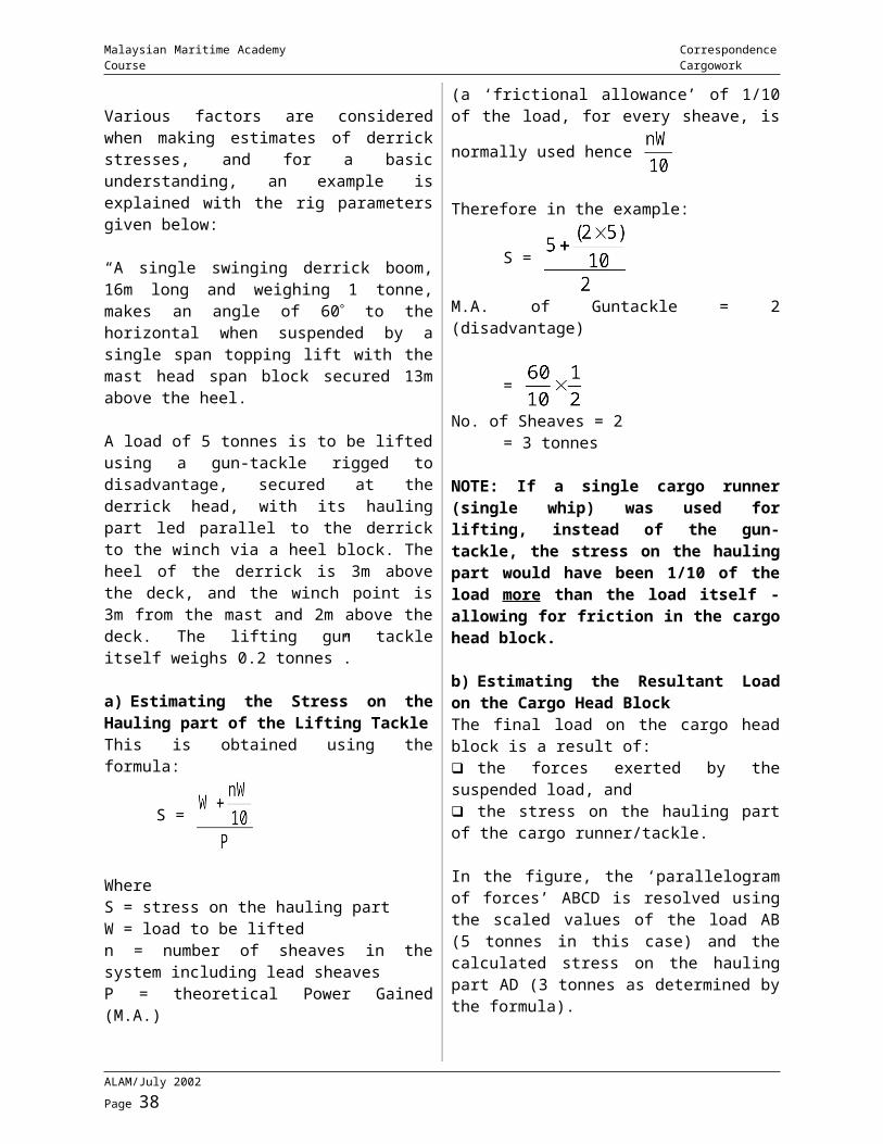
a) Estimating the Stress on the Hauling part of the Lifting TackleThis is obtained using the formula:
S =
Where S = stress on the hauling partW = load to be lifted
ALAM/July 2002 Page 27
Malaysian Maritime Academy Correspondence Course Cargowork
n = number of sheaves in the system including lead sheavesP = theoretical Power Gained (M.A.)
(a ‘frictional allowance’ of 1/10 of the load, for
every sheave, is normally used hence
Therefore in the example:
S =
M.A. of Guntackle = 2 (disadvantage)
=
No. of Sheaves = 2= 3 tonnes
NOTE: If a single cargo runner (single whip) was used for lifting, instead of the gun-tackle, the stress on the hauling part would have been 1/10 of the load more than the load itself - allowing for friction in the cargo head block.
b) Estimating the Resultant Load on the Cargo Head BlockThe final load on the cargo head block is a result of: the forces exerted by the suspended load, and the stress on the hauling part of the cargo runner/tackle.
In the figure, the ‘parallelogram of forces’ ABCD is resolved using the scaled values of the load AB (5 tonnes in this case) and the calculated stress on the hauling part AD (3 tonnes as determined by the formula).
The resultant force at ‘A’ represented by the scaled value of AC, is the resultant load on the cargo head block (equals 7.8 tonnes in this example).
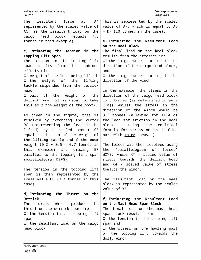
c) Estimating the Tension in the Topping Lift SpanThe tension in the topping lift span results from the combined effects of: weight of the load being lifted
the weight of the lifting tackle suspended from the derrick head part of the weight of the derrick boom (it is usual to take this as ½ the weight of the boom).
As given in the figure, this is resolved by extending the vector DC (representing the load to be lifted) by a scaled amount CE equal to the sum of the weight of the lifting tackle and ½ the boom weight (0.2 + 0.5 = 0.7 tonnes in this example) and drawing EF parallel to the topping lift span (parallelogram DEFG).
The tension in the topping lift span is then represented by the scale value FE (3.4 tonnes in this case).
d) Estimating the Thrust on the DerrickThe forces which produce the thrust on the derrick boom are: the tension in the topping lift span the resultant load on the cargo head block
This is represented by the scaled value of AF, which is equal to AD + DF (10 tonnes in the case).
e) Estimating the Resultant Load on the Heel BlockThe final load on the heel block results from the stresses in: the cargo runner, acting in the direction of the cargo head block, and the cargo runner, acting in the direction of the winch
In the example, the stress in the direction of the cargo head block is 3 tonnes (as determined in para 1(a)) whilst the stress in the direction of the winch would be 3.3 tonnes (allowing for 1/10 of the load for friction in the heel block - using the empirical formula for stress on the hauling part with three sheaves).
The forces are then resolved using the ‘parallelogram of forces’ WXYZ, where XY = scaled value of stress towards the derrick head and XW = scaled value of stress towards the winch.
ALAM/July 2002 Page 28
Malaysian Maritime Academy Correspondence Course Cargowork
The resultant load on the heel block is represented by the scaled value of XZ.
f) Estimating the Resultant Load on the Mast Head Span BlockThe final load on the mast head span block results from: the tension in the topping lift span and the stress on the hauling part of the topping lift towards the dolly winch
In the example, the tension in the topping lift span is 3.4 tonnes (as determined in para 1(c)) whilst the stress on the hauling part of the topping lift towards the dolly winch would be 3.74 tonnes (allowing for 1/10 of the topping lift tension for friction in the mast head span block).
The forces are resolved using the ‘parallelogram of forces’ MNOP, where MN = the scaled valve of tension in the topping liftspan and MP = the scaled value of stress in the hauling part of the topping lift, towards the dolly winch.
The resultant load on the mast head span block is represented by the scale value of MO.
Assignment
Please complete the assignment and return to ALAM
1) Explain the advantages and disadvantages of a union purchase in cargo operation.
2) A derrick 24 m long is supported by a span 12 m long. Attached to a point on the mast 20 m vertically above the heel of the derrick a guntackle is rove to disadvantage is used to lift a weight of 10 tonnes. Span tackle also a guntackle is rove to disadvantage. The mass of the boom is 2 tonnes and the mass of cargo gear is 0.5 tonnes. Find the stress on:
i) Derrick head purchase block shackle.ii) Derrick heel block shackleiii) The load on the mast head span block shackleiv) The thrust on the derrick
(After leaving the heel block runner makes an angle of 600 with mast)
ALAM/July 2002 Page 29
Malaysian Maritime Academy Correspondence Course Cargowork
MODULE 4 - ROLL ON/ROLL OFF SYSTEMS
Ro/Ro vessels promote wide and comprehensive forms of unit carriage, from palletization on basic form to heavy vehicular traffic, including containers. Mechanization is highly developed with mobile forms of handling continually increasing in adaptability, and ship design forms provide for entry and exit of cargoes in a variety of fashions. One of the most important economical aspects of these types of vessels is the quick turn around. Ro/Ro vessels now operate with either or a combination of bow, stern, quarter or slewing ramps, which increase their versatility. Related to these forms of ship construction are interesting facts concerning the ship to shore interface. Heights, slope, inclination and overall dimensions also take into account the types of cargoes likely to be handled. There are some ramps (link spans) which can service double decks.
StowageMany Ro-Ro vessels have a predominance of the weight (e.g. ramp systems) aft. This may require that tanks are used to maintain an acceptable trim during loading operations, and may also require that cargo is first in and last out - to the forward lower decks. Cargo may be taken on board the Ro-Ro vessel in one or more of the following ways: -a) road vehicles with integral haulage power which will also remain with the vessel.b) road trailers which will remain with the ship throughout the sea transport leg.c) roll trailers which are not suitable for road haulage but which will remain with the ship during sea transport.d) cargo towed on board using roll trailers, and then cargo removed and stowed without its wheels.e) cargo secured on flats and carried on board wither using roll trailers or by other mechanical handling equipment; both the flat and its cargo being stowed as a unit.f) pallets either singly or in groups carried on board using roll trailers or fork lifts trucks.g) individual items of cargo brought on board by fork lift trucks.
Vehicles are usually close parked in lanes of about 3 metres wide. This should allow access for lashing gangs to secure each vehicle properly. Containers may be stowed fore and aft or athwartships, but care must be taken to ensure that suitable strengthened areas of the deck are in the way of the corner castings.
Trailers may be backed up the ramp and positioned so that at the port of discharge towing vehicles may have direct access to the coupling point of each trailer, and be able to tow straight off the vessel without the need to turn around. It is important that different types of cargo e.g. containers and pallets, are properly separated to prevent the one causing damage to the other.
This separation, which in many cases also provides restraint, may be by means of timber dunnages, dunnage bags, sheets of plywood or hard board, and other cargo e.g. tyres etc. Where containers with air cooled integral refrigeration units are stowed below decks, it must be ensured that adequate ventilation can reach these containers to allow proper air cooling to take place, as well as sufficient space, in way of the equipment end of the container, so that maintenance may be carried out and temperatures monitored. Appropriate Dangerous Goods regulations apply to all dangerous goods cargo. These should be segregated from other vulnerable cargoes and closely available to fire fighting provisions.
SecuringSecuring of vehicles on board Ro-Ro vessels must be in accordance with an approved system, making full use of trestles, pedestals, deck securing points, as are recommended by the builders. Securing points and appropriate trestles etc., should be used to by-pass the springing system of vehicles in order to secure them. Containers should be lashed and secured in accordance with an approved system, preferably to locating cones and securing pins, wire, chains, hooks and levers must be set up so as not to take undue strain and there by rack or distort the container.
ALAM/July 2002 Page 30
Malaysian Maritime Academy Correspondence Course Cargowork
There should be a sufficient number of men who have been trained in the use of the securing equipment and in the most effective methods of securing various types of vehicles (cargo units, so that proper lashing operations are completed before the vessel proceeds to sea. The following precautions should be taken.
a) All vehicles should, as far as is possible, be stowed in a fore and aft direction with the hand brakes on and the engines in gear. Any vehicle stowed athwartships must be securely lashed.b) The suspension units of heavy vehicles or trailers should, wherever practicable be relieved by the use of jacks, after which the vehicles and trailers should be securely lashed in their stowed position.c) Every stowed vehicle having a road laden weight in excess of 2 tonnes which is not fully balanced, should be supported at one end by jacks, rests, trestles or table laid on friction pads and then secured by lashings at both ends and at the sides as necessary.
d) All lashings should have efficient tightening devices.
There are several variable factors which affect the number and strength of lashings needed. Some of them are as under: -1) The weather conditions and duration of voyage.2) The size and weight of the vehicle of cargo unit and the position of its centre of gravity.3) The positions of the wheels, or trestles, in relation to the cargo load, as this affects the fulcrum position and hence the tipping moment.4) The position and angle at which the lashings are inclined.5) The coefficient of friction between the various bearing surfaces.6) The safe working load of the lashing equipment.
Probably the most effective method of dealing with this complex problem is to rely on experience and past practice – i.e. to employ lashing arrangements which have proved successful at times when very severe weather conditions have been encountered. Where such proven lashing arrangements are available, they should be displayed, either diagrammatically or in a tabular fashion on specially prepared notice boards posted in the vehicle spaces.
ALAM/July 2002 Page 31
Malaysian Maritime Academy Correspondence Course Cargowork
CONTAINERISATION
It is a practice of grouping loads of cargo together and stowing them in ONE container to protect and preserve them and to ensure their efficient distribution. Containers are “PHYSICAL CAPSULES”, made of steel, aluminium, plastic or wood to hold a large member of individual units for shipment. In short, they are boxes usually of metal with doors and lifting points.
The use of containers is international along with their construction. Hence, variations in design and applications can be expected. To standardized the equipment for international use, a body known as ‘INTERNATIONAL STANDARDS ORGANISATION (ISO)’ has been formed. This organisation is mainly responsible for setting standards in respect of construction, durability, fixtures and attachments and for methods of handling, lifting and slinging of containers. The Codes and Practices of the ISO are issued in a publication on ISO container standards and recommendations, which should be read and understood by all officers serving on container vessels.
Freight ContainerAccording to ISO, a freight container is an article of transport equipment: -1) of a permanent character and accordingly strong enough to be suitable for repeated use;2) specially designed to facilitate the carriage of goods, by one or more modes of transport, without intermediate reloading;3) fitted with devices permitting its ready handling, particularly its transfer from one mode of transport to another;4) so designed as to be easy to fill and empty;5) having an internal volume of 1 cubic metres (35.3 cubic feet) or more.
There are many types of containers in use throughout the world today, some of them are as shown below: -
1) Non-Collapsible Freight Container
Its rigid in construction and its components are permanently assembled.2) Collapsible Freight ContainerIt can easily be dismantled and parts of which easily folded and then fitted together again.
3) Side LoaderIt is also of standard size, having one or more openings on its sides.
4) Open TopAlso of standard size, having no roof.
5) Half Height ContainerIt is a container having standard size except for height which is only 4 feet. It is used for cargoes of low stowage factor, and heavy weights like steel plates and machinery plates. The sides can be completely opened by unhinging them. The roof is generally soft, that is covered only by a canvas or plywood. It has a capacity of about 400 cubic feet.
6) Insulated ContainerIt is of standard size but with internal insulation of polyurethane type fitted between a plywood lining and the outer skin.
7) RefrigeratedThese are standard size containers carrying refrigerated cargoes and having their own machinery for cooling.
8) Specialized ContainersThere are so many special types of containers, used for dry bulk cargoes and chemicals in powder form. Liquids can also be carried in these pressurized tanks or liquid containers.
Standard Size Of A Container
Containers used in international trade constructed according to the specifications of International Organisations\ (ISO). Following are the standard sizes of containers: -
1) Twenty Feet Unit (20 Feet X 8 Feet X 8 Feet)
ALAM/July 2002 Page 32
Malaysian Maritime Academy Correspondence Course Cargowork
This is the size most commonly used in the world container traffic, to facilitate carriage by sea, road or air having standard points for lashing, scurrying and lifting. Containers are made of steel having a capacity of about 1000 cubic feet. Each container weighs about 2 tons and can handle cargo of about 20 tons.
2) Two TEUs (40 Feet X 8 Feet X 8 Feet) Weight of container = 3.5 tons CARGO CARRYING CAPACITY = 30 to 35 tons
3) Small Size (10 Feet X 8 Feet X 8 Feet)
4) Medium Size (30 Feet X 3 Feet X 8 Feet)
Carrying Capacity Of A ShipThe container carrying capacity of a ship is indicated by how many twenty feet containers a vessel is constructed and classified to carry. It is denoted by the term TWENTY FEET EQUIVALENT UNIT (TEU). Hence, one 40 feet container is 2 TEUs. A container vessel of
350 TEU will carry 350 number of standard twenty feet containers.
Advantages Using Containers
1) Speed and economy in handling, particularly at the ports. One gang of twelve or thirteen men can discharge and load a fully loaded container ship in three to four days instead of a hundred men taking three to four weeks.2) Safety, both as regards breakages and pilferage, especially when transporting sophisticated electrical goods like radios, TVs, VCRs etc.3) Packing can be reduced.4) A real door-to-door service can be offered.
Disadvantages1) Financial: Massive capital outlay for the ship which is more expensive than a conventional general cargo ship.2) Each ship needs three sets of containers, that is one at loading terminal, one on the ship and one at the discharging terminal. An ordinary container is a very expensive item of equipment.3) Repairs and maintenance of containers being very expensive. Reefer containers are even more expensive to get, repair and maintain.4) Special terminals will have to be constructed with expensive high speed cranes capable of lifting forty tons and more weights.5) Expensive machines must also procured to move the containers around the terminal.6) Unprofitable movement of empty containers produces a problem of an imbalance of trace.7) In certain countries there are customs, documentation and legal difficulties.
Design Of A ContainerContainer is designed and constructed as per the recommendations and specifications of the ISO. In order to make sure that a container has been produced up to the standards, it has to be proved that its structural calculations are correct and that it can withstand strength testing. For that reason, such organisations as Lloyd’s Register, Bureau Veritas and the American Bureau of Shipping, engaged in the
ALAM/July 2002 Page 33
Malaysian Maritime Academy Correspondence Course Cargowork
certification of containers granted on the basis of conformity to an approved type, have established regulations and procedures of a rigorous nature, mostly based on ISO recommendations.
Material UsedSteel seems to be the best basic material. It is superior in yield, tensile and sheer strength and at the same time its elasticity is of a high rank. Steel is also cheaper. Some containers are of mixed construction with frames and castings of steel and sides and walls of aluminium. Some countries are using wooden, plywood and plastic containers. Fibreglass reinforced plastic overlaid plywood containers are successfully produced. Stainless steel containers are used for transporting specialised cargoes, like foodstuff, chemicals, liquor, wines etc.
The main parts of a container are: -1) WALLS: The container walls are not load bearing, they merely provide weather protection and security to the cargo within the container. Glass reinforced plastic, aluminium and even plywood can be used, but for a longer life of a container and to give strength and rigidity STEEL is the material used.
2) CORNER POSTS: Main strength of a container lies in its corner posts. Containers are stacked six high, thus, corner posts should be strong enough to withstand these stresses.
3) CORNER CASTINGS: These are built into the top and bottom of each corner post and provide means of lifting and lashing a container. The top of the casting has an elongated hole for twistlocks of lifting machinery and the sides have smaller holes for lifting hooks of conventional cranes and for lashing.
4) DOORS: Doors may be at the ends or sides, which can be opened fully to give complete access to the cargo. Rubber strips around each door and strong bolting system ensures that the container is watertight. The frame of the door is also made of steel for strength and rigidity. For security reasons, the bolts of the doors are sealed.
Testing And NumberingContainers must be examined and tested every 2½ years by Classification Society Surveyors and a certificate issued. A small plate is also fixed onto the container indicating the date of such survey.
For identification purposes, containers carry the letters of their owners, like OCL (Ocean Container Lines), NOL (Neptune Orient Lines), MISC (Malaysian International Shipping Corp.) etc. A series of figures also follow these letters, which indicate the type of a container.
FCLWhen a container is completely filled with the goods from a shipper to a consignee, the container is being used as a FULL CONTAINER LOAD.
LCLWhen a container is being used by a shipper to transport goods belonging to various
ALAM/July 2002 Page 34
Malaysian Maritime Academy Correspondence Course Cargowork
consignees, only part of a container is being utilized for each and every consignee in a same PORT, the container is than said to be used as LESS THAN A CONTAINER LOAD.
CONTAINER VESSEL DESIGNThe main object in the design of container ships is to carry the maximum number of containers within the designed length and breadth having regard to the form and structural arrangement. Adequate structural strength must therefore, be provided.
FramingLONGITUDINAL framing throughout the main body of the vessel. TRANSVERSE framing in the forepart and afterpart of the vessel.
GirdersContainer vessels are built having CELLULAR construction at the sides, strong longitudinal box girders are formed, port and starboard side, by the upper deck, second deck, top of shell plating and top of the longitudinal bulkheads. High tensile steels are used in the upper deck and strake to form a strong box girder. These box girders in addition to providing longitudinal strength provide stiffness against racking stresses as well as being useful tank spaces.
HatchwayHatchway is divided into three sections and two long hatch girders are fitted. These girders are continuous, so that the longitudinal bending strength is shared throughout the length of the girders and also provide additional section modulus.
HatchesHatches or container spaces are suited for the standard size of container (20 feet or 40 feet units). A form of bulkhead is fitted at interclass of 14.70 metres (48.2 feet), center to center with watertight bulkheads as per the Classification Society Rules and Specifications. These bulkheads resist racking stresses, giving support to the double bottom structure.
DeckContainers are also carried on deck resulting in high deck loading. Thus, the deck and hatch covers must be strengthened to withstand this extra loading.
GuidesThe container guides and adjacent structures are designed to withstand dynamic forces due to rolling, pitching and heaving. The guides consist of angle bars approximately 150 mm x 150 mm x 14 mm connected to the vertical webs and adjoining structure and are spaced 2.60 metres apart. The bottom of the guides are bolted to brackets and welded to the tank top and beams. These brackets are welded to doubling plates about 15 mm thick which are welded to the tank top.
Container CellsThe individual container cell is formed by four vertical guides located at each corner of the container stack running from the hatch coming down to the tank top. The guides have three related functions which are as follows: -a) To guide the containers down to their stowed position even though the vessel may be listing or the crane not perfectly centered over the cell.b) To land any container on top of the container below it within prescribed tolerances so that the superimposed loads on these lower containers do not exceed the peculiarities for which they are designed.c) To hold the containers in their stacked position and absorb the horizontal forces
ALAM/July 2002 Page 35
Malaysian Maritime Academy Correspondence Course Cargowork
imposed on them by the containers due to the motion of the vessel in the sea. Containers are just LIFTED-ON and/or LIFTED-OFF.
TYPES OF CONTAINER SHIPSContainer ships can be divided into following categories: -
1) Full Container ShipsThese are ships with special features and arrangements to carry only containers in all available spaces. Hence, they are generally SINGLE-PURPOSE ships. These single-purpose ships only move containers, stacked on top of each other in vertical stacks on deck. Loading is achieved by lowering the container into a cell or stack, vertically to its stowed position without further shifting in the horizontal plane. During discharge, the reverse procedure is followed. The containers can be stacked on deck up to four high. This extends the carrying ability of a ship beyond the confines of the hull and lessen the cubic losses sustained by the squaring off of the ship’s hold. The limiting forces here are the ship’s stability and satisfactory means of securing the containers in place.
The biggest and fastest and also the most expensive container ships are those of the SEA-LAND 7S CLASS. They have a capacity of 1096 containers of 35 and 40 feet, a maximum speed of 33 knots and cross the ATLANTIC from New York to Rotterdam in four and a half days.
Other well known Shipping Companies which operate all container vessels are: -a) MALAYSIAN INTERNATIONAL
SHIPPING CORPORATION (MISC)b) NEPTUNE ORIENT LINES (NOL)c) AMERICAN PRESIDENT LINES (APL)d) AUSTRALIAN NATIONAL LINES (ANL)e) OCEAN CONTAINER LINES (OCL)f) KAWASAKI KISEN KAISHA (K-LINES)g) SCAN DUTCH LINES & AMERICAN
EXPORT ISBRANDISEN LINESh) Sea Land, Sea Train, Snow Shipping and
United States Lines.
2) Partial Container ShipsIn these ships ONLY part of the vessel’s capacity is especially designed for containers. The vessels of Atlantic Container Line and Care Line belong to this category as they carry not only containers, but also every type of general cargo on its own wheels or tracks or on trailers. The containers are lifted-on/lifted-off, while the trailers and other rollable cargo including cars are rolled-on/rolled-off over the stern ramp and through the stern door. These multi-purpose ships employ a combination of different cargo handling systems. The ships of this category vary in size from 16,500 to less than 500 gross tonnes. The Japanese NYK
ALAM/July 2002 Page 36
Malaysian Maritime Academy Correspondence Course Cargowork
Line projected a big ship, 14,000 dwt for the Japan to Australia rotate.
a) Convertible Container ShipsIn these ships part or whole the vessel’s capacity may be used for either containers or other cargoes and embodying special features which permit their convertibility on a voyage to voyage bases. These ships are used to transport containers and cars from say Yokohama (Japan) to Hawaii, while returning with containers, sugar and molasses in bulk.
b) Limited Container ShipsThese are ships of limited container-carrying capacity in which some container handling and securing devices are installed, but otherwise they are of normal construction carrying general, bulk and liquid cargoes.
c) Conventional ShipsThese are ships without special containers - stowing or handling devices. On these ships, container is merely treated as a larger than usual piece of cargo. It is secured and stowed by conventional means. Such ships could conventional general cargo ships and roll on, roll-off vessels with four steel decks below the water deck, all linked by sloping ramps. Containers are handled with shipborne equipment like forklifts with a side lift frame for 20 feet containers and forks for boxes, pallets and cases. These ships normally have a capacity of 21,700 dwt and 1,910,000 cubic feet bale capacity. Remarkable ramps are mounted aft on starboard side, 105 feet long, weighting 150 tonnes and can bear loads up to 105 metres or less space on the quay. This hinged angled stern ramp can be continuously adjusted to tide and draught.
SPECIAL TYPES OF SHIPS
1) Barge CarriersThere are two such specially designed ships which carry barges or lighters: -
a) LASHIt stands for ‘LIGHTER ABOARD SHIP’. Lighter or barges are independently floating, universal units without the propulsive power, and loaded with cargo of very different kinds,
unitised as well as bulk, liquid, commodities or even heavy lift items.
These floating units can be towed or pushed in ports and on inland waterways and hoisted aboard the mothership for transport by sea. Besides flexibility, their advantage is that they can bypass traditional berth facilities in congested ports, releasing the door-to-door water transport, further reducing cargo handling, warehousing, inventory costs, risks of loss and damages.
Particulars of a typical LASH ship are: -CARRYING CAPACITY = 61 to 73 lightersLIGHTER SIZE (each) = 61 ft. 6 in. x 31 ft. 2 in x 13 ft.WEIGHT of each lighter = 400 tonnes approx.GROSS TONNAGE = 26400 to 39000 tonnesLENGTH = 814 feetBEAM = 100 feetSPEED = 19 to 22.5 knots
Lighters or barges are constructed of fiberglass to boost the payload and facilitate handling, as well as reducing maintenance. The ship can also be loaded with containers, as many as 1200 units of 20 feet. A lash ship can be filled within 24 hours with 49 barges and 356 containers by means of a travelling shipboard crane of 500 tonnes capacity, supplemented by a gantry capable of lifting upto 35 tonnes.
Feeder vessels are now in use. The NACAT (BARGES ABOARD CATMARAN) are merely floats or rafts formed of a number of logs tied side by side some distance apart. They ferry lighters to the mother ship, which operates only a limited number of major ports-of-call and reduces port turnaround times.
b) SEABEELykes Lines is a major shipping company, owning a fleet of SEABEE ships. Seabees are an impressive improvement on the theme of carrying standard barges on a large sea going vessel. Seabee is a ship operating solely as a deep sea transport of pre-loaded barges having real extensions to provide service directly to the ports and other waterside loading locations. Seabee permits all types of cargoes whether unitised, bulk, break-bulk,
ALAM/July 2002 Page 37
Malaysian Maritime Academy Correspondence Course Cargowork
palletised, containerised, and heavy lifts. She can also be converted into a roll-on/roll-off vessel and can exclusively move containers. The barges which carry cargoes, are the extensions of mothership allowing the Seabee herself to avoid the risk run by any big ship going into port and to develop the technique of discharging offshore.
Particulars of a typical Seabee are: -CARRYING CAPACITY = 1,500 tonnes to 1,800 containers of standard 20 feet. Plus 15,000 tonnes of liquid in deep tanks.AS ROLL-ON/ROLL-OFF = 5 kilometres of ALLEYS with a width of 2.8 metres.LENGTH = 276 metresBEAM = 32.5 metresDEADWEIGHT = 27000 tonnes approx.SPEED = 20 knotsBARGES SIZE = 29.1 metres x 10.7 metresNO. OF BARGES = 38 each weighing 800 tonnesBALE CAPACITY = 39,000 cubic feet
They also have a heavy lift subversive elevator at their stern with a capacity of 2000 tonnes to load and discharge two barges at the same time. Theoretically, the complete loading or discharging operation takes about 13 hours. From the elevators, power operated transporters bring the lighters to and from their storage location.
The main difference between the Lash and Seabee is the number and capacity of the barges each can transport. Lash carries upto 73 barges with a capacity of 400 tonnes each and bale space of 15,900 cubic feet, whereas the Seabee carries 36 with 800 tonnes each and bale space 39,000 cubic feet. Furthermore, LASH uses a shipboard travelling crane, whereas Seabee employs and elevator for the mechanical handling of these lighters.
CONTAINER HANDLING EQUIPMENT
Different types of container cranes are used to load and unload container ships. Many shipping companies started their container operations using shipboard gantry cranes. The advantage of shipboard handling
equipment is that ships can call at ports which have no costly custom-built installations like gantry cranes etc.
CranesIn the major ports of the world there are special CONTAINER BERTHS, where two kinds of cranes are used: -a) Portainer CraneThis is a gantry with usually ONE boom, which merely moves the containers from the ship’s hold onto flat beds of lorries and forklift trucks on the quay. This crane is employed in major container ports, where large container ships arrive regularly and where storage space and marshalling yards are consequently big or situated near the quay.b) Transtainer CraneIt is a crane of the overhead travelling type, which spans a storage place or marshalling yard. It is multipurpose crane, capable of unloading ships, moving containers to their storage place, loading trucks and trains and, between the arrivals of vessel it can be employed for marshalling. Its speed is low in comparison with portainer crane. This crane is perfectly suitable for ports with moderate output.
SpreadersEvery container crane has a rectangular spreader frame with coupler latches in the corners. These twist locks enter into the top holes of a container corner castings as the spreader is lowered onto the container. Latches are locked and unlocked electrically, hydraulically or pneumatically. Retractable alignment arms keeps the spreader in position. ISO Recommendations gives the specifications of corner fittings for freight containers.
ALAM/July 2002 Page 38
Malaysian Maritime Academy Correspondence Course Cargowork
Fork LiftsFront loading or side loading fork lifts are in common use as container handling equipment.
SECURING CONTAINERSWhen loading containers on deck of the full container and roll-on/roll-off vessels, separate lashing arrangements would have to be made. The problem of lashing different sizes of containers is further aggravated by different container heights and maximum permissible gross weights of various types of boxes. Each ship carries a large stock of fittings, wires, bottle screws, turnbuckles and ratchets. Hooks and chain tensioning devices secure the vehicles to an elephants’ foot located in a deck flush fitting with four slots in the form of a cross, radiating from a central hole. First tier of container is lowered over removable stud on the hatch covers and decks and a safety metal pin inserted through corner castings and studs. The second tier is fixed into the first tier by inserting single or double bridging pieces into the corner castings, or both the tiers.
Inside the holds the containers are held in place by the cell guides.
On deck further lashings of wire, chains and rods are provided, tightened by bottle screws and turnbuckles. On some vessels lashing bridges are constructed.
ALAM/July 2002 Page 39
Malaysian Maritime Academy Correspondence Course Cargowork
ALAM/July 2002 Page 40
Malaysian Maritime Academy Correspondence Course Cargowork
DECK CARGOES
The carriage of deck cargo - governed by Statutory Instrument 1968 No. 1089.
1) The vessel must have adequate stability at all stages of the voyage. Cargoes such as coke and timber can absorb upto about a third of their own weight of water. Losses of weight such as those due to consumption of fuel, water and stores must also be considered. Upsetting moments - wind taken into account.
2) Adequate provision for safety of crew when passing from one part of the vessel to another - a walkway has to be provided over the cargo. Walkway not less than 1 metre in width, not less 3 courses of guard rails or wires supported by stanchions intervals not more than 1.5m. The vertical opening between lowest rails or wires not to exceed 230mm and no opening above that shall exceed 380mm.
3) Steering arrangements - effectively protected from damage. Breakdown in the main steering arrangements - emergency gear.
4) Where the cargo is stowed on the hatches - properly battened down, sufficient strength to take the intended cargo.
5) Deck - sufficient strength for the intended cargo. If necessary strengthened by tomming or shoring underneath.
6) Deck cargo - well secured, protected from weather. Not so high as to interfere with the navigation of the ship.
ALAM/July 2002 Page 41
Malaysian Maritime Academy Correspondence Course Cargowork
REFRIGERATED CARGOES
DefinitionAny cargo that has to be loaded, maintained and/or carried at a certain temperature in order for it to reach its destination without deterioration is classed as refrigerated cargo. This includes meat, fish, poultry products, dairy products, drugs and experimental samples.
Types Of Refrigerated Cargoes
1) Goods carried in frozen state i.e. meats, fish and butter;2) Goods carried in chilled state i.e. beef, vegetables, cheese and eggs;3) Goods carried in air cooled condition i.e. fruit.
Note: Drugs and experimental samples may be frozen or chilled.
Properties Of Refrigerated Cargoes
1) Rapid deterioration if proper temperatures are not maintained during loading, voyage and discharging.2) Susceptible to tainting and moisture contact damage.3) Effected by presence of CO2.
Requirements For Safe Transport
a) Efficient refrigeration machinery and good insulation of the compartment.b) Careful preparation of the compartment including cleaning, dunnaging and precooling.c) Effective system for monitoring and maintaining specified temperature during loading, transportation and discharging.d) Segregation of cargo.e) Monitoring and control of CO2
concentration in the compartment, and good ventilation.
Precautions Relating To Transportation Of
Refrigeration Cargoes
A) Refrigeration Machinery1) Refrigeration machinery should be checked and tested. Brine pipes should be tested to a pressure 1½ times their normal working pressure to check for any possible leaks. A close inspection must also be made of all insulation and defects rectified. Insulated ventilator plugs must be closely fitted in place and sealed with saw dust.2) Scuppers and other water drainage system around and near refrigeration machinery must be checked to ensure that moisture will have an easy and free access to the bilges.3) Test CO2 extraction, generation and injection equipment.
B) Preparation Of Compartment1) Sweep and clean thoroughly with particular attention to brine pipes, insulation, bins, gratings, air ducts in order to remove all traces, stains and odour of previous cargo. After cleaning these should be wiped down with a disinfectant fluid to prevent formation of mould there on.2) Bilges should be made dry, cleaned and ventilated in order to remove foreign matter and odour. Brine traps should be checked and topped up to prevent cold air from entering the bilges and freezing them or odour from reaching the refrigerated compartment.3) Strum boxes should be cleared and bilge suction tested.4) Clean dunnage, likely to be used, meat hooks, bars chains or any other equipment or appliances to be used for loading or stowage of cargo should be placed in the compartment after they have been cleaned and sterilised.5) Thermometers should be tested and kept ready and thermometer pipes, if removed, should be fitted, or extended to enable recording of temperatures at the top, middle and lower levels of the compartments.6) Portable trunks in holds of battery compartments must be assembled in place.7) The compartment should be pre-cooled to a temperature lower than the normal carrying temperature, to allow for fluctuations during loading, 24/48 hours before commencement of loading.
ALAM/July 2002 Page 42
Malaysian Maritime Academy Correspondence Course Cargowork
8) If lead, copper or tin ingots are also loaded in refrigerated compartments, additional pre-cooling is necessary. Chilled compartments should be maintained at their transit temperature and frozen compartments at 14oF for 6 hours for each floor tier of ingots.9) Approximate pre-cooling temperatures: -Frozen compartments 10oFChilled compartments 22oFApples, pears, peaches and grapes 28oFOranges, lemon, grape fruit 36oFCheese 40oF
10) The pre-cooled compartment should be inspected by the appointed surveyor and certified ‘fit to load’ before loading can commence.
C) Loading, Discharging, Handling1) Dunnaging should be so arranged so as to: -a) provide adequate support to the cargo,b) ensure sufficient clearance from deck and sides to prevent contact between cargo and the cooling pipes, air ducts, baffle plates and any water likely to condense in the compartment,c) in the event of different temperatures being maintained in adjoining compartments liberal use should be made of saw dust on deck dunnage on the sides and drip trays under deck head to prevent water contamination in the warmer compartment,d) to prevent damage to bottom tiers by over stowed cargo,e) to permit unobstructed circulation of cooled air below, around and through the cargo including dunnaging at intermediate tiers for cargo of tight block stow type so that uniform temperature can be maintained throughout the compartment.2) Cargo tendered for shipment should be inspected thoroughly: -a) frozen cargo should be hard frozen and free of spots or mould. There should be no blood stains on the wrappings,b) fruit should not be in advanced stated of ripeness, skin should not be discoloured and should not be brown on the inside. Random samples should be taken and cut open.3) Cooling in compartment opened for loading should be stopped to prevent frosting of grid pipes which will not only reduce cooling
efficiency but on melting will result in water accumulation in the compartment and possible damage to cargo there in. Any snow formation on pipes should be carefully swept off.4) Compartments not being worked should be kept closed. If necessary to keep them open to permit loading in adjoining hold or space, escape of cold air should be prevented by rigging tarpaulin screens or some similar device. Air screens may be fitted on some ships.5) Monitor temperature in the compartment during loading and should it rise above the specified level, close the compartment and re-cool it.6) No walling should be permitted on cases of fruit, eggs or cheese as they are fragile Over other frozen cargo, shoes should be covered with clean gunny sacking or similar material.7) Cargo should not be dragged, pushed or thrown. Slings should be made in the hatch square.8) Proper cargo gear should be used e.g. canvas nets for meat and trays for crates/cases of cheese, butter, eggs and fruit.9) Heavy meat should not be stowed over light meat.10) Taintable cargo should not be stowed with fruit nor loaded in a compartment which has carried fruit unless it has been de-odourised.11) Thick paper should be pasted over joints to prevent air leak.
D) During Voyage1) Monitor and record temperature in all compartments and ensure that it is maintained at the desired level.2) Monitor CO2 concentration in compartments carrying fruit and arrange extraction to ensure that it does not exceed 5%.3) In compartments containing meat CO2 may be injected upto 6 kg per 1000 cubic feet to help pressure it for a longer time.4) For chilled meat ventilation should be arranged to achieve complete air change 20-25 times every hour.
CO2 Control1) Ripening of fruit generates heat and CO2
which must be removed to preserve the cargo. Maximum permitted concentration is 5%.
ALAM/July 2002 Page 43
Malaysian Maritime Academy Correspondence Course Cargowork
2) Presence of CO2 helps preserve meat for a longer time and CO2 should be injected into the compartment loaded with meat, if necessary, upto 10% concentration.3) CO2 concentration should be checked and recorded at least once daily, but preferably once every watch at sea.4) In the past litmus paper cartridge was used to determine CO2 concentration by lowering it into the hold. Its degree of discolouration indicated CO2 concentration.5) Modern method is thermoscope in which a sample of air is drawn from the hold and allowed to mix with caustic soda. This generates heat which, when measured, indicates CO2 concentration.
ContainersA considerable amount of refrigerated cargo is carried in containers. These are of two types: -
Reefers containers with an independent electrical or diesel driven refrigeration system. portholes which depend on external source for cooling.
Advantages of using containers are
no contamination or tainting no stacking damage no condensation damage no insulation required in ships’ cargo space.
Refrigeration SystemsA basic refrigeration system consists of compressor, condenser, expansion valve and evaporator.
The coolant, freon gas, is compressed in the compressor, cooled and condensed into a liquid in the condenser and passed through the expansion valve where it expands and
thus becomes very cold. It then passes through the evaporator, containing brine, before being drawn back into the compressor.
Cooled brine is circulated through grids or batteries and thus cools the refrigerated compartment directly or indirectly.
Grid System Or Direct Cooling
Grids of 2” pipes are fitted around the compartment through which cooled brine is circulated. Grids are so arranged that damage to one section can be compensated by extra cooling of other sections.
Battery System Or Indirect Cooling
Air is blown over a battery of pipes through which cooled brine is being circulated. This cooled air is then blown into the compartment through an arrangement of air ducts. Warm air is extracted and again blown over the battery of brine pipes.
ALAM/July 2002 Page 44
Malaysian Maritime Academy Correspondence Course Cargowork
SAFETY PRECAUTIONS ON FERRIES, RO/RO CARRIERS AND CAR CARRIERS
GENERAL1) Seaman working on vehicle decks and in close proximity to moving vehicles should wear safety helmets and clothing of high visibility, such as fluorescent ‘slip-overs’.2) Suitable footwear should be worn to avoid risk of injury from securing gear.3) Where no other means of access is provided, care should be taken by personnel using loading ramps for access while vehicles are moving on or off the ship.4) Jacks, trestles and lashing equipment should not obstruct walkways, doorways or emergency escapes.5) Ship’s stores should not be stowed on any part of the parking area for vehicles.6) A lifebuoy with self-activating light and line of suitable length should be available close to the vehicle deck access doors.7) All decks should be kept free of water, oil and any other substance which might be conducive to a vehicle or cargo unit sliding.8) Any spillage of petrol, oil or cargo should be cleaned immediately; sand boxes, drip trays and equipment should be provided for such use on each vehicle deck.9) There should be no smoking or use of naked lights on vehicle decks.10) Notices setting out the precautions to be observed in handling and stowing vehicles should be prominently displayed in all vehicle spaces.11) Any damage to electric lights and fittings should be repaired as soon as practicable.12) A very high standard of crew fire drill is essential. A patrol should be maintained on vehicle decks during the passage.
Stowage Of Vehicles1) All vehicles should be stowed in a fore and aft direction as far as practicable.2) Any vehicle stowed athwartships should be securely lashed.3) Vehicles should not be stowed across a water spray fire curtain.4) Special care should be taken in positioning and securing a vehicle or cargo unit when
decks are sparsely loaded to minimize the damage which would be caused by the vehicle breaking free into unrestricted space.5) Vehicles containing dangerous cargoes should be handled in accordance with the code for portable tanks and road tank vehicles for the carriage of liquid dangerous goods in ships or otherwise as directed in the ‘Blue Book’ and the International Maritime Dangerous Goods Code (IMDG Code). If tanks are found to be leaking or having evidence of possible leakage or otherwise significantly damaged so as to possibly affect the integrity of the tank, the vehicle should not be accepted for shipment. When the vehicle carries a transport emergency card (tremcard) for its load, the card should be lodged with the Master for reference in case leaks should develop during the voyage.6) Any vehicle carrying dangerous goods should be segregated from other cargo, accommodation, machinery openings and animals, in accordance with the ‘Blue Book’. It should be readily accessible to an emergency party and, whenever practicable, located in a position convenient to fire fighting services and drainage scuppers.7) Personnel should not stand behind or between vehicles when these are manoeuvering.8) Personnel should not attempt to secure a vehicle until the brakes have been applied and the engine switched on.9) Lashing and securing of vehicles and cargo units should be carried out by men trained and experienced in the task.10) There should be an adequate supply of efficient securing and lashing equipment which should be properly maintained and regularly inspected.11) All lashings should have suitable tightening arrangements.12) Lashings should be tightened to ensure that they are secure but not over tightened so that unnecessary strain is thrown upon the lashing. Care should be taken to equalize as far as practicable the tensions of the several lashings of a vehicle etc.
ALAM/July 2002 Page 45
Malaysian Maritime Academy Correspondence Course Cargowork
13) Personnel should not remain on internal deck ramps which are being raised or lowered.
Ventilation1) Ventilation systems serving the vehicle decks should be in operation during loading and unloading and as many be necessary on passage to avoid the accumulation of flammable and toxic vapors.2) Connecting doors between car-decks and machinery, service and accommodation spaces should be kept closed while the ship is at sea.3) Conspicuous notices should be posted warning against the starting of vehicle engines before doors leading to ramps are opened and before the vehicle is required to move.4) Any refrigerated vehicle needing to run its refrigeration plant during the voyage should utilize the ship’s electrical supply where practicable, in preference to running its engine.
Portable Car Decks1) Frequent inspections should be made of the equipment and associated gear used for raising, lowering and suspending portable decks.2) Seamen should stand clear while portable decks are being raised or lowered. Should
jamming occur, care should be taken in case of sudden release of the jam.3) Portable stanchions and hand rails should always be in position when portable decks are in use.4) Care should be taken to ensure that portable decks are properly stowed and secured when not in use.5) When portable decks are in the stowed position, access doors should be secured.
ALAM/July 2002 Page 46
Malaysian Maritime Academy Correspondence Course Cargowork
TIMBER CARGOES
In many trades timber is carried in large quantities and may be loose or packaged. Loose timber can be individual planks, cubic units, pit props or logs but the carriage of loose timber is mostly taken over by packaged timber mainly because packaged timber is much less cumbersome, more easily transportable, easily handled by mechanical means and therefore more economical.
Loose TimberBut the carriage of logs is still a common trade although is usually done by vessels which are specially constructed for the purpose, and have their own suitable gear. In many African countries from which timber is exported, logs are kept in floating ponds and are towed to the vessel by tugs. In some ports of discharge the timber is similarly discharged into the water and then transported by tug towage inland through canals and waterways.
Loose timber carriage involves high costs and a waste of labour. Much time and many has to be spent on handling and sorting out and the operation of loading or unloading loose timber cannot be carried out with speed. This is more the case with conventional ships which are not specially constructed for the carriage of timber.
Packaged TimberBeing packaged this form of timber carriage is much more speedy and economical, and can be easily and quickly handled by fork lifts and mechanical means. Packaged timber is presently increasingly carried in unit loads of uniform size, and specialized vessels having suitable gear for unit loads are increasing in number. Several ports have separate terminals marked off for the working of such unit loads and the saving in terms of port stay and turnaround are great. Overall, the advantages of packaged timber are increased efficiency of handling, use of less manpower at both the loading ends, faster turnaround of the vessel, and lesser damage and breakage.
Timber Deck CargoTimber is not only carried in holds but also on deck. When timber is carried on deck there are great chances of its shifting, and with it not only the less of the cargo but damage to the vessel itself. It should therefore always be compactly, stowed and secured with adequate lashings. Some of the important procedures that must be observed when loading such cargoes are as follows: -a) The packages should be securely bound and in solid form.b) One tier of dunnage should be laid with the planks close up on each other and placed athwartships. This helps to spread the weight of the cargo over the deck.c) After every tier of cargo all loose space should be properly filled in or checked, to minimize the chances of shifting.d) The packages should be stowed such that the lashing arrangements are not blocked or obscured.e) Packages of different weight and size are to be stowed separately or with suitable separation if stowed together, so as to prevent chances of damage.f) As far as possible the packages should be stowed in a fore-and-aft direction so as to prevent shifting, also so as to enable proper lashings to be taken.g) Necessary arrangements should be made to tighten the lashings during the voyage, as this might be necessary due to vibrations or movement of the vessel.h) As far as possible only uniform sized packages should be loaded on deck and irregular packages stowed (in holds), so that
ALAM/July 2002 Page 47
Malaysian Maritime Academy Correspondence Course Cargowork
lashing and securing of the cargo on deck end be easier.Whenever timber is stowed on deck it must comply with the regulations of the IMO code of safe practice for ships carrying timber deck cargoes. This code applied to all vessels of 24 metres (79 feet) or more in length and deals with following:
1) StowageThe cargo should be compactly stowed and should not interfere with the navigation of the vessel, and with any arrangements that may be necessary for temporary steering of the vessel. The stow should also permit free access to accommodation and machinery spaces and should not endanger the safety of the crew in their normal duties. If the stow requires uprights these should be placed not more than 3 metres apart, and must extend to above the outboard top edge of the cargo. The uprights must be properly secured at their base and arranged such that each pair end be secured with athwartship lashings. Where practicable permanent ports of the ships structure can also be used as uprights.
2) LashingsThe entire deck stow should be provided with lashings which can be taken athwartships and secured to permanent eye pads or similar structures. Every lashing should be independent and should be provided by arrangements for shortening or lengthening adjustments turnbuckles as required during the course of the voyage. They should also be provided with sliphooks for releasing in the
event of an emergency. The lashings should be of 19mm chain or wire rope of equal strength and should be examined at least once in 12 months. If wire lashings are used they must be provided with a short length of chain so that their lengths can be regulated. The lashing spacing as shown in Figure 1.
3) CompactnessThe stow should be as compact and tight as possible, with each tier properly chocked before loading the next tier. All spaces in the wells of vessels should be stowed as solidly as possible, this is more so in the case of vessels assigned timber loadlines, where the deckline is virtually raised to the level of the superstructure deck.
4) Logs, Pit Props And Wood PulpLogs should be stowed as compact as possible in a fore and aft direction and should be interlocked. They should be stowed to facilitate the rigging of lashings and uprights as in the cease of packaged timber. Pit props and wood pulp, although must meet the same stowage requirements, are usually loaded as per local practice.
5) Height Of Deck StowThe height of cargo on deck would depend mainly upon the load bearing capacity of the deck. But in any case the height of the timber deck stow should not interfere with the navigation of the vessel. If the vessel is loading in a seasonal winter zone during winter or is expected to unload or pass through such a zone during the course of the voyage, the height of cargo on deck should not exceed the extreme breadth of the vessel.
6) Safety Of CrewSafe access to crew accommodation should be provided by way of walk-ways with guard rails of 1 m height. Also an additional lifeline, along the centreline of the vessel, should be provided.
ALAM/July 2002 Page 48
Malaysian Maritime Academy Correspondence Course Cargowork
StabilityCareful attention is to be paid to the stability of the vessel when loading timber cargoes. It should be remembered that during the voyage timber deck cargo would absorb considerable moisture by way of rain, ice or snow. Due allowance must be given to this and the vessel should have adequate initial GM to allow for this factor. It would therefore be seen that the amount of timber carried on deck would have an important bearing on the ultimate safety of the ship. It is felt that as a general rule, on vessels fully loaded with timber, not more than of the weight of timber carried should be stowed on the open deck.
Among the stability information carried on ships the Master and Officers are also to have suitable information to enable them to foresee the stability characteristics of the vessel in relation to the deck loads, under all conditions of the intended voyage. In planning the loading and voyage with timber deck cargo the guidance information contained in the vessels stability booklet must be observed.
ALAM/July 2002 Page 49
Malaysian Maritime Academy Correspondence Course Cargowork
MODULE 5 - BULK CARGOES
HazardsIn general, the hazards may be considered to fall into three categories: -
1) Improper weight distribution resulting in structural damagea) Excessive concentration of weight on deck or inner bottom.b) Improper distribution of weights between holds.
2) Improper stability or reduction in stabilitya) Too stiff a vessel resulting in violent rolling and possible cargo shifts and structural damage.b) reduction in stability as a result of:-i) A transverse shift of the cargo surface as in the case of “DRY” cargoes and cargoes which do not become fluid when wet.ii) A transverse shift of “WET” cargoes which become fluid and give rise to free surface effects.
3) Chemical Reaction: A few cargoes like fine copper ore, Metal turnings and borings are subject to spontaneous heating.
“DRY” bulk cargoes include “ores and similar bulk cargoes”
“WET” bulk cargoes come under the heading of “Ore Concentrates”
Provisions of the code apply when bulk cargoes from a considerable part of the total cargo for the voyage. When bulk cargoes except ore concentrates, make up less than ONE-THIRD of the cargo deadweight of the vessel, the Master at his discretion may depart from the portions of the Code that are not considered to apply. In the case of small part cargoes of concentrates carried in general cargo vessel it may not be necessary to comply fully with these provisions.
DEFINITIONS
Bulk CargoA cargo consisting of solids in particle or granular form, with or without entrained moisture, generally homogeneous as to composition and loaded directly into a vessels cargo spaces without bagging or packaging.
ConcentrateThat material obtained when a natural ore has undergone some form of purification by a physical separation of undesired ingredients. In contrast to natural ores which contain a considerable percentage of large particles and lumps, concentrates ordinarily consist of a mixture of small particles.
Angle of ReposeAngle of repose is between a horizontal plane and the cone slope obtained when bulk cargo is emptied on to this plane. A low angle of repose characterizes a bulk cargo which is particularly liable to dry surface movement aboard ship.
GENERAL PRECAUTIONS WITH BULK CARGOES
1) A stability booklet should be provided. All relevant information in connection with loading, precautions and any necessary data should be supplied to the Master. Prior to sailing, the Master should calculate the stability for the anticipated worst conditions during the voyage as well as that on departure and ensure they are satisfactory.
2) An excessively stiff ship may roll very violently, resulting in damage to the ship. However, a vessel with a relatively large GM is better able to resist the tendency to list, if a shift of cargo should occur. For this reasons, no concern should be felt about operating a bulk laden vessel with a large GM where experience has shown that the resulting motion is not too severe.
ALAM/July 2002 Page 50
Malaysian Maritime Academy Correspondence Course Cargowork
3) When loading a high density bulk cargo with a S.F. of about 20 cu. ft. per ton (0.56 m5/ton) or lower, the loaded conditions are different from normal and particular attention should be paid to the distribution of weights to avoid excessive stresses. A general cargo vessel is normally constructed to carry cargoes of about 50 - 60 cu. ft./ton (1.39 to 1.67 m3/ton) when loaded to full bale and deadweight capacity. In such cases, the shipmaster should be provided with comprehensive loading information so that the ship may not be overstressed.
4) Where such information is not available, the following precautions should be observed:a) The general fore and aft distribution of cargo by weight should not differ appreciably from that found satisfactory for general cargoes.b) The maximum member of tons of cargo loaded in any hold should not exceed 0.9 LBD metric tons where L - Length of hold, B = average breadth of hold and D = summer load draught (all in metres).c) Where cargo is untrimmed or only partially trimmed the height of the cargo pile peak above the hold floor should not exceed.1.1 x D x Stowage factor (S.F. in m3/ton)
d) If the cargo is trimmed entirely level, the maximum load in the lower hold may be increased by 20% subject to compliance with (a) above.e) In holds with a shaft tunnel, lower holds may be loaded to 10% in excess of the trimmed or untrimmed values subject to compliance with (a) above. A shaft tunnel has an extra stiffening effect.
5) Precautions should be taken to prevent dust from coming into contact with deck machinery. Ventilation systems to accommodation spaces should be screened or shut down.
6) Holds should be thoroughly inspected prior to loading. Bilge wells and strainer plates should be prepared to facilitate drainage. Bilges should be frequently sounded during and after loading.
Bulk Cargoes Having An Angle Of Repose Greater
Than 351) High density cargoes should be loaded entirely in the lower holds unless this results in the ship being “too stiff” or if cargo weight on bottom structure is excessive.
2) Cargo should be trimmed sufficiently to cover the tank top. This trimming can be accomplished by leaving within the hatch square so that the slope is uniform towards the ships sides and substantially so, to the end bulkheads. The importance of trimming to prevent a shift of cargo is stressed. This advice applies especially to smaller vessels i.e. 100 metres or less in length.
3) When cargo is carried in tween decks to reduce stiffness, it should be the least amount necessary to do so.
4) If cargo is loaded in tween decks, hatches should be closed and cargo trimmed reasonably level. If cargo does not extend side to side and bulkhead to bulkhead then it should be stowed in bins.
Bulk Cargoes Having An Angle Of Repose Less Than
35These cargoes are more liable to shift in a seaway. Thus they require more trimming. Spaces in which they are loaded should be preferably filled without overstressing the vessel. In tween decks they should be loaded in bales or be fitted with shifting boards similar to grain cargoes. Sizes of shifting boards should be adequate for the density of the cargo.
ALAM/July 2002 Page 51
Malaysian Maritime Academy Correspondence Course Cargowork
CARRIAGE OF COAL
The main consideration to keep in mind with coal is that it emits methane, an odorless, flammable gas which is less dense than air. This gas is emitted particularly if the coal has been freshly mined or if it is dropped into the hold when loading, causing it to break up. Thus a risk of fire and explosion is always present on a ship carrying coal.
Methane levels of between 5% and 15% in air constitute an atmosphere which can be readily ignited and explode.
Many classes of coal, including anthracite, are liable to spontaneous combustion if allowed to heat excessively.
Spaces in which coal is to be stowed should be carefully cleaned, ensuring that all traces of oil or grease and of previous coal cargoes are removed. Bilges and scuppers must be tested and in working order and electrical wiring in the compartment disconnected or sheeted in heavy gauge screwed steel conduit.
Fire fighting, life saving and smoke detection equipment must be carefully examined and tested. The fire fighting equipment should be available for immediate use at all times when loading and on passage. The smoke detection equipment must be continuously operated and monitored regularly.
Arrangements should be made before loading to enable temperatures to be taken at the ends of compartments and in the bottom of the stow via suitable pipes from the deck, to ensure rapid detection of a temperature rise.
When loading in the hatch square using chutes, extra boards should be provided in the hold to prevent damage to the tank top plating.
The arrangements for carrying a coal may, if the master so requires, be examined by a Marine Department Surveyor to ensure that the vessel is in all respects satisfactory.
Bulkheads between coal carrying compartments and accommodation or machinery spaces must be gas tight.
Deck houses and other compartments on deck may collect methane and must be well ventilated at all times.
No naked lights or smoking must be allowed in or near a coal-carrying compartment. Care must be taken not to create sparks as a result of impacts of steel on steel.
The absorption of oxygen from the air by the coal loads to oxidation and the evaluation of more methane and heat generation. The cargo must therefore not receive through ventilation, but generous surface ventilation must be provided to quickly remove any evolved gas and keep the cargo cool. Hatch covers may be opened during suitable weather to assist this.
If the temperature of the coal is found to rise too much, it may be necessary to cool the adjacent bulkhead by directing hoses at it and removing the water via the bilge pumps.
A methanometer being carried on board to test for the presence of methane around the vessel.
Only intrinsically safe torches and other equipment may be used in or near coal compartments.
Coal must be segregated from any other cargo liable to spontaneous heating and must be kept clear of warm bulkheads.
It must also be stowed away from cargoes liable to damage from coal dust. If necessary, other cargo in the same compartment may be completely covered with tarpaulins or other dust-proof materials.When loading small coal, shifting boards may be necessary to prevent the movement of cargo on passage. During loading, the coal should be carefully trimmed into the winds and ends of compartment to achieve a level stow, preventing any shifting and also the
ALAM/July 2002 Page 52
Malaysian Maritime Academy Correspondence Course Cargowork
accumulation of pockets of methane above the stow.
If a coal fire breaks out when on passage, steam injection must not be used to extinguish the fire, and it should be controlled using CO2, inert gas or high expansion foam, which should be injected into the compartment. The vessel should head for the nearest port and keep the hatches sealed until specialist advice is obtained.
Entry into a coal compartment must only be attempted by personnel wearing breathing apparatus and having adequate back-up personnel to render assistance standing by on deck. Through ventilation of the space must be provided before entry is attempted and during the time that crew members are in the space.
ALAM/July 2002 Page 53
Malaysian Maritime Academy Correspondence Course Cargowork
GRAIN
What Is GrainAll cereals e.g. wheat, rice, barely, oats pulses, seeds, corn and rye, in processed and unprocessed forms, are classified as grain in so far as their transportation by sea is concerned. It can be carried in bags or in bulk.
Properties Of Graina) It is easily taintableb) It is subject to heating and condensation particularly if it is shipped at the beginning of the season. It readily absorbs moisture.c) It is likely to move if tilted beyond its angle of repose.
Precautions Relating To Carriage Of Grain
1) Cleanlinessa) Compartment where grain is to be loaded should be perfectly clean and free of any odour.b) The bilges should be free and clean particular attention being given to the strum box. A coating of lime and cement wash is advisable.c) The limber boards should be in good condition and repair, seams caulked. Burlap should be laid over the limber boards and nailed down to prevent grain from entering the bilges and bilge well.d) The tank-top ceiling, if fitted, should be clean, dry and free from any stains and with seams properly caulked. If ceiling is damp and stained, sprinkle lime all over, leave for a while and then sweep it away.e) The entire compartment including bilges, limber boards, spar ceiling, side battens, pipe guards, fittings and all spaces including those over the top of deck hold beams and frames should be free of infestation of any kind.
2) Ventilationa) When Carried In BagsThe air intakes are to be at the bottom layers of cargo while the air extractors are to be aimed at the top layers.
b) When Carried In BulkBoth air intake and extractors are to be directed at the surface.
3) Shifting BoardsGrain in bulk, when tilted beyond its angle of repose will shift and will not return readily to its original position. This will cause a corresponding shift in the position of centre of gravity ‘G’ of the ship and thus influence righting moments and endanger the ship’s stability. Therefore, measures have to be taken to ensure that shift of grain due to hauling movements of the ship is restricted to the minimum. These comprise of:a) Erecting of shifting boards;b) Over stowing bulk grain with bagged cargo or other suitably packed cargo or strapping it down.c) Construction of feeders to fill void spaces resulting from settling of cargo during the voyage.
Detailed specifications of shifting boards, feeders and other methods for securing grain cargoes are given in IMO GRAIN RULES
ALAM/July 2002 Page 54
Malaysian Maritime Academy Correspondence Course Cargowork
which also specify stability requirements of ships used for carriage of grain in bulk..
IMO Grain RulesThese rules must be complied with in all respects when carrying bulk grain. Grain is defined as Wheat, Rice, Corn, Rye, Oats, barley, pulses, seeds and their processed forms. The rules are in three parts. Part A deals with definitions, shifting boards, stability requirements and information, maximum permissible heeling moments, loading instructions and a worked stability and loading example. Part B deals with the affect on the stability of the vessel caused by a shift of grain. Part C deals with the specifications of shifting boards, saucering and building of grin and securing the cargo in a partly filled compartment.
StabilityThe main criteria in connection with bulk grain loading is the stability of the vessel and this must be kept foremost in all loading procedures. The IMO grain rule outline the minimum stability requirements of a vessel loading bulk grain and these are as follow: -1) The angle of heel due a shift of grain should not exceed 122) The initial GM, after correction for any free surface effect, should not be less than 0.30m.3) The remaining area between the original curve of righting levers and heeling arms upto 40 heel must not be less than 0.075 metre-radians.
(If openings in the vessel which cannot be made watertight immerse at a smaller angle then such an angle).
Grain FittingsIn any compartment filled with grain there will remain a void space between the top of the cargo and the deck head of the compartment and it is to be ensured that the free surface effect and the heeling moments of a vessel so loaded do not adversely affect the grain behaviour in the void spaces and that the vessel is at all times left with adequate stability. The need to provide shifting boards or other temporary grain fittings in order to
reduce the effect of grain shifting depends upon the stability of the vessel.
Longitudinal divisions or shifting boards, which must be grain tight, may be fitted in both filled and partly filled compartments. In filled compartments they must extend downwards from the underside off deck to a dist below the deckline of at least 1/8th the breadth of the compartment, or at least 0.6m below the surface of the grain after it has been assumed to shift through an angle of 15. In a partly filled compartment the division should extend both above and below the level of the grain, to a distance of 1/8th the breadth of the compartment.
1) All timber used for grain fittings shall be of sound quality and proven satisfactory for the purpose for which it is intended. Suitably grained and bonded plywood can be acceptable provided its strength is equivalent to solid timber.2) Uprights must be of sound construction and adequately secured against displacement from their end sockets. Where there is no securing at the top, then the upper most shore or stay must be fitted as near there to as possible.3) Shifting boards should have a thickness of not less than 50mm, be grain tight and where necessary, supported by uprights.
BaggingIn partly filled compartments the grain tight can be topped off by loading bagged grain or other suitable cargo. In this case the surface should be properly levelled off, over which should be spread separation cloth (gunny sacks). A platform made by spreading wooden boards on wooden bearers can be used instead of separation cloth. The bulk cargo should now be over stowed with sound, well filled bags to a height of 1/16th the maximum breadth of the free grain surface, or to a height of 1.2 metres, whichever is greater.
ALAM/July 2002 Page 55
Malaysian Maritime Academy Correspondence Course Cargowork
Strapping or LashingThe surface of the grain in partly filled compartment may also be secured by strapping or lashing. In this case the surface of the grain is levelled, but slightly crowned. The surface is then covered with separation cloth or tarpaulin, whose joints overlap at least 1.8m. Over this two solid floors of 25mm timber should be laid. The first tier athwartships and the top tier for-and-aft. These floors are lashed down with double steel strapping, wires or chain with a breaking strength of at least 5000 kg. and their ends attached to shackle or beam attachments at a point approx 450mm below the final grain surface. The lashings should not be placed more than 2.4 metres apart. The lashings must have tensioning arrangements and these must be checked and adjusted regularly during the voyage.
ALAM/July 2002 Page 56
Malaysian Maritime Academy Correspondence Course Cargowork
CARRIAGE OF DANGEROUS GOODS IN PACKAGED FORM OR IN SOLID FORM IN
BULK
Regulation 1 - Application1) Unless expressly provided otherwise, this part applies to dangerous goods classified under regulation 2 which are carried in packaged form or in solid form in bulk (hereinafter referred to as ‘dangerous goods’), in all ships to which the present regulations apply and in cargo ships of less than 500 tons gross tonnage.2) The provisions of this part do not apply to ships’ stores and equipment.3) The carriage of dangerous goods is prohibited except in accordance with the provisions of this part.4) To supplement the provisions of this part, each Contracting Government shall issue, or cause to be issued, detailed instructions on safe packaging and stowage of dangerous
goods which shall include the precautions necessary in relation to other cargo.
Regulation 2 - ClassificationDangerous goods shall be divided into the following classes:Class 1Explosive.Class 2Gases: compressed, liquefied or dissolved under pressure.Class 3Flammable liquids.Class 4.1Flammable solids.Class 4.2Substances liable to spontaneous combustion.Class 4.3Substances which, in contact with water, emit flammable gases.
ALAM/July 2002 Page 57
Malaysian Maritime Academy Correspondence Course Cargowork
Miscellaneous dangerous substances, that is any other substance which experience has shown, or may show, to be of such a dangerous character that the provisions of this part shall apply to it.
Regulations 3 - Packaging1) The packaging of dangerous goods shall be:1.%2%) well made and in good condition;2.%2%) of such character that any interior surface with which the contents may come in contact is not dangerously affected by the substance being conveyed; and3.%2%) capable of withstanding the ordinary risks of handling and carriage by sea.
2) Where the use of absorbent or cushioning material is customary in the packaging of liquids in receptacles, that material shall be:2.1) capable of minimizing the dangers to which the liquid may give rise;2.2) so disposed as to prevent movement and ensure that the receptacle remains surrounded; and2.3) where reasonably possible, of sufficient quantity to absorb the liquid in the event of breakage of the receptacle.
3) Receptacles containing dangerous liquids shall have an ullage at the filling temperatures sufficient to allow for the highest temperatures during the course of normal carriage.
4) Cylinders or receptacles for gases under pressure shall be adequately constructed, tested, maintained and correctly filled.
5) Empty uncleaned receptacles which have been used previously for he carriage of dangerous goods shall be subject to the provisions of this part for filled receptacles, unless adequate measures has been taken to nullify any hazard.
Regulation 4 - Marking, Labelling And Placarding
1) Packages containing dangerous goods shall be durably marked with the correct technical name; trade names alone shall not be used.
2) Packages containing dangerous goods shall be provided with distinctive labels or stencils of the labels, or placards, as appropriate, so as to make clear the dangerous properties of the goods contained therein.
3) The method of marking the correct technical name and affixing labels or apply stencils of labels, or of affixing placards on packages containing dangerous goods, shall be such that this information will still be identifiable on packages surviving at least three months’ immersion in the sea. In considering suitable marking, labelling and placarding methods, account shall be taken of the durability of the materials used and of the surface of the package.
4) Packages containing dangerous goods shall be so marked and labelled except that:4.1) packages containing dangerous goods of a low degree of hazard or packed in limited quantities; or4.2) when special circumstances permit, packages that are stowed and handled in units that are identified by labels or placards;
may be exempted from labelling requirements.
Regulation 5 - Documents1) In all documents relating to the carriage of dangerous goods by sea where the goods are named, the correct technical name of the goods shall be used (trade names alone shall not be used) and the correct description give in accordance with the classification set out in regulation 2.
ALAM/July 2002 Page 58
Malaysian Maritime Academy Correspondence Course Cargowork
2) The shipping documents prepared by the shipper shall include, or be accompanied by, a signed certificate or declaration that the shipment offered for carriage is properly packaged and marked, labelled or placarded, as appropriate, and in proper condition for carriage.
3) Each ship carrying dangerous goods shall have a special list or manifest setting forth, in accordance with the classification set out in regulation 2, the dangerous goods on board and the location thereof. A detailed stowage plan which identifies by class and sets out the location of all dangerous goods on board may be used in place of such special list or manifest.
Regulation 6 - Stowage Requirements
1) Dangerous goods shall be stowed safely and appropriately in accordance with the nature of the goods. Incompatible goods shall be segregated from one another.
2) Explosives (except ammunition) which present a serious risk shall be stowed in a magazine which shall be kept securely closed while at sea. Such explosives shall be segregated from detonators. Electrical apparatus and cables in any compartment in which explosives are carried shall be so designed and used as to minimize the risk of fire or explosion.
3) Dangerous goods in packaged form which give off dangerous vapours shall be stowed in a mechanically ventilated space or on deck. Dangerous good in solid form in bulk which give off dangerous vapours shall be stowed in a well ventilated space.
4) In ships carrying flammable liquids or gases, special precautions shall be taken where necessary against fire or explosion.
5) Substances which are liable to spontaneous heating or combustion shall not be carried unless adequate precautions have been taken to minimize the likelihood of the outbreak of fire.
Regulation 7 - Explosives In Passenger Ships
1) In passenger ships the following explosives only may be carried:1.1) safety cartridges and safety fuses;1.2) small quantities of explosives not exceeding 10kg total net mass;1.3) distress signals for use in ships or aircraft, if the total mass of such signals does not exceed 1,000kg;1.4) except in ships carrying unberthed passengers, fireworks which are unlikely to explode violently.
2) Notwithstanding the provisions of paragraph 1, additional quantities or types of explosives may be carried in passenger ships in which special safety measures approved by the Administration are taken.
Carriage Of Dangerous Goods
The term dangerous goods is commonly applied to a wide range of non-bulk cargoes which for one reason or another are considered to be potentially dangerous.
Because of this, the carriage of dangerous goods is governed by a set of regulations, compiled in accordance with SOLAS 1974 Chapter VII (Carriage of Dangerous Goods).
Part A of this chapter applies to dangerous goods carried in packaged form or in solid form in bulk, in all ships and in cargo ships of less than 500 tons gross tonnage.
Part B and C of this chapter - Construction and Equipment of ships carrying dangerous liquids chemicals in bulk and liquefied gas in bulk respectively.
The packaging and labelling of dangerous goods shall be in accordance to the class of the dangerous goods and requirements of IMDG Code.
The regulations state that the shipper must supply the following information on the package to be shipped: -
ALAM/July 2002 Page 59
Malaysian Maritime Academy Correspondence Course Cargowork
the correct shipping name (technical name) for each dangerous goods (trade
names are not acceptable). the UN number of the dangerous goods. appropriate class and subsidiary risk labels, or of affixing placards. other additional markings as required.
In addition the shipping documents prepared by the shipper shall include or accompanied by, a signed certificate or declaration that the dangerous goods is properly packaged and marked and safe for carriage. The dangerous goods shall be stowed safely and be segregated in compliance with the IMDG Code.
Marine PollutantThese classes each have a distinctive label, diamond in shape with the hazard type printed on it as well as the class Number, in addition the colour coding gives some indication as to the danger.
I.M.D.G (International Maritime Dangerous Goods)
CodeIMDG Code consists of four Volumes and Supplements, namely Volume I, Volume II, Volume III, Volume IV and Supplement Code.
The General Table of Contents of these volumes and supplement are as follows: -
General Table Of ContentsVolume I
List of abbreviated units General Introduction to the Code Annex I - Packing recommendations General index (alphabetical) of dangerous goods Numerical index (table of UN numbers with corresponding IMDG Code page numbers, EMS numbers and MFAG table numbers) List of definitions
Volume II List of abbreviated units Class 1 - Explosives Class 2 - Gases: compressed, liquefied or dissolved under pressure
Class 3 - Flammable liquids
Volume III List of abbreviated units Class 4 - Flammable solids Substances liable to spontaneous combustion Substances which, in contact with water, emit flammable gases Class 4.1 - Flammable solids Class 4.2 - Substances liable to spontaneous combustion Class 4.3 - Substances which, in contact with water, emit flammable gases Class 5 - Oxidizing substances and organic peroxides Class 5.1 - Oxidizing substances Class 5.2 - Organic peroxides
Volume IV List of abbreviated units Class 6 - Poisonous (toxic) and infectious substances Class 6.1 - Poisonous (toxic) substances Class 6.2 - Infectious substances Class 7 - Radioactive materials Class 8 - Corrosives Class 9 - Miscellaneous dangerous substances and articles
Supplement List of abbreviated units Emergency Procedures (EmS) Medical First Aid Guide (MFAG) Solid Chemical in Bulk (SB Coce) Reporting Procedures Packing cargo transport (pcs) Use of pesticides in ships
AssignmentPlease complete the assignment and return to ALAM
1) State the major hazards in the carriage of dry bulk cargoes on ships.
2) State the classes as mentioned in the IMDG code, also state the information required to be supplied by the shipper to the Master of the Vessel.
ALAM/July 2002 Page 60
Malaysian Maritime Academy Correspondence Course Cargowork
ALAM/July 2002 Page 61
Malaysian Maritime Academy Correspondence Course Cargowork
MODULE 6 - TANKERS
Tankers vary in size, type and design depending upon the trade that they may be engaged in. The construction of tankers, although changed greatly and advanced with the various types of cargoes, is basically the same for all types. The operation of tankers must comply with many local and International rules, some of them being IMO rules regarding oil pollution, personal safety, maritime safety and loading constraints. Also at national level tankers have to comply with the MOT regulations, DTI of U.K., Coast Guard regulations of the USA, Maritime Safety Agency regulations of Japan, etc.Oil cargoes are generally divided into two classes: Light oil which include various spirits such as gasoline white spirit, alcohol, kerosene, light gas oil, etc. and Heavy oils which include crude oils, asphalt, fuel oils, heavy gas oils, diesel oil, lubrication oils, etc.
The discharge of oil is carried out by suction pipes from the tanks via the pumprooms to the manifold on either side of the deck or even at the stern. Master valves permit and regulates the discharge. Ventilator piping is provided on deck so as to release excess gasses into the atmosphere through P/V valves or mast risers. Most tankers are loaded and discharged in the same manner except that more stringent measures are necessary with cargoes having low flash points.
Pipeline LayoutEach ship owner may have his preference of pipeline layout depending upon the trade that the vessel may be engaged in. The most common types are as follows: -1) Free flow system - is generally used on large crude carriers employed on fixed routes. This system is very simple; pipelines are generally of high capacity and therefore capable of trimming the vessel as the loading progresses. There is a sluice v/v at each bulkhead to allow oil flow from every tank simultaneously as required.
2) Direct line system - this allows the flexibility of isolating tanks in the event of different grades of oil being carried. In this system there can be three or more independent lines, which can be used when different grades are carried.
Each line serves approximately one third or one-fourth the number of tanks. But if only one grade is carried these lines can be linked together by means of cross overs.
3) Ring main system - lines run from the pumproom in a ring fashion serving all the tanks. The rings end can be made common by opening the cross over v/v's.
Terms Used In Oil CarriageUllage
The space height left in a tank between the surface of the oil and the tank top for any expansion of the cargo, it is usually about 2% of the tank capacity in loaded condition.
ALAM/July 2002 Page 62
Malaysian Maritime Academy Correspondence Course Cargowork
FlashpointThe temperature at which the oil gives off sufficient vapour at such concentrations, which will catch fire or explode if mixed with air and exposed to naked light/incendive spark.
Dangerous OilsOils having flash points less than 73 F or 23 (C).
Ordinary OilsOils having flashpoints between 73F and 150F or over 23(c) and 65.5 (c).
Ignition PointThe temperature at which the oil gives off vapour at a rate, which allows continuous burning when a flame is applied.
ViscosityThe quality of liquids whereby they resist internal flow.
BackpressureThe pressure that a pump might have to counter due to oil already contained in a length of pipeline, frictional resistance, or bends in the line. The pump has to overcome this pressure, which is registered on the pressure gauge as soon as the pump is started.
SamplingSmall quantities of oil are taken from the ship’s tanks into bottles after the completion of loading. These are tested in the laboratory for quality and grade and on satisfactory testing one sample is kept with the loading terminal while another is sealed and sent back to the ship for delivery at the discharge port where the sealed sample is compared again with fresh samples taken from the tanks prior to discharge.
BondingThe connecting together of metal parts to ensure electrical continuity
Earthing Or GroundingThe electrical connection of equipment to main body of the earth. On board shop the connection is made to the main metallic structure of the ship, which is at earth potential because of the conductivity of the sea.
Gas FreeWhen sufficient fresh air is introduced into a tank or compartment lower the levels of any flammables, toxic or inert gases to those required for specific purpose, e.g. main entry, hot work, etc.
Inert GasA gas such as nitrogen, CO2, or mixtures of gasses such as flue gas containing insufficient oxygen to support the combustion of hydrocarbons. (IMO REQMT - BELOW 8%)
Inert ConditionWhen a tank or compartment has its oxygen content reduced to below 8% by volume by the addition of inert gas.
Static ElectricityThe electricity produced on dissimilar materials through physical contact and separation.
StrippingThe final operation in pumping out of liquids (the last quantity) from a tank or pipeline.
ALAM/July 2002 Page 63
Malaysian Maritime Academy Correspondence Course Cargowork
VolatilityThe tendency of a liquid to produce gas vapour by evaporation.
Tank CleaningThe amount of cleaning that a tank requires would depend upon the nature or grade of oil to be carried. Clean oils e.g. naphtha, aviation spirit, lubrication oils, etc. require a high standard of cleaning, black oils such as fuel oil do not require such high standards of cleanliness although with the technique known as crude oil washing, crude oil tanks do reach high standards.
Conventional tank cleaning uses high speed steam injection into tanks for about 6 - 8 hours followed by hose washing using Butterworth machines and adequate ventilation. Hot water is used for hose washing so that the residue is more easily removed. If necessary a further steaming for 2 - 4 hours is carried out followed by the final washing down.
Crude Oil WashingCrude oil washing is the procedure where by the washing of the tanks is done by crude oil itself when the discharge is in progress. The system has the fixed cleaning machines fitted inside the tank itself, and before the cleaning is started the atmosphere inside the tank is made safe by injecting inert gas so as to lower the oxygen level of the tank to below 8%.
The main advantages of this system are: The cleaning equipment is inside the tanks there is no need to keep the tank ports open, which result in the escape of hydrocarbon vapours. The sediment is discharged along with cargo as it dissolves in crude oil. The sludge remaining in the tanks is minimal hence more of next cargo can be loaded. Because of much less sludge retention in tanks the cargo out turn is better. It is much faster than conventional water washing and saves manpower required for manual desludging.
Load On Top ProceduresThis technique was introduced on tankers in the early 1960s, and is a common practice on crude oil carries and even on some product carriers, it is as follows: -
A tanker begins her passage with dirty ballast. During the passage tanks to be filled with clean ballast are cleaned, then filled with seawater ballast. The bottom portion of the dirty ballast is then carefully pumped over board. Provided that it has settled for a few days. This bottom water should be clean, free oil having floated to the surface. It should still be discharged outside prohibited zones since it is bound to contain a small amount of oil.
At this point in the procedure each dirty ballast tank contains several feet of residues, which should be stripped into a single slop tank. The resultant oil and water mixture is allowed to settle in the slop tanks for a few days, after which the clean bottom portion is pumped over board the remaining slops are retained and mixed with the next cargo.In this manner a tanker enters he prohibited zone at the end of her ballast voyage with clean ballast in her tanks and small quantity of slops.
Measurement Of The CargoThe following considerations are taken into account when arriving at the quantity of cargo in a tank: -
ALAM/July 2002 Page 64
Malaysian Maritime Academy Correspondence Course Cargowork
the accurate measurement of ullage, which measures the height remaining in the tank above the top of the oil. the quantity of water if any is determined by the use of a dip rod at the end of which is applied water finding litmus paste, which changes colour when in contact with water. temperature of the cargo at three levels should be taken to arrive at a mean temperature. Changes in temperature affect the volume of a liquid, causing expansion or contraction. A rise in temperature causes a decrease in SG and an increase in volume and vice versa with a fall in temperature.
The amount by which the SG changes per degree of temperature is known as the SG correction coefficient. These coefficients vary with the grade of oil; oil is shipped at some agreed temperature, so any difference of temperature necessitates a correction to be applied. SG correction coefficient tables are also available for quick working.
Before Loading Or DischargeThe following are some of the precautions that are to be taken before commencing loading: -1) Scupper plugs - ensure that all deck scuppers have been plugged and cemented.2) Sea suctions - all sea v/v's to be lashed on closed position.3) Hose connections - check for tightness, keep empty drip tray under each.4) ‘B’ flag and red light - to be displayed prominently.5) Cargo pipeline lineup - checked by two officers preferably.6) Cargo tanks and tank v/v's - tanks to be MT, v/v's ready for opening.7) Pump suction and discharge valves to be open.8) Terminal information: -a) Sequenceb) Loading ratec) No. Of shore pumps to be usedd) Notice prior to topping up or closinge) Signals for shutting down9) Mark hose, with chalk.10) Declaration on inspection - all tanker officers and terminal representative are required to carry out checks and inspection of various procedures and safety precautions and sign the declaration or check list.
11) Cargo PLAN - check this for the following information: -a) Products to be loaded in each tankb) Final ullage for each tankc) SG and approx. temperature of each productd) Total weight or quantity in barrels of each producte) Final draft and trim
12) Start loading slowly and ensure that cargo is flowing into the desired tanks.
Tanker Safety Checklist1) Is the ship securely moored?2) Are emergency towing wires correctly positioned?3) Is there a safe access between ship and shore?4) Is the ship ready to move under its own power?5) Is there an adequate deck watch onboard and adequate supervision on the terminal?6) Is the agreed ship/shore communication system operative?7) Have the procedures for cargo, ballasting and bunkering been agreed?8) Has the emergency shut down procedures been agreed?9) Are cargo and bunker hoses or arms in good condition and properly connected?10) Are fire hoses and FFA onboard and ashore ready for immediate use?
ALAM/July 2002 Page 65
Malaysian Maritime Academy Correspondence Course Cargowork
11) Are scuppers effectively plugged, and drip trays in position both onboard and ashore?12) Are unused cargo and bunker connections, including stern discharge line if fitted are blanked?13) Have sea and overboard discharge v/v's, when not in use, closed and lashed?14) Are all cargo and bunker tank lids closed?15) Is the agreed venting system being used?16) Are hand torches of an approved type?17) Are portable VHF/UHF transceivers of an approved type?18) Are the ships main radio transmitter aerials earthed?19) Are electrical cables to portable electrical equipment disconnected from power?20) Are all external doors and ports in the midships accommodation closed?21) Are all doors and ports in the after accommodation leading to or over looking the tank deck closed?22) Are air conditioning intakes, which may permit the entry of petroleum gas, closed?23) Are window type air conditioning units disconnected?24) Are smoking requirements being observed?25) Are the requirements for the use of galley and other cooking appliances being observed?26) Are naked lights requirements being observed? (To be signed on behalf of the ship and also on behalf of the terminal)
Tank Washing With Crude Oil
Crude oil washing has been practiced by major tanker operators for several years. Experience gained suggests that it is in the interests of the industry and community as a whole to adopt crude oil washing on all suitably equipped vessels.
After Discharge Of Crude OilAfter discharge of cargo, ship’s tanks, which have held crude oil, usually contain deposits of sediment on the tank bottoms and other horizontal surfaces of the tanks structures. This sediment, which has settled from the cargo on passage, consists mainly of waxy and asphaltic substances. If allowed to remain it will build up after several voyages and impede draining and also reduce cargo-
carrying capacity. All oil and sediment be removed from cargo tanks, which are to be used for clean ballast.
Why Crude Oil AndWhy Not Water?
Traditionally, tanks have been cleaned by washing with jets of water, but such method of washing produces a large amount of oily water, which must be separated. The separation process is complicated by the oil and water emulsions which are produced during washing. This has led to the retention on board of large quantities of water along with the slop oil, recovered by the load-on-top procedure. Under the load-on-top procedure, cargo is subsequently mixed with the oil and/or water and is discharged as part of the cargo at the receiving port.
Crude oil washing is a process whereby part of the cargo is circulated through the fixed tank cleaning equipment to remove the waxy asphaltic deposits. This is normally carried out during discharge. Crude oil washing has proved to be more effective than water washing for this purpose because the crude oil acts to disperse and suspend the sediments and tends to restore the cargo to its as - loaded condition. If the tank is required for clean ballast or for entering into it for survey, repairs etc, after crude oil washing, water washing will become necessary.
Historical BackgroundIn the past it has been recognized that crude oil itself might be the most effective medium for removing crude oil sediments from tanks. Then came the invention of tank cleaning apparatus fitted within the tanks and served by permanent piping, which made it possible for cargo to be circulated through the tank cleaning system without risk of escape from hose connections or deck openings. Inert gas was then introduced, which provided a means of controlling the tank atmosphere and keeping it outside the flammable range.
Advantages OfCrude Oil Washing
1. Cargo Outturn
ALAM/July 2002 Page 66
Malaysian Maritime Academy Correspondence Course Cargowork
The most important advantage, and the one from which the other advantages come to the limelight, is that substantially the whole of the sediment can be discharged with the bulk of the cargo. This is refinable material, which is part of and entirely suitable for discharge with, the remainder of the cargo. After crude oil washing only small quantities of cargo will remain in the tanks, pumps and pipelines. The comparative figures for oil remaining in the cargo system of a 215,000-dwt ship after discharge are:-
After crude oil wash 300 tonnes approxAfter conventional discharge
1000/2000 tonnes approx
2. Pollution AvoidanceThe load-on-top procedure is established as an acceptable method of controlling oil pollution of the sea. Its principle feature is the separation and retention aboard of the oil content of the oil/water mixtures generated by the ballasting and water washing of oil tanks.Without crude oil washing, large quantities of water are needed to clean crude oil tanks and the resulting mixtures and emulsions, together with dirty ballast mixtures, must be retained on board until they have been settled and separated. This process is much simplified when tanks have first been crude oil washed. The oil content of dirty ballast is greatly reduced. Cargo tanks, which are to be used for clean ballast, need only a short rinse with water after oil washing, but pumps and lines will need to be thoroughly flushed with water. Tanks, which are not required for ballast, need not be water, washed, because the sediment is kept under control by crude oil washing. Hence, not only is the quantity of residue in the ship greatly reduced, but also tank washing is much smaller. These factors reduce the pollution.
3. CARGO CONTAMINATIONThe salt-water content of crude oil cargoes poses a continuing problem for oil refineries. Crude oil washing reduces salt-water contamination of the cargoes, due to the elimination of water from tanks and reduction in the quantity of slops.
4. Increased Carrying Capacity
In the LOAD-ON-TOP procedures, the ship’s capacity to load new cargo is reduced by the weight of retained slops and sediments on board. Crude oil washing increases the effective cargo capacity of a vessel. Typical oil/water quantity for a 215,000-dwt tanker in the tanks as retained sediment is: -
After water washing
1200/1300 tonnes approx.
After crude oil washing
360 tonnes approx
5. WORK LOADCrude oil washing generates its own load and this usually occurs when personnel are occupied with cargo discharge. The overall time and effort applied to tank cleaning is much reduced, benefiting the ship’s personnel, thereby reducing to risks of pollution due to human error.6. CORROSIONCrude oil washing reduces corrosion.
SAFETY PROCEDURESDuring the process of crude oil washing, following safety measures should be strictly adhered to: -1) To prevent the escape of oil or vapour.2) To maintain the tank atmosphere within NON-FLAMMABLE LIMITS.3) To prevent the development of a source of ignition.4) Oil to be introduced into the tank for crude oil washing at a point outside the engine room.5) Personnel to be well trained and familiar with the crude oil washing, and possess thorough understanding of the entire operation.6) Usually crude oil washing should be carried out in a port while the cargo is being pumped ashore.7) Stage by stage cleaning of tanks must be programmed.8) Before clean ballast is loaded, tanks should be water-washed and the pumps and lines flushed with water.9) Control of atmospheric emissions is necessary by preventing ventilation of tanks. Hydrocarbons from tanks are not allowed to escape out into the atmosphere, nor is air allowed to enter from outside into the tanks.10) All crude oil washing operations must be entered in the OIL RECORD BOOK.
ALAM/July 2002 Page 67
Malaysian Maritime Academy Correspondence Course Cargowork
11) After crude oil washing, tanks must be washed with water and fully ventilated before being considered gas free and suitable for entry.12) Cautionary notes regarding non-opening of valves, no smoking and other safety measures, to be posted on board.
CHECKLISTBEFORE ARRIVAL AT THE DISCHARGING PORT
1 Has terminal been notified? YES2 Is Oxygen analyzing equipment tested and working satisfactory? YES3 Are tanks pressurized with good quality Inert Gas? (Maximum 8% OXYGEN)? YES4 Is tank washing pipelines system isolated from water heater and engine room? YES5 Are all hydrant valves on tank washing line securely shut? YES6 Are all valves to fixed tank washing machines shut? YES7 Have tank-cleaning lines been pressurized and leakages made good? YES
IN PORT1 Is quality of inert gas in tanks satisfactory (maximum 8% oxygen)? YES2 Is Inert Gas pressure satisfactory? YES
BEFORE WASHING1 Are valves open to machines on selected tanks? YES2 Are responsible persons positioned around the deck to watch for leaks? YES3 Are tanks ullage gauge floats lifted on tanks to be washed? YES4 Is Inert Gas system operating? YES5 Are all tanks closed to outside atmosphere? YES6 Have tanks positive Inert Gas pressure? YES
DURING WASHING1 Are all lines oil tight? YES2 Are tanks washing machines functioning correctly? YES3 Is quality of Inert Gas in tanks satisfactory (maximum 8% OXYGEN)? YES4 Is positive pressure available on Inert gas system? YES
AFTER WASHING1 Are all valves between discharge line and tank washing line shut down? YES2 Has the tank washing main pressure been equalized and line drained? YES3 Are all tank washing machine valves shut? YES
AFTER SAILING1 Have any tanks to be inspected been purged to below the Critical Dilution
Level prior to introducing fresh air?YES
2 Has oil been drained from tank washing lines before opening hydrants to deck?
YES
ALAM/July 2002 Page 68
Malaysian Maritime Academy Correspondence Course Cargowork
INERT GAS SYSTEMSInert gas is used to blanket some cargoes. Cargoes, which react with air or water vapour in the atmosphere, must be loaded into a tank, which has been purged with INERT GAS, and the tank must remain inerted until the tank cleaning has been completed. Some other cargoes have the ullage space inerted either as a fire precaution or to prevent reactions.
Hydrocarbon gas normally containing encountered is petroleum tankers cannot burn in an atmosphere containing less than 11% of OXYGEN by volume. Thus, one way to provide protection against fire or explosion in the vapour space of cargo tanks is to keep the OXYGEN content below 8% by volume, which gives an adequate safety margin. A means of achieving this is by using a fixed inert gas system connected by piping to each tank, which reduces the air content of the tank and makes the atmosphere in the tank non-flammable. Such an atmosphere is deemed to be “INERT”. Hence, introduction of inert gas into the cargo and surrounding void spaces, at all times, minimizes the risk of explosion or fire.
The choice of inert gas employed is largely determined by: -a) COSTSb) Considerations of the possibility of tainting and/or discolorisation of the cargo.c) The possible introduction of other hazardsd) The type of cargo
Sources Of Inert Gas1) TRUE INERT GASESThese are helium, argon, krypton, neon, XENON and radon. Radon is a radioactive gas and hence it is not used. Other true inert gases are TOO expensive and therefore, are not in common use.
2) SEMI - INERT GASESThese are Carbon dioxide and NITROGEN. Again costs are high although NITROGEN is employed with certain cargo types. The main disadvantage of Carbon dioxide is that an intense electro-static field is generated in the cargo spaces. Also very weak acid is
produced when carbon dioxide is dissolved in water. Thus, the modern tankers avoid using carbon dioxide and nitrogen for inerting the tanks, keeping in view the dangers and cost element.
3) FLUE - GASThe products of combustion of fossil fuels, provided that these are processed into an acceptable condition, are mainly used as inert gas. Sources of such combustion gases are: -a) Internal combustion Engines like gas turbines and diesel engines. The products of combustion from such engines are not suitable due to excessive oxygen content. This problem can be overcome by employing an “AFTER BURNER”b) Boilers c) Inert gas generators: These employ heavy fuel oil or diesel oil.
Production Of Inert GasModern tankers employ the following two main processes for the production of inert gas: -1) Ships with main or auxiliary boilers normally use the FLUE GAS, which contains only 2% to 4% by volume of OXYGEN. This is scrubbed with seawater to cool it and to remove sulphur dioxide and unwanted particles. The gas is then blown into the tanks through a distribution system.2) On diesel and gas turbine engine ships, the exhaust gas of the engines contains too high an oxygen level for use as an inert gas. An inert gas generating plant is specially fitted to produce gas by burning diesel oil or light fuel oil. The gas is scrubbed with seawater to cool it and to remove unwanted particles and sulphur dioxide. The gas is than blown into the tanks through a distribution system.
DesignThe design of any inert gas system must embody the following safety precautions: -a) Prevent the passage of hot, unwashed and wet gases to the deck main.b) Prevent the return of hydrocarbon vapours and gases to the “safe” zone.c) The system must be capable of maintaining a positive pressure in the cargo
ALAM/July 2002 Page 69
Malaysian Maritime Academy Correspondence Course Cargowork
tanks at all times, regardless of the cargo or ballast discharge rate.d) The cargo tanks must NOT be capable of being OVER PRESSURIZED by the inert gas or by cargo vapours.
The Basic Inert Gas SystemsThe basic inert gas system will consist of the following: -1) An inert gas source, that is, boiler flue gas or an inert gas generator.2) A boiler flue gas valve at the uptake.3) A scrubbing tower, which normally acts as a cooler.4) A demister unit.5) Two electric motor or steam turbine driven inert gas blowers complete with isolating valves.6) An inert gas pressure-regulating valve.7) A means of stabilizing the plant on start-up, which also serves the purpose of maintaining a minimum inert gas flow through the scrubber and blowers. This may be either a gas8) recirculating line or a bleed-off line at atmosphere, which incorporates, some form of control valve.9) A liquid non-return device, (deck seal), in the inert gas main, The deck seal and seal water supply line are to be fitted with means to prevent freezing of the water.10) A mechanical non-return device in the inert gas main.11) A deck main with branch lines for delivery of inert gas to the various cargo tanks. Each cargo tank will be capable of being isolated from the deck main. The deck main is to be fitted with isolating valves if the mechanical non-return valve is not of the positive closing type. The deck main is also fitted with drain valves sited at suitable points. A vent line and valve is fitted in the main at some point between the gas regulating valve is open when the inert gas plant is not in use.12) A means to prevent excessive pressure or vacuum building up in the deck main and individual cargo tanks, that is, P/V breather valves and P/V breaker.13) “U” seals and siphon breakers are fitted to the scrubber tower effluent line deck seal drain line, deck seal water supply line. And line (other than the inert gas main), which passes through the safety barrier and through which
hydrocarbons could pass, are also fitted with “U” seals.
‘Pollution By Ships’ Operational And Accidental
In the lat one hundred years, in the so-called ‘age of oil’, escapes of oil into the environment has increased in quantity and has become objectionable, and so, ‘oil pollution’ has arrived. In 1979 the oil production was 3000 million tons. At every stage of its transportation, oil can escape into the sea from ships.
The two main causes of sea pollution by tankers are: - Accidental pollution Operational pollution
Accidental PollutionDuring a voyage of an oil tanker while conveying the oil to the refineries, accident can occur, such as collision between two tankers or grounding of a tanker due to a Navigational error. Both these can result in seepage of oil into the sea. The two important incidents that resulted in extensive sea pollution are the grounding of the ‘Torrey Canyon’ and the ‘Amoco Cadiz’. The effect on the environment due to these accidents has been catastrophic and the cost for cleaning up was huge. 93% of oil over 5000 bbl is a result of grounding or collision.
Operation PollutionBut by far the highest percentages of spills are caused due to operational reasons, associated with: -a) Tank cleaning with waterb) Loading and dischargingc) Ballasting and deballasting
Thus, in complete round trip of a tanker oil can enter the sea due to a number of operational reasons. In the following pages some of causes of the operational pollution are highlighted and explained.
Misjudging The Filling RateMany tank overflows occur simply because ships’ personnel midjudge the filling rate (i.e., the rate at which the tank ullages change) but
ALAM/July 2002 Page 70
Malaysian Maritime Academy Correspondence Course Cargowork
not infrequently this misjudgment is associated with an unexpected change in the filling rate.
These changes can arise from operational changes on shore - for example, changing from low to high level tanks or from a for the a near tank, both of which can result in an increased loading rate.
They can also arise from aboard activities such as closing down tanks as they top off or transferring from loading a large tank to loading a small tank.
Some authorities seek to overcome this problem by recommending loading all tanks initially to ullage short of the final ullage and thereafter topping off each tank individually at reduced loading rate. However, this is ‘having two bites at the cherry’ and does not guarantee against overflows during the initial loading phase. An alternative, practiced by many experienced tanker men, is to open up as many tanks as possible consistent with stability and stress as by so doing the filling rates of individual tanks, and thereby the effect of changes in loading rate, are minimized.
The filling rates to individual tanks are so arranged that tanks reach completion ullage in sequence and the time interval between completion of one tank and completion of the next is sufficient to allow a check that follow into the tank just completed has ceased. Normally trim plus the varying lengths of line serving the tanks effects the stepping of levels automatically but if the difference in levels is considered in adequate it is increased by partly closing selected tank valves.
As the first group of tanks fill and are shut off other tanks in the next group are opened in order to maintain an acceptable filling rate. The rate into the final group is adjusted by bleeding off to one or emptier tanks, which are reserved for that purpose and used finally as balance, or completion tanks. Using these techniques product vessels have repeatedly loaded three and four grades concurrently at widely different loading rates without incident and without any sense of urgency.
Fuel Oil LoadingHeavy fuel oil presents a special case with regard to varying loading rates, for if the contents of the shore lines are inadequately heated, or in particular, if failure of a section of steam trace leads to the formation of a ‘cold plug’ the initial loading rate will be extremely low until the relatively cold oil is displaced from the line, where upon the rate will increase dramatically.
This sudden increase can catch ships’ staff off guard and is particularly serious when loading bunkers to capacity, which operation involves filling double bottom and deep tanks.
The best way to guard against mishaps under these circumstances is to ascertain the capacity of the shore line in advance and direct the contents of the line into one of the main tanks before embarking upon topping off the smaller and more difficult tanks.
Leaks From Manifold Flanges
Leakage of oil from manifold joints is not only common but can be extremely messy should the joint fall completely under pressure, for the oil is then sprayed into the air and spreads over a wide area of the deck and superstructure. There are two kinds of failure - failure of a blank securing a manifold not in use, and failure of the joint between hose or flow boom and manifold flange.
Overfilling Slop TanksThe possibility of overflowing slop tanks through valves left open to the main line has been mentioned already, but these tanks can also overflow from the oil introduced during stripping and operations. The introduction of eductors for stripping and crude washing has added a new dimension to this problem.
In the older type of system, based on positive displacement pumps, only the oil from the tank being stripped entered the slop tank and it was usually sufficient precaution to lower the level to half tank before commencing stripping operations. With eductors the drive liquid as well as the stripping liquid enters the slop tank and the drive liquid continues even when the
ALAM/July 2002 Page 71
Malaysian Maritime Academy Correspondence Course Cargowork
cargo tank being stripped is empty. Crude washing adds a further complication because the oil used for washing plus the oil used to drive the eductor is discharged to the slop tank.
The situation can be alleviated by lining up the cargo pump supplying drive and washing liquid to take suction only from the slop tank, in which case the next input to the slop tank will be the normal stripping from the tank being washed. This technique, however, is not always feasible.
An alternative is to discharge the slop tank to a low level prior to start of stripping and then, when the eductor discharge has stabilized, crack open the slop tank suction until the tank level remains constant or falls slowly. However, even with this technique there can be no guarantee that the tank will not gain liquid as the discharge progresses and the only way to prevent an overflow is to keep the tank under constant observation.
Containment Of Oil On DeckOil escaping on to the decks, from whatever source, does not become polluted until such time as it flows overboard on to the water alongside.
Most regulations recognized this fact and seek to confine the oil onboard, pending its removal, by calling for deck scuppers to be securely plugged throughout the vessel’s time alongside. However, for this regulation to be effective there must be a sufficiently high up stand at the ship’s side to contain the oil and this is by no means always the case. It will be appreciated that many modern vessels, including VLCC's, have similar small up stands. Nor is the regulation effective if the decks become waterlogged from heavy rain, which carries the oil over the top of the up stand.
This fact is also recognized by the regulation which call for a crew member to be stationed at the aftermost scuppers in order to periodically drain off the water, but again the regulation is only partly effective for there have been several instances of oil escaping overboard before the scuppers would be
resealed and others in which rain has subsequently waterlogged the decks and carried the oil overboard.
Terminal StaffIn this matter terminal staff can play a useful role by recognizing that strangers to the terminal pose a potential pollution risk, which requires special attention on their part. They must be prepared to allow such vessels extra time to double check line-up before embarking upon cargo operations and, in so far as they are able, back up the ship’s staff by carrying out their own check. Above all they must recognize that such vessels cannot be expected to perform safely as efficiently as regular traders and take care that they do not inadvertently pressurize the vessels into embarking upon operations beyond their capabilities.
However, regardless of caliber and experience, no vessel can claim immunity from the possibility of a mishap during cargo operations and if the consequences of such mishaps are to be minimized careful attention must be paid to emergency procedures and contingency plans must be introduced to deal with any spillages which may arise.
Emergency ProceduresTo be effective, emergency procedures must involve the whole crew regardless of rank or rating and, in the absence of a responsible officer, individual crew member, must be vested with the authority to order an emergency stop should they have reason to suspect that all is not well. They should, if necessary, to be permitted to actuate the onboard main pump emergency stops and stripping pump controls themselves.
However, in order that crewmembers not normally involved in cargo operations are in a position to judge between the normal and the abnormal, and thereby act responsibly, they should be instructed in basic cargo handling techniques.
They should also be shown the locations of the pump emergency stops and steam pump controls and told how to coach instructions to
ALAM/July 2002 Page 72
Malaysian Maritime Academy Correspondence Course Cargowork
the shore in such a way that there can be no misunderstanding between their request for an emergency stop and a normal request for stopping cargo.
It is essential that these on-board procedures are communicated in writing to the shore staff prior to the start of cargo operations and they should be advised that in the matter of emergency stops they have the master’s authority to act on the instructions of anyone on board ship.
At the same time it should be made clear that the procedure relates only to emergency stops and that only the officer of the watch or other designated crew member has the authority to start cargo operations. To avoid possible confusion the OOW or designated crewmember should identify himself personally to the shore staff where taking over the cargo watch.
Contingency PlansContingency plans should be based primarily upon the need to clean up a spillage on deck with the utmost dispatch in order to prevent the oil escaping overboard and creating pollution. They should, also provide contingencies for emergencies such as cargo valves failing to close correctly when topping off tanks, etc.
They should also incorporate on-board training programmed whereby the ship’s personal receive practical instruction and the effectiveness, of the laid-down procedures is tested. These procedures should not be considered sacrosanct and if they are found to have outlived their usefulness in their present from they must be changed or discarded.
Some Of The Procedures Adopted To Prevent
Operational Pollution1) Load on top system
2) Dedicated clean ballast tank system (DCBT)
3) Segregated clean Ballast tank system (SBT)
4) Crude oil washing system
5) Shore reception facilities for receiving oily/ water moistures
6) Oil content monitors/control system, oily water separators
Some Of The Requirements To Prevent Accidental
Pollution, Aboard Tankers1) Automatic radar plotting aids (ARPA)
2) Additional radar on certain size of tankers
3) Special steering gear arrangements
ALAM/July 2002 Page 73
Malaysian Maritime Academy Correspondence Course Cargowork
ANTI-POLLUTION OPERATIONSSEQUENCE - IN PORT
ITEMS PREPARATION DURING CARGOTRANSFER
COMPLETION/SECURING
Ship Board Personnel
Planning Transfer
Communication EmergencyProcedure
Watch Keeping Operational Checks
Clearing Decks Departure
Terminal Check Prepare equipment
Containment shore persons in-charge
Spill containmentMonitoring jetty
Stow Hoses
Ships moorings
Adequate Adequate for tide weather
Scuppers Plugged Excess water draining UnpluggedDrip trays In position Means available for
draining excess waterDrained
Sea valves Secured BallastHose arms Good condition
Firmly securedSufficient length Drained
Disconnected Blanked
Cargo system
Checked Properly lined up for transfer
Shut down Manifolds blanked
Cargo tanks Ullages monitoredArrival /Port Commence Transfer
Check listsSailing
ALAM/July 2002 Page 74
Malaysian Maritime Academy Correspondence Course Cargowork
STATIC ELECTRICITY AND STRAY CURRENTS
IntroductionIn special conditions, which favor the generation of electrostatic charges and their collection on some objects, the discharge of the accumulated charge as a spark can ignite flammable vapour. These conditions can arise in tanker operations and steps have therefore to be taken to minimize the generation of static and to avoid accumulation of static charges on any object within a flammable atmosphere. A brief explanation of the mechanism of charge generation, and of static discharge, and the ignition of flammable atmospheres by static is therefore given so that the reasons for the operational safety procedures in the various stages of petroleum liquids handling may be better understood.
Static GenerationWhenever unlike materials are in contact, some transfer of electric charges takes place across the interface or there is some accumulation of electric charges at the interface; this occurs for solid/solid, liquid/liquid, solid/ liquid and liquid/gas interfaces, and is of no practical significance until the surfaces are separated from each other. Electric charges are then carried away by the separating materials and become evident as static electricity, positive charge being carried away by one of the materials and an equal amount of negative charge by the other. The word ‘static’ is used to differentiate between this kind of electric charge and the more familiar form, in which a continuous supply of electricity flows steadily in a conductor.
Examples of separation processes causing electrostatic generation are: Passage of liquid through pipes and filters, e.g. during fueling of vehicles and loading of tanks. Settling of solid particles; in liquids, as when rust and sludge particles settle in a tank;
Settling of droplets of one liquid through another, e.g. water droplets separating out in a tank containing petroleum liquid, Breaking up of liquid in free fall, e.g. during overhead filling of tanks; Spraying and splashing by the break-up of jets or bubbles, e.g. during splash filling of tanks and high speed ejection of liquids from nozzles; impingement of solids on solids, E.g. during sand blasting.
Compared with the electric currents carried in conventional electrical equipment, the quantities of electric charge transferred in electrostatic generation are very small indeed, but they can give rise to very high voltages when they accumulate on electrically insulated bodies.
Because of this high voltage and the small quantity of charge involved, static electricity quickly leaks away unless prevented by very high electrical resistances (of at least 108 ohms). The strength of the electrostatic voltage therefore depends on the electrical conductivity of the materials involved and is the net result of the rates at which charges are generated and are able to leak away. If the material has a high conductivity, e.g. crude oils and residue fuels, the charges leak away as quickly as they are formed, whereas refined distillate products, which in general have relatively low conductivities, can accumulate considerable amounts of static charge.
Charges Can Accumulate On insulated conductors; In low conductivity petroleum passing through pipes and filters; In mists and sprays of conducting or non-conducting liquids where the charged droplets are insulated by air.
Static DischargeIf a conducting body, e.g. a metal storage tank or metal pipe is in contact with the ground or
ALAM/July 2002 Page 75
Malaysian Maritime Academy Correspondence Course Cargowork
connected electrically to earth, static charges are conducted harmless to earth and therefore cannot accumulated on the body.
Because most refined petroleum liquids are poor electrical conductors any accumulated electrostatic charge on such liquids cannot be quickly discharged by having the tank containing them connected to earth. The charge on the liquid will either gradually leak away to earth or recombine with the charge of opposite sign from which it was separated in the static generating process.
In a static generating process, e.g. filling an unearthed metal tank with a refined petroleum liquid through an unearthed metal pipe which is not in contact with the tank, any possibility of accumulation of opposing electric charges, i.e. charges of opposite sign, on the surfaces of the fill-pipe and the tank can be avoided by making an electrical connecting between them, i.e. bonding them together, so that the separated charges are re-united through the bond as fast as they appear. Bonding, however, does not reduce the charging of the liquid itself and if there is a heavy charge accumulation within the liquid a static discharge might possibly occur between the liquid surface and any conducting object near it.
The charges, which accumulate on insulated conductors or insulating materials, such as poorly conducting liquids, may set up high electrostatic voltages. If these voltages exceed the appropriate critical value for the surrounding medium, the electrical resistance of the insulating medium breaks down, and there is a rapid discharge of electricity in the form of a spark.
Usually the discharge takes place in air or, when petroleum liquids are being handled, in the vapour space above the liquid, but static discharges also occur within liquids, mists and stream clouds.
In air, the critical breakdown value is about 3,000 kilovolts per meter; up to this value, air is an effective insulator.Electric charges, which accumulate on a body, may therefore be:
Discharged harmlessly to earth; Neutralized by recombination through a bonding connection; Discharged as a spark through the medium surrounding the charged body, when the electric field strength exceeds the breakdown value of the medium.
Ignition Of Flammable Atmospheres
Before a spark can ignite a flammable petroleum vapour/air mixture it must release sufficient energy (at least 0.2 mill joules) but if ignition does occur within a restricted space containing petroleum a serious explosion can result.
The infrequency of such explosions in the course of handling petroleum liquids suggests that: Static sparking is relatively rare; Many static sparks are of low energy; At the time and place of discharge of a static spark capable of igniting the surrounding atmosphere there was no flammable petroleum/air mixture being either too weak or too high.
TANKER OPERATIONS
Loading and DischargingThe flow of electrostatic charge during loading of a tanker is shown diagrammatically in Figure 1. As the oil flows along the shoreline electrical charge of one sign (say negative) separated from it and accumulates on the pipe, which would therefore become negatively charged if it were not connected to earth. As it is earthed, this negative charge, indicated by a bracketed (-) sign, in fact flows to earth and, for practical purposes is lost. The liquid, which was originally electrically neutral, now carries a positive charge into the ship. The hull of the ship collects positive charge from the liquid but, the ship is floating in water, which whether it is fresh or salt, readily conducts static charges, the positive charge, denoted by (+) in the diagram, travels through the water to earth where it too is lost.Both ship and shore are therefore at earth potential (apart from any cathodic protection
ALAM/July 2002 Page 76
Malaysian Maritime Academy Correspondence Course Cargowork
voltage). And no electrostatic can exist between the ship and the jetty.
The length of time the charge is retained by the liquid depends on its electrical conductivity but even with light petroleum distillates, which in general have relatively low conductivities, the time required is usually of the order of a minute or less. Exceptions are, highly purified hydrocarbons and also where high concentrations of water are dispersed within cargoes of light petroleum distillates. Then, a significant voltage may be observed for up to 30 minutes sue to settling of water through the oil.
The normal precaution taken to keep electrostatic generation down to an acceptable level is to keep the linear rate of flow of liquid below a specified value, which is frequently taken as 7 meters/second. This level is, however, considered to be too high when there is a large amount of free water mixed with the oil, as the presence of water droplets increases charge separation in flow through pipelines and pumps as well as settling of the water through the oil in the tank. In the initial stages of loading when water that may have collected in pipelines or at the bottom of a tank may be disturbed the linear rate of flow is generally restricted to 1 meter/second until the bottom girders of the tank are covered. This also helps to reduce splashing and spray formation, which is another charge separation process.
Ullaging and SamplingWhen loading clean products it should be assumed that static electricity could be generated. Safety regulations therefore require that no conducting object be introduced into a tank, which loading is in progress and a 30-minute delay period is necessary on completion to allow for the dissipation of any static electricity. To obviate this, clean product vessels are supplied with linen tapes to be used in conjunction with a circular wooden float, to enable bilges to be taken when the level of liquid is below convenient gauging by a wooden ullage stick.If a conducting metal dip tape is lowered through a deck opening into a tank containing a charged product so that it is contact with the
edge of the opening, i.e. earthed, a spark could occur between the bob and the surface of the liquid. I the tape is held clear of the opening (i.e. not earthed) until the bob is immersed in the product, the charge collected from holding the tape or, if he is insulated from the deck, discharge as a spark between the tape and the tank opening.Similarly a metal sampling “can” could collect charge when immersed in the product and create by discharging to the tank structure inside the tank or to the rim of the tank opening as it is withdrawn.
As any isolated metal object can act as a charge collector, particular care should be taken after a dry-dock period to ensure that objects, such as tins, which might float about in the cargo, are removed.
Hose BondingThe accumulation of electrostatic charges on metal hose couplings is normally prevented by connecting the couplings to earth through the internal bonding wire in the hose. Without this bonding wire, intermediate coupling in a hose string could be isolated from earth, even although the end couplings are earthed, and could therefore collect electrical charge from the liquid flowing in the hose. Such isolated couplings might acquire a high static voltage and provide a spark by discharging to any nearby earthed conductor.
Tank CleaningThe precaution of not introducing an isolated conductor into a tank applied to tank washing machines; the machine itself and all metal couplings on the hose are bonded together and earthed through the integral bonding wire in the hose. During water washing the machine is in fact earthed via the seawater slowing through the hose. The amount of static produced by water washing is very small.
Steaming tanks is potentially dangerous as an electrostatic charged mist may be produced and where steaming out is necessary the steam should be introduced at low velocity to lessen the charge separation.
ALAM/July 2002 Page 77
Malaysian Maritime Academy Correspondence Course Cargowork
No tank washing machine or other earthed conductor should be permitted in a tank when steam is present, as a spark discharge may occur between the steam cloud and the machine.As any in earthed conductor might accumulate a dangerous static charge, unearthed conductors should be banned if steam is present.
Loading OverallLoading overall of volatile petroleum is not permitted because of the possibility of electrostatic charging occurring in the presence of flammable gas. Likewise, non-volatile products may be loaded overall only if the tanks are gas-free and provided there can be no contamination with volatile petroleum, which would give a flammable atmosphere in the tanks. The hazard is similar to that of a steam cloud in that charges mist may be produced, not only with the clean products normally regarded as static procedures, but with other kinds of petroleum as well.
Water should not be loaded into a tank which has contained volatile clean oil until after the tank has been stripped because large static voltages could be generated by water droplet settling through the oil layer, if this is of any depth, and the tank could be in a flammable state.
STRAY CURRENTSCathodic Protection
CurrentsIn order to prevent corrosion, jetties of metallic construction are provided with a cathodic protection system, which maintains the jetties at an electrical potential slightly negative to the water in which they are immersed. This is done by making the jetty one electrode (the cathode) in large electrolytic cell, as illustrated in Figure 2a. The other electrode (the anode) may be a mass of a suitable dissimilar metal, such as magnesium, which maintains a voltage difference between itself and the jetty by electrochemical means, and is itself consumed in the process. Alternatively, the required driving voltage may be provided from a suitable external power source through an electrode, which may or may not be consumed
according to its material of construction. In either case, the voltage in the system is quite small, of the order of a volt, but the current transferred can amount to many amperes.
When a ship alongside the jetty and hoses are rigged for the transfer of cargo, the cathodic protection current automatically extends to the shipside it is electrically connected to the jetty by the built-in bonding wire in the flexible hoses. This is illustrated in figure 2b, which shows that the internal bonding wire must carry on its return journey to the source of voltage, the current that has traveled from the anode to the ship.
The current in the internal bonding wire may amount to as much as 50 amps or even more and when such a circuit is made or broken heavy sparking will result. If therefore introduces and ignition hazard through arcing when the hose connection is made or broken at the ship’s manifold in the presence of hydrocarbon gas.
Similarly, electrical currents may result from ship’s external cathodic protection system, which protects the ship’s hull from corrosion. Another source may be current leakage from electrical installations ashore.
The solution to the problem of stray currents is to block their passage completely by means of an insulating flange in the loading line, as illustrated in Figure 3. Since no current can now flow in the internal bonding wire, hose connections can be made and broken at the ships manifold without any risk or arcing.
The same result could be achieved by using hoses without an internal bonding wire but where more than one length is used; the risk from static charges on isolated intermediate hose couplings again arises. This however becomes a problem only when the hoses are used for pumping clean oils. It should be noted that when an insulating flange in the loading line all parts of the hoses system remain securely earthed, either from the flange shoreward or from the flange in the opposite direction to the ship.
ALAM/July 2002 Page 78
Malaysian Maritime Academy Correspondence Course Cargowork
Full protection against strays current without detriment to precautions against static electricity, is therefore provided by a single insulating flange in the loading line.
Separate Bonding WireThe use of a separate bonding wire between ship and jetty, formerly required at most installation, is now being discontinued as investigation of its effectiveness has shown that it serves no useful purpose.
The intended purpose of the wire was to short-circuit any stray current flowing between ship and shore so that the loading line could be connected and disconnected safely without risk of arcing. To be effective the total resistance of the wire and the contact resistance of the flameproof switch and connecting clamp need to be of the order of 0.001 ohm. This would require a wire of a very large diameter, even if contact resistance could be reduced sufficiently, and indicates that the separate wire as normally used cannot be relied upon to perform this function.
Where installations still insist on the use of the separate bonding wire the proper procedure must be followed in connecting and disconnecting so that arcing does not occur at the ship’s side but within the flameproof switch. It should be the first electrical connection made between the jetty and the ship, and the last one broken, the circuit being completed at the flameproof switch so that the resultant spark cannot ignite any flammable vapour that may be present and so propagate an explosion.
So far as static electricity is concerned, the separate bonding wire plays no part as no electrostatic potential exists between the ship’s hull and the jetty because both are in contact with the water.
The separate bonding wire therefore serves no useful purpose either in dissipating static electricity on the jetty or the ship or in preventing stray current from flowing through the internal bonding wire in the loading line.
ALAM/July 2002 Page 79
Malaysian Maritime Academy Correspondence Course Cargowork
CHEMICAL CARRIERS
Extract of IMO Code for the Construction and Equipment of Ships carrying Dangerous
Chemicals in Bulk 1980Chemical cargoes carried onboard tankers today include solvents, heavy chemicals, acids, alkalis, alcohols, additives, vegetable and animal oils and molasses.
These cargoes may possess one or more of the following properties, which influence the design of the ship: -1) High Specific Gravity up to 2.22) High viscosity3) Highly corrosive4) Poisonous5) Flammability6) Self-reactive7) Heat sensitive8) High heat required to prevent solidification9) Highly sensitive to impurities because of possible reaction or cargo impairment.
The IMO code applies to bulk cargoes having fire hazards in excess of petroleum, or having significant hazards other then flammability.
The purpose of the Code is to recommend suitable design criteria, constructional standards and other safety measures, for ships used in transporting dangerous chemicals in bulk so as to minimize the risk to the ship, its crew and to the neighborhood. The Code provides for three types of ships, Type I, II and III, corresponding to three classes of hazardous chemicals.
Type I is the most hazardousType II is the moderate hazardType III is the least hazardous
The ship type classification is based on the ship’s ability to survive specific extents of damage, and to prevent or limit the cargo release and also is influenced by the hazards associated with the release of a particular cargo: -1) Fire hazard
2) Health hazard3) Water pollution hazard4) Air pollution hazard5) Reactivity hazard
A chemical tanker may be damaged as the result of a collision, stranding or from some other circumstances, which may lead to an uncontrollable release of cargo. Consequently to afford the cargo containment system some protection from external damage, consideration must be paid to the sitting of the cargo tanks in relation to the ship’s sides and bottom. In order to determine the criteria for cargo tank sittings and ship stability, it is necessary to define the assumed damages and to state the conditions of survival and of cargo containment.
DAMAGE ASSUMPTIONS
1) Collision DamageLongitudinal extent 1/3 L or 14.5 m
whichever is lessTransverse extent B/5 or 11.5 m
whichever is lessVertical extent From baseline
upwards without limit.
2) Stranding DamageLongitudinal extent
L/10 for 0.3L from the forward perpendicular; and L/10 or 5 m (whichever is less) over any other part of the ship
Transverse extent
B/6 or 10 m (whichever is less) for 0.3 L from the forward perpendicular; and 5 m over any other part of the ship.
Vertical extent
From baseline upward 3/15 or 6 m whichever is less.
3) Minor DamageThis is damage, which may occur during harbor maneuvers due to tugs, piers, etc.The transverse extent, inboard from the sip’s side, at right angles to the center line, at the
ALAM/July 2002 Page 80
Malaysian Maritime Academy Correspondence Course Cargowork
level of the deepest load line is taken as 760m.
Ship Type IIs designed to transport products, which require maximum preventive measures to preclude the escape of the cargo. The ship should be capable of sustaining or stranding damage anywhere along her length. Tanks designed for cargoes in this type of ship must lie outside the extent of damage specified; in collision damage - transverse extent, and stranding damage - vertical extent, and must not be closer to the ship’s shell than 760 mm.
Ship Type IIIt is designed to transport products, which require significant preventative measures to preclude the escape of the cargo carried.
A ship of 150 m or less in length, should be capable of sustaining damage anywhere in her length, except involving either of the bulkheads bounding a machinery space located aft, and surviving as specified.
A ship or more than 150 m in length should be capable of sustaining collision or stranding damage anywhere along her length and surviving as specified.The tanks containing cargo should be located outside the extent of damage specified; in stranding damage - vertical extent, and minor side damage.
Ship Type IIIIs designed to carry products having sufficient hazards to require a moderate degree of containment, to increase survival in a damaged condition.
A ship of 125 m and over in length, should be capable of sustaining stranding damage anywhere along her length, except inclosing as specific. A ship of less than 125 m in length, should be capable of sustaining collision or grounding damage anywhere along her length and except for damage in way of machinery space, survive as specified.
There are no special requirements for cargo tank location in Type III ships.
TANK TYPESIntegral Tank
A cargo containment envelope, which forms part of the ship’s hull, and may be stressed in the same manner and by the same loads, which stress the contiguous hull structure. An integral tank is essential to the structural completeness of the ship’s hull.
Independent TankA cargo containment envelope, which is not a contiguous part of the hull structure. An independent tank is built and installed so as to eliminate whenever possible (or in an event, to minimize), its stressing as a result of stressing or motion of the adjacent hull structure. An independent tank is not essential to the completeness of its ship’s hull. (‘contiguous’ means ‘touching’ or adjoining)
Gravity TankTank having a design pressure of not greater than 0.7 Kp/cm2 at the top of the tank. May be integral or independent.
SHIP ARRANGEMENTSCargo Segregation
A cargo subject to the Code shall be segregated from machinery and boiler spaces, accommodation and service spaces, drinking water and stores for human consumption; by means of cofferdam, void space, cargo pump room, empty tank fuel tank or other similar spaces, except where otherwise excluded by the Code.
Cargoes, which react in a hazardous manner with other cargoes should: -a) Be segregated from such other cargoes by means of a cofferdam, void space, cargo pumproom, empty tank or mutually compatible cargo;b) Have separate pumping and piping systems, which should not pass through any other cargo tanks containing such cargoes, unless encased in a tunnel; andc) Have separate tank vent systems.
Cargo piping should not pass through any accommodation or machinery space other than cargo pumprooms.
ALAM/July 2002 Page 81
Malaysian Maritime Academy Correspondence Course Cargowork
A cargo subject to the provisions of the Code should not be stowed in the fore and after peaks.
Access To Void Spaces Cargo Tanks And Other
Spaces In The Cargo Tank Area
Arrangements for void spaces, cargo tanks and other spaces in the cargo tank area, should be such as to ensure adequate access for complete inspection.
Access to the cargo tanks should be direct from the open deck. For access through horizontal openings dimensions to be such as to permit passage of person wearing breathing apparatus, and allow the hoisting of an injured person from the bottom of the space. Minimum clear opening to be 600 mm x 600 mm.
For access through vertical openings, providing passage through length and breadth of the space, the minimum clear opening shall be 600 mm x 800 mm, at a height not more than 600 mm from the bottom shall be plating, unless gratings or other footholds are provided.
Tank Vent SystemsAll cargo tanks should be provided with a venting system appropriate to the cargo being carried. Systems to be so designed as to minimize the possibility of cargo vapour accumulating about the decks, entering accommodation and machinery spaces, and in the case of flammable vapours, other spaces containing sources of ignition. They should also be designed to minimize possible spraying on deck.
Tank vent outlets should be arranged to prevent entrance of water into the cargo tanks, and at the same time, should direct the vapour discharge upwards in the form of unimpeded jets.
Vent ExitsThe height of vent exits should not be less than 4 m above the weather deck or, if a fore and aft gangway is fitted, not less than 4 m
above such gangway, if vent is fitted within 4 m of such gangway.
The height of vent exit may be reduced to 3 m above deck fore and aft gangway, provided high velocity vent valve are fitted, directing the vapour/air upward in an unimpeded jet with an exit velocity of at least 30 m/s.
The vent exist should be at least 10 m from nearest air intake or opening in accommodation, service, spaces and ignition sources. Flammable vapour outlets should be provided with readily renewable and effective flame screw or safety heads of approved type.
Materials Of ConstructionStructural materials used for tank construction, together with associated piping, pumps, vents, valves and their joining materials, should be suitable at the carriage temperature and pressure for the cargo to be carried. Steel is assumed to be the normal material of construction.
Where applicable, the following should be taken into account in selecting the material of construction: -a) Notch ductility at the operating temperature;b) Corrosive effect of the cargo;c) Possibility of hazardous reactions between the cargo and the material of construction; andd) Suitability of linings and coatings.
Maximum Allowable Quantity Of Cargo Per Tank
The quantity of cargo, required to be carried in a Type I ship, should not exceed 1,250 cubic meters in any one tank.
The quantity of cargo, required to be carried in a Type II ship, should not exceed 3,000 cubic meters.
Certificate Of Fitness For The Carriage Of Dangerous
Chemicals In BulkAfter satisfactory inspection of a ship, a certificate should be issued, containing the following information: -
ALAM/July 2002 Page 82
Malaysian Maritime Academy Correspondence Course Cargowork
a) Name of shipb) Port of registrationc) Ship typed) Cargoes which ship is permitted to carrye) The conditions of carriagef) Any authorized exemptions permitted by the Code.
Chemical Tanker HazardsChemical tankers differ substantially from oil tankers in the type of operation as they are requires to handle a large number of small parcels of differing chemicals on a continuing basis, rather than alternating between oil and ballast voyages. The chemical tanker operation involves frequent cleaning and inspection of the tanks to maintain the high-grade quality of the product and to prevent any interaction of the chemicals.
Principal Hazards For CrewThe principal hazards to which crewmembers are exposed in handling chemicals in this condition are: - Tank explosion Tank over pressuring Asphyxiation Polymerization Chronic and acute poisoning
Tank ExplosionExplosion occurs when an air/fuel mixture within certain specific concentration is ignited.
Tank Over PressuringTank over pressuring leading to rupture can be caused from hydraulic or gas pressure effects and when the tank relief system is inoperable.
Pressuring of a ships tank by, for example, inert gas will tend to increase any leakage from a tank and subject crewmembers to a hazard unless the pressure tightness of the tank is ensured.
AsphyxiationOne particular aspect of chemical tanker operation, which differentiates it from product and oil tankers, is the frequency of ventilating and cleaning tanks. Chemical tankers have up
to about 40 different tanks, each with its own system.
After each product has been off loaded the tank is frequently ventilated and then washed, sometimes only with a bottom flush. However, because even the tank drainage can be sufficient to put a chemical off specification, it is necessary to enter the tank to mop out the draining prior to tank inspection by second person.
Incidents of asphyxiation in tanks of chemical and other tankers are unfortunately too frequent.
PolymerizationIf a tank containing a monomer starts to polymerize heat is liberated which can accelerate the reaction. Monomer can then be vaporized which can lead to tank overpressure and rupture. Polymerization of a monomer can be caused by impurities either in the tank at the start or introduced subsequently by, for example, inert gas. Exclusion of oxygen, making the polymer inhibitor ineffective, will aggravate any problems of impurities.
LIQUIFIED GAS CARRIERS
1) Fully Pressurised ShipsThese ships carry cargo in steel pressure vessels designed to withstand about 17 kg/cm. The tanks are normally cylinders, mounted horizontally or vertically. The ships tend to be small, with a cargo capacity of up to about 1000m3 and they normally carry LPG or ammonia in the short sea trade.
2) Semi Refrigerated ShipsThese ships have pressure vessels designed to carry cargoes at temperatures below ambient. The grade of steel used governs the temperature limitation. The trend to be larger ships with cargo capacities of up to 12000m3. The cargo tanks are insulated and there is usually a reliquefaction plant on board.
3) Fully Refrigerated ShipsThese are larger ships of cargo carrying capacity varying from 5000m3 to 100,000m3. They carry LPG at temperatures between -
ALAM/July 2002 Page 83
Malaysian Maritime Academy Correspondence Course Cargowork
55C and - 0.5C. The tanks are made of carbon - manganese steel and are insulated. There is a reliquefaction plant on board.
Prismatic freestanding tanks are the most common and the hold is generally insulated.
4) Ethylene SipsThe cargo is usually fully refrigerated at - 104C, and the tanks are made from aluminum, nickel steel or stainless steel. They are insulated and a reliquefaction plant is fitted. These ships tend to be specialized with cargo capacities varying from 1000m3 - 12000m3.
5) LPG, LNG ShipsThe cargo is carried fully refrigerated at - 163C. The cargo tanks are either self-supporting or membrane type and are made from aluminum, nickel steel or stainless steel, and are insulated. Generally a reliquefaction plant is not fitted. The ‘boil off’ gas is either vented or burnt in the main machinery. These ships are large with cargo capacities varying from 40,000m3 to 135,000m3.
CARGO TANKSThe cargo tanks on LPG and LNG ships are divided into three groups.a) Independent tanksb) Membrane or Semi Membrane tanksc) Integral Tanks
a) Independent tanks1) Type A TankThese are independent rectangular and prismatic tanks which support their own weight and the weight of the cargo, which is carried in a refrigerated, or semi refrigerated condition.2) Type B TankThis is a low pressure tank based on pressure vessel design, is normally spherical in shape and made from aluminum alloy or 9½ nickel steel.3) Type C TankThis type of tank is basically a pressure vessel, and is either cylindrical or spherical in shape. It is used either with fully pressurized or with semi refrigerated cargoes.
b) Membrane TankThis type of tank has a primary barrier made of a thin material, which is supported by the inner hull via insulation. ‘Technigas’ and ‘Gas-transport’. Membranes are some of the latest designs. These tanks are very large and do not have centerline bulkheads.
c) Integral TanksThese tanks form part of the ships hull. Normally the design pressure is 0.25 kg/cm and under normal circumstances the temperature should not fall below - 10C.