The 23XL screw chiller provides the performance and reliability of a centrifugal class machine by using advanced engineering technology. Optimized for low life cycle costs, the 23XL offers superior value in a compact design. Features/Benefits • Exceptional full and part load efficiencies, coupled with a design that is easy to install and main- tain, provide low overall cost of ownership. • The rugged, reliable, and fully field serviceable compressor is de- signed for a lifetime of trouble- free operation. • A low leak, ASME certified, positive pressure design uses environmen- tally acceptable HCFC-22 or HFC-134a refrigerant. • Innovative direct digital controls combine an easy to use Local Inter- face Device (LID) with sophisti- cated capabilities. • Carrier’s factory testing program ensures quality while providing peace of mind and protecting your chiller investment. Low operating costs Advanced internally and exter- nally enhanced heat transfer sur- faces provide exceptional thermal performance. Precise compressor tolerances in a design optimized for air-conditioning duty provide superior compression efficiency. Integral FLASC (FLAsh SubCooler) increases the refrigeration effect and reduces compressor power consumption. Product Data 23XL Hermetic Screw Liquid Chiller 50/60 Hz 60 Hz — 150 to 360 Nominal Tons (530 to 1,270 kW) 50 Hz — 130 to 300 Nominal Tons (460 to 1,060 kW) Copyright 1996 Carrier Corporation Form 23XL-3PD
Transcript
The 23XL screw chiller provides theperformance and reliability of acentrifugal class machine by usingadvanced engineering technology.Optimized for low life cycle costs, the23XL offers superior value in acompact design.
Features/Benefits• Exceptional full and part loadefficiencies, coupled with a designthat is easy to install and main-tain, provide low overall cost ofownership.
• The rugged, reliable, and fullyfield serviceable compressor is de-signed for a lifetime of trouble-free operation.
• Innovative direct digital controlscombine an easy to use Local Inter-face Device (LID) with sophisti-cated capabilities.
• Carrier’s factory testing programensures quality while providingpeace of mind and protecting yourchiller investment.
Low operating costsAdvanced internally and exter-nally enhanced heat transfer sur-faces provide exceptional thermalperformance.Precise compressor tolerances ina design optimized for air-conditioningduty provide superior compressionefficiency.Integral FLASC (FLAsh SubCooler)increases the refrigeration effect andreduces compressor powerconsumption.
ProductData
23XLHermetic Screw Liquid Chiller
50/60 Hz
60 Hz — 150 to 360 Nominal Tons (530 to 1,270 kW)50 Hz — 130 to 300 Nominal Tons (460 to 1,060 kW)
Copyright 1996 Carrier Corporation Form 23XL-3PD
Variable refrigerant meteringeliminates inefficient vapor bypass andprovides superior part-load perfor-mance when compared to fixed orificemetering designs.High efficiency hermetic motors,cooled by liquid refrigerant, reducemotor electrical losses.
Low installation costsA positive pressure design reducesthe size of the chiller by as much as35% when compared to negativepressure designs. The reduced machinesize results in lower floor spacerequirements and easier installation.The take-apart bolted designincorporates flanges on all major con-nections. Disassembly enables majorcomponents to easily fit through tightspaces. This eliminates the expenseand inconvenience of cutting andwelding, proving that the 23XL is anideal replacement chiller.Hermetic design eliminates addi-tional machine room cooling require-ments and reduces installation costs.Single point electrical connection,provided with the optional unit-mounted starter, eliminates start-upproblems caused by miswiring and fur-ther reduces installation costs.Quiet operation reduces the needfor costly sound insulation in acousti-cally demanding applications.Elimination of the purge devicemeans no purge vent or water pipingis required.
Low maintenance costsA field serviceable twin screwcompressor dramatically reducesmaintenance expenses when comparedto compressor exchange programs.Elimination of the oil pump, oilcooler, and purge device equates tofewer parts that require maintenance.Direct digital controls providepreventive and predictive maintenancealgorithms for increased machineuptime and reduced service expenses.Optional refrigerant dischargeisolation valves enable service per-sonnel to store the refrigerant chargein the cooler or condenser duringservicing.
The hermetic twin screw com-pressor is designed specifi-cally for air-conditioning andlight-brine duty.Proprietary manufacturing tech-niques yield rotor clearances mea-sured in microns for unsurpassedcompression efficiency.AFBMA (Anti-Friction BearingManufacturers Association) Class5 compressor bearings provideprecise rotor positioning to reducecompressor wear. Carrier’s uniquedesign provides the most conser-vatively loaded bearing system in theindustry.Bottom-mounted capacity controlslide valve offers inherently accu-rate positioning, preventing the wearpotential associated with top-mounteddesigns.Motor cooling is provided via thesame simple system proven effectivein the Carrier 19D series hermeticcentrifugal chillers.Optional Variable VI (VolumetricIndex) offers simple, automaticallycontrolled, compression ratio controlfor optimized dual duty applicationssuch as comfort cooling and ther-mal storage.
Low leak, positive pressuredesign minimizes environmen-tal impact and saves money.Positive pressure design usesrefrigerant HCFC-22 or HFC-134a.
ASME (American Society of Me-chanical Engineers) construc-tion requires rigorous pressure testingand ensures leak-tight assembly.O-ring seals on the hermetic com-pressor replace leak-prone gaskets.Straight-thread, O-ring sealed fit-tings replace leaky, tapered pipethread fittings.Brazed joints provide tight seals,and flare connections are used for ser-vice joints only.Use of positive pressure refriger-ants result in a smaller footprint,reducing installation costs and provid-ing more rentable space.Positive pressure keeps air andmoisture out of the chiller, eliminatingthe need for a purge device and theassociated loss of refrigerant.Direct Digital Product IntegratedControl (PIC) provides unsurpassedflexibility and functionality. The PICcan be easily integrated directly intothe Carrier Comfort Network.The Product Integrated Control(PIC) monitors over 100 functionsand conditions. In addition, it displaysover 125 operating states and diag-nostic messages for improved operatorcontrol.A Proportional/Integral/Derivative(PID) control algorithm providestight chilled water control withouthunting.
Automatic two chiller lead/lagcapability provides integral standbycontrols.A 16 line by 40 character LCDdisplay offers ‘‘all in one glance’’access to key chiller operatinginformation.Local Interface Device (LID) pro-vides unparalled ease of user inter-face. The LCD display features 4menu specific softkeys and a simple,intuitive design.Modular pull-out/plug-in designrequires minimal wiring and simplifiesinstallation.Low voltage design is safe andreliable.Battery backup provides protec-tion during power failures and elimi-nates time consuming controlreconfiguration.The extensive service menu can bepassword protected to prevent unau-thorized access. Diagnostic capabilitiesassist technicians in troubleshootingand recommend proper correctiveaction for pre-set alarms, resulting ingreater machine uptime.An automatic capacity overridefeature prevents nuisance shutdowns
by unloading the compressor when-ever key safety limits are approached.Encapsulated circuit boards,designed and built by Carrier, offersuperior reliability compared to openboard designs. Stringent qualitystandards are enforced and ensuredthrough in-house construction.Optional control modules offerunique control expandability thatincludes chilled water reset, demandlimit from remote sources, and much,much more.
Extensive factory testingComponents are tested individu-ally and after assembly to en-sure quality and outstandingperformance.ASME inspections of all pressurevessels occur at major points ofassembly. ASME rated materials andprocesses result in the ‘‘U’’ stamp,a sign of pressure vessel integrity.Compressors are 100% run testedbefore mounting as an additionalstep in the quality process to ensureproper functioning.
Hydrostatic vacuum and pressuretesting of assembled chillers en-sures leak integrity.The controls and optional unit-mounted starter are tested aftermounting to verify proper electricalfunctioning.An optional certified or witnessedARI (Air Conditioning and Re-frigeration Institute) 550 perfor-mance test is available.
Storage tank and pumpoutsystemCarrier’s policy is to protect theenvironment by ensuring thecontainment of refrigerant during bothoperation and service. To help meetthis requirement, the 23XL chiller canbe teamed with an optional partner:The 19XB Positive Pressure Stor-age System. See the 19XB ProductData manual for further details.
3
Model number nomenclature
LEGENDVI — Volumetric Index
Underwriters’LaboratoryCanada
ASME‘U‘ Stamp
Underwriters’Laboratories
ARI (Air Conditioningand Refrigeration
Institute)Performance Certified
Carrier Corporation,TR-1 Plant
Registered to ISO9001Certificate No. A1028
4
Features/Benefits (cont)
23XL HERMETIC SCREW LIQUID CHILLER (FRAME 1 AND 2 CHILLERS)
Technologically advanced chillers designed to answertoday’s environmental and energy-efficiency concerns• Compact positive pressure design provides migration path to HFC’s• Low sound levels for the most demanding acoustic applications• Variable refrigerant metering for superior part-load performance• High efficiency design optimized for air-conditioning/light brine duty• Comprehensive factory testing program
OIL SEPARATOR• Two-stage design,vortex and coalescing
• Sight glass to monitoroil level
BOLT-ON WATERBOXES• Provides full bundle accessduring tube cleaning
RABBET-FIT CONNECTOR• Simplifies installation for tightaccess applications
• Complements flanged componentdesign
• Ideal replacement chiller
COMPRESSOR• Field serviceable twin-screw design• Bottom mounted slide valve• AFBMA Class 5 bearings• HCFC-22• Optional variable Volume Index (VI) control
MICROPROCESSOR CONTROLCENTER• 16 line x 40 character LCDdisplay
• ‘‘All in one glance’’ access to keychiller operating data
• Monitors over 100 functions andconditions
• Displays over 125 operating anddiagnostic conditions
Technologically advanced chillers designed to answertoday’s environmental and energy-efficiency concerns• Compact positive pressure design provides migration path to HFC’s• Low sound levels for the most demanding acoustic applications• Variable refrigerant metering for superior part-load performance• High efficiency design optimized for air-conditioning/light brine duty• Comprehensive factory testing program
OIL SEPARATOR• High efficiencycoalescing design
• Sight glasses tomonitor oil level
NOZZLE-IN-HEADWATERBOXES• Victaulic grooved nozzlesare standard
COMPRESSOR• Field serviceable twin-screw design• Bottom mounted slide valve• AFBMA Class 5 bearings• HCFC-22/HFC-134a compatible• Optional variable Volume Index (VI) control
MICROPROCESSOR CONTROLCENTER• 16 line x 40 character LCDdisplay
• ‘‘All in one glance’’ access to keychiller operating data
• Monitors over 100 functions andconditions
• Displays over 125 operating anddiagnostic conditions
• Carrier Comfort Network (CCN)compatible
6
23XL Refrigeration CycleThe compressor continuously drawsrefrigerant vapor from the cooler at arate determined by the position ofthe capacity control slide valve. Thiscompressor suction reduces thepressure in the cooler and causes theremaining refrigerant to boil vigor-ously at a low temperature (typically38 to 42 F [3 to 6 C]).The energy required for boiling is
obtained as heat from the water (orbrine) flowing through the coolertubes. With heat removed, the chilledwater (brine) can then be used forair conditioning or for processcooling.After removing heat from the water
(brine), the refrigerant vapor passesthrough the compressor. Compressionadds more energy to the refrigerant,raising its temperature upon discharge(typically 75 to 95 F [24 to 35 C]) toa level above that of the water flowingthrough the condenser tubes. Thisrelatively cool condensing water
removes some of the heat from thevapor, causing it to condense intoa liquid.The liquid refrigerant passes
through orifices into the FLASC(FLAsh SubCooler) chamber. Sincethe FLASC chamber is at a lowerpressure, part of the liquid refrigerantflashes to vapor, thereby cooling theremaining liquid. The FLASC vapor isrecondensed on the tubes whichcarry the entering condenser water.The liquid then passes through a float-type metering device before return-ing to the cooler. This float devicemaintains a liquid seal to eliminateinefficient vapor bypass from theFLASC chamber to the cooler.On certain models, an economizer
is installed between the cooler andcondenser. With these models, thefloat valve meters liquid refrigerantinto the economizer instead of thecooler. Pressure in this chamber isintermediate between condenser andcooler pressures. At this lower
pressure, some of the liquid refriger-ant flashes to vapor, cooling theremaining refrigerant. The vapor re-turns directly to the compressor whereit mixes with vapor from the coolerat an intermediate point of compres-sion. This provides an increase inthe mass flow of refrigerant, resultingin an increase in capacity. The cooledliquid refrigerant in the economizeris metered through a float-type meter-ing device into the cooler. Becausepressure in the cooler is lower thanthe economizer pressure, some of theliquid flashes and cools the remain-der to evaporator (cooler) temperature.During both the economized and
non-economized cycles, liquid refriger-ant returns to the cooler to replenishthe refrigerant leaving as a result ofcompressor suction. The cycle is nowcomplete.
Automatic Electric Hot Gas Bypass X XUnit-Mounted Wye-Delta or Solid-State Low Voltage Starter X XRemote Motor Wye-Delta or Solid-State Low Voltage Starter XControl Options Module X.028- or .035-in. Internally/Externally Enhanced Copper Tubing —Cooler/Condenser X
.028- or .035-in. Smooth Bore/Externally Enhanced Copper Tubing —Cooler/Condenser X
.028- or .035-in. Smooth Bore/Externally Enhanced Cupronickel Tubing —Condenser X
.028- or .035-in. Internally/Externally Enhanced Cupronickel Tubing —Condenser X
.025- or .028-in. Wall Tubes, Internally Enhanced Condenser X
.025- or .028-in. Wall Tubes, Titanium, Smooth Bore, Condenser XFactory Performance Test XExport Crating XExtended Warranty (NAO [North American Operations] Only) XService Contract XAcoustical Sound Insulation Kit XField Mounting Kit (Unit-Mounted Starters) XStorage Tank and Pumpout Unit XStand Alone Pumpout Unit XSoleplate Package XSpring Isolators XSpare Sensor Package XControl Options Module Upgrade Kit XFlow Switch, Differential Pressure Type X
*Factory Installed.†Field Installed.
UNIT-MOUNTED STARTER FEATURES AND OPTIONS
ITEM WYE-DELTA SOLID STATENEMA 1 Enclosure with Integral Fan Cooling and LockableHinged Doors S S
Carrier Starter Management Module and 5 Pilot Relays S S1 kVa Controls/Oil Heater Transformer with Branch Circuit Breaker S SMicroprocessor Based Overload Trip Protection S* SMain Power Disconnect (Non-Fused Type) with Shunt Trip S N/ANormal Interrupt Capacity Main Circuit Breaker with Shunt Trip O SHigh Interrupt Capacity Main Circuit Breaker with Shunt Trip O OPhase Loss/Reversal Imbalance Protection S* SGround Fault Protection S* SIntegral SCR Bypass Contactor N/A SThree-Phase Digital Ammeter S* SThree-Phase Analog Ammeter with Switch O OThree-Phase Digital Voltmeter O† SThree-Phase Analog Voltmeter with Switch O OThree-Phase Over/Under Voltage Protection O† SPower Factor Digital Meter O† SFrequency Digital Meter O† SDigital Watt Meter O† N/ADigital Watt Hour Meter O† N/ADigital Power Factor Meter O† N/ADigital Watt Demand Meter O† N/ADigital Var Meter O† N/AIQ Data Plus II O† N/ALightning Arrestor and Surge Capacitor Package O OKilowatt Transducer with 4 to 20 mA Output O OPower Factor Correction Capacitors O O
LEGENDN/A — Not ApplicableNEMA — National Electrical
ManufacturersAssociation
S — Standard FeatureSCR — Silicon Control RectifierO — OptionalVar — Volts Amperes Reactive
(Reactive Power)
*Included in the Standard IQ 1000 II™Motor Protection system.†Requires IQ Data Plus II™ system.
10
Machine components
FRONT VIEW
1 — Power Panel2 — Local Interface Display (LID) Control Center3 — ASME (American Society of Mechanical
Engineers) Nameplate, Cooler4 — Cooler Refrigerant Isolation Valve5 — ASME Nameplate, Economizer (Hidden)6 — Service Valve7 — Take-Apart Rabbet Fit Connector (Lower)8 — Cooler Temperature Sensor9 — ASME Nameplate, Condenser10 — Typical Waterbox Drain Port11 — Cooler Supply/Return End
LEGENDNIH — Nozzle-In-HeadMWB — Marine WaterboxVI — Volumetric Index
*Indicates HCFC-22 refrigerant.
NOTES:1. Frame 1 and 2 machine weights are based on 2-pass, 150 psig
(1034 kPa) heat exchangers with 0.035 in. wall thickness and cop-per tubes. Add Refrigerant Weight to Total Dry Weight to obtain Rig-ging Weight with factory charge.
2. Frame 4 machine weights are based on 2-pass, 150 psig (1034 kPa),NIHwaterbox arrangements with 0.025 in. wall thickness and Turbo-B2tubes. To calculate Frame 4 MWB vessel weight, refer to the com-puter selection program.
3. To obtain chiller weights on Frame 4 machines using HFC-134arefrigerant, refer to the Computer Selection Program or contactSyracuse.
4. All weights are given for reference only. Refer to the computer se-lection program for specific machine configuration weights.
*These weights are given for reference only. The 150 psig (1034 kPa) standard waterbox coverweights have been included in the heat exchanger weights shown in the Heat ExchangerWeightstable on page 14.
15
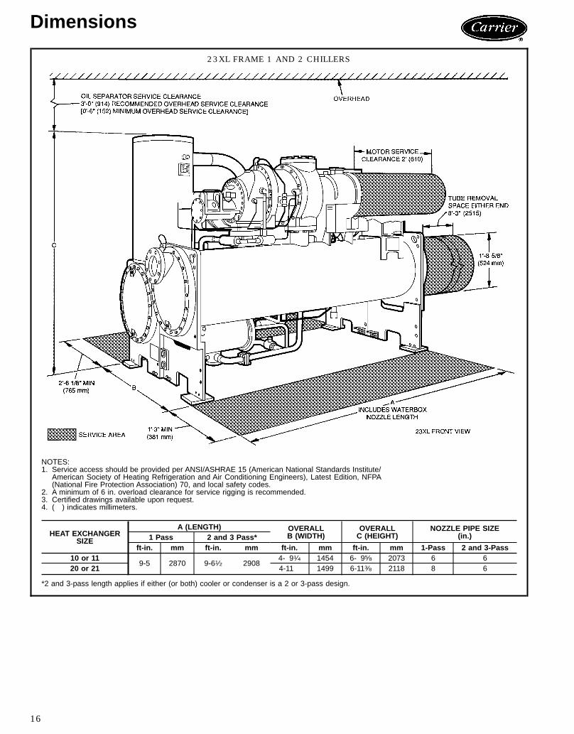
Dimensions
23XL FRAME 1 AND 2 CHILLERS
NOTES:1. Service access should be provided per ANSI/ASHRAE 15 (American National Standards Institute/
American Society of Heating Refrigeration and Air Conditioning Engineers), Latest Edition, NFPA(National Fire Protection Association) 70, and local safety codes.
2. A minimum of 6 in. overload clearance for service rigging is recommended.3. Certified drawings available upon request.4. ( ) indicates millimeters.
HEAT EXCHANGERSIZE
A (LENGTH) OVERALLB (WIDTH)
OVERALLC (HEIGHT)
NOZZLE PIPE SIZE(in.)1 Pass 2 and 3 Pass*
ft-in. mm ft-in. mm ft-in. mm ft-in. mm 1-Pass 2 and 3-Pass10 or 11
9-5 2870 9-61⁄2 29084- 91⁄4 1454 6- 95⁄8 2073 6 6
20 or 21 4-11 1499 6-113⁄8 2118 8 6
*2 and 3-pass length applies if either (or both) cooler or condenser is a 2 or 3-pass design.
16
23XL FRAME 4 CHILLERS
NOTES:1. For flanged waterbox nozzles, refer to the certified drawings for length addition measurements.2. Service access should be provided based on American Society of Heating, Refrigeration, and Air Conditioning Engineers (ASHRAE) 15,
latest edition, National Fire Protection Association (NFPA) 70, and local safety codes.3. A minimum of 6 in. (152 mm) overhead clearance for service rigging is recommended.4. Certified drawings are available upon request.5. ( ) indicates millimeters.
ft-in. mm ft-in. mm ft-in. mm ft-in. mm 1-Pass 2-Pass 3-Pass40-43 13-73⁄4 4159 14-31⁄4 4350 5-107⁄8 1800 7-611⁄16 2303 10 8 6
HEAT EXCHANGER(Cooler and
Condenser Size)
A (Length WithMarine Waterbox — Not Shown)
2 Pass* 1 or 3 Pass†ft-in. mm ft.-in. mm
40-43 14-95⁄8 4512 16-51⁄2 5017
*Assumes both cooler and condenser nozzles on same end of chiller.†1 or 3 pass length applies if either (or both) cooler or condenser is a 1 or 3 pass design.
17
Electrical data
COMPRESSOR MOTORELECTRICAL
CHARACTERISTICS
60 Hz MOTORS 50 Hz MOTORSLow Voltage Low Voltage
Size VI Type Max 208 V 230 V 400 V 460 V 575 V Max 346 V 400 VIkW IkW
LEGENDIkW — Compressor Motor Power Input (Kilowatts)LRA — Locked Rotor AmpsOLTA — Overload Trip Amps (= RLA x 1.08)RLA — Rated Load AmpsVI — Volumetric Index
NOTES:1. Standard Voltages:
60 Hz 50 Hz
Volt For Use onSupply Voltages Volt For Use on
Supply Voltages208/230* 200 to 240 v systems 346 320 to 360 v systems200† 200 to 208 v systems 400 380 to 415 v systems230† 220 to 240 v systems400 360 to 429 v systems460 440 to 480 v systems575 550 to 600 v systems
*Available on Frame 1 and 2 units.†Available on Frame 4 units.
Motor nameplates can be stamped for any voltage within the listedsupply voltage range. Chillers shall not be selected at voltages aboveor below the listed supply voltage range.
2. To establish electrical data for your selected voltage, if other thanlisted voltage, use the following formula:
listed voltageRLA = listed RLA x
selected voltage
listed voltageOLTA = listed OLTA x
selected voltage
selected voltageLRA = listed LRA x
listed voltage
Example: Find the rated load amperage for a 575-v motor listed at1.14 amps per kW input for use at 550 volts.
Compressor motor controllersCompressor motors, controls, and accessories require theuse of starting equipment systems specifically designed for23 Series Chillers. Refer to Carrier Engineering Require-ment Z-375.
Capacitors/power factorsPower factor considerations may indicate use of capacitors.Properly sized capacitors improve power factors, especiallyat part load. Contact your local Carrier sales representativefor further information on power factors.
18
Performance data
Computerized ratingsBecause of the large number of available Carrier 23XL ScrewChiller component combinations and the wide variability inrequired operating conditions, it is impractical to providetabular performance information. Tabulated performanceratings predict ‘‘typical’’ chiller performance. Actual chillerperformance may vary significantly at actual operating con-ditions and as chiller components are optimized around theseconditions.Computerized performance ratings are available through
your local Carrier sales representative. These ratings arecustom matched to meet project-specific operating condi-tions and energy efficiency requirements.
ARI Certification ProgramThe computerized performance ratings of the Carrier 23XLScrew Chiller are certified by the Air Conditioning and Re-frigeration Institute (ARI). The Certification Program re-quires that the manufacturer’s ratings be regularly checkedfor accuracy through a program of chiller testing in strictcompliance with ARI Standard 550. This independent veri-fication provides assurance of chiller performance.
Part-load performanceFrequently, a chiller will operate at part-load for a large ma-jority of its total operating hours. In some cases, a chillerwith better part-load performance will offer an annualizedoperating cost advantage over one which performs less ef-ficiently at lower loads.Established by ARI, the Integrated Part-Load Value (IPLV)
is a weighted average of kW/ton values over a wide rangeof chiller operation. The IPLV provides a convenient methodof comparing the part-load performance of different chill-ers at standardized typical conditions. The IPLV ratingmethodhas been incorporated into the ARI Certification Program.The 23XL Screw Chiller computerized ratings are certifiedin accordance with this program.Variables such as local weather data, building load pro-
files, and local utility rate structures may significantly alterthe impact of part-load performance on actual operatingcost. Any operating cost analysis should include all factorsrelevant to a particular application.
*Flow rates based on standard tubes, cooler, and condenser. Minimumflow based on tube velocity of 3 ft/sec (0.9 m/sec); maximum based on12 ft/sec (3.6 m/sec).
SI METRIC (L/s)
COOLER 1 PASS 2 PASS 3 PASSFrame Size Min Max Min Max Min Max
NOTES:1. Dimensions in ( ) are in millimeters.2. Use grout and package components to establish the level base line.3. If chiller is set on concrete pad, electrical contractor must locate conduit stub-ups outside of pad.
Approximate location shown.
CHILLER FOOTPRINT (FRAME 4 CHILLER)
NOTES:1. Dimensions in ( ) are in millimeters.2. Use grout and package components to establish the level base line.3. If chiller is set on concrete pad, electrical contractor must locate conduit stub-ups outside of pad.
Approximate location shown.
20
STANDARD ISOLATIONVIEW B-B
NOTES:1. Dimensions in ( ) are in millimeters.2. Isolation package includes 4 shear flex pads.
ACCESSORY ISOLATION
HRS — Hot Rolled Steel
NOTES:1. Dimensions in ( ) are in millimeters.2. Accessory (Carrier supplied, field installed) soleplate package in-
cludes 4 soleplates, 16 jacking screws and leveling pads. Re-quires accessory spring vibration isolation package.
3. Jacking screws to be removed after grout has set.4. Thickness of grout will vary depending on the amount necessary
to level chiller. Use only pre-mixed non-shrinking grout, CeilcoteHT-648 or Master Builders 636, 08-11⁄29 (38.1) to 08-21⁄49 (57) thick.
TYPICAL ISOLATION ASSEMBLIES(Isometric View)
21
Application data (cont)
FRAME 1 AND 2 NOZZLE ARRANGEMENTS
COOLER AND CONDENSER NOZZLE ARRANGEMENTS
NOZZLE ARRANGEMENT CODESCooler Condenser
Pass In Out Code Pass In Out Code
11 2 A
111 12 J
2 1 B 12 11 K
23 4 C
213 14 L
5 6 D 15 16 M
37 8 E
317 18 N
9 10 F 19 20 P
WATERBOX NOZZLE SIZES
FRAME PASSNOMINAL PIPE SIZE (in.) ACTUAL PIPE ID (in.)Cooler and Condenser Cooler and Condenser
11 6 6.0652 6 6.0653 6 6.065
21 8 7.9812 6 6.0653 6 6.065
LEGENDID — Inside Diameter
NOTE: All nozzles are nozzle-in-head (NIH) type with 150 psig (1034 kPa) ASA(American Standards Association) flanged connections.
22
FRAME 4 NOZZLE ARRANGEMENTS
COOLER AND CONDENSER NOZZLE ARRANGEMENTS
NOZZLE ARRANGEMENT CODESCooler Condenser
Pass In Out Code Pass In Out Code
18 5 A
111 2 P
5 8 B 2 11 Q
27 9 C
210 12 R
4 6 D 1 3 S
37 6 E
310 3 T
4 9 F 1 12 U
WATERBOX NOZZLE SIZES
FRAME PASSNOMINAL PIPE
SIZE (in.)ACTUAL PIPE
ID (in.)Cooler and Condenser Cooler and Condenser
4*1 10 10.0202 8 7.9813 6 6.065
*Frame 4 waterboxes are factory fabricated with bolt-on covers.
23
Application data (cont)
Vent and drain connectionsAll vents and drain connections are found in the waterboxcovers. Connection size is 3⁄4-in. FPT.Provide high points of the chiller piping system with vents
and the low points with drains. If shut-off valves are pro-vided in the main water pipes near the unit, a minimumamount of system water is lost when the heat exchangersare drained. This reduces the time required for drainage andsaves on the cost of re-treating the system water.It is recommended that pressure gages be provided at
points of entering and leaving water to measure pressuredrop through the heat exchanger. Gages may be installedas shown in Pressure Gage Location table shown below.Pressure gages installed at the vent and drain connectionsdo not include nozzle pressure losses.Use a reliable manometer to measure pressure differen-
tial when determining water flow. Regular gages are insen-sitive and do not provide accurate measurement of flowconditions.
PRESSURE GAGE LOCATION
NUMBEROF PASSES
GAGE LOCATION(Cooler or Condenser)
1, 3 One gage in each waterbox2 Two gages in waterbox with nozzles
Range of applicationThe 23XL refrigeration machines are designed for standardwater chilling 60 Hz applications of 150 to 360 tons (530to 1,270 kW) and 50 Hz applications of 130 to 300 tons(460 to 1,060 kW) using refrigerant HCFC-22. The Frame4 heat exchangers are available with HCFC-22 orHFC-134a.
ASME stampingAll 23XL heat exchangers are constructed in accordancewith American Society of Heating, Refrigeration and AirConditioning Engineers (ASHRAE) 15 Safety Code for Me-chanical Refrigeration (latest edition). This code, in turn,requires conformance with American Society of Mechani-cal Engineers (ASME) Code for Unfired Pressure Vesselswherever applicable.
Relief-valve discharge pipe sizingThe 23XL is equipped with 3 relief valves (1 on the coolerand 2 on the condenser). One additional relief valve (Frame1 and 2 chillers) or 2 relief valves (Frame 4 chillers) are pro-vided on the oil separator when an optional refrigerant iso-lation package is used.
Relief-valve discharge piping sizing should be calculatedper the current version of the ASHRAE 15, latest edition,code using the tabulated C factors for each vessel shownbelow:
*Oil separator relief valve provided with optional refrigerant isolationpackage.
NOTE: Frame 1 and 2 values are for HCFC-22 refrigerant. Frame 4 val-ues are for both HCFC-22 and HFC-134a refrigerant.
Carrier further recommends that an oxygen sensor beinstalled to protect personnel. Sensor should be able to sensethe depletion or displacement of oxygen in the machineroom below 19.5% volume oxygen per ASHRAE 15, lat-est edition.
Design pressuresDesign and test pressures for 23XL heat exchangers arelisted below.
DESIGN AND TEST PRESSURES
PRESSURESSHELL SIDE TUBE SIDE(Refrigerant) (Water)psi kPa psi kPa
Design 300 2068 150 1034Hydrostatic Test — — 225 1551Air Test 375 2586 — —
HEAT EXCHANGER MATERIAL SPECIFICATIONS
ITEM MATERIAL SPECIFICATIONShell HR Steel ASME SA516 GR .70Tube Sheet HR Steel ASME SA516 GR .70Waterbox* Cast Iron ASTM A-48 Class 35Waterbox Cover† HR Steel ASME SA516 GR .70Waterbox Shell† HR Steel ASME SA675 GR .60Tubes Finned Copper ASME SB359Discharge/Suction Steel ASME SA105/SA106
LEGENDASME — American Society of Mechanical EngineersASTM — American Society for Testing and MaterialsHR — Hot Rolled
Factory insulation (optional) — Optional factory insu-lation is available for the evaporator shell and tube sheets,suction pipe, motor end of compressor, economizer, andeconomizer line(s). Insulation applied at the factory is 3⁄4-in.(19.0 mm) thick and has a thermal conductivity K value of0.28 Btu · in./hr · ft2 · °F (0.0404 W/m · °C). Insulationconforms with UL (Underwriters’ Laboratories) Standard 94.Classification 94HBF.Insulation at jobsite — The optional factory insulationpackage provides excellent protection against condensationunder most operating conditions. Use the relative humidityvs dry bulb temperature graph to determine the need foradditional insulation. Plot the relative humidity vs the drybulb temperature. If that point falls above the evaporatorsaturation temperature for your application, additional in-sulation is required. For saturation temperatures other than35 F (2 C) or 45 F (7 C), use interpolation to determineadditional insulation requirements. For example, if an ap-plication has a 35 F (2 C) evaporator saturation tempera-ture, machine room relative humidity of 80%, and dry bulbtemperature of 75 F (24 C), then additional insulation isrequired.
If the machine is to be field insulated, obtain the approxi-mate insulation areas from the Insulation Area drawing onpage 26.Insulation of waterbox covers is made only in the field and
this information is not included in Insulation Requirementstable. When insulating the covers, allow for service accessand removal of covers.
CONDITIONS FOR ONSET OF CONDENSATIONWITH OPTIONAL INSULATION PACKAGE*
90%
80
70
60
50
4070 (21) 75 (24) 80 (27) 85 (29) 90 (32) 95 (35)
DRY BULB TEMPERATURE IN DEGREES F (DEGREES C)
RE
LAT
IVE
HU
MID
ITY
%
45 F (7 C) EVAPORATOR
35 F (2 C) EVAPORATOR
100 (38)
*If the optional insulation package is not used, refer to a psychro-metric chart to determine the onset of condensation.
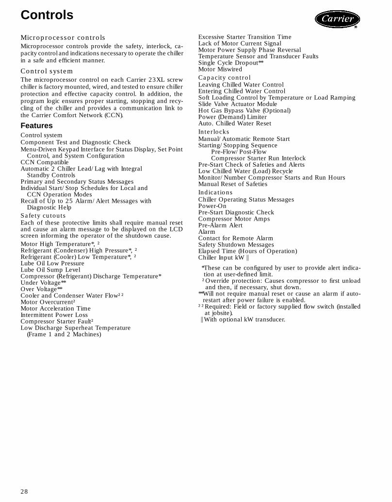
Microprocessor controlsMicroprocessor controls provide the safety, interlock, ca-pacity control and indications necessary to operate the chillerin a safe and efficient manner.
Control systemThe microprocessor control on each Carrier 23XL screwchiller is factory mounted, wired, and tested to ensure chillerprotection and effective capacity control. In addition, theprogram logic ensures proper starting, stopping and recy-cling of the chiller and provides a communication link tothe Carrier Comfort Network (CCN).
FeaturesControl systemComponent Test and Diagnostic CheckMenu-Driven Keypad Interface for Status Display, Set PointControl, and System Configuration
CCN CompatibleAutomatic 2 Chiller Lead/Lag with IntegralStandby Controls
Primary and Secondary Status MessagesIndividual Start/Stop Schedules for Local andCCN Operation Modes
Recall of Up to 25 Alarm/Alert Messages withDiagnostic Help
Safety cutoutsEach of these protective limits shall require manual resetand cause an alarm message to be displayed on the LCDscreen informing the operator of the shutdown cause.Motor High Temperature*, †Refrigerant (Condenser) High Pressure*, †Refrigerant (Cooler) Low Temperature*, †Lube Oil Low PressureLube Oil Sump LevelCompressor (Refrigerant) Discharge Temperature*Under Voltage**Over Voltage**Cooler and Condenser Water Flow††Motor Overcurrent†Motor Acceleration TimeIntermittent Power LossCompressor Starter Fault†Low Discharge Superheat Temperature(Frame 1 and 2 Machines)
Excessive Starter Transition TimeLack of Motor Current SignalMotor Power Supply Phase ReversalTemperature Sensor and Transducer FaultsSingle Cycle Dropout**Motor MiswiredCapacity controlLeaving Chilled Water ControlEntering Chilled Water ControlSoft Loading Control by Temperature or Load RampingSlide Valve Actuator ModuleHot Gas Bypass Valve (Optional)Power (Demand) LimiterAuto. Chilled Water ResetInterlocksManual/Automatic Remote StartStarting/Stopping Sequence
Pre-Flow/Post-FlowCompressor Starter Run Interlock
Pre-Start Check of Safeties and AlertsLow Chilled Water (Load) RecycleMonitor/Number Compressor Starts and Run HoursManual Reset of SafetiesIndicationsChiller Operating Status MessagesPower-OnPre-Start Diagnostic CheckCompressor Motor AmpsPre-Alarm AlertAlarmContact for Remote AlarmSafety Shutdown MessagesElapsed Time (Hours of Operation)Chiller Input kW \
*These can be configured by user to provide alert indica-tion at user-defined limit.†Override protection: Causes compressor to first unloadand then, if necessary, shut down.
**Will not require manual reset or cause an alarm if auto-restart after power failure is enabled.
††Required: Field or factory supplied flow switch (installedat jobsite).
TYPICAL LOCAL INTERFACE DEVICE (LID) DISPLAY SCREENS
Default Display — Displays information most commonly required forchiller operating logs. Two-line system status messages inform theoperator of the operating mode or any alert or alarm messages. Thefour ‘‘softkeys’’ allow access to other control functions.
Status Screens — The Status screens display readings of everypoint monitored by the microprocessor. Cooler, condenser, and oilpressure are included on the Status screens.
30
TYPICAL LOCAL INTERFACE DEVICE (LID) DISPLAY SCREENS (cont)
Schedule Screen — A user established occupancy schedule canbe easily configured for your particular application. A 365-day realtime, battery backed-up clock will automatically start and stop thechiller according to your established schedule or the building’s mas-ter schedule in a CCN system.
Service Screens — The password protected service screens pro-vide the service technician with an array of information to configurethe chiller for your particular application and troubleshoot any prob-lems that may occur.
Set Point Screen — The chilled water, demand limit, and ice buildset points can be entered, stored, viewed, or changed easily fromthis screen.
Alarm History File — TheAlarm History file stores the last 25 alarmsor alerts that have occurred along with the time and date they oc-curred. It allows service technicians to quickly review alarm or alerthistory to identify problems that exist, as well as the actions requiredto resolve the problem.
31
Controls (cont)
TYPICAL LOCAL INTERFACE DEVICE (LID) DISPLAY SCREENS (cont)
The Control Test Screen — This screen allows access to the vari-ous control tests available to the service technician. The techniciancan then quickly identify sources of problems and get the chiller backon line.
The Service Configuration Screens — The Service Configurationscreen allows the service technician to configure the controls for yourparticular application and set the override and alert levels for severalpoints monitored by the control system.
32
Control sequenceTo start: Push Start button — Start initiated; all safetiesare checked to see that they are satisfied (if one is not, anindication of the fault will be displayed and the start aborted).The signal is sent to start the chilled water pump. After5 seconds, the signal is sent to start the condenser waterpump.The microprocessor then puts the start on hold. It checks
if water flows are established. If not satisfied, it will continueto monitor water flows according to the adjustable setting(30 seconds to 5 minutes). If satisfied, it checks the chilledwater temperature against the control point, enables towerfan control, and checks the slide valve decrease timer (toverify that the slide valve is in the unloaded position).If the above checks are satisfied, the microprocessor sends
the signal to start the compressor motor. It monitors themotor acceleration time and if it is excessive, aborts thestart. If the starter fails to transition to run, the start is aborted.Compressor ontime and service ontime start.Once started: Phase reversal conditions are monitored toverify proper rotation of the compressor rotors. The
microprocessor initializes the primary restart protection(15 minutes — start to start). The slide valve opens in a softloading mode and is then transferred to the capacity con-trol mode.To stop: Push Stop button — A signal is sent to deener-gize the compressor motor. Compressor ontime and serviceontime stop. The secondary restart protection (1 minutestop-to-start) is initialized, and the slide valve decrease timeris activated.The microprocessor verifies that power to the compres-
sor is off and, after 30 seconds, sends the signal to deen-ergize the chilled water pump. (If shutdown was caused bythe low load recycle algorithm, the chilled water pump willcontinue to run.) Condenser water pump and tower fan maycontinue to operate if condenser pressure is high.Restart: Restart is permitted after the slide valve timerand the primary and secondary start protection timers haveexpired (a minimum of 15 minutes after the compressorstarts and a minimum of 1 minute after the shutdown isinitiated).
CONTROL SEQUENCE
A — START INITIATED: Pre-start checks are made;chilled water pump started
B — Condenser water pump started (5 secondsafter A)
C — Water flows verified (30 seconds to 5 minutesmaximum)
D — Chilled water temperature checked againstcontrol point; tower fan control enabled; slidevalve decrease timer checked to verify slidevalve position
E — Refrigerant type verified (up to 3 minutesafter D).
F — Compressor motor starts; phase reversal con-ditions monitored; compressor ontime and ser-vice ontime start; 15-minute inhibit timer starts(10 seconds after E)
G — Shutdown initiated: Compressor motor stops;compressor ontime and service ontime stop;1-minute inhibit timer on PSIO Software Version13 and higher; slide valve decrease activatedfor 1 minute
H — Chilled water pump deenergized (30 secondsafter G); condenser pump and tower fan controlmay continue to operate if condenser pressureis high; chilled water pump may continue if inRECYCLE mode
I — Slide valve decrease timer expires (3 minutesafter G)
O/A — Restart permitted (both inhibit timers expired)(minimum of 15 minutes after F; minimum of1 minute after G)
33
Typical piping and wiring
23XL CHILLER WITH FREE-STANDING STARTER
LEGEND1 — Chilled Water Pump Starter2 — Condenser Water Pump Starter3 — Cooling Tower Fan Starter4 — Condenser Water Pump5 — Chilled Water Pump6 — Disconnect7 — Freestanding Compressor Motor Starter8 — Compressor Motor Terminal Box9 — Power Panel (Hidden)10 — Vents
PipingControl WiringPower Wiring
NOTES:1. Wiring and piping shown are for general point-of-connection only and are not
intended to show details for a specific installation. Certified field wiring and di-mensional diagrams are available on request. 23XL chillers should be installedusing certified drawings.
2. All wiring must comply with applicable codes.3. Refer to Carrier System Design Manual for details regarding piping techniques.4. Wiring not shown for optional devices such as:
• remote start/stop• remote alarm• optional safety device• 4 to 20 mA resets• optional remote sensors
34
23XL CHILLER WITH OPTIONAL UNIT-MOUNTED STARTER
LEGEND1 — Chilled Water Pump Starter2 — Condenser Water Pump Starter3 — Cooling Tower Fan Starter4 — Chilled Water Pump5 — Condenser Water Pump6 — Disconnect7 — Vents
PipingControl WiringPower Wiring
NOTES:1. Wiring and piping shown are for general point-of-connection only and are not
intended to show details for a specific installation. Certified field wiring and di-mensional diagrams are available on request. 23XL chillers should be installedusing certified drawings.
2. All wiring must comply with applicable codes.3. Refer to Carrier System Design Manual for details regarding piping techniques.4. Wiring not shown for optional devices such as:
• remote start/stop• remote alarm• optional safety device• 4 to 20 mA resets• optional remote sensors
35
Typical field wiring
23XL TYPICAL FIELD WIRING WITH FREE-STANDING STARTER (FRAME 1 AND 2 CHILLERS)
IMPORTANT: Wiring shown is typical and not intended to show detail for a specificinstallation. Refer to certified field wiring diagrams.
ITEM DESCRIPTION
1
Compressor Motor Starter w/o Integral Disconnector BreakerCompressor Motor Starter w/Integral DisconnectCompressor Motor Starter w/Integral Circuit BreakerCompressor Motor Starter w/High Interrupt CapacityBreaker
Pilot Relays(With two N.O.Contacts Each)See Note 3.5
PR1 (Chilled Water Pump)PR2 (Condenser Water Pump)PR3 (Cooling Tower Fan)PR4 (Shunt Trip Output)PR5 (Alarm Output)
Control Power Transformer (1 KVA)Controls and Oil Heater Circuit BreakerStarter Management Module Package3 Phase Solid-State Motor Overload ProtectionNEMA-1 Starter Enclosure
2 Compressor Motor Starter Branch Disconnect
ITEM DESCRIPTIONA Chilled Water Pump Starter DisconnectB Chilled Water Pump Motor StarterC Condenser Water Pump Starter DisconnectD Condenser Water Pump Motor StarterE Cooling Tower Fan Motor Starter DisconnectF Cooling Tower Fan Motor StarterG Chilled Water Flow Switch (N.O.). See Note 3.1H Condenser Water Flow Switch (N.O.). See Note 3.1J Spare Safety Devices (N.O.). See Note 3.1K Remote Start/Stop Device (N.O.). See Note 3.1L Remote Alarm. See Note 3.3M Remote Annunciator. See Note 3.3N Lug Adapters. See Note 2.1P 6 Lead to 3 Lead Jumpers. (Not shown. See Note 4.0.)Q Lead Connectors. (Not shown. See Note 4.0.)
36
23XL TYPICAL FIELD WIRING WITH FREE-STANDING STARTER (FRAME 1 AND 2 CHILLERS) (cont)
LEGEND
LL — Compressor Motor Starter TerminalsMCM — Thousand Circular MilsNEMA — National Electrical Manufacturer’s AssociationNFPA — National Fire Protection AssociationN.O. — Normally OpenPR — Pilot RelayRLA — Rated Load AmpsT — TerminalTB — Terminal Block
Required Power WiringRequired Control WiringOptions Wiring
NOTES:I. GENERAL1.0 Starters shall be designed and manufactured in accordance
with Carrier Engineering Requirement Z-375.1.1 All field-supplied conductors, devices, field-installation wir-
ing, and termination of conductors and devices, must be incompliance with all applicable codes and job specifications.
1.2 The routing of field-installed conduit and conductors and thelocation of field-installed devicesmust not interfere with equip-ment access or the reading, adjusting, or servicing of anycomponent.
1.3 Equipment, installation, and all starting and control devicesmust comply with details in equipment submittal drawingsand literature.
1.4 Contacts and switches are shown in the position they wouldassumewith the circuit deenergized and the chiller shut down.
1.5 WARNING — Do not use aluminum conductors.1.6 Installer is responsible for any damage caused by improper
wiring between starter and machine.II. POWER WIRING TO STARTER
2.0 Power conductor rating must meet minimum unit nameplatevoltage and compressor motor RLA (rated load amps).When (3) conductors are used:Minimum ampacity per conductor = 1.25 x compressor RLAWhen (6) conductors are used:Minimum ampacity per conductor = 0.721 x compressor RLA
2.1 Lug adapters may be required if installation conditions dic-tate that conductors be sized beyond the minimum ampacityrequired. Contact starter supplier for lug information.
2.2 Compressor motor and controls must be grounded by usingequipment grounding lugs provided inside starter enclosure.
III. CONTROL WIRING3.0 Field supplied control conductors to be at least 18 AWG
(American Wire Gage) or larger.3.1 Chilled water and condenser water flow switch contacts, op-
tional remote start device contacts and optional spare safetydevice contacts, must have 24 vdc rating. Max current is60 ma, nominal current is 10 ma. Switches with gold platedbifurcated contacts are recommended.
3.2 Remove jumper wire between 12A and 12B before connect-ing auxiliary safeties between these terminals.
3.3 Pilot relays can control cooler and condenser pump and towerfan motor contactor coil loads rated 10 amps at 115 vac upto 3 amps at 600 vac. Control wiring required for Carrier tostart pumps and tower fan motors must be provided to as-sure machine protection. If primary pump and tower fan mo-tor control is by other means, also provide a parallel meansfor control by Carrier. Do not use starter control transformeras the power source for pilot relay loads.
3.4 Do not route control wiring carrying 30 v or less within aconduit which has wires carrying 50 v or higher or along sidewires carrying 50 v or higher.
3.5 Voltage selector switch in machine power panel is factoryset for 115 v control power source. When 230 v control powersource is used, set switch to 230 v position.
3.6 Control wiring cables between starter and power panel mustbe shielded with minimum rating of 600 v, 80 C. Ground shieldat starter.
3.7 For 23XL chillers with free-standing starters, voltage to ter-minals LL1 and LL2 comes from a control transformer in astarter built to Carrier specifications. Do not connect an out-side source of control power to the compressor motor starterterminals (LL1 and LL2). An outside power source will pro-duce dangerous voltage at the line side of the starter, be-cause supplying voltage at the transformer secondary ter-minals produces input level voltage at the transformer primaryterminals.
IV. POWER WIRING BETWEEN STARTER AND COMPRESSORMOTOR4.0 Low voltage (600 v or less) compressor motors have (6)
1⁄2 in. terminal studs (lead connectors not supplied byCarrier). Either 3 or 6 leads must be run between compres-sor motor and starter, depending on type of motor starteremployed. If only 3 leads are required, jumper motor termi-nals as follows: 1 to 6, 2 to 4, 3 to 5. Center to center dis-tance between terminals is 2.73 inches. Compressor motorstarter must have nameplate stamped as conforming withCarrier requirement ‘‘Z-375.’’
4.1 When more than one conduit is used to run conductors fromstarter to compressor motor terminal box, one conductor fromeach phase must be in each conduit, to prevent excessiveheating. (e.g., conductors to motor terminals 1, 2, and 3 inone conduit, and those to 4, 5, and 6 in another.)
4.2 Compressor motor power connections can be made throughtop, bottom, or right side of compressor motor terminal boxby rotating the terminal box and using holes cut by contrac-tor to suit conduit. Flexible conduit should be used for thelast few feet to the terminal box for unit vibration isolation.Use of stress cones or 12 conductors larger than 500 MCMmay require an oversize (special) motor terminal box (notsupplied by Carrier). Lead connections between 3-phase mo-tors and their starters must not be insulated until Carrier per-sonnel have checked compressor rotation.
4.3 Compressor motor frame to be grounded in accordance withthe National Electrical Code (NFPA-70) and applicable codes.Means for grounding compressor motor is (2) Thomas andBetts pressure connectors for 350 to 800 MCM wire, sup-plied and located in the back upper and lower right side cor-ners of the compressor motor terminal box.
4.4 Do not allow motor terminals to support weight of wire cables.Use cable supports and strain reliefs as required.
4.5 Use back up wrench when tightening lead connectors tomotor terminal studs. Torque to 10-15 lb-ft max.
37
Typical field wiring (cont)
23XL TYPICAL FIELD WIRING WITH OPTIONAL UNIT-MOUNTED STARTER (FRAME 1 AND 2 CHILLERS)
IMPORTANT: Wiring shown is typical and not intended to show the detail for a specificinstallation. Refer to certified field wiring diagrams.
Pilot Relays(With Two N.O.Contacts Each)See Note 3.3
PR1 (Chilled Water Pump)PR2 (Condenser Water Pump)PR3 (Cooling Tower Fan)PR4 (Shunt Trip Outout)PR5 (Alarm Output)
Control Power Transformer (1 KVA)Controls and Oil Heater Circuit BreakerStarter Management Module PackagePhase Loss/Reversal Imbalance Protection3-Phase Digital AmmeterNEMA-1 Enclosure with Internal Fan Coolingand Lockable Hinged DoorsMicroprocessor-Based Overload Trip ProtectionGround Fault Protection
2 Compressor Motor Starter Branch Disconnect
ITEM DESCRIPTIONA Chilled Water Pump Starter DisconnectB Chilled Water Pump Motor StarterC Condenser Water Pump Starter DisconnectD Condenser Water Pump Motor StarterE Cooling Tower Fan Motor Starter DisconnectF Cooling Tower Fan Motor StarterG Chilled Water Flow Switch (N.O.). See Note 3.1H Condenser Water Flow Switch (N.O.). See Note 3.1J Spare Safety Devices (N.O.). See Note 3.1K Remote Start/Stop Device (N.O.). See Note 3.1L Remote Alarm. See Note 3.3M Remote Annunciator. See Note 3.3N Lug Adapters. See Note 2.1
38
23XL TYPICAL FIELD WIRING WITH OPTIONAL UNIT-MOUNTED STARTER (FRAME 1 AND 2 CHILLERS) (cont)
Required Power WiringRequired Control WiringOptions Wiring
NOTES:I. GENERAL1.0 Starters shall be designed and manufactured in accordance
with Carrier Engineering Requirement Z-375.1.1 All field-supplied conductors, devices, field-installation wir-
ing, and termination of conductors and devices must be incompliance with all applicable codes and job specifications.
1.2 The routing of field-installed conduit and conductors and thelocation of field-installed, devicesmust not interfere with equip-ment access or the reading, adjusting, or servicing of anycomponent.
1.3 Equipment installation and all starting and control devicesmust comply with details in equipment submittal drawingsand literature.
1.4 Contacts and switches are shown in the position they wouldassumewith the circuit deenergized and the chiller shut down.
1.5 WARNING — Do not use aluminum conductors.II. POWER WIRING TO STARTER
2.0 Power conductor rating must meet minimum unit nameplatevoltage and compressor motor RLA (rated load amps).When (3) conductors are used:Minimum ampacity per conductor = 1.25 x compressor RLAWhen (6) conductors are used:Minimum ampacity per conductor = 0.721 x compressor RLA
2.1 Lug adapters may be required if installation conditions dic-tate that conductors be sized beyond the minimum ampacityrequired. Solid-state starters are provided with:A. Two (2) 0-250 MCM lugs provided per phase for power
conductor terminations when compressor motor RLA is400 amps or less.
B. Three (3), 250-500 MCM lugs provided per phase forpower conductor terminations when compressor motorRLA is more than 400 amps.
Wye-Delta starters are provided with:A. Two (2) 250-500 MCM lugs provided per phase for power
conductor terminators when compressor motor RLA is420 amps or less.
B. Two (2) #1-500 MCM lugs provided per phase for powerconductor terminations when compressor motor RLA ismore than 420 amps.
2.2 Power conductors to starter must enter through top of en-closure. Flexible conduit should be used for the last few feetto the enclosure to provide unit vibration isolation.
2.3 Compressor motor and controls must be grounded by usingequipment grounding lugs provided inside starter enclosure.
2.4 Wye-Delta starters require the assembly and the installationof a ‘‘Top Hat’’ (located inside enclosure) to provide the re-quired wire bending space for incoming power leads.
III. CONTROL WIRING3.0 Field supplied control conductors to be at least 18 AWG
(American Wire Gage) or larger.3.1 Chilled water and condenser water flow switch contacts, op-
tional remote start device contacts, and optional spare safetydevice contacts must have 24 vdc rating. Max current is60 mA, nominal current is 10 mA. Switches with gold platedbifurcated contacts are recommended.
3.2 Remove jumper wire between 12A and 12B before connect-ing auxiliary safeties between these terminals.
3.3 Pilot relays can control cooler and condenser pump and towerfan motor contactor coil loads rated 10 amps at 115 vac upto 3 amps at 600 vac. Control wiring required for Carrier tostart pumps and tower fan motors must be provided to as-sure machine protection. If primary pump and tower fan mo-tor control is by other means, also provide a parallel meansfor control by Carrier. Do not use starter control transformeras the power source for pilot relay loads.
3.4 Do not route control wiring carrying 30 v or less within aconduit which has wires carrying 50 v or higher or along sidewires carrying 50 v or higher.
130to300Tons (460 to1060kW)—50HzCarrier Model Number: 23XLPart 1 — General1.01 SYSTEM DESCRIPTIONA. Microprocessor-controlled liquid chiller using a twin
rotor, 3550 rpm (60 Hz) or 2960 rpm (50 Hz), di-rect drive, semi-hermetic, screw compressor using re-frigerant HCFC-22 or HFC-134a. Chillers usingCFC refrigerants such as CFC-11, CFC-12, or CFC/HFC-500 shall not be acceptable.If a manufacturer proposes a liquid chiller usingHCFC-123 refrigerant, then the manufacturer shallinclude in the chiller price:1. A vapor activated alarm system consisting of all
alarms, sensors, safeties, and ventilation equip-ment as required by ANSI/ASHRAE Standard 15Safety Code for Mechanical Refrigeration (latestedition) with the quotation. System shall be ca-pable of responding to HCFC-123 levels of10 ppm Allowable Exposure Limit (AEL).
2. External refrigerant storage tank and pumpout unit.3. High efficiency purge unit.4. Back-up relief valve to rupture disc.5. Chiller pressurizing system to prevent leakage of
non-condensables into chiller during shutdownperiods.
6. Plant room ventilation.1.02 QUALITY ASSURANCEA. Chiller performance shall be rated in accordance with
ARI Standard 550 (latest edition).B. Equipment and installation shall be in compliance with
ANSI/ASHRAE 15 (latest edition).C. Cooler and condenser shall include ASME ‘‘U’’
stamp and nameplate certifying compliance with ASMESection VIII, Division 1 code for unfired pressurevessels.
D. Chiller shall be manufactured in a facility that has beenregistered by UL to the ISO 9000 Series Standardsfor quality.
E. Chiller shall be designed and constructed to meet ULand UL of Canada requirements and shall have labelsappropriately affixed.
F. Each compressor assembly shall undergo a mechani-cal run-in test to check proper operation of compo-nents and to verify that vibration levels, oil pressures/temperatures, and efficiencies are within acceptablelimits. Each compressor assembly shall be pneumati-cally proof tested at 405 psig (2792 kPa) and leaktested with a tracer gas at 225 psig (1551 kPa).
G. Both cooler and condenser shall be proof tested at375 psig (2586 kPa) on the refrigerant side and leaktested with a refrigerant tracer gas at 300 psig(2068 kPa). The water side of each heat exchanger
shall be hydrostatically tested at 1.5 times rated work-ing pressure.
H. The entire chiller assembly shall be leak tested with arefrigerant tracer gas at 300 psig (2068 kPa).
I. Prior to shipment, the chiller automated controls shallbe tested under power to verify proper wiring andensure correct controls operation.
1.03 DELIVERY, STORAGE AND HANDLINGA. Unit shall be stored and handled in accordance with
manufacturer’s instructions.B. Unit shall be shipped with all refrigerant piping and
control wiring factory installed.C. Unit shall be shipped charged with either refrigerant
HCFC-22, refrigerant HFC-134a, or a nitrogen hold-ing charge, and oil as specified on the equipmentschedule.
D. Unit shall be shipped with firmly attached labels thatindicate the name of the manufacturer, chiller modelnumber, chiller serial number, and the refrigerant used.
1.04 WARRANTYWarranty shall include parts and labor for one yearafter start-up or 18 months from shipment, which-ever occurs first.
Part 2 — Products2.01 EQUIPMENTA. General:
Factory assembled, single piece, liquid chiller shall con-sist of compressor, motor, lubrication system, cooler,condenser, initial oil and refrigerant operating charges,microprocessor control system, and documentationrequired prior to start-up. An optional compressor mo-tor starter can be mounted on the chiller, wired, andtested by the chiller manufacturer.
B. Compressor:1. One positive displacement field-serviceable heli-
cal, rotary, semi-hermetic, twin rotor-type com-pressor. Compressor section joints shall be sealedusing O-rings instead of gaskets to reduce the oc-currence of refrigerant leakage.
2. The compressor casing shall be cast-iron with de-sign pressure rating of 300 psig (2068 kPa) orhigher.
3. The compressor/motor shall be designed to op-erate at 3550 rpm (60 Hz) or 2960 rpm (50 Hz)input speed.
4. Bearings shall be pressure lubricated rolling ele-ment type, AFBMA Class 5 or superior.
5. Capacity control shall be via a hydraulically acti-vated slide valve located below rotating screwrotors.
6. Discharge oil separation shall be accomplishedexternal to the compressor casing. Oil separatorand return system shall be designed to ensurethat oil is adequately returned to the compressorand does not collect in the heat exchangers.
40
7. Compressor safeties shall include high compres-sor discharge temperature, high motor windingtemperature, low oil pressure, reverse rotation,and high discharge pressure.
8. Compressor shall be equipped with internal pres-sure relief to protect against overpressure. Forcompressors not equipped with internal pressurerelief, the high side of the chiller shall be pro-tected with an external relief valve capable ofpassing the full load flow produced by thecompressor.
9. Compressor shall be provided with a lubricationsystem to deliver oil under pressure to the bear-ings. System shall consist of:a. Six-micron oil filter with isolation valves toallow filter change without removal of refrig-erant charge.
b. Oil sump heater (115/230 volt, single phase,50 or 60 Hz), if required for proper opera-tion. Heater shall be controlled by unit mi-croprocessor and factory wired.
c. Positive oil flow sensing/verification to occurthrough a float-type oil level sensor used inconjunction with an oil pressure sensor.Systems that rely on a flow switch to moni-tor oil flow can be activated by the flow ofrefrigerant vapor rather than oil and can givean erroneous signal and are thereforeunacceptable.
10. Compressor shall be fully field serviceable. Com-pressors which must be removed and returnedto the factory for service shall not be acceptable.Manufacturer shall sign, on company letterhead,a written statement confirming the ability of thescrew compressor to be field serviced.
11. Acoustical attenuation shall be provided, as re-quired, to achieve a maximum (full load or partload) sound level of [ ] dBA, measured per ARIStandard 575 (latest edition). Attenuation shallbe designed to be easily removed and reinstalled.
C. Motor:1. Compressor motors shall be of the semi-hermetic,
liquid refrigerant cooled, single speed, non-reversing,squirrel cage induction type suitable for the volt-age shown on the equipment schedule.
2. Motors’ design speed shall be 3550 rpm at 60 Hzor 2960 rpm at 50 Hz.
3. Motors shall be suitable for operation in a refrig-erant atmosphere and shall be cooled by atomizedrefrigerant in contact with the motor windings.
4. Motor stator shall be arranged for service or re-moval with only minor compressor disassembly andwithout breaking the main refrigerant pipingconnections.
5. Full load operation of the motor shall not exceednameplate rating.
6. Low-voltage motors (600 v or less) shall be suit-able for connection to wye-delta type reduced in-rush or solid-state type reduced voltage starters.
7. If the mechanical contractor chooses to provide achiller with an open motor instead of the speci-fied semi-hermetic motor, the contractor shalleither:supply additional ventilation to maintain a maxi-mum mechanical room temperature of 104 F(40 C). Additional ventilation requirements shallbe calculated as follows:
(Full load motor kW) (0.05) (3413)CFM =
(104−95) (1.08)
CFM = (FLkW motor) (17.6)
or, if the mechanical room is air conditioned, themechanical contractor shall install additional cool-ing equipment to dissipate the motor heat as perthe following formula:
BTUH = (FLkW motor) (0.05) (3413)
BTUH = (FLkW motor) (171)
and, alternately
BTUHTONS =
12,000
In either case, the additional piping, valves, air-handling equipment, insulation, wiring, switch-gear changes, ductwork, and coordination withother trades shall be the responsibility of the me-chanical contractor. Shop drawings reflecting anychanges to the design shall be included in the sub-mittal and incorporated into the final as-built draw-ings for the project.Also, if an open motor is provided, a mechanicalroom thermostat shall be installed and set at104 F (40 C). If this temperature is exceeded, thechillers shall shut down and an alarm signal shallbe generated to the central Energy ManagementSystem (EMS) display module prompting the ser-vice personnel to diagnose and repair the causeof the over-temperature condition. The mechani-cal contractor shall be responsible for all changesto the design, including coordination with tem-perature control, electrical, and other trades.In addition, the electrical power consumption ofany auxiliary ventilation and/or mechanical cool-ing required to maintain mechanical room condi-tions as stated above shall be considered in thedetermination of conformance to the scheduledchiller energy efficiency requirement.
D. Cooler and Condenser:1. Cooler and condenser shall be of shell and tube
type construction, each in separate shells. Unitsshall be fabricated with high-performance tub-ing, steel shell and tube sheets. Waterboxes shallbe nozzle-in-head type with nozzles either flangedor with Victaulic grooves to allow for use ofVictaulic couplings.
41
Guide specifications (cont)
2. Tubing shall be copper, high-efficiency type, withintegral internal and external enhancement. Tubesshall be nominal 3⁄4-in. OD with standard wallthickness of 0.025 in. measured at the root ofthe fin. Tubes shall be rolled into tube sheets andshall be individually replaceable. Tube sheet holesshall be double grooved for joint structural integ-rity. Intermediate support sheet spacing shall notexceed 36 inches.
3. Waterboxes and nozzle connections shall be de-signed for 150 or 300 psig (1034 or 2068 kPa)maximum working pressure.
4. The tube sheets of the cooler and condenser shallbe bolted together to allow for field disassemblyand reassembly.
5. Cooler and condenser shall display ASME name-plates that show pressure and temperature dataand the ‘‘U’’ stamp for ASME Section VIII,Division 1.
6. Waterboxes shall have vents, drains, and coversto permit tube cleaning within the space shownon the drawings. A thermistor type temperaturesensor shall be factory installed in each waternozzle.
7. Cooler shall be designed to prevent liquid refrig-erant from entering the compressor. Devices thatintroduce pressure losses (such as mist elimina-tors) shall not be acceptable because they are sub-ject to structural failures that can result in exten-sive compressor damage.
8. Tubes shall be individually replaceable from ei-ther end of the heat exchanger without affectingthe strength and durability of the tube sheet andwithout causing leakage in adjacent tubes.
9. The condenser shell shall include an external ther-mal economizer that cools the condensed liquidrefrigerant to a reduced temperature, thereby in-creasing the refrigeration cycle efficiency.
10. An optional refrigerant isolation valve packageshall be factory installed to allow isolation of therefrigerant charge in the cooler or condenser.
E. Refrigerant Flow Control:Liquid refrigerant from the condenser shall be me-tered using a direct acting, float-type metering valveto maintain the proper liquid level of refrigerant in theheat exchangers under both full and part load oper-ating conditions. By maintaining a liquid seal at theflow valve, bypassed hot gas from the condenser tothe cooler (which decreases cycle efficiency) is elimi-nated. The float valve chamber shall have a boltedaccess cover to allow field inspection, and the floatvalve shall be field serviceable. Fixed orifices shall notbe acceptable.
F. Controls, Safeties, and Diagnostics:1. Controls:
a. The chiller shall be provided with a factoryinstalled and wired microprocessor controlsystem with individually replaceable modularcomponent construction. Components
included shall be the main processor/input-output module, power supply, starter man-agement module (located in the starter cabi-net), relay board, temperature (thermistor) andpressure (transducer) sensors, and all neces-sary auxiliary devices required for proper opera-tion. An optional input module (8 input chan-nels) can be factory or field installed. The con-trol center includes a 16-line by 40-characterliquid crystal display, 4 function keys (soft-keys), stop button, and alarm light. The mi-croprocessor can be configured for eitherEnglish or SI units. Controls shall be pro-vided with a battery backup to prevent theloss of configuration information in case ofpower failure.The chiller control system shall have the abil-ity to interface and communicate directly tothe building control system without the useof additional field-installed hardware or soft-ware. Additional hardware shall be necessaryif the building control system is not part of aCarrier Comfort Network (CCN).The default standard display screen shallsimultaneously indicate the followinginformation:• Date and time of day• 24-character primary system statusmessage
• 24-character error message• Chiller operating hours• Entering chilled water temperature• Leaving chilled water temperature• Evaporator refrigerant temperature• Entering condenser water temperature• Leaving condenser water temperature• Condenser refrigerant temperature• Oil supply pressure differential• Oil sump temperature• Percent motor Rated Load Amps (RLA)
The default screen shall be displayed if thereis no manual activity at the control consolefor 15 minutes. The 4 function keys shall besoftware driven within the Status, Schedule,Set Point and Service menu structures (as de-scribed in section k).
b. Capacity control shall be by means of a hy-draulically operated slide valve under the com-pressor rotors. Load modulation shall be from100% to 20% of compressor full load undernormal ARI conditions without the use of hotgas bypass. The slide valve shall be preciselypositioned by a PID (proportional-integral-derivative) control algorithm to ensure pre-cise control (± .5 F [.3 C]) of desired chilledwater temperature without hunting or over-shooting the set point.
c. The microprocessor control system shall au-tomatically control the chilled water pump andcondenser water pump.
42
d. Upon request to start the compressor, the con-trol system shall start the chilled water pump,condenser water pumps, and tower fans, ifappropriate, and verify that flows have beenestablished. The controller shall then com-pare the entering/leaving chilled water tem-perature with the chilled water set point. Ifthe chilled water temperature is less than thechilled water set point plus a specified dead-band, the control system will shut down thecondenser water pump and tower fans andwait for the cooling load to be established.
e. A user-configurable ramp loading rate, effec-tive during the chilled water temperature pull-down period, shall control the rate of slidevalve opening to prevent a rapid increase incompressor power consumption. The con-trols shall allow configuration of the ramploading rate in either degrees/minute of chilledwater temperature pulldown or percent mo-tor amps/minute. During the ramp loadingperiod, a message shall be displayed inform-ing the operator that the chiller is operatingin ramp loading mode.
f. The chiller controls shall be supplied as stan-dard with a two chiller lead/lag and a thirdchiller standby system. The control systemshall automatically start and stop a lag or sec-ond chiller on a two chiller system. If one ofthe two chillers on line goes into fault mode,the third or standby chiller shall be controlledas a lag chiller. The two chiller lead/lag sys-tem shall allow manual rotation of the leadchiller and a staggered restart of the chillersafter a power failure. Sequencing shall bebased on leaving or entering chiller watertemperature.
g. The control system shall include compressorruntime timers to protect themotor from rapidcycling (a 15-minute minimum start-to-starttimer and a 1-minute minimum stop-to-starttimer). In addition, the compressor will be in-hibited from restarting if more than 8 manualstarts within a 12-hour period have occurred.
h. The control system shall automatically shutdown the compressor to minimize energy us-age whenever the leaving chilled water tem-perature is 5 F (3 C) below the desired chilledwater set point or the chilled water tempera-ture is below its set point and the chilled wa-ter temperature difference is less than a speci-fied value. The chilled water pump will re-main on, and when the leaving chilled watertemperature rises above the set point by auser-configured amount, the compressor shallautomatically restart. During the shutdown pe-riod, a message shall be displayed informingthe operator a recycle restart is pending.
i. The control center shall monitor line voltage,and if loss of voltage, high or low line volt-age, or single cycle dropout is sensed, thechiller shall shut down. Upon restoration of
line voltage, if the auto-restart after powerfailure algorithm is enabled, the chiller shallautomatically resume the mode of operationprior to shutdown.
j. The control system shall allow configurationof reset of the chilled water temperature setpoint based on any one of the followingcriteria:• Chilled water reset based on water tem-perature rise across the evaporator.
• Chilled water reset based on an external4-20 mA signal.
• Chilled water reset based on a remote tem-perature sensor (such as outdoor air).
When reset is active, a message shall be dis-played indicating the type of reset in effect.
k. The control center shall limit amp draw ofthe compressor to the rated load amps (RLA)or to a lower value (ranging from 40% to100%) of compressor RLA. The control cen-ter shall allow configuration of demand limitbased on either a user input or an external4-20 mA signal. When demand limit is ac-tive, a message shall be displayed indicatingthe source of the demand signal.
STATUS FUNCTIONIn addition to the default screen, status screensshall be accessible to view the status of everypoint monitored by the control centerincluding:
• Evaporator pressure• Condenser pressure• Compressor discharge temperature• Motor winding temperature• Number of compressor starts• Control point settings• Discrete output status of various devices• Compressor motor starter status• Optional spare input channels (16maximum)
SCHEDULE FUNCTIONThe chiller controls shall be configurable formanual or automatic start-up and shutdown.In automatic operation mode, the controlsshall be capable of automatically starting andstopping the chiller according to a stored userprogrammable occupancy schedule. The con-trols shall include built-in provisions for ac-cepting a minimum of three, 365-day occu-pancy schedules, (the local time schedule shallbe Schedule 01, the ice build time scheduleshall be Schedule 02, and the CCN defaultschedule shall be 03). Each schedule shall al-low a minimum of 8 separate occupied, un-occupied periods. All of the 8 occupied pe-riods can be scheduled by individual day forany day of the week. A separate schedule shallbe provided for holidays. Schedules shall al-low specifications of Daylight Savings start/end and up to 18 user-defined holidays up to
43
Guide specifications (cont)
one year in advance (month, day, and dura-tion of days). Display of the occupancy sched-ules shall be viewable on the LCD screen.Each schedule shall provide a means of con-figuring an occupancy time override to per-mit a ‘‘one time extension’’ of an occupiedperiod on the configured day. The controlsshall also provide for chiller start-up and shut-down through a remote contact closure froma customer supplied device or from a build-ing management system software command.
SETPOINT FUNCTIONThe controls shall provide the capability toview and change the leaving chilled water setpoint, entering chilled water set point, de-mand limit set point, or ice build set point atany time during chiller operation or shut-down periods. The controls shall allow for thespecification of capability control through ei-ther leaving chilled water or entering chilledwater.
SERVICE FUNCTION
The controls shall provide a password pro-tected service function which allows autho-rized individuals to:
• View the alarm history file which containsthe last 25 alarm/alert messages with timeand date stamp. These messages shall bedisplayed in text form, not in codes.
• Execute the chiller Control Test functionfor quick identification of malfunctioningcomponents
• View, modify, and/or configure systemsand controls options, capacity and safetyoverride limits and parameters.
• View/modify chiller occupancy periods• View/modify schedule holiday periods• View/modify schedule override periods• View/modify system time and date• Specify a network address• Change units display on the LID
2. Safeties:a. Unit shall automatically shut down when any
of the following conditions occurs (Each ofthese protective limits shall require manualreset and cause an alarm message to be dis-played on the LCD screen informing the op-erator of the shutdown cause.):1) Motor overcurrent2) Over voltage*3) Under voltage*4) Single cycle dropout*5) Low evaporator refrigerant temperature6) High condenser pressure7) High motor temperature8) High compressor discharge temperature9) Low oil pressure10) Low oil level11) Loss of cooler water flow12) Loss of condenser water flow
13) Starter fault14) High oil filter differential pressure15) Low discharge superheat temperature
(Frame 1 and 2 chillers)16) Out-of-range sensors17) Excessive starter transition time18) Motor current signal loss19) Motor power supply phase reversal20) Temperature sensor and transducer faults21) Single cycle dropout22) Motor running in reverse (miswired)23) Motor running without control
authorization
*Will not require manual reset or cause analarm if auto-restart after power failure isenabled.
b. The control system shall detect conditions thatapproach protective limits and shall take self-corrective action prior to an alarm occurring.The system shall automatically reduce chillercapacity when any of the following are outof normal operating range:
• High condenser pressure• High motor temperature• Low evaporator refrigerant temperature• High motor amps
During the capacity override period, a pre-alarm (alert) message shall be displayed in-forming the operator which condition is caus-ing the capacity override. Once the conditionis again within acceptable limits, the overridecondition shall terminate and the chiller shallrevert to normal chilled water control. If dur-ing either condition the protective limit isreached, the chiller will shut down, an alarmshall be generated, and a text message willbe displayed informing the operator whichcondition caused the shutdown and alarm.
3. Diagnostics and Service:a. The control system shall execute a series of
pre-start checks whenever a start commandis received to determine if pressures, tem-peratures, and timers are within pre-start lim-its, thereby allowing start-up to proceed. Ifany of the limits are exceeded, a text alertmessage will be displayed informing the op-erator of the cause of the pre-start alert.
b. A self-diagnostic control test shall be an in-tegral part of the control system to allow quickidentification of abnormal system conditionsandmalfunctioning chiller components. Oncethe controls test has been initiated, all pres-sure and temperature sensors shall be checkedto ensure they are within their normal oper-ating range. A pump test shall automaticallyenergize the chilled water and condenser wa-ter pumps. The control system shall confirmthat water flows have been established andrequire operator confirmation prior to pro-ceeding to the next test.
44
c. A slide valve test shall energize the increaseand decrease slide valve solenoids to checkfor proper operation. The controls shall re-questmanual operation confirmation of propersolenoid operation before proceeding to thenext test.
d. In addition to a comprehensive automatedControl Test, the controls shall provide amanual option that permits selection and test-ing of individual control components and in-puts. A thermistor test and transducer testshall display the actual reading of each trans-ducer and each thermistor installed on thechiller on the LCD screen.
e. All sensors shall have quick disconnects toallow replacement of the sensor without re-placement of the entire sensor wire. Pressuretransducers shall be capable of field calibra-tion to ensure accurate readings and to avoidunnecessary transducer replacement. Trans-ducers shall be serviceable without the needfor refrigerant charge removal or isolation.
4. Building Control System Interface:The chiller control system shall have the ability tointerface and communicate directly to the build-ing control system without the use of additionalfield installed hardware and software. If differentbuilding control and chiller suppliers are chosen,the chiller shall be supplied with a dataport mod-ule which shall translate the information in thechiller microprocessor to an ASCII stream of datawhich can be read by any manufacturer’s buildingmanagement control system.
G. Low Voltage Unit Mounted Starter:An optional reduced voltage wye-delta or solid-statestarter shall be supplied. The compressor motor-startershall be factory mounted, wired, and tested prior toshipment by the chiller manufacturer. Customer elec-trical connection for compressor motor power shallbe limited to main starter power connection only.Solid-state starter shall provide stepless compressormotor accelerating and limit motor inrush current to100-600% of compressor motor RLA. The startershall include 6 silicon control rectifiers (SCR) withintegrally-mounted bypass contactors to provide SCRbypass once the motor has achieved full voltage andspeed. The starter shall also include automatic accel-eration kick circuitry which monitors motor currentto sense when the inrush current subsides and auto-matically ramps voltage up at a faster rate to elimi-nate the instability that occurs at the breakaway torquepoint. Starter shall be UL and CSA approved and shallinclude:• NEMA 1 enclosure with integral fan cooling andlockable hinged doors
• 1 KVA control/oil heater transformer with branchcircuit breaker
• 5 pilot relays for control of chilled water pump, con-denser water pump, tower fan, customer remotealarm, shunt trip, and main power disconnect. Theshunt trip shall be energized by the SMM (Starter
Management Module) during unauthorized opera-tion (such as loss of communication between theSMM and PSIO [Processor Sensor Input/OutputModule]).
• Microprocessor based overload trip protection• Phase loss/reversal/imbalance protection• Ground fault protection• Three-phase digital ammeter• Main power disconnect (non-fused type) with shunttrip.
Solid-state starters also include the following standardfeatures:• Normal interrupt capacity main circuit breaker withshunt trip
• Phase loss/reversal/imbalance protection• Integral SCR bypass contactors• Three-phase digital voltmeter• Three-phase over/under voltage protection• Digital power factor display• Digital frequency display• Event history file to store last 99 events (start,stopfault)
H. Electrical Requirements:1. Electrical contractor shall supply and install main
electrical power line, disconnect switches, circuitbreakers, electrical protection devices per local coderequirements and as indicated necessary by thechiller manufacturer.
2. Electrical contractor shall wire thewater flow switchesto the chiller control circuit to ensure that chillerwill not operate until flows are established andmaintained.
3. Electrical contractor shall wire the chilled waterpump, condenser water pump, and tower fan con-trol circuit to the chiller control circuit.
4. Electrical contractor shall supply and install elec-trical wiring and devices required to interface thechiller controls with the building control system, ifapplicable.
5. Electrical power shall be supplied to the unit at thevoltage, phase, and frequency listed in the equip-ment schedule.
I. Piping Requirements— Instrumentation and Safeties:1. Mechanical contractor shall supply and install pres-
sure gages in readily accessible locations in pipingadjacent to the chiller such that they can be easilyread from a standing position on the floor. Gagesshall be Marsh Master or equal with 41⁄2-in. nomi-nal diameter face. Scale range shall be such thatdesign values shall be indicated at approximatelymid-scale.Gages shall be installed in the entering and leav-ing water lines of the cooler and condenser.
2. Mechanical contractor shall supply and install flowdetection devices in chilled water and condenserwater piping. Switches shall make contact whenflow is established. Flow switches shall be installedin horizontal runs at least 5 pipe diameters down-stream from any bend or tee.
45
Guide specifications (cont)
J. Insulation:1. Chilled water piping and cooler waterboxes shall
be insulated by the mechanical contractor.2. Factory installed insulation shall be available for
the chiller. Additional insulation shall be installedat the jobsite by the mechanical contractor.
3. Chiller insulation shall be 3⁄4-in. thick and shall havea thermal conductivity not exceeding 0.28 Btu •in./hr • sq ft • F and shall conform to UL Stand-ard 94, Classification 94 HBF.
K. Vibration Isolation:Chiller manufacturer shall furnish neoprene isolatorpads for mounting equipment on a level concretesurface.
L. Start-Up:1. The chiller manufacturer shall provide a factory-
trained representative, employed by the chillermanufacturer, to perform the start-up proceduresas outlined in the start-up, operation, andmaintenance manual provided by the chillermanufacturer.
2. After the above services have been performed, thesame factory-trained representative shall be avail-able for a period of classroom instruction (not toexceed 4 hours) to instruct the chiller owner’s per-sonnel in the proper operation and maintenanceof the chiller.
3. Manufacturer shall supply the following literature:a. Start-Up, Operation, and Maintenance
Instructions.b. Installation Instructions.c. Field Wiring Diagrams.d. One complete set of certified drawings.
M. Optional Field Installed Accessories:
The following standard accessories are available forfield installation:1. Soleplate Package2. Spring Isolators
3. Spare Sensor Package4. Control Options Module Upgrade Kit5. Stand-Alone Pumpout Unit6. Separate Storage Tank and Pumpout Unit7. Flow Switch, Differential Pressure Type8. Sound Insulation Kit9. Refrigerant Isolation Package10. Automatic Hot Gas Bypass11. Low Voltage Unit-Mounted Starter (Wye-Delta,
Solid State)12. Low Voltage Remote Motor Starter (Wye-Delta,
Solid State)13. Field Mounting Kit for Unit-Mounted Starters
N. Factory Installed Options:1. Thermal Insulation2. Automatic Hot Gas Bypass3. Control Options Module4. Cooler/Condenser Tubing Options5. Cooler and Condenser Passes6. Nozzle-In-HeadWaterboxes, 300 psig (2067 kPa)