14
© 2017 Nokia 1 Carrier Aggregation and Dual Connectivity Rapeepat Ratasuk and Amitava Ghosh Mobile Radio Research Lab, Nokia Bell Labs ISART 2017
© 2017 Nokia1
Carrier Aggregation and Dual Connectivity
Rapeepat Ratasuk and Amitava Ghosh
Mobile Radio Research Lab, Nokia Bell Labs
ISART 2017
2
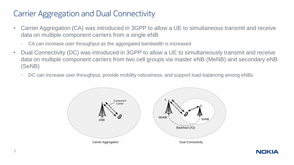
• Carrier Aggregation (CA) was introduced in 3GPP to allow a UE to simultaneous transmit and receive
data on multiple component carriers from a single eNB
- CA can increase user throughput as the aggregated bandwidth is increased
• Dual Connectivity (DC) was introduced in 3GPP to allow a UE to simultaneously transmit and receive
data on multiple component carriers from two cell groups via master eNB (MeNB) and secondary eNB
(SeNB)
- DC can increase user throughput, provide mobility robustness, and support load-balancing among eNBs
Carrier Aggregation and Dual Connectivity
SeNB
f1
Control
Data
Data
MeNB
f2
Backhaul (X2)
Dual Connectivity
f1f2
eNB
Carrier Aggregation
Component
Carrier
3
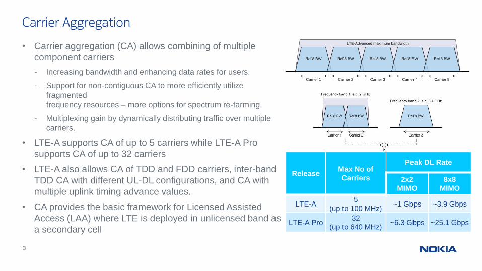
• Carrier aggregation (CA) allows combining of multiple
component carriers
- Increasing bandwidth and enhancing data rates for users.
- Support for non-contiguous CA to more efficiently utilize
fragmented
frequency resources – more options for spectrum re-farming.
- Multiplexing gain by dynamically distributing traffic over multiple
carriers.
• LTE-A supports CA of up to 5 carriers while LTE-A Pro
supports CA of up to 32 carriers
• LTE-A also allows CA of TDD and FDD carriers, inter-band
TDD CA with different UL-DL configurations, and CA with
multiple uplink timing advance values.
• CA provides the basic framework for Licensed Assisted
Access (LAA) where LTE is deployed in unlicensed band as
a secondary cell
Carrier Aggregation
LTE-Advanced maximum bandwidth
Carrier 1 Carrier 4 Carrier 5Carrier 3Carrier 2
Rel’8 BW Rel’8 BW Rel’8 BW Rel’8 BW Rel’8 BW
ReleaseMax No of
Carriers
Peak DL Rate
2x2
MIMO
8x8
MIMO
LTE-A5
(up to 100 MHz)~1 Gbps ~3.9 Gbps
LTE-A Pro32
(up to 640 MHz)~6.3 Gbps ~25.1 Gbps
© 2017 Nokia4
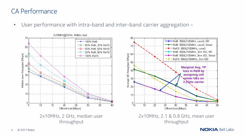
CA Performance
• User performance with intra-band and inter-band carrier aggregation –
Marginal Avg. TP
loss in Rel8 by
assigning cell
center UEs on
2.1GHz carrier
2x10MHz, 2 GHz, median user throughput
2x10MHz, 2.1 & 0.8 GHz, mean user throughput
© 2017 Nokia5
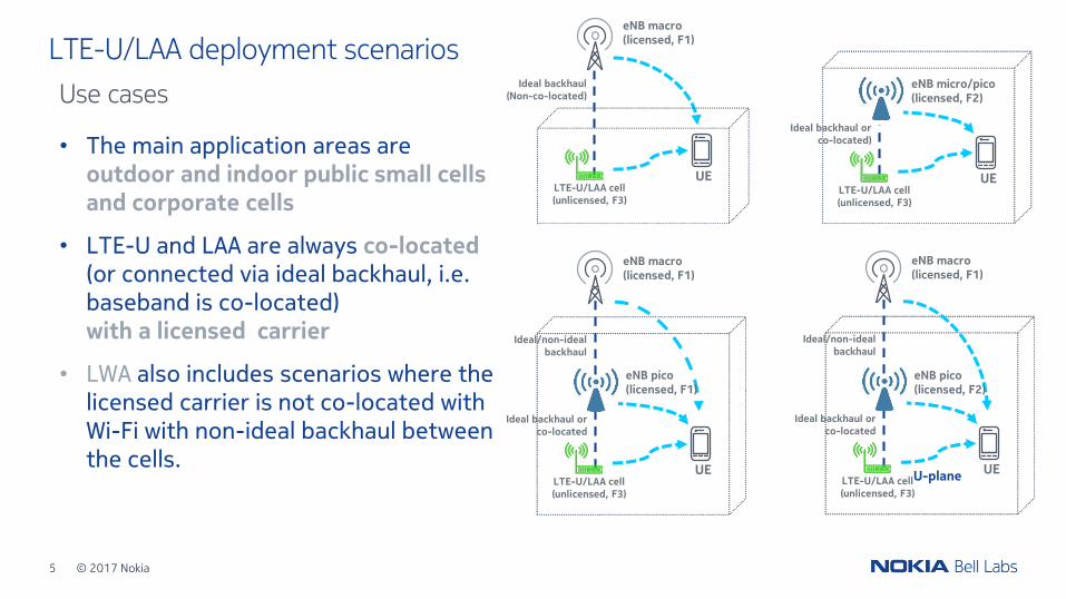
• The main application areas are outdoor and indoor public small cells and corporate cells
• LTE-U and LAA are always co-located(or connected via ideal backhaul, i.e. baseband is co-located)with a licensed carrier
• LWA also includes scenarios where the licensed carrier is not co-located with Wi-Fi with non-ideal backhaul between the cells.
LTE-U/LAA deployment scenarios
Use cases
eNB macro (licensed, F1)
LTE-U/LAA cell(unlicensed, F3)
UE
Ideal backhaul(Non-co-located)
eNB micro/pico (licensed, F2)
LTE-U/LAA cell(unlicensed, F3)
UE
Ideal backhaul or co-located)
eNB macro (licensed, F1)
Ideal/non-ideal backhaul
LTE-U/LAA cell(unlicensed, F3)
UE
Ideal backhaul or co-located
eNB macro (licensed, F1)
Ideal/non-ideal backhaul
LTE-U/LAA cell(unlicensed, F3)
UEU-plane
Ideal backhaul or co-located
eNB pico (licensed, F2)
eNB pico (licensed, F1)
© 2017 Nokia6
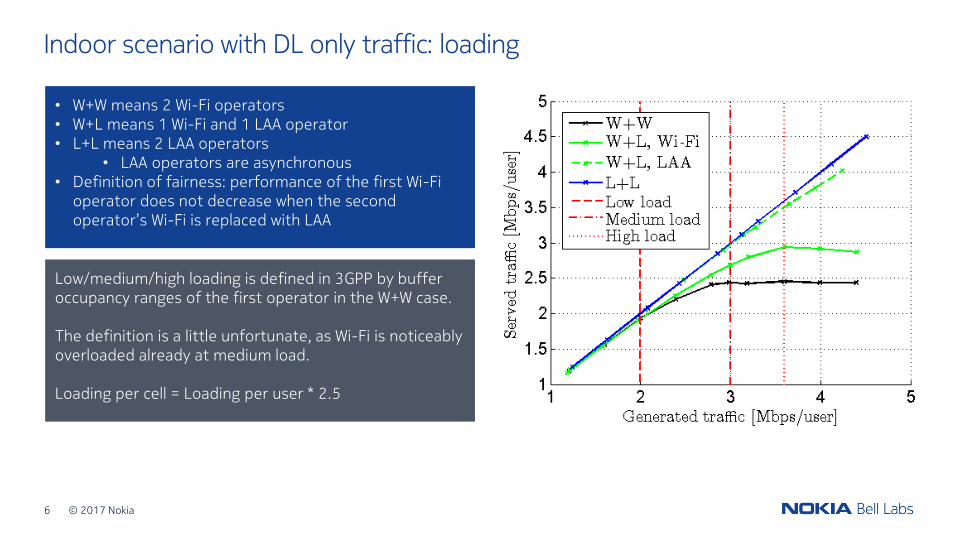
Indoor scenario with DL only traffic: loading
• W+W means 2 Wi-Fi operators• W+L means 1 Wi-Fi and 1 LAA operator• L+L means 2 LAA operators
• LAA operators are asynchronous• Definition of fairness: performance of the first Wi-Fi
operator does not decrease when the second operator’s Wi-Fi is replaced with LAA
Low/medium/high loading is defined in 3GPP by buffer occupancy ranges of the first operator in the W+W case.
The definition is a little unfortunate, as Wi-Fi is noticeably overloaded already at medium load.
Loading per cell = Loading per user * 2.5
© 2017 Nokia7
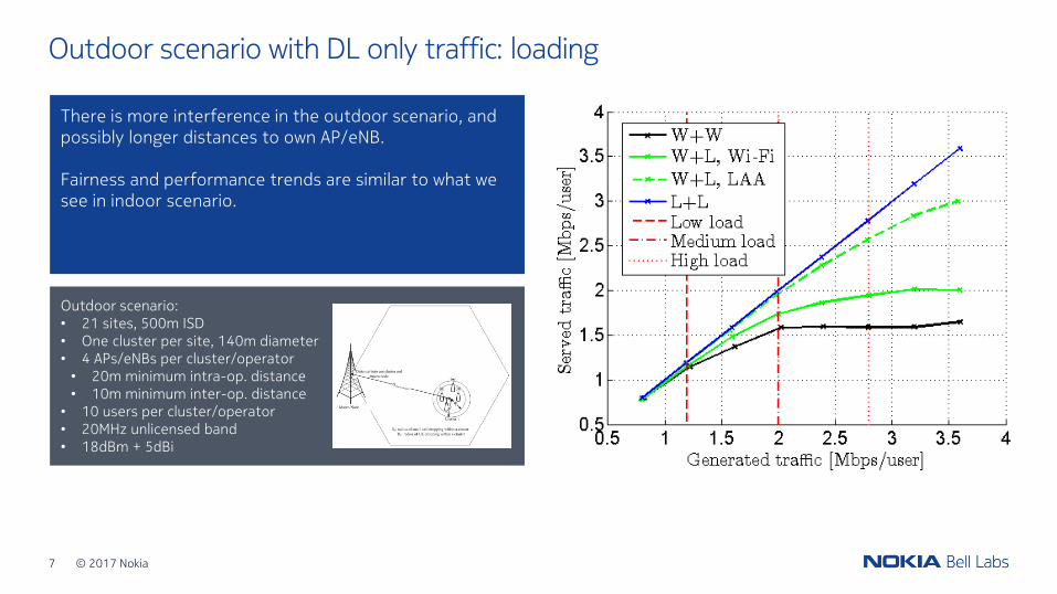
Outdoor scenario with DL only traffic: loading
There is more interference in the outdoor scenario, and possibly longer distances to own AP/eNB.
Fairness and performance trends are similar to what we see in indoor scenario.
Outdoor scenario:
• 21 sites, 500m ISD
• One cluster per site
• 140m cluster diameter
• 4 APs/eNBs per cluster/operator
• 10 users per cluster/operator
• 20MHz unlicensed band
• 18dBm + 5dBi
Outdoor scenario:• 21 sites, 500m ISD• One cluster per site, 140m diameter• 4 APs/eNBs per cluster/operator• 20m minimum intra-op. distance• 10m minimum inter-op. distance
• 10 users per cluster/operator• 20MHz unlicensed band• 18dBm + 5dBi
8
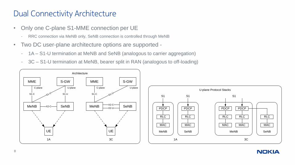
• Only one C-plane S1-MME connection per UE
- RRC connection via MeNB only, SeNB connection is controlled through MeNB
• Two DC user-plane architecture options are supported -
- 1A – S1-U termination at MeNB and SeNB (analogous to carrier aggregation)
- 3C – S1-U termination at MeNB, bearer split in RAN (analogous to off-loading)
Dual Connectivity Architecture
MME
MeNB
S-GW
SeNB
S1-C
X2-C
UE
S1-US1-U
1A
MME
MeNB
S-GW
SeNB
S1-C
X2-U
UE
S1-U
3C
X2-C
PDCP
RLC
MAC
MeNB
S1
PDCP
RLC
MAC
SeNB
S1
PDCP
RLC
MAC
MeNB
S1
RLC
MAC
SeNB
PDCP
RLC
MAC
Architecture
1A 3C
U-plane Protocol StacksC-plane U-plane U-planeC-plane
9
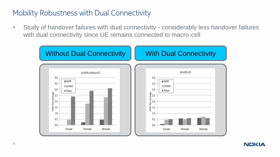
Mobility Robustness with Dual Connectivity
• Study of handover failures with dual connectivity - considerably less handover failures
with dual connectivity since UE remains connected to macro-cell
0.0
0.5
1.0
1.5
2.0
2.5
3.0
3.5
4.0
3 kmph 30 kmph 60 kmph
HO
F P
erc
en
tag
e
(a) HOFs without DC
3GPP
London
Tokyo
0.0
0.5
1.0
1.5
2.0
2.5
3.0
3.5
4.0
3 kmph 30 kmph 60 kmph
HO
F P
erc
en
tag
e
(b) HOFs DC
3GPP
London
Tokyo
0.0
0.5
1.0
1.5
2.0
2.5
3.0
3.5
4.0
3 kmph 30 kmph 60 kmph
HO
F P
erc
en
tag
e
(a) HOFs W/O DC
3GPP
London
Tokyo
0.0
0.5
1.0
1.5
2.0
2.5
3.0
3.5
4.0
3 kmph 30 kmph 60 kmph
HO
F P
erc
en
tag
e
(a) HOFs without DC
3GPP
London
Tokyo
0.0
0.5
1.0
1.5
2.0
2.5
3.0
3.5
4.0
3 kmph 30 kmph 60 kmph
HO
F P
erc
en
tag
e
(b) HOFs DC
3GPP
London
Tokyo
0.0
0.5
1.0
1.5
2.0
2.5
3.0
3.5
4.0
3 kmph 30 kmph 60 kmphH
OF
Pe
rce
nta
ge
(a) HOFs W/O DC
3GPP
London
Tokyo
Without Dual Connectivity With Dual Connectivity
10
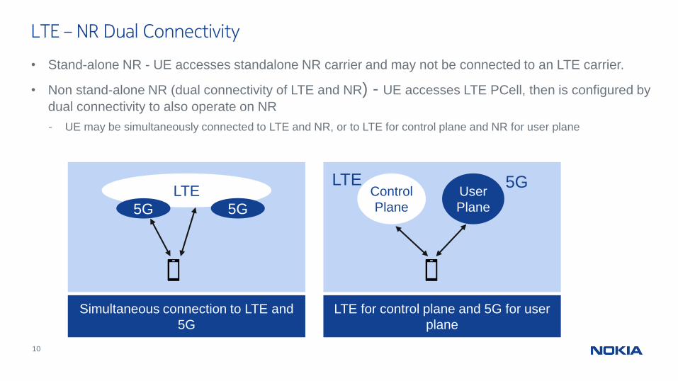
• Stand-alone NR - UE accesses standalone NR carrier and may not be connected to an LTE carrier.
• Non stand-alone NR (dual connectivity of LTE and NR) - UE accesses LTE PCell, then is configured by
dual connectivity to also operate on NR
- UE may be simultaneously connected to LTE and NR, or to LTE for control plane and NR for user plane
LTE – NR Dual Connectivity
LTE for control plane and 5G for user
plane
Control
Plane
User
Plane
Simultaneous connection to LTE and
5G
LTE
5G 5G
LTE 5G
11
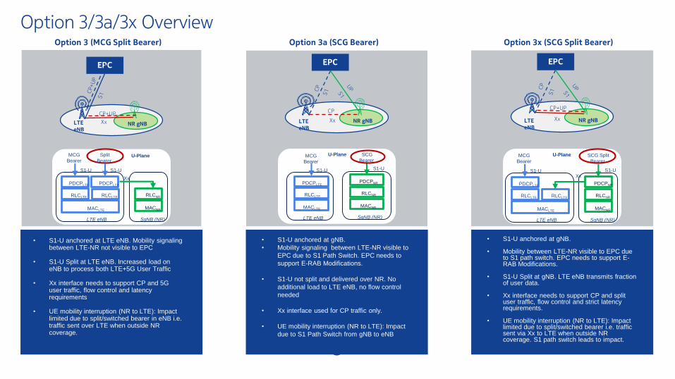
Option 3/3a/3x OverviewOption 3 (MCG Split Bearer)
1
2
3
4
LTE eNB SgNB (NR)
S1-U
Xx
MCG
Bearer
PDCPLTE
RLCLTE
MACLTE
RLCLTE
MACNR
RLCNR
S1-U
Split
Bearer
PDCPLTE
U-Plane
EPC
CP+UP
LTE eNB
NR gNBXx
• S1-U anchored at LTE eNB. Mobility signaling between LTE-NR not visible to EPC
• S1-U Split at LTE eNB. Increased load on eNB to process both LTE+5G User Traffic
• Xx interface needs to support CP and 5G user traffic, flow control and latency requirements
• UE mobility interruption (NR to LTE): Impact limited due to split/switched bearer in eNB i.e. traffic sent over LTE when outside NR coverage.
Option 3a (SCG Bearer)
1
2
3
4
EPC
CP
LTE eNB
NR gNBXx
LTE eNB SgNB (NR)
S1-U
SCG
Bearer MCG
Bearer
S1-U
PDCPLTE
RLCLTE
MACLTEMACNR
RLCNR
PDCPNR
U-Plane
• S1-U anchored at gNB.
• Mobility signaling between LTE-NR visible to
EPC due to S1 Path Switch. EPC needs to
support E-RAB Modifications.
• S1-U not split and delivered over NR. No
additional load to LTE eNB, no flow control
needed
• Xx interface used for CP traffic only.
• UE mobility interruption (NR to LTE): Impact
due to S1 Path Switch from gNB to eNB
Option 3x (SCG Split Bearer)
EPC
CP+UP
LTE eNB
NR gNBXx
LTE eNB SgNB (NR)
S1-UXx
SCG Split
Bearer MCG
Bearer
S1-U
PDCPLTE
RLCLTE
MACLTE
RLCLTE
MACNR
RLCNR
PDCPNR
U-Plane
• S1-U anchored at gNB.
• Mobility between LTE-NR visible to EPC due to S1 path switch. EPC needs to support E-RAB Modifications.
• S1-U Split at gNB. LTE eNB transmits fraction of user data.
• Xx interface needs to support CP and split user traffic, flow control and strict latency requirements.
• UE mobility interruption (NR to LTE): Impact limited due to split/switched bearer i.e. traffic sent via Xx to LTE when outside NR coverage. S1 path switch leads to impact.
Nokia Internal Use
12
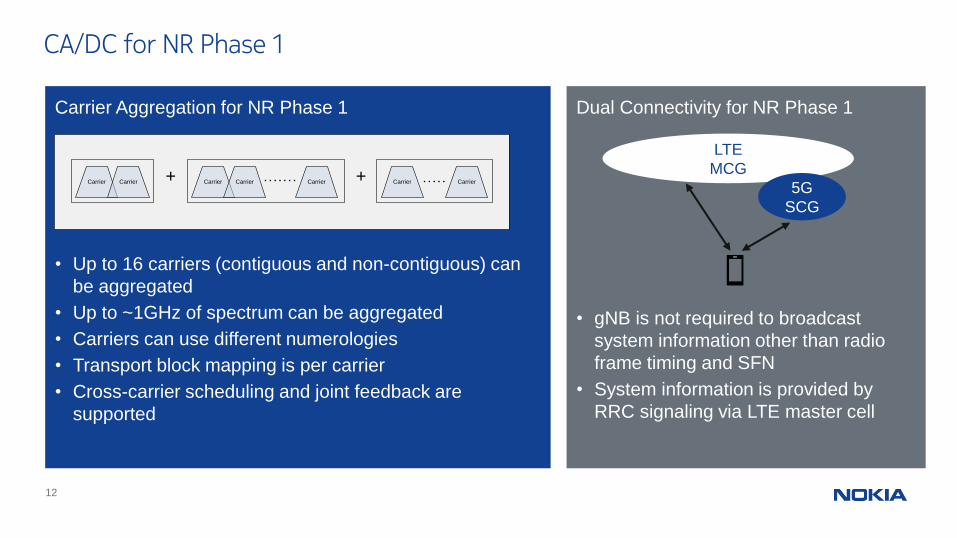
CA/DC for NR Phase 1
Carrier Aggregation for NR Phase 1
• Up to 16 carriers (contiguous and non-contiguous) can
be aggregated
• Up to ~1GHz of spectrum can be aggregated
• Carriers can use different numerologies
• Transport block mapping is per carrier
• Cross-carrier scheduling and joint feedback are
supported
Carrier Carrier Carrier Carrier Carrier Carrier Carrier+ +
Dual Connectivity for NR Phase 1
• gNB is not required to broadcast
system information other than radio
frame timing and SFN
• System information is provided by
RRC signaling via LTE master cell
LTE
MCG
5G
SCG
© 2017 Nokia13
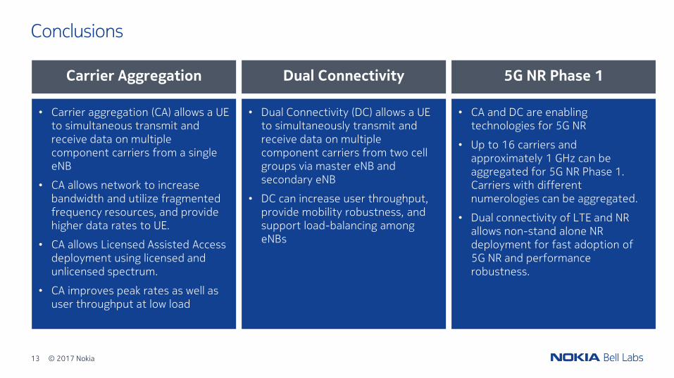
Conclusions
• Carrier aggregation (CA) allows a UE to simultaneous transmit and receive data on multiple component carriers from a single eNB
• CA allows network to increase bandwidth and utilize fragmented frequency resources, and provide higher data rates to UE.
• CA allows Licensed Assisted Access deployment using licensed and unlicensed spectrum.
• CA improves peak rates as well as user throughput at low load
• Dual Connectivity (DC) allows a UE to simultaneously transmit and receive data on multiple component carriers from two cell groups via master eNB and secondary eNB
• DC can increase user throughput, provide mobility robustness, and support load-balancing among eNBs
• CA and DC are enabling technologies for 5G NR
• Up to 16 carriers and approximately 1 GHz can be aggregated for 5G NR Phase 1. Carriers with different numerologies can be aggregated.
• Dual connectivity of LTE and NR allows non-stand alone NR deployment for fast adoption of 5G NR and performance robustness.
Carrier Aggregation Dual Connectivity 5G NR Phase 1