CAB #40291 FOR JOHN DEERE 3120, 3320, 3520, 3720 PARTS LIST – ASSEMBLY INSTRUCTIONS IMPORTANT READ THIS MANUAL CAREFULLY AND KEEP FOR FUTURE REFERENCE CAUTION ! REMOVE THE VINYL PANELS FOR TRANSPORT IN AN OPEN TRUCK OR TRAILER WARNING ! THIS CAB WILL NOT PROTECT OPERATOR FROM INJURIES CAUSED BY ROLLOVER, COLLISION, OR OTHER ACCIDENTS 40291210 1
Transcript
CAB #40291 FOR
JOHN DEERE 3120, 3320, 3520, 3720
PARTS LIST – ASSEMBLY INSTRUCTIONS
IMPORTANT READ THIS MANUAL CAREFULLY AND KEEP FOR FUTURE REFERENCE
CAUTION ! REMOVE THE VINYL PANELS FOR TRANSPORT IN AN OPEN TRUCK OR TRAILER
WARNING ! THIS CAB WILL NOT PROTECT OPERATOR FROM INJURIES CAUSED BY ROLLOVER, COLLISION, OR OTHER
ACCIDENTS
40291210 1
WARNING
This cab is designed to provide foul weather protection only. It does not provide protection from noise, exhaust fumes, chemicals or injury from collision, or other accidents. 1. Do not operate machine in confined areas without proper ventilation 2. Thoroughly check area of operation before using machine 3. The cab adds height to the machine. Low tree limbs and other overhead structures that did not interfere with the operation of the machine before, may now be obstacles
MAINTENANCE INSTRUCTIONS Periodically check all bolts to see that they are tight. If bolts become loose, failure of cab parts may occur. Door latches and hinges should be lubricated with light machine oil for proper operation.
DO NOT CLEAN THE CLEAR PLASTIC WINDOWS WHEN THE PLASTIC IS DRY.
THE CLEAR PLASTIC WILL SCRATCH.
Avoid contact with plastic windows. Keep plastic windows clean by washing them with clear running water and rubbing with your bare hands, only. The use of a rag, sponge or brush will scratch the plastic. Liquid soap may also be used for window cleaning. During freezing weather, an automotive windshield washer solvent may be used. Use liquid soap and water to clean colored vinyl portions. Scrubbing with a brush or rag is also permitted on the colored vinyl portions
STORAGE INSTRUCTIONS Prior to storage clean the windows and colored vinyl parts with a mild automotive detergent, rinse with clean water and allow to thoroughly dry, Store cab in a clean dry place out of direct sunlight. Avoid folding plastic windows.
INSTALLATION
READ THIS MANUAL COMPLETELY BEFORE BEGINNING INSTALLATION. • The right side of the machine is determined from the operators seated position.
• The words "bolt" will refer to a 1/4”x5/8” bolt and "lock nut"’ will refer to a 1/4” locknut unless
specified otherwise. • Do not tighten bolts during assembly unless instructed to do so. • Foldable ROPS must be in the upright position for cab installation and use.
• Park tractor on level ground, lower attachments to ground, remove start key.
2
LIMITED WARRANTY
SNOW REMOVAL EQUIPMENT CABS
COVERED BY WARRANTY
ORIGINAL TRACTOR CAB CO., INC., (the "Company") warrants to the owner that each new product listed below is merchantable and free of defects in workmanship and material. During the warranty period, the dealer from whom the product was bought, or the Company, will provide, free of charge, parts and the shipping costs of parts necessary to correct any defect in workmanship and material.
WARRANTY PERIOD The company products listed below are warranted for the stated period from the date of the original purchase: 1. Cabs for tractors and snow removal equipment 1 Year 2. Company manufactured accessories for above cabs 1 Year 3. Sunshades for lawn and garden tractors 1 Year 4. Repair parts 1 Year
OWNER'S RESPONSIBILITIES The owner of a new Company manufactured product must do the following to qualify for warranty service : 1. Retain the original invoice or other proof of purchase to avoid unnecessary difficulties in determining eligibility for warranty work. 2. Notify the dealer from whom the product was bought, or the company, as soon as possible after discovery of a possible defect, and provide proof of original purchase. To notify the company write to: Original Tractor Cab Co., Inc., P.O. Box 97, Arlington, IN 46104. 3.the owner may , upon notification by the Company, be required to return the defective part, or parts, to the Company for inspection and warranty service.
NOT COVERED BY WARRANTY The following are not covered by this warranty: 1. Transportation charges to and from servicing dealer or the Company; 2. New products, which have been, subject to misuse, negligence or accident, or have been altered or repaired in a manner not authorized by the company; 3. Windshield wipers, lights, or accessories that are warranted separately by their respective manufacturers, except Company agrees to make available to the owner whatever warranty benefits may be made available to the Company by the manufacturers. All implied warranties, except to the extent prohibited by any applicable law, shall have no greater duration than the warranty period for the applicable product, some states do not allow limitation on how long an implied warranty lasts, so the above limitation may not apply to you. The Company’s' liability arising out of warranties representation, instructions, or defects from any abuse, shall be limited exclusively to repair or replacing parts under the condition in the warranty, and in no event will Company be liable for incidental or consequential damages. Some states do not allow the exclusion or limitation of incidental or consequential damages, so the above limitation or exclusion may not apply to you. This warranty gives you specific legal rights, and you may also have rights that vary from state to state. 3
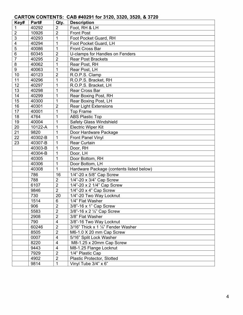
CARTON CONTENTS: CAB #40291 for 3120, 3320, 3520, & 3720 Key# Part# Qty. Description 1 40292 2 Foot, RH & LH 2 10926 2 Front Post 3 40293 1 Foot Pocket Guard, RH 4 40294 1 Foot Pocket Guard, LH 5 40086 1 Front Cross Bar 6 60345 2 U-clamps for Handles on Fenders 7 40295 2 Rear Post Brackets 8 40062 1 Rear Post, RH 9 40063 1 Rear Post, LH 10 40123 2 R.O.P.S. Clamp 11 40296 1 R.O.P.S. Bracket, RH 12 40297 1 R.O.P.S. Bracket, LH 13 40298 1 Rear Cross Bar 14 40299 1 Rear Boxing Post, RH 15 40300 1 Rear Boxing Post, LH 16 40301 2 Rear Light Extensions 17 40001 1 Top Frame 18 4764 1 ABS Plastic Top 19 40004 1 Safety Glass Windshield 20 10122-A 1 Electric Wiper Kit 21 9820 1 Door Hardware Package 22 40302-B 1 Front Panel Vinyl 23 40307-B 1 Rear Curtain 40303-B 1 Door, RH 40304-B 1 Door, LH 40305 1 Door Bottom, RH 40306 1 Door Bottom, LH 40308 1 Hardware Package (contents listed below) 786 16 1/4”-20 x 5/8” Cap Screw 788 2 1/4”-20 x 3/4” Cap Screw 6107 2 1/4”-20 x 2 1/4” Cap Screw 9846 2 1/4”-20 x 4” Cap Screw 730 20 1/4”-20 Two Way Locknut 1514 6 1/4” Flat Washer 906 2 3/8”-16 x 1” Cap Screw 5583 2 3/8”-16 x 2 ¼” Cap Screw 2908 2 3/8” Flat Washer 790 4 3/8”-16 Two Way Locknut 60246 2 3/16” Thick x 1 ¼” Fender Washer 8505 2 M6-1.0 X 20 mm Cap Screw 0007 4 5/16” Split Lock Washer 8220 4 M8-1.25 x 20mm Cap Screw 9443 4 M8-1.25 Flange Locknut 7929 2 1/4” Plastic Cap 4902 2 Plastic Protector, Slotted 9814 1 Vinyl Tube 3/4” x 6”
4
Figure 1
Step 1; See Figure 1: Use the parts list and Figure 1 to identify the steel parts.
1
2
3
4
5
6
6
7
7
10
11
12
15
14
13
5
Step 2; See Figure 2: Install Rear Light Extensions (16).
Figure 2
A. Remove the light by loosening the bolts at Reference A. Place the Rear Light Extension over the bolts. Add M-8 Flange Locknuts and tighten. B. Place the light onto the extension. Insert two M-8 x 20mm bolts with lock washers into the light and tighten.
Step 3; See Figure 3: Install Feet (1) and right and left Foot Pocket
Guards (3&4).
Figure 3
A. Pull back the rubber mat and remove the bolt at Reference B. Place a fender washer over the hole. Place a Foot on the step plate as shown. Insert a 3/8” x 2 1/4” bolt down through the hole. Add a 3/8” locknut. Do not tighten at this time. B. Open the hood and remove the screw at Reference C using a T-25 Torx bit. Place a Foot Pocket Guard, with the slot pointing downward, on the dash as shown. Insert a M6 x 20mm bolt with 1/4” flat washer into the holes. Tighten the screw enough to keep the Foot Pocket Guard in line with the top of the Foot as shown. Do not over tighten the bolt.
16
A
B
C
6
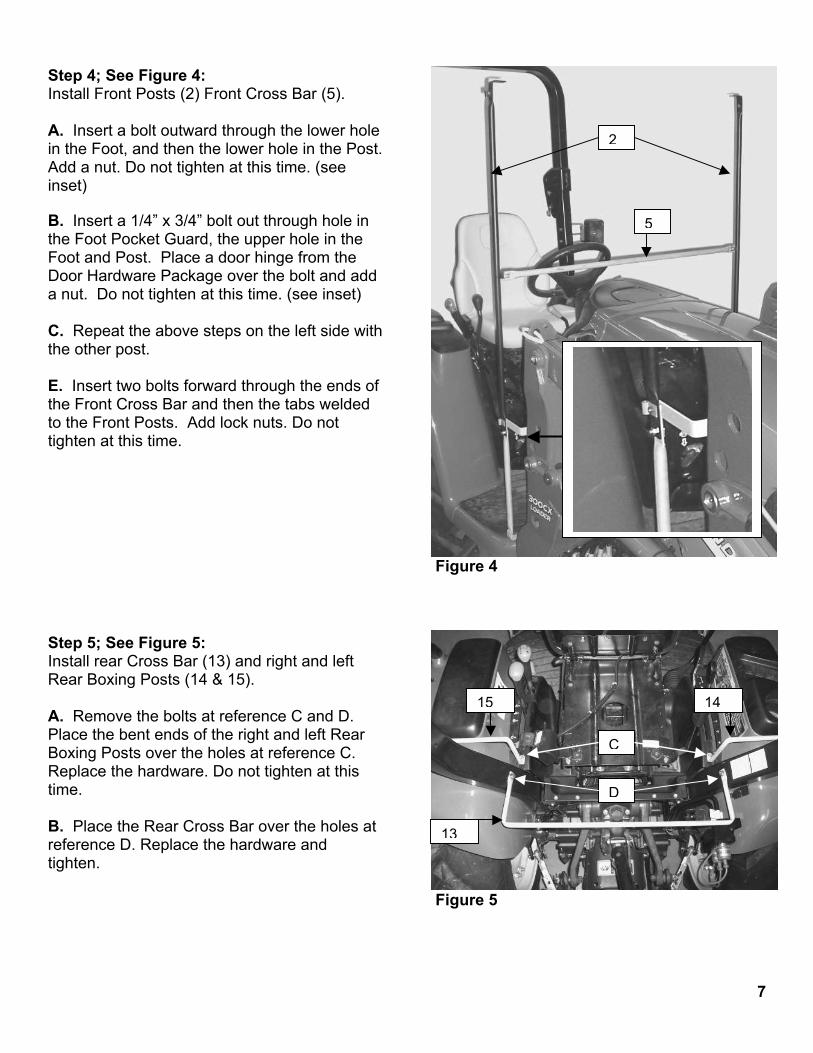
Step 4; See Figure 4:
Figure 4
Install Front Posts (2) Front Cross Bar (5). A. Insert a bolt outward through the lower hole in the Foot, and then the lower hole in the Post. Add a nut. Do not tighten at this time. (see inset) B. Insert a 1/4” x 3/4” bolt out through hole in the Foot Pocket Guard, the upper hole in the Foot and Post. Place a door hinge from the Door Hardware Package over the bolt and add a nut. Do not tighten at this time. (see inset) C. Repeat the above steps on the left side with the other post. E. Insert two bolts forward through the ends of the Front Cross Bar and then the tabs welded to the Front Posts. Add lock nuts. Do not tighten at this time.
Figure 5
Step 5; See Figure 5: Install rear Cross Bar (13) and right and left Rear Boxing Posts (14 & 15). A. Remove the bolts at reference C and D. Place the bent ends of the right and left Rear Boxing Posts over the holes at reference C. Replace the hardware. Do not tighten at this time. B. Place the Rear Cross Bar over the holes at reference D. Replace the hardware and tighten.
C
D
2
5
13
14
15
7
Step 6; See Figure 6:
Install Top Frame (17) ROPS Clamps (10) & right and left ROPS bracket (11 & 12). A. Place the Top Frame onto the bent ends of the Front Posts and the right and left Boxing posts. Insert four bolts upwards and add nuts. Do not tighten at this time. B. Place a “U” Clamp open end to the outside over the right ROPS bar. Insert a 1/4” x 4” bolt through the right ROPS Bracket and then the clamp. Add a nut. Do not tighten at this time. C. Insert a 3/8” x 1” bolt up through the hole in the right ROPS Bracket and then the slotted tab at the rear of the Top Frame. Place a 3/8” Flat Washer over the bolt and add a 3/8” Locknut. Do not tighten at this time. Step 7; See Figure 7: Install Rear Post Brackets (7), U Clamps (6) and Rear Posts (8 & 9). A. Cut the vinyl tube into 2 - 3” pieces. Split both pieces lengthwise and cover the inside of the clamps with the pieces. This will help protect your plastic handles. B. Place a “U” Clamp open end down over the right handle. Insert a 1/4” x 2 1/4” bolt inwards through the holes. Place a Rear Post Bracket over the bolt and add a nut. Do not tighten at this time. C. Insert two bolts upwards through the bent ends of the Rear Posts and “L” tabs welded to the Top Frame. Add locknuts. Do not tighten at this time. B. Insert a bolt out through the bottom of the Rear Post then the top of the Rear Post Bracket and add a locknut. Do not tighten at this time.
17
11
10
Figure 6
Figure 7
8
6Note: When Rear posts are properly installed, latch plates will be to the front with the notch to the outside of the enclosure.
7
8
Step 8; See Figure 8:
Install the Doors for frame / door alignment. A. Follow the instructions in the Door Hardware Package to install the Door Bottoms and the Door Latches.
B. Install, close and latch both Doors. C. Tighten all bolts from previous steps at this time. D. Remove the doors by lifting the door up and out of the bottom hinge then lowering out of the top hinge. E. Place a notched plastic protector over the bent ends of each rear post. (see inset) F. Place the small 1/4” plastic protectors over the threaded ends of the bolts under the plastic handles on the fenders. Figure 8 Step 9; See Figure 9: Install Rear Curtain (23). A. Close the hook and loop flaps around the top frame at the back and sides. B. Fit the vinyl around the Rear Boxing Posts and Rear Cross Bar. C. Close the hook and loop flaps around the rear posts.
Figure 9
23
9
Step 10; See Figure 10 & 10A:
Figure 10A
Install Front Panel Vinyl (22) A. Open the hood and place the Front Panel Vinyl over the dash. Lay the rod sewn into the top of the Front Panel Vinyl over the Front Panel Frame. Close the hook and loop flaps around the Front Posts. B. Fit the vinyl around the Foot Pocket Guards and secure the hook and loop tabs together. C. Hook the springs under the step plate on the right and left sides as shown.
22
22
Figure 10
Right Spring
Left Spring 10
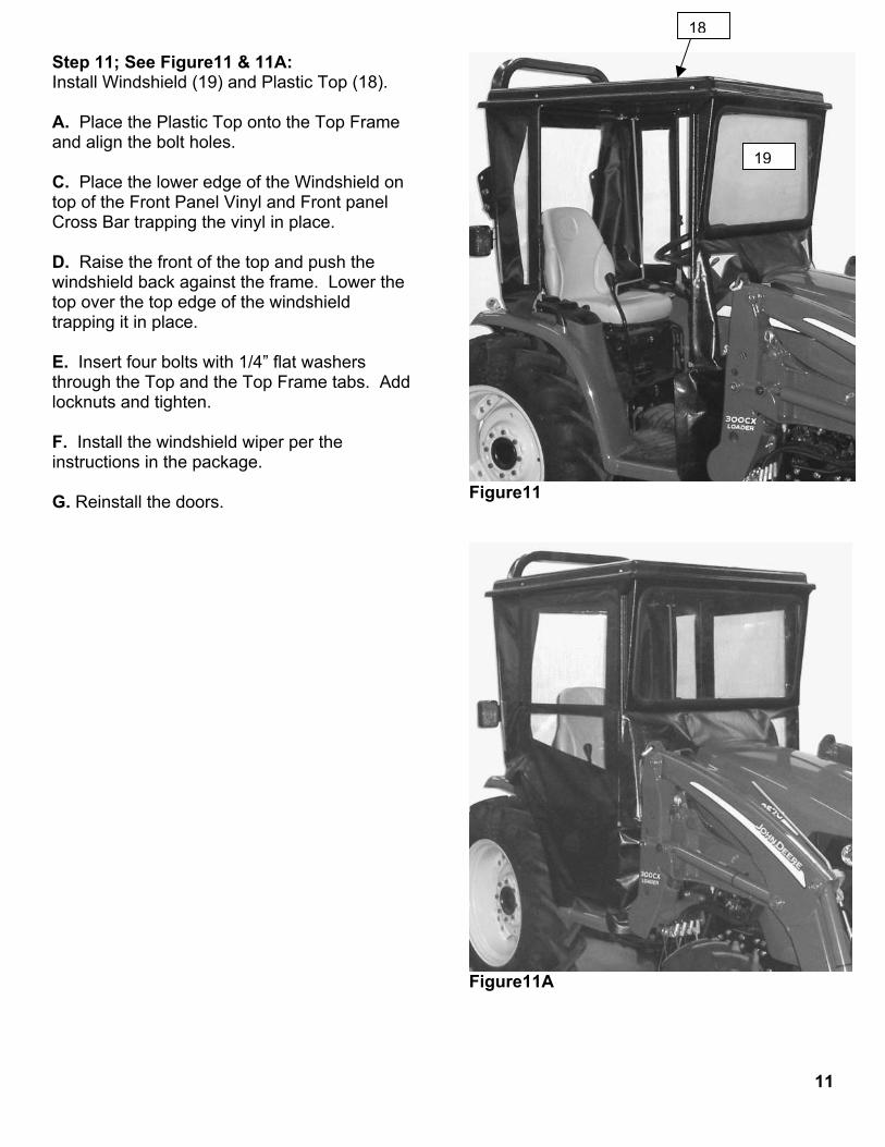
Step 11; See Figure11 & 11A:
Figure11
Install Windshield (19) and Plastic Top (18). A. Place the Plastic Top onto the Top Frame and align the bolt holes. C. Place the lower edge of the Windshield on top of the Front Panel Vinyl and Front panel Cross Bar trapping the vinyl in place. D. Raise the front of the top and push the windshield back against the frame. Lower the top over the top edge of the windshield trapping it in place. E. Insert four bolts with 1/4” flat washers through the Top and the Top Frame tabs. Add locknuts and tighten. F. Install the windshield wiper per the instructions in the package. G. Reinstall the doors.
Figure11A
18
19
11
For Replacement Parts and Accessories Contact:
Original Tractor Cab Co., Inc. P.O. Box 97 6849 W. Front St.
Arlington, IN 46104 Phone 765-663-2214 Fax 765-663-2101