Page 1
c International Journal of Research (IJR)
e-ISSN: 2348-6848, p- ISSN: 2348-795X Volume 3, Issue 01, January 2016
Available at http://internationaljournalofresearch.org
Available online:http://internationaljournalofresearch.org/ P a g e | 232
Cascaded Two-Level Inverter using Fuzzy logic Based multilevel STATCOM for High –Power Applications
S.Satya Sri 1 & K.Kranthi Pratap Singh 2
1M.Tech Scholar, Dept of EEE, A.S.R College of Engineering and Technology, JNTUK, A.P
2Assistant Professor, Dept of EEE, A.S.R College of Engineering and Technology, JNTUK, A.P
Abstract:— Multilevel inverters have received more attentions
their considerable advantages such as high power quality, lower harmonic components, better electro-
magnetic consistence, lower dv/dt and lower
switching losses. Lot of research was going on multi
level inverter topologies and many researchers are proposed so many multi level inverter topologies. In
this paper, a simple static var compensating scheme
using a cascaded two-level inverter-based multilevel inverter is proposed. The topology consists of two
standard two-level inverters connected in cascade
through open-end windings of a three-phase transformer. The dc-link voltages of the inverters are
regulated at different levels to obtain four-level
operation. The simulation study is carried out in
MATLAB/SIMULINK to predict the performance of the proposed scheme under balanced and unbalanced
supply-voltage conditions.
Keywords: DC-link voltage balance; multilevel
inverter; power quality (PQ); static compensator
(STATCOM)
I. INTRODUCTION
The application of (FACTS) controllers, such
flexible ac transmission systems as static
compensator (STATCOM) and static synchronous
series compensator (SSSC), is increasing in power
systems.This is due to their ability to stabilize the
transmission systems and to improve power quality
(PQ) in distribution systems. STATCOM is popularly
accepted as a reliable reactive power controller
replacing conventional var compensators, such as the
thyristor-switched capacitor (TSC) and thyristor-
controlled reactor (TCR). This device provides
reactive power compensation, active power
oscillation damping, flicker attenuation, voltage
regulation, etc...
Generally, in high-power applications, var
compensation is achieved using multilevel inverters
[2]. These inverters consist of a large number of dc
sources which are usually realized by capacitors.
Hence, the converters draw a small amount of active
power to maintain dc voltage of capacitors and to
compensate the losses in the converter. However, due
to mismatch in conduction and switching losses of the
switching devices, the capacitors voltages are
unbalanced. Balancing these voltages is a major
research challenge in multilevel inverters. Various
control schemes using different topologies are
reported in [3]–[7]. Among the three conventional
multilevel inverter topologies cascade H-bridge is the
most popular for static var compensation [5], [6].
However, the aforementioned topology requires a
large number of dc capacitors. The control of
individual dc-link voltage of the capacitors is
difficult.
Each bidirectional power switch includes two
IGBTs, two power diodes, and one driver circuit if
the common emitter configuration is used. Therefore,
in these topologies, the installation space and total
cost of the inverter increase. As a result, several
asymmetric cascaded multilevel inverters have been
presented in which the unidirectional switches from
the voltage point of view and the bidirectional
switches from the current point of view are used in
them. Each unidirectional switch consists of an IGBT
with an anti parallel diode. Two of these topologies
have been presented in [20]. Two other algorithms for
the H-bridge cascaded multilevel inverter have been
also presented in [9] and [10]. Because of the
asymmetric topology and used unidirectional
switches, it seems that the lower number of power
electronic devices is the main advantage of these
inverters. However, the main disadvantage of the
asymmetric topologies is the lost of modularity,
Page 2
c International Journal of Research (IJR)
e-ISSN: 2348-6848, p- ISSN: 2348-795X Volume 3, Issue 01, January 2016
Available at http://internationaljournalofresearch.org
Available online:http://internationaljournalofresearch.org/ P a g e | 233
which means the use of a high variety of
semiconductor devices and dc voltage sources.
Various var compensation schemes based on this
topology are reported in [8]–[10]. In [9], a three-level
inverter and two level inverter are connected on either
side of the transformer
low-voltage winding. The dc-link voltages are
maintained by separate converters. In [10], three-level
operation is obtained by using standard two-level
inverters. The dc-link voltage balance between the
inverters is affected by the reactive power supplied to
the grid.
II. PROPOSED TOPOLOGY- CASCADED TWO-
LEVEL INVERTER-BASED
MULTILEVEL STATCOM
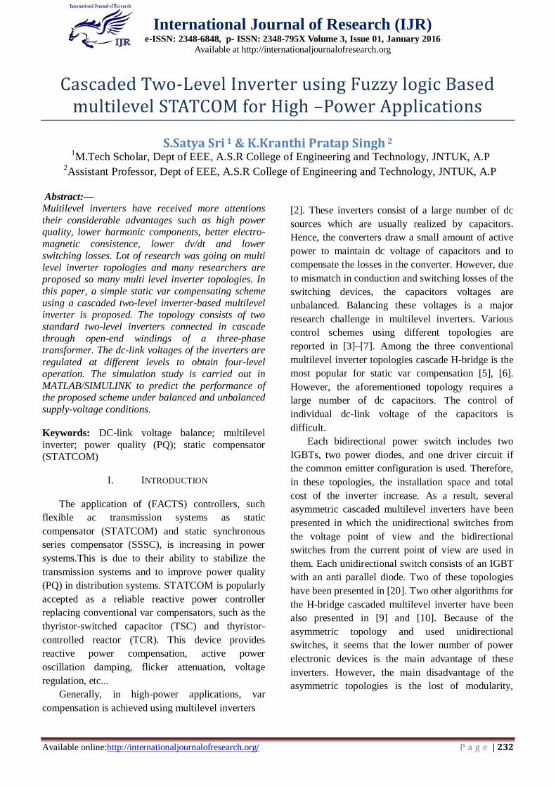
Fig. 1 shows the power system model
considered in this paper [10]. Fig. 2 shows the
circuit topology of the cascaded two-level inverter-
based multilevel STATCOM using standard two-
level inverters. The inverters are connected on the
low-voltage (LV) side of the transformer and the
high-voltage (HV) side is connected to the grid.
The dc-link voltages of the inverters are maintained
constant and modulation indices are controlled to
achieve the required objective. The proposed
control scheme is derived from the ac side of the
equivalent circuit which is shown in Fig. 3. In the
figure, and are the source voltages referred to LV
side of the transformer, and are the resistances
which represent the losses in the transformer and
two inverters, and are leakage inductances of
transformer windings, and and are the output
voltages of inverters 1 and 2, respectively. are the
leakage resistances of dc-link capacitors and ,
respectively. Assuming and applying KVL on the
ac side, the dynamic model can be derived using
[10] as
Above equation represents the mathematical model of
the cascaded two-level inverter-based multilevel
STATCOM in the stationary reference frame. This
model is transformed to the synchronously rotating
reference frame [10]. The dq– axes reference voltage
components of the converter and are controlled as
Fig. 1. Power system and the STATCOM model
Fig. 2. Cascaded two-level inverter-based multilevel
STATCOM
Fig. 3. Equivalent circuit of the cascaded two level
inverter-based multilevel STATCOM
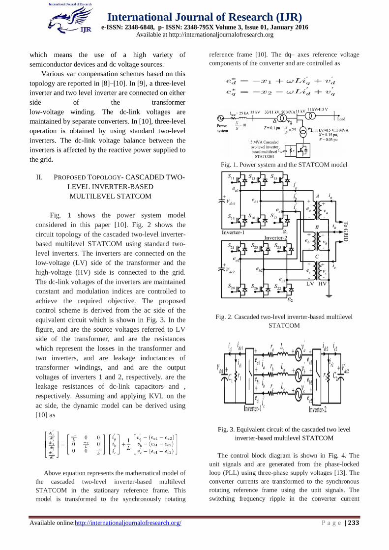
The control block diagram is shown in Fig. 4. The
unit signals and are generated from the phase-locked
loop (PLL) using three-phase supply voltages [13]. The
converter currents are transformed to the synchronous
rotating reference frame using the unit signals. The
switching frequency ripple in the converter current
Page 3
c International Journal of Research (IJR)
e-ISSN: 2348-6848, p- ISSN: 2348-795X Volume 3, Issue 01, January 2016
Available at http://internationaljournalofresearch.org
Available online:http://internationaljournalofresearch.org/ P a g e | 234
components is eliminated using a low-pass filter (LPF).
From and loops, the controller generates – axes reference
voltages, and for the cascaded inverter. With these
reference voltages, the inverter supplies the desired
reactive current
and draws required active current to regulate total dc-
link voltage. However, this will not ensure that
individual dc-link voltages are controlled at their
respective reference values. Hence, additional control is
required to regulate individual dc-link voltages of the
inverters.
Fig. 4. Control block diagram of proposed system
Network voltages are unbalanced due to
asymmetric faults or unbalanced loads [13]. As a result,
negative-sequence voltage appears in the supply voltage.
This causes a double supply frequency component in the
dc-link voltage of the inverter. This double frequency
component injects the third harmonic component in the
ac side [13]. Moreover, due to negative-sequence
voltage, large negative-sequence current flows through
the inverter which may cause the STATCOM to trip.
Therefore, during unbalance, the inverter voltages are
controlled in such a way that either negative-sequence
current flowing into the inverter is eliminated or reduces
the unbalance in the grid voltage. In the latter case,
STATCOM needs to supply large currents since the
interfacing impedance is small. This may lead to tripping
of the converter.
All the mathematical calculated simulation
parameters are given in the Appendix section.
III. MATLAB BASED SIMULATION & IT’S
RESULTS
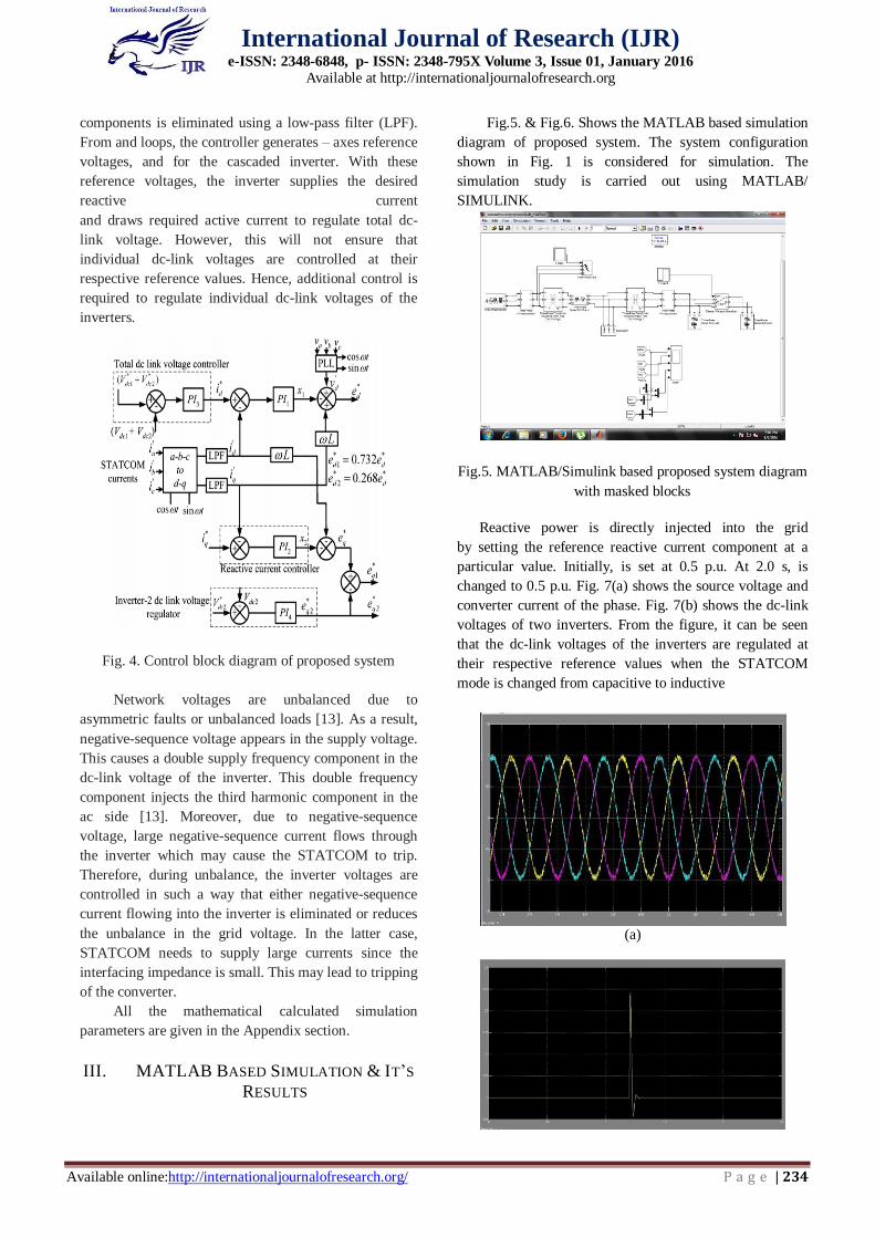
Fig.5. & Fig.6. Shows the MATLAB based simulation
diagram of proposed system. The system configuration
shown in Fig. 1 is considered for simulation. The
simulation study is carried out using MATLAB/
SIMULINK.
Fig.5. MATLAB/Simulink based proposed system diagram
with masked blocks
Reactive power is directly injected into the grid
by setting the reference reactive current component at a
particular value. Initially, is set at 0.5 p.u. At 2.0 s, is
changed to 0.5 p.u. Fig. 7(a) shows the source voltage and
converter current of the phase. Fig. 7(b) shows the dc-link
voltages of two inverters. From the figure, it can be seen
that the dc-link voltages of the inverters are regulated at
their respective reference values when the STATCOM
mode is changed from capacitive to inductive
(a)
Page 4
c International Journal of Research (IJR)
e-ISSN: 2348-6848, p- ISSN: 2348-795X Volume 3, Issue 01, January 2016
Available at http://internationaljournalofresearch.org
Available online:http://internationaljournalofresearch.org/ P a g e | 235
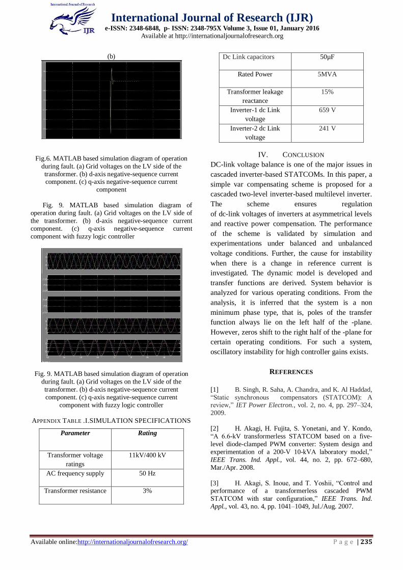
(b)
Fig.6. MATLAB based simulation diagram of operation
during fault. (a) Grid voltages on the LV side of the
transformer. (b) d-axis negative-sequence current component. (c) q-axis negative-sequence current
component
Fig. 9. MATLAB based simulation diagram of
operation during fault. (a) Grid voltages on the LV side of
the transformer. (b) d-axis negative-sequence current
component. (c) q-axis negative-sequence current
component with fuzzy logic controller
Fig. 9. MATLAB based simulation diagram of operation
during fault. (a) Grid voltages on the LV side of the
transformer. (b) d-axis negative-sequence current
component. (c) q-axis negative-sequence current
component with fuzzy logic controller
APPENDIX TABLE .I.SIMULATION SPECIFICATIONS
Parameter Rating
Transformer voltage
ratings
11kV/400 kV
AC frequency supply 50 Hz
Transformer resistance 3%
Dc Link capacitors 50µF
Rated Power 5MVA
Transformer leakage
reactance
15%
Inverter-1 dc Link
voltage
659 V
Inverter-2 dc Link
voltage
241 V
IV. CONCLUSION
DC-link voltage balance is one of the major issues in
cascaded inverter-based STATCOMs. In this paper, a
simple var compensating scheme is proposed for a
cascaded two-level inverter-based multilevel inverter.
The scheme ensures regulation
of dc-link voltages of inverters at asymmetrical levels
and reactive power compensation. The performance
of the scheme is validated by simulation and
experimentations under balanced and unbalanced
voltage conditions. Further, the cause for instability
when there is a change in reference current is
investigated. The dynamic model is developed and
transfer functions are derived. System behavior is
analyzed for various operating conditions. From the
analysis, it is inferred that the system is a non
minimum phase type, that is, poles of the transfer
function always lie on the left half of the -plane.
However, zeros shift to the right half of the -plane for
certain operating conditions. For such a system,
oscillatory instability for high controller gains exists.
REFERENCES
[1] B. Singh, R. Saha, A. Chandra, and K. Al Haddad,
“Static synchronous compensators (STATCOM): A review,” IET Power Electron., vol. 2, no. 4, pp. 297–324,
2009.
[2] H. Akagi, H. Fujita, S. Yonetani, and Y. Kondo,
“A 6.6-kV transformerless STATCOM based on a five-
level diode-clamped PWM converter: System design and
experimentation of a 200-V 10-kVA laboratory model,”
IEEE Trans. Ind. Appl., vol. 44, no. 2, pp. 672–680,
Mar./Apr. 2008.
[3] H. Akagi, S. Inoue, and T. Yoshii, “Control and performance of a transformerless cascaded PWM
STATCOM with star configuration,” IEEE Trans. Ind.
Appl., vol. 43, no. 4, pp. 1041–1049, Jul./Aug. 2007.
Page 5
c International Journal of Research (IJR)
e-ISSN: 2348-6848, p- ISSN: 2348-795X Volume 3, Issue 01, January 2016
Available at http://internationaljournalofresearch.org
Available online:http://internationaljournalofresearch.org/ P a g e | 236
[4] H. P. Mohammadi and M. T. Bina, “A
transformerless medium-voltage STATCOM topology
based on extended modular multilevel converters,” IEEE
Trans. Power Electron., vol. 26, no. 5, pp. 1534–1545,
May 2011.
[5] N. N. V. Surendra Babu, D. Apparao, and B. G. Fernandes, “Asymmetrical dc link voltage balance of a
cascaded two level inverter based
STATCOM,” in Proc., IEEE TENCON, 2010, pp. 483–
488.
[6] A. Leon, J. M. Mauricio, J. A. Solsona, and A.
Gomez-Exposito, “Software sensor-based STATCOM
control under unbalanced conditions,” IEEE Trans. Power
Del., vol. 24, no. 3, pp. 1623–1632, Jul. 2009.
[7] Y. Suh, Y. Go, and D. Rho, “A comparative study on control algorithm for active front-end rectifier of large
motor drives under unbalanced input,” IEEE Trans. Ind.
Appl., vol. 47, no. 3, pp. 825–835, May/Jun. 2011.
[8] S. Laali, K. Abbaszades, and H. Lesani, “New
hybrid control methods based on multi-carrier PWM
techniques and charge balance control methods for
cascaded multilevel converters,” in Proc. CCECE, 2011
pp. 243–246.
[9] J. Napoles, A. J. Watson, and J. J. Padilla, “Selective harmonic mitigation technique for cascaded H-
bridge converter with nonequal dc link voltages,” IEEE
Trans. Ind. Electron., vol. 60, no. 5, pp. 1963–1971, May
2013.
[10] N. Farokhnia, S. H. Fathi, N. Yousefpoor, and M.
K. Bakhshizadeh, “Minimisation of total harmonic
distortion in a cascaded multilevel inverter by regulating of
voltages dc sources,” IET Power Electron., vol. 5, no. 1,
pp. 106–114, Jan. 2012.
[11] Welflen Ricardo Nogueira Santos , Edison Roberto Cabral da Silva and Cursino Brandao Jacobina ,
“The Transformerless Single-Phase Universal Active
Power Filter for Harmonic and Reactive Power
Compensation”, IEEE Transactions on Power Vol.29 ,
No.7 , pp. 3563- 3572 July 2014
[12] Y. Tang, P. C. Loh, P. Wang, F. H. Choo, F. Gao,
and F. Blaabjerg, “Generalized design of high performance
shunt active power filter with output lcl filter,” IEEE
Trans. Ind. Electron., vol. 59, no. 3, pp. 1443–1452, Mar.
2012
[13] E. Babaei, “Optimal topologies for cascaded sub-
multilevel converters,” J. Power Electron., vol. 10, no. 3,
pp. 251–261, May 2010.
[14] E. Babaei, S. Alilu, and S. Laali, “A new general
topology for cascaded multilevel inverters with reduced
number of components based on developed H-bridge,”
IEEE Trans. Ind. Electron., vol. 61, no. 8, pp. 3932–3939,
Aug. 2014.
[15] J. Ebrahimi, E. Babaei, and G. B. Gharehpetian,
“A new topology of cascaded multilevel converters with
reduced number of components for high-voltage
applications,” IEEE Trans. Power Electron., vol. 26, no. 11,
pp. 3119–3130, Nov. 2011.
[16] A. Luo, S. Peng, C. Wu, J. Wu, and Z. Shuai,
“Power electronic hybrid system for load balancing
compensation and frequency-selective harmonic
suppression,” IEEE Trans. Ind. Electron., vol. 59, no. 2,
pp. 723–732, Feb. 2012.
[17] Q.-N. Trinh and H.-H. Lee, “An advanced current
control strategy for three-phase shunt active power filters,” IEEE Trans. Ind. Electron., vol. 60, no. 12, pp. 5400–5410,
Dec. 2013.
[18] S. Laali, K. Abbaszades, and H. Lesani, “A new
algorithm to determine the magnitudes of dc voltage
sources in asymmetrical cascaded multilevel converters
capable of using charge balance control methods,” in Proc.
ICEMS, Incheon, Korea, 2010, pp. 56–61.
[19] M. F. Kangarlu and E. Babaei, “A generalized
cascaded multilevel inverter using series connection of sub-multilevel inverters,” IEEE Trans. Power Electron.,
vol. 28, no. 2, pp. 625–636, Feb. 2013.
[20] J. Pereda and J. Dixon, “Cascaded multilevel
converters: Optimal asymmetries and floating capacitor
control,” IEEE Trans. Ind. Electron., vol. 60, no. 11, pp.
4784–4793, Nov. 2013.
[21] E. Babaei, M. Farhadi Kangarlu, and F. Najaty
Mazgar, “Symmetric and asymmetric multilevel inverter
topologies with reduced switching devices,” Elect. Power
Syst. Res., vol. 86, pp. 122–130, May 2012.