Case – 13 Food Storage & Processing Center Copy Right By: Thomas T.S. Wan (温到祥) Feb. 2, 2002 All Rights Reserved Case Background: The refrigeration system is for a food processing and storage facility. The general specifications and requirements are outlined as the following: 1.0 A central engine room is used. The refrigeration system is to be with a remote mounted evaporative condenser. The outside air design temperatures are 92°FDB and 81°FWB in the summer; the minimum temperature is 45°F in the wintertime. 2.0 Refrigerant shall be Ammonia (R-717). The system shall be designed for multiple evaporative temperature levels. Liquid recirculation is to be used for all the users and the evaporators. One liquid recirculation receiver package shall be arranged independently for each evaporative temperature level. 3.0 Screw compressor shall be used. One compressor shall be allocated for each suction temperature level. The overall compression ratio of each compressor shall not be over 7.5; the system shall be compound system, compressors are without economizing. Flash type vertical Intermediate intercooler, shall be used. Oil coolers shall be water cooled, but the water shall be closed circuit and cooled by evaporative fluid cooler. The nameplate HP for the driving motor for each compressor shall be no more than 550 HP to reduce the inrush current during start-up of the compressor. The condensing temperature of the system shall be allowed to decrease when outdoor ambient temperature decreases for the benefit of operating cost reduction. 4.0 One stand-by compressor unit is to be used and connected in such way to provide service in case of any one of the compressors of the system is in service repair. 5.0 The refrigeration loads and the minimum air coolers to be used for the user as the following: Blast Freezing Room. The room temperature is -40°F. Total Refrigeration load is 87 TR. Minimum 6 product coolers shall be used. Cold Storage Room. Room design temperature -3°F. Total refrigeration load is 65 TR, minimum 4 coolers shall be used.
Transcript
Case – 13 Food Storage & Processing Center
Copy Right By: Thomas T.S. Wan
(温到祥) Feb. 2, 2002
All Rights Reserved Case Background: The refrigeration system is for a food processing and storage facility. The general specifications and requirements are outlined as the following: 1.0 A central engine room is used. The refrigeration system is to be with a remote
mounted evaporative condenser. The outside air design temperatures are 92°FDB and 81°FWB in the summer; the minimum temperature is 45°F in the wintertime.
2.0 Refrigerant shall be Ammonia (R-717). The system shall be designed for multiple
evaporative temperature levels. Liquid recirculation is to be used for all the users and the evaporators. One liquid recirculation receiver package shall be arranged independently for each evaporative temperature level.
3.0 Screw compressor shall be used. One compressor shall be allocated for each suction
temperature level. The overall compression ratio of each compressor shall not be over 7.5; the system shall be compound system, compressors are without economizing. Flash type vertical Intermediate intercooler, shall be used. Oil coolers shall be water cooled, but the water shall be closed circuit and cooled by evaporative fluid cooler. The nameplate HP for the driving motor for each compressor shall be no more than 550 HP to reduce the inrush current during start-up of the compressor. The condensing temperature of the system shall be allowed to decrease when outdoor ambient temperature decreases for the benefit of operating cost reduction.
4.0 One stand-by compressor unit is to be used and connected in such way to provide
service in case of any one of the compressors of the system is in service repair. 5.0 The refrigeration loads and the minimum air coolers to be used for the user as the
following: Blast Freezing Room. The room temperature is -40°F. Total Refrigeration load is 87
TR. Minimum 6 product coolers shall be used. Cold Storage Room. Room design temperature -3°F. Total refrigeration load is 65
TR, minimum 4 coolers shall be used.
Chilled Room. Room temperature 28°F. Total refrigeration load is 28 TR. Minimum 4 coolers shall be used.
Loading Room. Room temperature 32°F. Total refrigeration load is 54 TR.
Minimum 4 coolers shall be used. Ante Room. Room temperature 35°F. Total refrigeration load is 9.2 TR. Minimum 2
coolers shall be used. Boxing Room. Room temperature 46°F. Total refrigeration load is 15 TR. Minimum
2 coolers shall be used. Deboning Room. Room temperature 43°F. Total refrigeration load is 17.9 TR.
Minimum 4 units shall be used. A brine chiller is to cool 464 GPM 45% by weight of Propylene Glycol brine from
49°F to 38°F leaving. Flake Ice Making. The ice maker is provided by the customer, but, the central
refrigeration system is to provide the Ammonia liquid for the refrigeration. The design refrigeration capacity for the ice making is 61 tons of refrigeration. The owner would like to be advised as what ET is to be used for the ice maker.
6.0 The power supply: Main motors 4160-3-60 Small motors 460-3-60 Control & heater 120-1-60 7.0 All the high side equipment and the liquid recirculation packages are located in the
engine room, except the evaporative condensers and the fluid coolers. The engine room size is 80' x 40' x 20'H. The farthest cold room from the engine room is the blast freezing room, the distance between the Blast Freezing Room to the engine room is about 200 feet. Minimum of 5 elbows for each suction piping run should be allowed.
Related Technical Data and Information for the Case: Figure 13-1 Specific Gravity – Propylene Glycol Figure 13-2 Specific Heat – Propylen Glycol Figure 13-3 Typical Ammonia Product Cooler Figure 13-4 Typical Product Coolers Data from Maker 3/4”OD Steel Coils Figure 13-5 Typical Unit Coolers Data from Maker Figure 13-6 Typical Induced Draft Evaporative Condenser from a Maker Figure 13-7 Typical Performance Data for Evaporative Condenser for R-717 Figure 13-8 Typical Performance Curves for Evaporative Fluid Cooler Figure 13-9 Typical Capacities of Evaporative Fluid Cooler from a Maker Figure 13-10 Maximum Gas/Liquid Gravity Separation Velocity
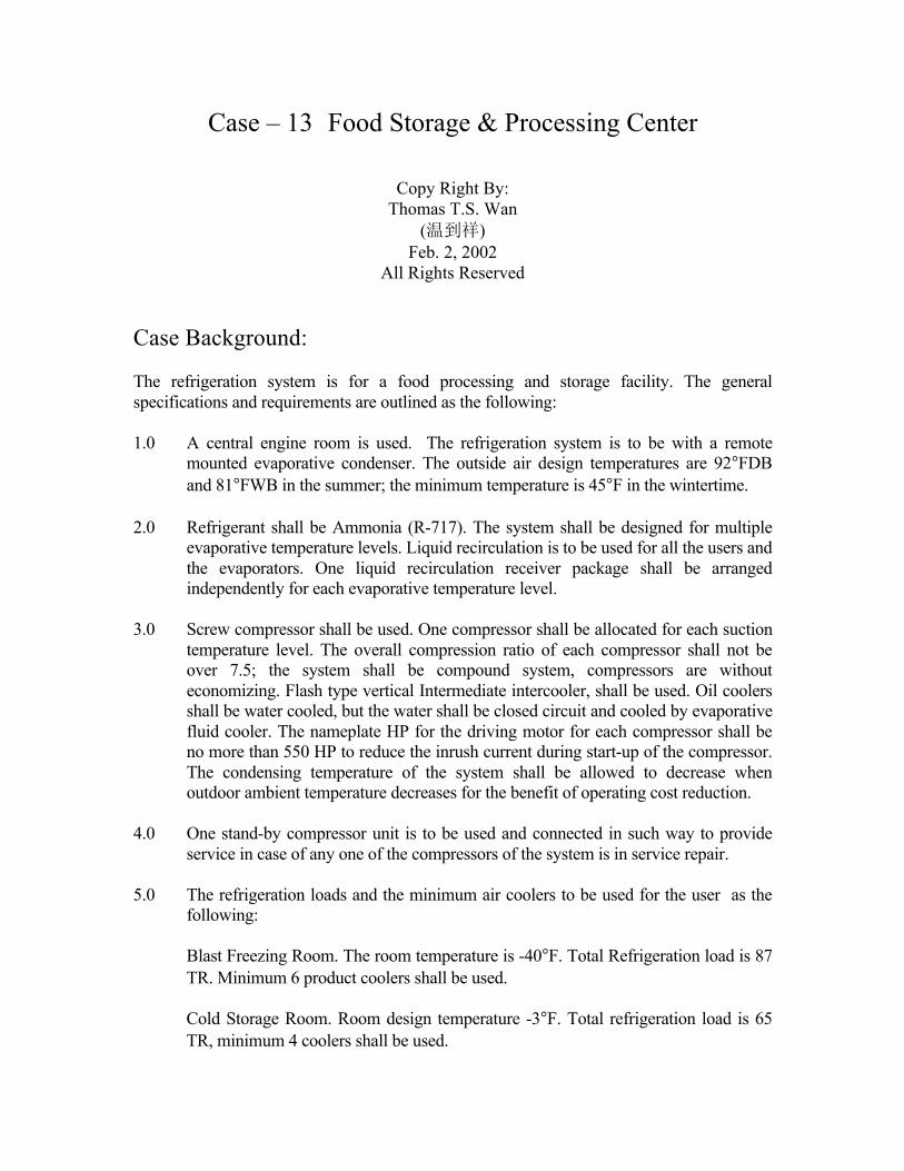
Figure 13-1 Specific Gravity – Propylene Glycol
Figure 13-2 Specific Heat – Propylen Glycol
Figure 13-3 Typical Ammonia Product Cooler
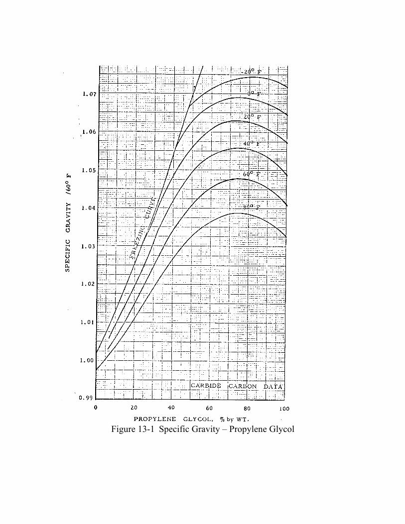
Figure 13-4 Typical Product Coolers Data from Maker 3/4”OD Steel Coils
For Air Deforst, Water Defrost, Hot Gas Defrost
Figure 13-5 Typical Unit Coolers Data from Maker
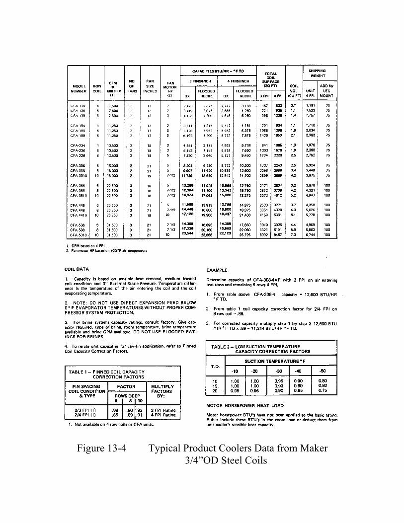
Figure 13-6 Typical Induced Draft Evaporative Condenser from a Maker
Figure 13-7 Typical Performance Data for Evaporative Condenser for R-717
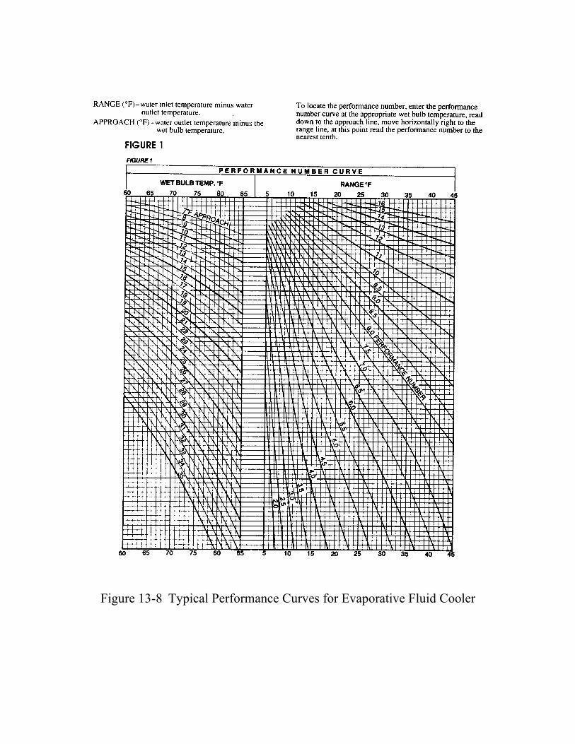
Figure 13-8 Typical Performance Curves for Evaporative Fluid Cooler
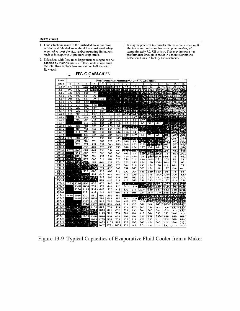
Figure 13-9 Typical Capacities of Evaporative Fluid Cooler from a Maker
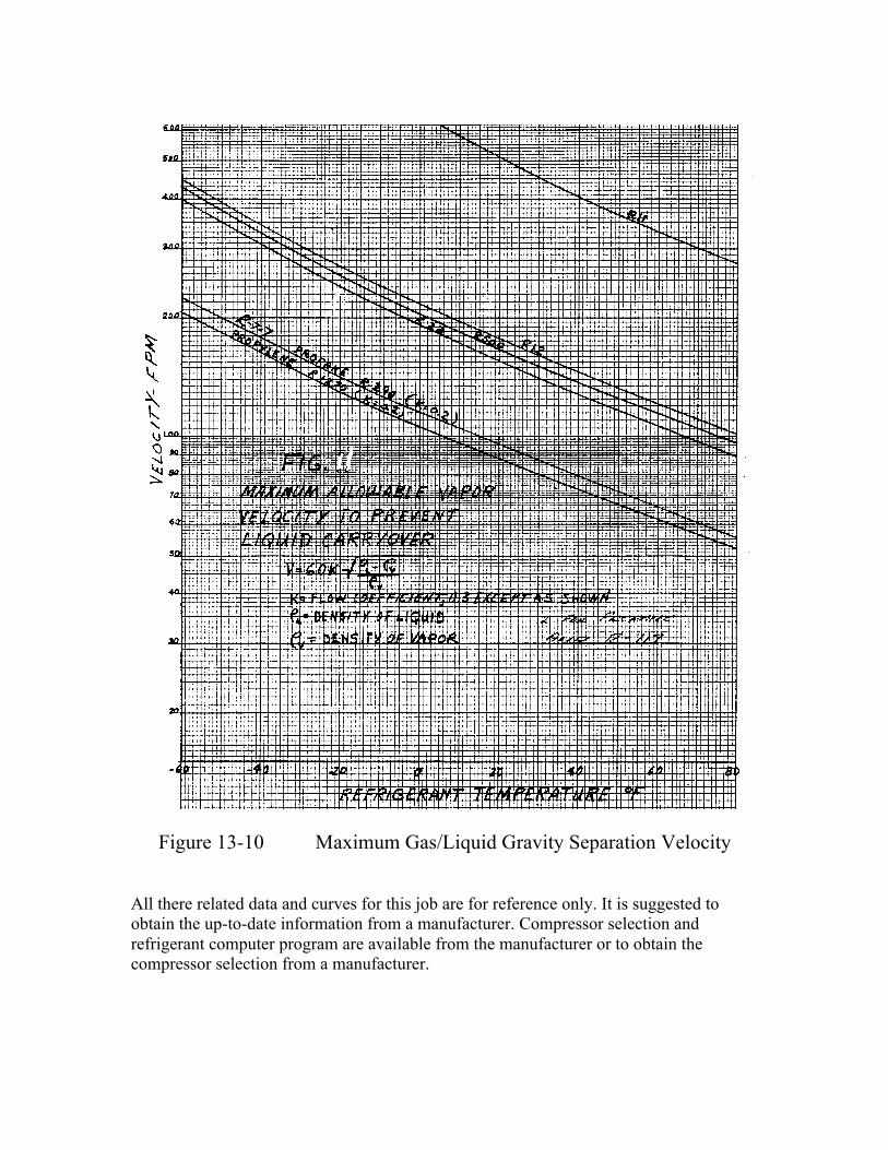
Figure 13-10 Maximum Gas/Liquid Gravity Separation Velocity All there related data and curves for this job are for reference only. It is suggested to obtain the up-to-date information from a manufacturer. Compressor selection and refrigerant computer program are available from the manufacturer or to obtain the compressor selection from a manufacturer.
System Design Logic and Approach: User Load Summary and Temperature Group Assignment: The specification indicated to have one compressor to service one liquid recirculation package and one recirculation package is to be assigned for each temperature group, therefore, it is not economical to have too many recirculation packages. In view of this, users having almost same room design temperature are initially grouped together as the following: (a) User Group No. 1, Design Evaporative Temperature is -50°F: This Group is for the Blast freezing room. Room temperature -40°F. Refrigeration
load is 87 TR. Minimum 6 product coolers shall be used. (b) User Group No. 2, Design Evaporative Temperature is -15°F:
This Group is for Cold Storage Room. Room temperature -3°F. Total refrigeration load is 65 TR, minimum 4 coolers shall be used.
(c) User Group No. 3, Design Evaporative Temperature is 20°F: This Group covers the
following areas: Chilled Room. Room temperature 28°F. Total refrigeration load is 28 TR. Minimum
4 coolers shall be used. Loading Room. Room temperature 32°F. Total refrigeration load is 54 TR.
Minimum 4 coolers shall be used. Ante Room. Room temperature 35°F. Total refrigeration load is 9.2 TR. Minimum 2
coolers shall be used. (d) User Group No. 4, Design Evaporative Temperature of 30°F: This Group covers: Boxing Room. Room temperature 46°F. Total refrigeration load is 15 TR. Minimum
2 coolers shall be used. Deboning Room. Room temperature 43°F. Total refrigeration load is 17.9 TR.
Minimum 4 units shall be used. (e) User Group No. 5. Brine chiller. Design Evaporative Temperature to be determined
later. (f) User Group No. 6. Flake Ice Maker. Design evaporative temperature to be
determined later.
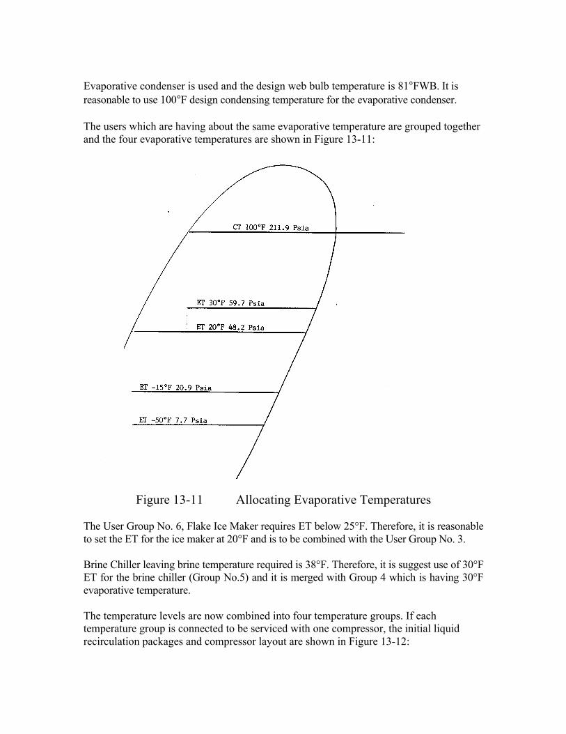
Evaporative condenser is used and the design web bulb temperature is 81°FWB. It is reasonable to use 100°F design condensing temperature for the evaporative condenser. The users which are having about the same evaporative temperature are grouped together and the four evaporative temperatures are shown in Figure 13-11:
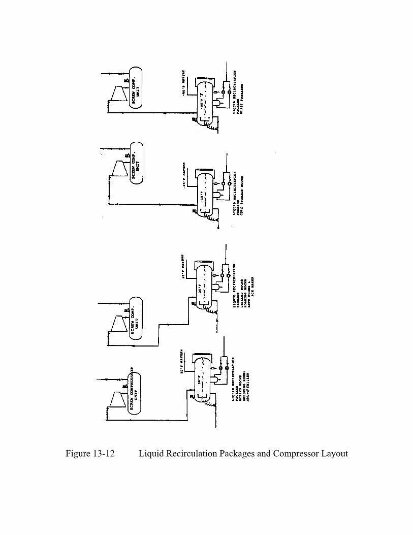
Figure 13-11 Allocating Evaporative Temperatures The User Group No. 6, Flake Ice Maker requires ET below 25°F. Therefore, it is reasonable to set the ET for the ice maker at 20°F and is to be combined with the User Group No. 3. Brine Chiller leaving brine temperature required is 38°F. Therefore, it is suggest use of 30°F ET for the brine chiller (Group No.5) and it is merged with Group 4 which is having 30°F evaporative temperature. The temperature levels are now combined into four temperature groups. If each temperature group is connected to be serviced with one compressor, the initial liquid recirculation packages and compressor layout are shown in Figure 13-12:
Figure 13-12 Liquid Recirculation Packages and Compressor Layout
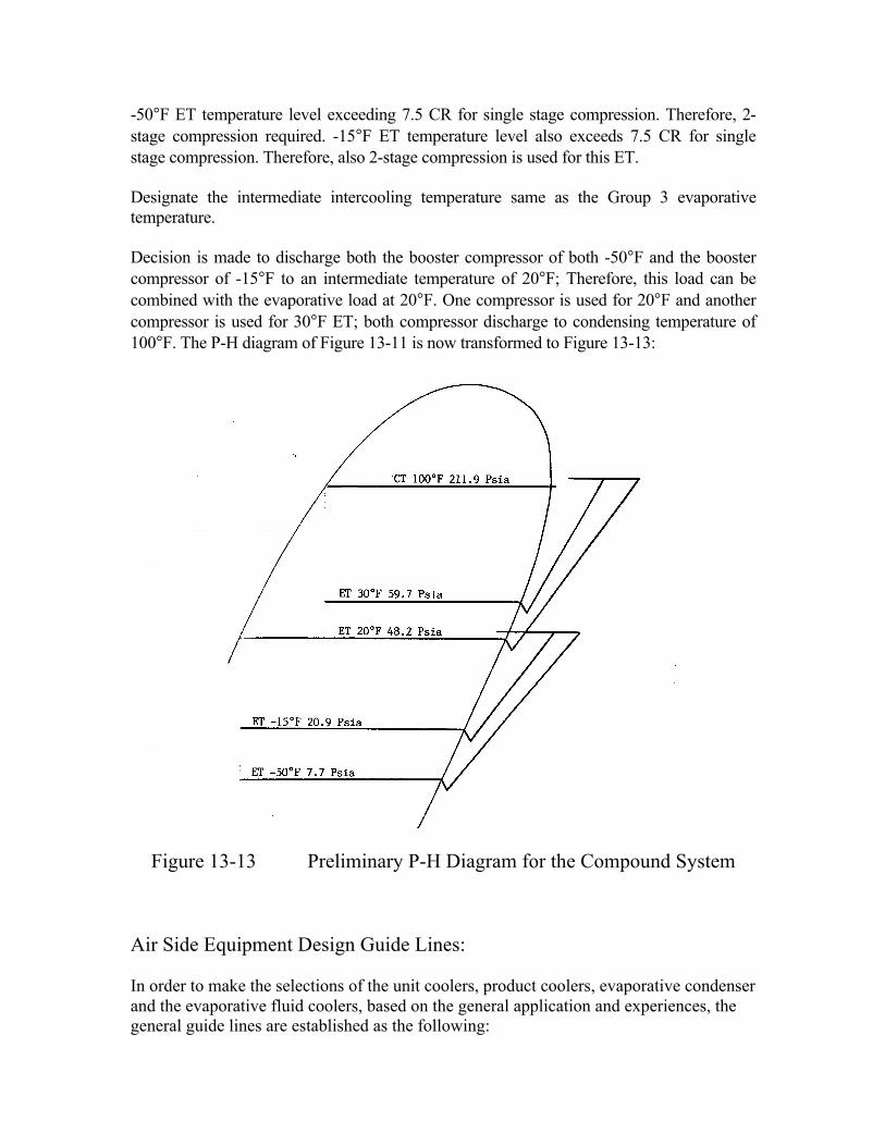
-50°F ET temperature level exceeding 7.5 CR for single stage compression. Therefore, 2-stage compression required. -15°F ET temperature level also exceeds 7.5 CR for single stage compression. Therefore, also 2-stage compression is used for this ET. Designate the intermediate intercooling temperature same as the Group 3 evaporative temperature. Decision is made to discharge both the booster compressor of both -50°F and the booster compressor of -15°F to an intermediate temperature of 20°F; Therefore, this load can be combined with the evaporative load at 20°F. One compressor is used for 20°F and another compressor is used for 30°F ET; both compressor discharge to condensing temperature of 100°F. The P-H diagram of Figure 13-11 is now transformed to Figure 13-13:
Figure 13-13 Preliminary P-H Diagram for the Compound System Air Side Equipment Design Guide Lines: In order to make the selections of the unit coolers, product coolers, evaporative condenser and the evaporative fluid coolers, based on the general application and experiences, the general guide lines are established as the following:
(a) Product coolers are to be used for room temperature below 0°F. (b) Unit coolers are to be used for room temperature above 0°F. (c) 2/3 FPI coil is to be used for -40°F room temperature. (d) 2/4 FPI coil is for room temperature from 0°F to -20°F. (e) 4 FPI coil is to be used for all other room temperature units. (f) All the coolers are to be selected with hot gas defrost.
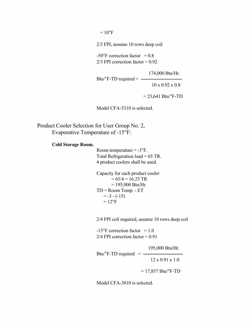
Product and equipment to be used for selection for the project are as the following: Compressor: RW screw Product cooler: CFA series product coolers Unit coolers: HTA series. Evaporative condenser: IDC models. Evaporative Fluid Cooler: EFC-C models. Superheat and Pressure Drops Assumptions: The design pressure drops and superheat for the screw compressors: Minimum external suction: High stage pressure drop: 0.5 Psi Booster pressure drop: 0.5 Psi Minimum external discharge Pressure drop for booster: 0.5 Psi Pressure drop for high stage: 3.0 Psi Minimum suction superheat: 10°F Selection and System Calculations: Product Cooler Selectionn for Users Group No. 1, Evaporative Temperature of -50°F: Blast freezing room. Room temperature = -40°F. Total Refrigeration load = 87 TR. 6 product coolers shall be used. Capacity for each product cooler = 87/6 = 14.5 TR = 174,000 Btu/Hr. TD = Room Temp. - ET = -40 - (-50)
= 10°F 2/3 FPI, assume 10 rows deep coil -50°F correction factor = 0.8 2/3 FPI correction factor = 0.92 174,000 Btu/Hr. Btu/°F-TD required = -------------------------- 10 x 0.92 x 0.8 = 23,641 Btu/°F-TD Model CFA-5310 is selected. Product Cooler Selection for User Group No. 2, Evaporative Temperature of -15°F: Cold Storage Room. Room temperature = -3°F. Total Refrigeration load = 65 TR. 4 product coolers shall be used. Capacity for each product cooler = 65/4 = 16.25 TR = 195,000 Btu/Hr. TD = Room Temp. - ET = -3 - (-15) = 12°F 2/4 FPI coil required, assume 10 rows deep coil -15°F correction factor = 1.0 2/4 FPI correction factor = 0.91 195,000 Btu/Hr. Btu/°F-TD required = ------------------------- 12 x 0.91 x 1.0 = 17,857 Btu/°F-TD Model CFA-3810 is selected.
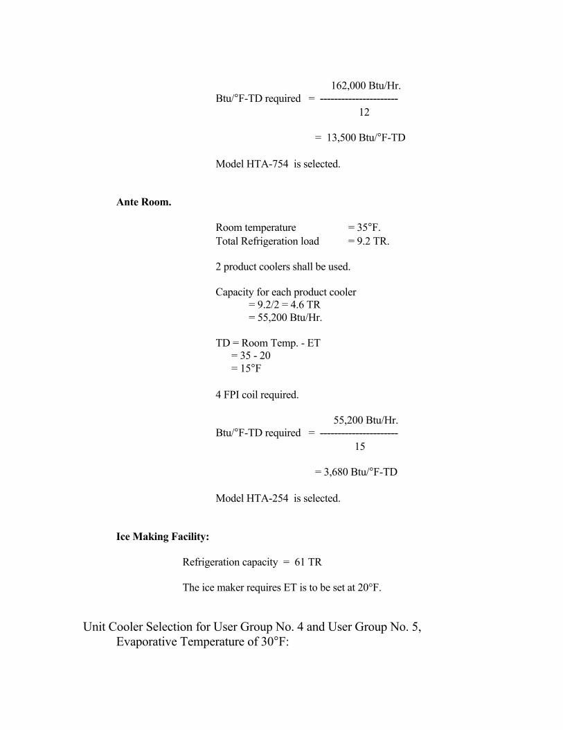
Unit Cooler Slection for User Group No. 3 and User Group No. 6, Evaporative Temperature of 20°F: Chilled Room. Room temperature = 28°F. Total Refrigeration load = 28 TR. 4 product coolers shall be used. Capacity for each product cooler = 28/4 = 7 TR = 84,000 Btu/Hr. TD = Room Temp. - ET = 28 - 20 = 8°F 4 FPI coil required. 84,000 Btu/Hr. Btu/°F-TD required = ---------------------- 8 = 10,500 Btu/°F-TD Model HTA-564 is selected. Loading Room: Room temperature = 32°F. Total Refrigeration load = 54 TR. 4 product coolers shall be used. Capacity for each product cooler = 54/4 = 13.5 TR = 162,000 Btu/Hr. TD = Room Temp. - ET = 32 - 20 = 12°F 4 FPI coil is required.
162,000 Btu/Hr. Btu/°F-TD required = ---------------------- 12 = 13,500 Btu/°F-TD Model HTA-754 is selected. Ante Room. Room temperature = 35°F. Total Refrigeration load = 9.2 TR. 2 product coolers shall be used. Capacity for each product cooler = 9.2/2 = 4.6 TR = 55,200 Btu/Hr. TD = Room Temp. - ET = 35 - 20 = 15°F 4 FPI coil required. 55,200 Btu/Hr. Btu/°F-TD required = ---------------------- 15 = 3,680 Btu/°F-TD Model HTA-254 is selected. Ice Making Facility:
Refrigeration capacity = 61 TR The ice maker requires ET is to be set at 20°F.
Unit Cooler Selection for User Group No. 4 and User Group No. 5, Evaporative Temperature of 30°F:
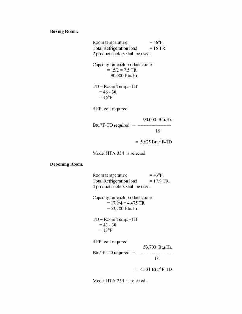
Boxing Room. Room temperature = 46°F. Total Refrigeration load = 15 TR. 2 product coolers shall be used. Capacity for each product cooler = 15/2 = 7.5 TR = 90,000 Btu/Hr. TD = Room Temp. - ET = 46 - 30 = 16°F 4 FPI coil required. 90,000 Btu/Hr. Btu/°F-TD required = ---------------------- 16 = 5,625 Btu/°F-TD Model HTA-354 is selected. Deboning Room. Room temperature = 43°F. Total Refrigeration load = 17.9 TR. 4 product coolers shall be used. Capacity for each product cooler = 17.9/4 = 4.475 TR = 53,700 Btu/Hr. TD = Room Temp. - ET = 43 - 30 = 13°F 4 FPI coil required. 53,700 Btu/Hr. Btu/°F-TD required = ----------------------- 13 = 4,131 Btu/°F-TD Model HTA-264 is selected.
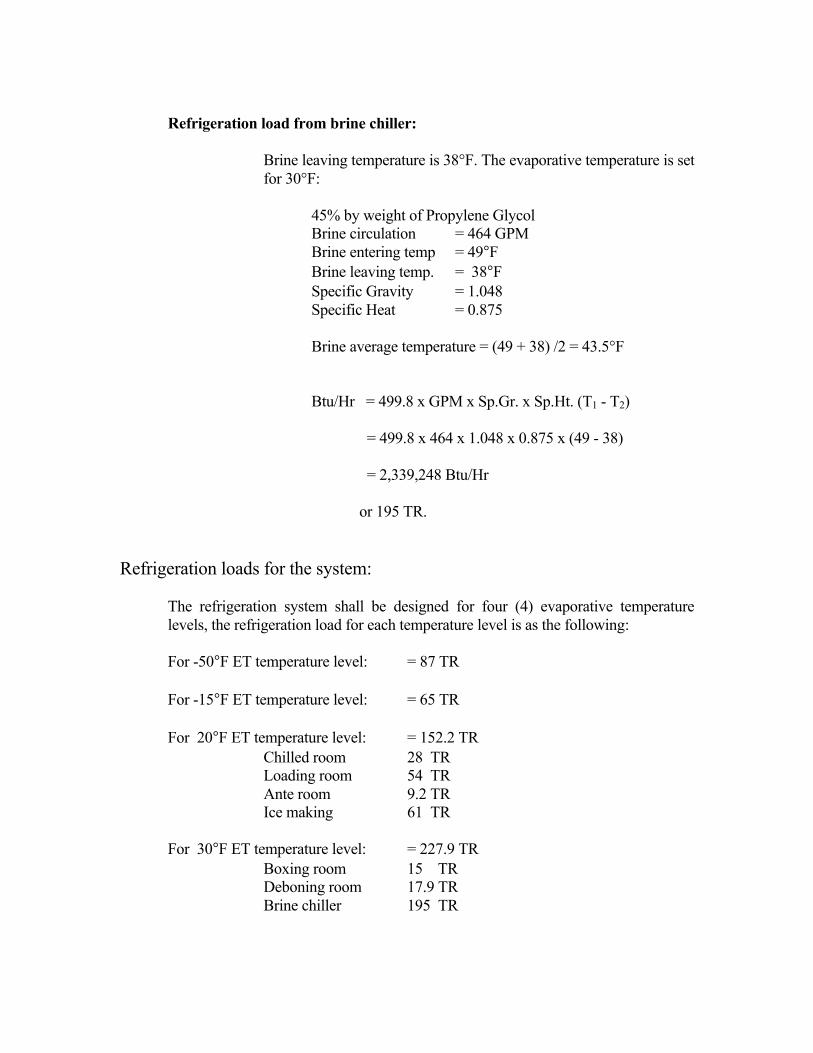
Refrigeration load from brine chiller: Brine leaving temperature is 38°F. The evaporative temperature is set
for 30°F: 45% by weight of Propylene Glycol Brine circulation = 464 GPM Brine entering temp = 49°F Brine leaving temp. = 38°F Specific Gravity = 1.048 Specific Heat = 0.875 Brine average temperature = (49 + 38) /2 = 43.5°F Btu/Hr = 499.8 x GPM x Sp.Gr. x Sp.Ht. (T1 - T2) = 499.8 x 464 x 1.048 x 0.875 x (49 - 38) = 2,339,248 Btu/Hr or 195 TR. Refrigeration loads for the system: The refrigeration system shall be designed for four (4) evaporative temperature
levels, the refrigeration load for each temperature level is as the following: For -50°F ET temperature level: = 87 TR For -15°F ET temperature level: = 65 TR For 20°F ET temperature level: = 152.2 TR Chilled room 28 TR Loading room 54 TR Ante room 9.2 TR Ice making 61 TR For 30°F ET temperature level: = 227.9 TR Boxing room 15 TR Deboning room 17.9 TR Brine chiller 195 TR
System Layout: The system is a compound system, flash type intermediate intercooler is used; intermediate temperature is 20°F. The liquid for ET 20°F and 30°F and the intermediate intercooler is from condenser; the liquid to ET -15°F and -50°F is from the intermediate intercooler. The P-H for the system is formed and as shown in Figure 13-14.
Figure 13-14 P-H Diagram for the Compound System Screw compressors selection: Recap Pressure drops and superheat: Minimum external suction: Suction pressure drop, Booster: 0.5 Psi Suction pressure drop, High Stage: 0.5 Psi Minimum external discharge: Pressure drop for booster: 0.5 Psi Pressure drop for high stage: 3.0 Psi Minimum suction superheat: 10°F
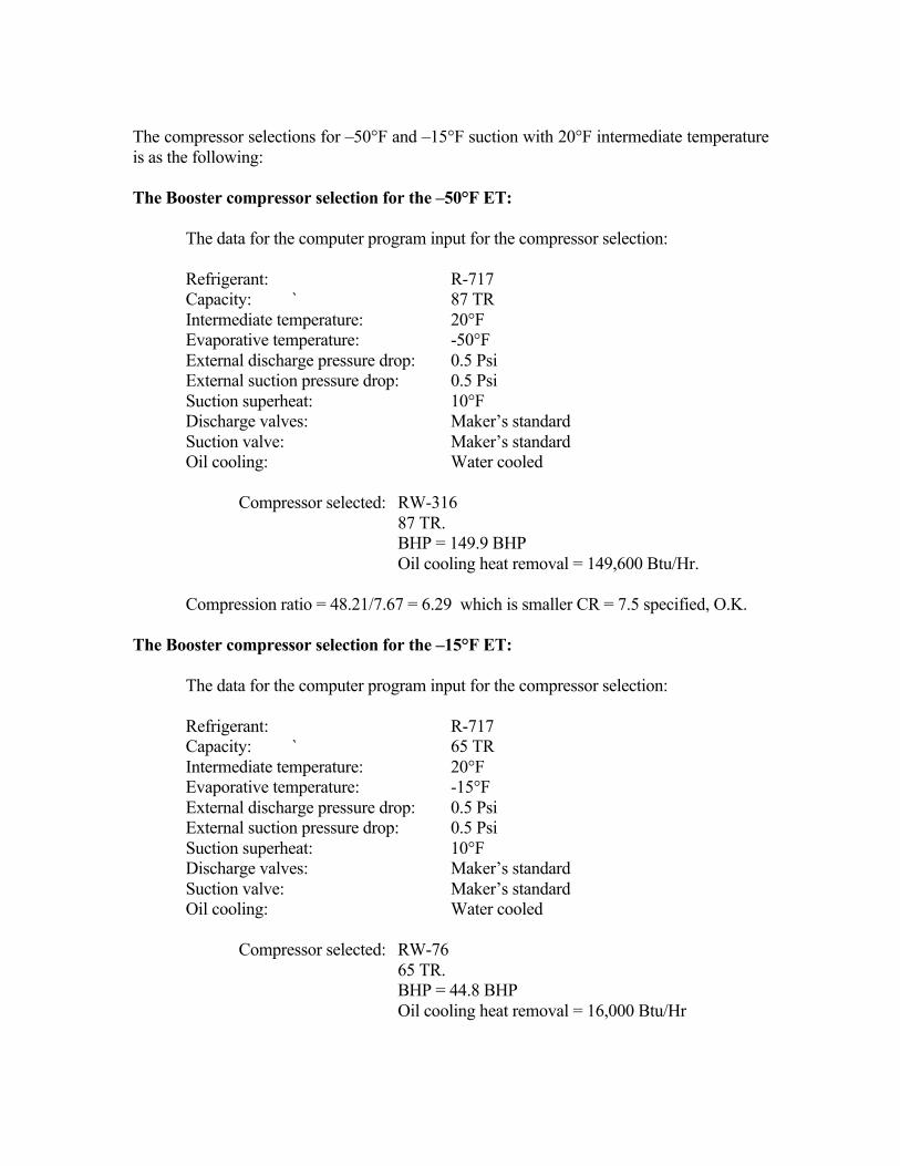
The compressor selections for –50°F and –15°F suction with 20°F intermediate temperature is as the following: The Booster compressor selection for the –50°F ET: The data for the computer program input for the compressor selection: Refrigerant: R-717 Capacity: ` 87 TR Intermediate temperature: 20°F Evaporative temperature: -50°F External discharge pressure drop: 0.5 Psi External suction pressure drop: 0.5 Psi Suction superheat: 10°F Discharge valves: Maker’s standard Suction valve: Maker’s standard Oil cooling: Water cooled Compressor selected: RW-316 87 TR. BHP = 149.9 BHP Oil cooling heat removal = 149,600 Btu/Hr. Compression ratio = 48.21/7.67 = 6.29 which is smaller CR = 7.5 specified, O.K. The Booster compressor selection for the –15°F ET: The data for the computer program input for the compressor selection: Refrigerant: R-717 Capacity: ` 65 TR Intermediate temperature: 20°F Evaporative temperature: -15°F External discharge pressure drop: 0.5 Psi External suction pressure drop: 0.5 Psi Suction superheat: 10°F Discharge valves: Maker’s standard Suction valve: Maker’s standard Oil cooling: Water cooled Compressor selected: RW-76 65 TR. BHP = 44.8 BHP Oil cooling heat removal = 16,000 Btu/Hr
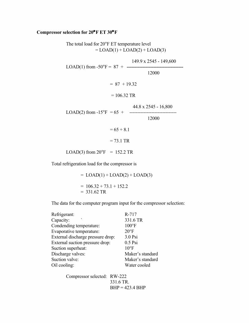
Compressor selection for 20°F ET 30°F The total load for 20°F ET temperature level = LOAD(1) + LOAD(2) + LOAD(3) 149.9 x 2545 - 149,600 LOAD(1) from -50°F = 87 + ------------------------------------ 12000 = 87 + 19.32 = 106.32 TR 44.8 x 2545 - 16,800 LOAD(2) from -15°F = 65 + ------------------------------ 12000 = 65 + 8.1 = 73.1 TR LOAD(3) from 20°F = 152.2 TR Total refrigeration load for the compressor is = LOAD(1) + LOAD(2) + LOAD(3) = 106.32 + 73.1 + 152.2 = 331.62 TR The data for the computer program input for the compressor selection: Refrigerant: R-717 Capacity: ` 331.6 TR Condending temperature: 100°F Evaporative temperature: 20°F External discharge pressure drop: 3.0 Psi External suction pressure drop: 0.5 Psi Suction superheat: 10°F Discharge valves: Maker’s standard Suction valve: Maker’s standard Oil cooling: Water cooled Compressor selected: RW-222 331.6 TR. BHP = 423.4 BHP
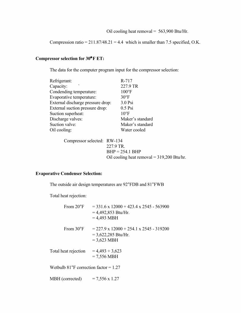
Oil cooling heat removal = 563,900 Btu/Hr. Compression ratio = 211.87/48.21 = 4.4 which is smaller than 7.5 specified, O.K. Compressor selection for 30°F ET: The data for the computer program input for the compressor selection: Refrigerant: R-717 Capacity: ` 227.9 TR Condending temperature: 100°F Evaporative temperature: 30°F External discharge pressure drop: 3.0 Psi External suction pressure drop: 0.5 Psi Suction superheat: 10°F Discharge valves: Maker’s standard Suction valve: Maker’s standard Oil cooling: Water cooled Compressor selected: RW-134 227.9 TR. BHP = 254.1 BHP Oil cooling heat removal = 319,200 Btu/hr. Evaporative Condenser Selection: The outside air design temperatures are 92°FDB and 81°FWB Total heat rejection: From 20°F = 331.6 x 12000 + 423.4 x 2545 - 563900 = 4,492,853 Btu/Hr. = 4,493 MBH From 30°F = 227.9 x 12000 + 254.1 x 2545 - 319200 = 3,622,285 Btu/Hr. = 3,623 MBH Total heat rejection = 4,493 + 3,623 = 7,556 MBH Wetbulb 81°F correction factor = 1.27 MBH (corrected) = 7,556 x 1.27
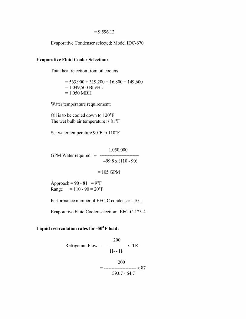
= 9,596.12 Evaporative Condenser selected: Model IDC-670 Evaporative Fluid Cooler Selection: Total heat rejection from oil coolers = 563,900 + 319,200 + 16,800 + 149,600 = 1,049,500 Btu/Hr. = 1,050 MBH Water temperature requirement: Oil is to be cooled down to 120°F The wet bulb air temperature is 81°F Set water temperature 90°F to 110°F 1,050,000 GPM Water required = ------------------------- 499.8 x (110 - 90) = 105 GPM Approach = 90 - 81 = 9°F Range = 110 - 90 = 20°F Performance number of EFC-C condenser - 10.1 Evaporative Fluid Cooler selection: EFC-C-123-4 Liquid recirculation rates for -50°F load: 200 Refrigerant Flow = -------------- x TR H2 - H1 200 = --------------------- x 87 593.7 - 64.7
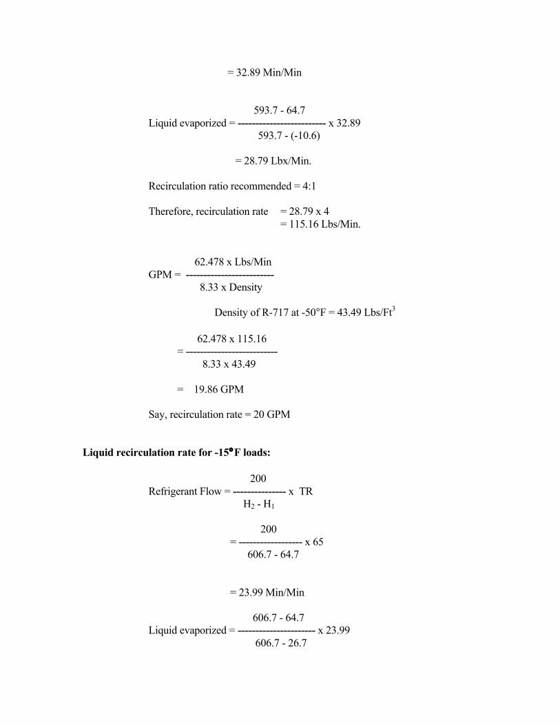
= 32.89 Min/Min 593.7 - 64.7 Liquid evaporized = ------------------------- x 32.89 593.7 - (-10.6) = 28.79 Lbx/Min. Recirculation ratio recommended = 4:1 Therefore, recirculation rate = 28.79 x 4 = 115.16 Lbs/Min. 62.478 x Lbs/Min GPM = ------------------------- 8.33 x Density Density of R-717 at -50°F = 43.49 Lbs/Ft3 62.478 x 115.16 = -------------------------- 8.33 x 43.49 = 19.86 GPM Say, recirculation rate = 20 GPM Liquid recirculation rate for -15°F loads: 200 Refrigerant Flow = --------------- x TR H2 - H1 200 = ------------------ x 65 606.7 - 64.7 = 23.99 Min/Min 606.7 - 64.7 Liquid evaporized = ---------------------- x 23.99 606.7 - 26.7
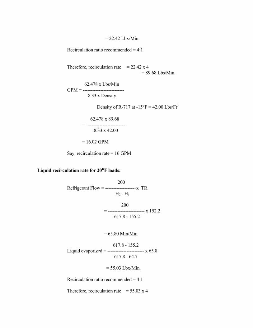
= 22.42 Lbx/Min. Recirculation ratio recommended = 4:1 Therefore, recirculation rate = 22.42 x 4 = 89.68 Lbs/Min. 62.478 x Lbs/Min GPM = -------------------------- 8.33 x Density Density of R-717 at -15°F = 42.00 Lbs/Ft3 62.478 x 89.68 = ----------------------- 8.33 x 42.00 = 16.02 GPM Say, recirculation rate = 16 GPM Liquid recirculation rate for 20°F loads: 200 Refrigerant Flow = ------------------ x TR H2 - H1 200 = ----------------------- x 152.2 617.8 - 155.2 = 65.80 Min/Min 617.8 - 155.2 Liquid evaporized = ----------------------- x 65.8 617.8 - 64.7 = 55.03 Lbx/Min. Recirculation ratio recommended = 4:1 Therefore, recirculation rate = 55.03 x 4
= 220.12 Lbs/Min. 62.478 x Lbs/Min GPM = ------------------------- 8.33 x Density Density of R-717 at 20°F = 40.8 Lbs/Ft3 62.478 x 220.12 = ------------------------ 8.33 x 40.8 = 40.8 GPM Say, recirculation rate = 41 GPM Liquid recirculation rate for 30°F loads: 200 Refrigerant Flow = ----------------- x TR H2 - H1 200 = --------------------- x 227.9 620.5 - 155.2 = 97.96 Min/Min 620.5 - 155.2 Liquid evaporized = -------------------------- x 83.67 620.5 - 75.7 = 55.03 Lbx/Min. Recirculation ratio recommended = 4:1 Therefore, recirculation rate = 83.67 x 4 = 334.68 Lbs/Min. 62.478 x Lbs/Min GPM = ----------------------- 8.33 x Density
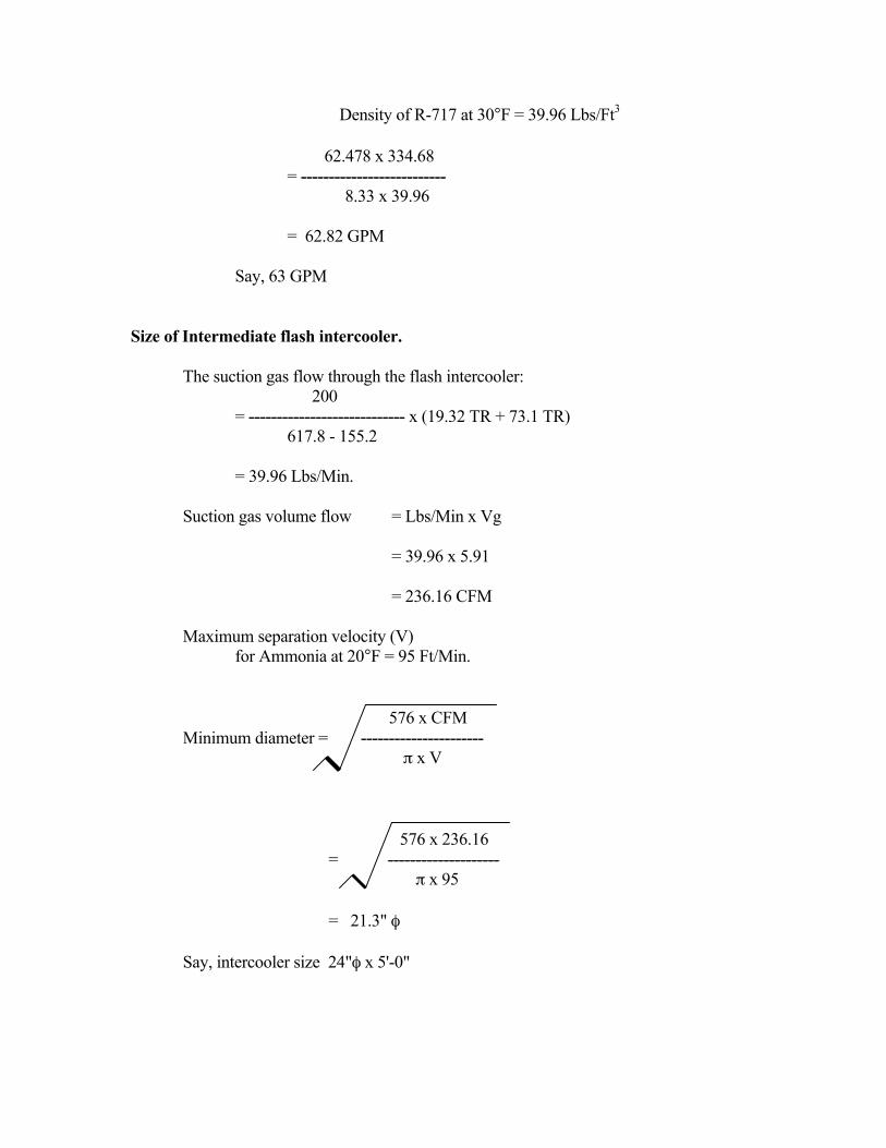
Density of R-717 at 30°F = 39.96 Lbs/Ft3 62.478 x 334.68 = -------------------------- 8.33 x 39.96 = 62.82 GPM Say, 63 GPM Size of Intermediate flash intercooler. The suction gas flow through the flash intercooler: 200 = ---------------------------- x (19.32 TR + 73.1 TR) 617.8 - 155.2 = 39.96 Lbs/Min. Suction gas volume flow = Lbs/Min x Vg = 39.96 x 5.91 = 236.16 CFM Maximum separation velocity (V) for Ammonia at 20°F = 95 Ft/Min. 576 x CFM Minimum diameter = ---------------------- π x V 576 x 236.16 = -------------------- π x 95 = 21.3" φ Say, intercooler size 24"φ x 5'-0"
Suction piping size for -50°F booster compressor suction: Engine room size 80' x 40' x 20'H The booster suction pipe run is from the -50°F liquid recirculation package to the
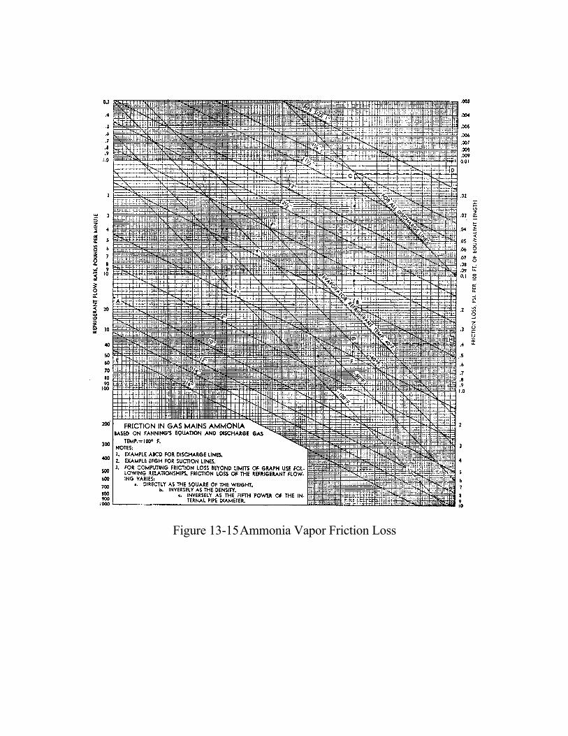
suction of the screw compressor. Estimated pipe run in the engine room = 80' + 40' + 20' = 140' Maximum 5 each of 90° elbows Refrigerant flow = 32.89 Lbs/Min Assume 6"φ suction pipe. 6"φ elbow equivalent pipe run = 9' Total pipe run = 140' + 5 x 9 = 185' Friction loss = 0.06 psi/100' PD = 0.06 x 185/100 = 0.111 Psi Suction external pressure drop allowed is 0.5 Psia. Therefore, the 6"φ pipe is too large. Assume 4"φ suction pipe. 4"φ elbow equivalent pipe run = 6' Total pipe run = 140' + 5 x 6 = 170' Friction loss = 0.24 psi/100' PD = 0.24 x 175/100 = 0.408 Psi Suction external pressure drop allowed is 0.5 Psia. Therefore, the 4"φ pipe is ok.
Figure 13-15 Ammonia Vapor Friction Loss
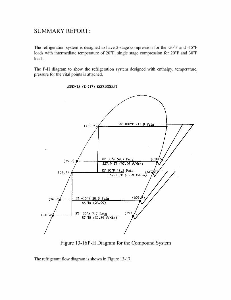
SUMMARY REPORT: The refrigeration system is designed to have 2-stage compression for the -50°F and -15°F loads with intermediate temperature of 20°F; single stage compression for 20°F and 30°F loads. The P-H diagram to show the refrigeration system designed with enthalpy, temperature, pressure for the vital points is attached.
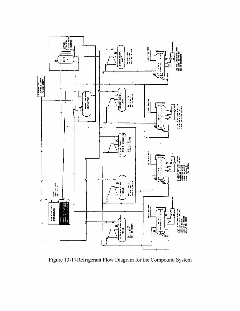
Figure 13-16 P-H Diagram for the Compound System The refrigerant flow diagram is shown in Figure 13-17.
Figure 13-17 Refrigerant Flow Diagram for the Compound System
The Equipment List: Screw compressors: For -50°F temp. : TR 87 Model RW316 Bhp 149.9 For -15°F temp. : TR 65 Model RW-76 Bhp 44.8 For 20°F temp. : TR 331.6 Model RW-222 Bhp 423.4 For 30°F temp. : TR 227.9 Model RW-134 Bhp 254.1 Product Cooler and Unit coolers: Each cooler: For Blast Freezing Room : TR 14.5 Unit Model CFA-5310 For Cold Storage Room : TR 16.25 Unit Model CFA-3810 For Chilled Room : TR 7.0 Unit Model HTA-564 For Loading Room : TR 13.5 Unit Model HTA-254 For Ante Room : TR 4.6 Unit Model HTA-254 For Boxing Room : TR 7.5 Unit Model HTA-354 For Deboning Room : TR 4.475 Unit Model HTA-264 Brine chiller : TR 195 Propylene Glycol : Specific Gravity : 1.048 Specific Heat : 0.875 Ammonia liquid flow : GPM 180 Evaporative condenser : Model IDC-670 Total heat rejection : MBH 7,556 Evaporative Fluid Cooler : Model EFC-C-123-4 Total heat rejection : MBH 1,050 The diameter of the vertical intermediate flash intercooler = 24" Diam. The total TR for each temperature level for liquid recirculation: For -50°F temperature level : 87 TR For -15°F temperature level : 65 TR For 20°F temperature level : 152.2 TR For 30°F temperature level : 227.9 TR
The GPM refrigerant flow of the pump of each liquid recirculation package. For -50°F temperature level: 20 GPM For -15°F temperature level: 16 GPM For 20°F temperature level: 41 GPM For 30°F temperature level: 63 GPM The stand-by screw compressor unit. Model: RW-316 Motor HP: 500 The suction pipe size required for the -50°F screw compressor suction is 4" Diameter. Total BHP of the refrigeration system: For -50°F temp. : TR 87 Model RWB-II-316B Bhp 149.9 For -15°F temp. : TR 65 Model RWB-II-76B Bhp 44.8 For 20°F temp. : TR 152.2 Combined with high stage For 30°F temp. : TR 227.9 Model RWB-II-134 Bhp 254.1 For high stage : TR 331.6 Model RWB-II-222 Bhp 423.4 ----------------- Total BHP: 872.2 Bhp