Case ReportStep-by-Step Esthetic Rehabilitation with Chairside System
Rim Kallala ,1,2,3 Mohamed Habib Chaouch,1 Karim Nasr,4 and Teva Courset4
1Dental Faculty of Monastir, Tunisia2University of Monastir, Research Laboratory of Occlusodontics and Ceramic Prostheses LR16ES15, 5000 Monastir, Tunisia3Department of Dental Faculty at the Dental Faculty of Monastir, Tunisia4Faculty of Dental Surgery and University Hospital, Toulouse, France
Correspondence should be addressed to Rim Kallala; [email protected]
Received 17 February 2021; Revised 11 March 2021; Accepted 16 March 2021; Published 26 March 2021
In modern dentistry, Computer-Aided Design and Manufacturing (CAD/CAM) is a promising technology that allowsfabrication of prosthetic restorations through milling procedures. Over years, with the continuous improvement oftechnology, direct CAD/CAM or “chairside” technology is becoming a widespread approach which offers immediaterehabilitation with long-term rates reported by several studies compared to conventional techniques. All steps are generallycarried out in the dental office during the same treatment session. The present paper is about a healthy female patientwith a decayed 36 tooth which was restored by ceramic onlay using Planmeca’s PlanCAD system. Through the presentclinical case, a detailed protocol of chairside technology would be presented from the digital impression to the millingprocess. It would detail impression steps. It would also highlight especially the virtual design confection of prostheticrestoration using a biogeneric model included in the software. It also illustrated tools which could be used by the dentistto perform the design. Also, some useful tips would be presented in order to perform the confection. On this subject,various studies showed the viability of such technology. To summarize, referring to previous studies, this promisingtechnology allows especially time-saving and patient’s comfort compared to the indirect one.
1. Introduction
In modern dentistry, Computer-Aided Design andManufacturing (CAD/CAM) is a promising technologythat allows fabrication of the prosthetic restorationsthrough milling procedures [1]. Over years, with the con-tinuous improvement of technology, direct CAD/CAM or“chairside” technology is becoming a widespread approachwhich offers immediate rehabilitation. The first one wasintroduced by the CEREC system [1, 2]. Due to this tech-nology, all steps are generally carried out in the dentaloffice during the same treatment session. CAD/CAM sys-tems registered a constantly increasing use in many fieldsof dentistry and allow a completely digital workflow, fromimpression to the final framework, with good clinical reli-ability [2, 3] and excellent patient feedback [4]. The pur-
pose of this paper was to detail the protocol of chairsidesystem and provide a useful evaluation tool, through aclinical case carried out in the dental clinic of the Facultyof Dental Surgery Paul Sabatier Toulouse. The directCAD/CAM system used was Planmeca’s PlanCAD.
2. Clinical Presentation
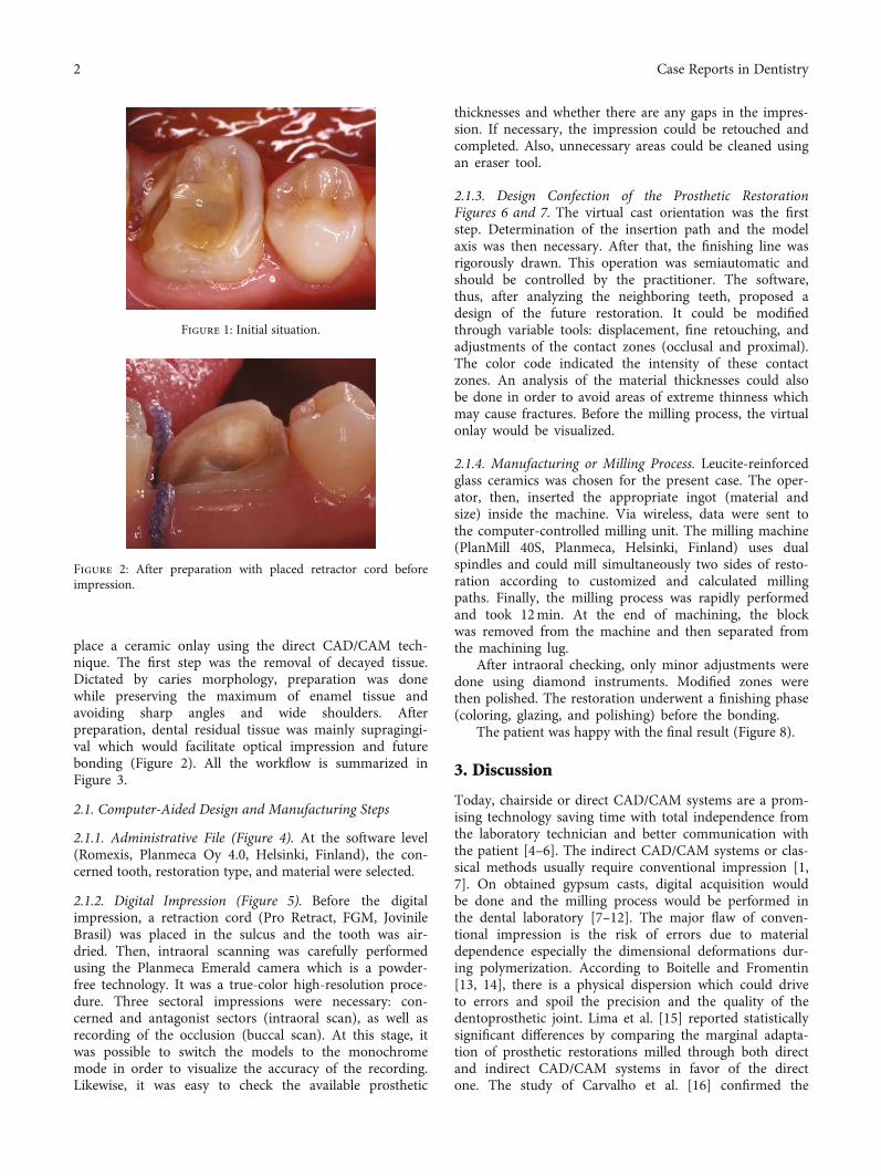
It was a 34-year healthy female patient who consulted forrehabilitation of the left first lower molar (Figure 1). Shehad high esthetic expectations. The clinical examinationshowed good oral hygiene and a decayed and nonvital 36tooth. Radiological examination confirmed a good qualityof root canal filling.
In accordance with the therapeutic gradient and takinginto consideration residual dental tissue, it was decided to
HindawiCase Reports in DentistryVolume 2021, Article ID 5558158, 6 pageshttps://doi.org/10.1155/2021/5558158
place a ceramic onlay using the direct CAD/CAM tech-nique. The first step was the removal of decayed tissue.Dictated by caries morphology, preparation was donewhile preserving the maximum of enamel tissue andavoiding sharp angles and wide shoulders. Afterpreparation, dental residual tissue was mainly supragingi-val which would facilitate optical impression and futurebonding (Figure 2). All the workflow is summarized inFigure 3.
2.1. Computer-Aided Design and Manufacturing Steps
2.1.1. Administrative File (Figure 4). At the software level(Romexis, Planmeca Oy 4.0, Helsinki, Finland), the con-cerned tooth, restoration type, and material were selected.
2.1.2. Digital Impression (Figure 5). Before the digitalimpression, a retraction cord (Pro Retract, FGM, JovinileBrasil) was placed in the sulcus and the tooth was air-dried. Then, intraoral scanning was carefully performedusing the Planmeca Emerald camera which is a powder-free technology. It was a true-color high-resolution proce-dure. Three sectoral impressions were necessary: con-cerned and antagonist sectors (intraoral scan), as well asrecording of the occlusion (buccal scan). At this stage, itwas possible to switch the models to the monochromemode in order to visualize the accuracy of the recording.Likewise, it was easy to check the available prosthetic
thicknesses and whether there are any gaps in the impres-sion. If necessary, the impression could be retouched andcompleted. Also, unnecessary areas could be cleaned usingan eraser tool.
2.1.3. Design Confection of the Prosthetic RestorationFigures 6 and 7. The virtual cast orientation was the firststep. Determination of the insertion path and the modelaxis was then necessary. After that, the finishing line wasrigorously drawn. This operation was semiautomatic andshould be controlled by the practitioner. The software,thus, after analyzing the neighboring teeth, proposed adesign of the future restoration. It could be modifiedthrough variable tools: displacement, fine retouching, andadjustments of the contact zones (occlusal and proximal).The color code indicated the intensity of these contactzones. An analysis of the material thicknesses could alsobe done in order to avoid areas of extreme thinness whichmay cause fractures. Before the milling process, the virtualonlay would be visualized.
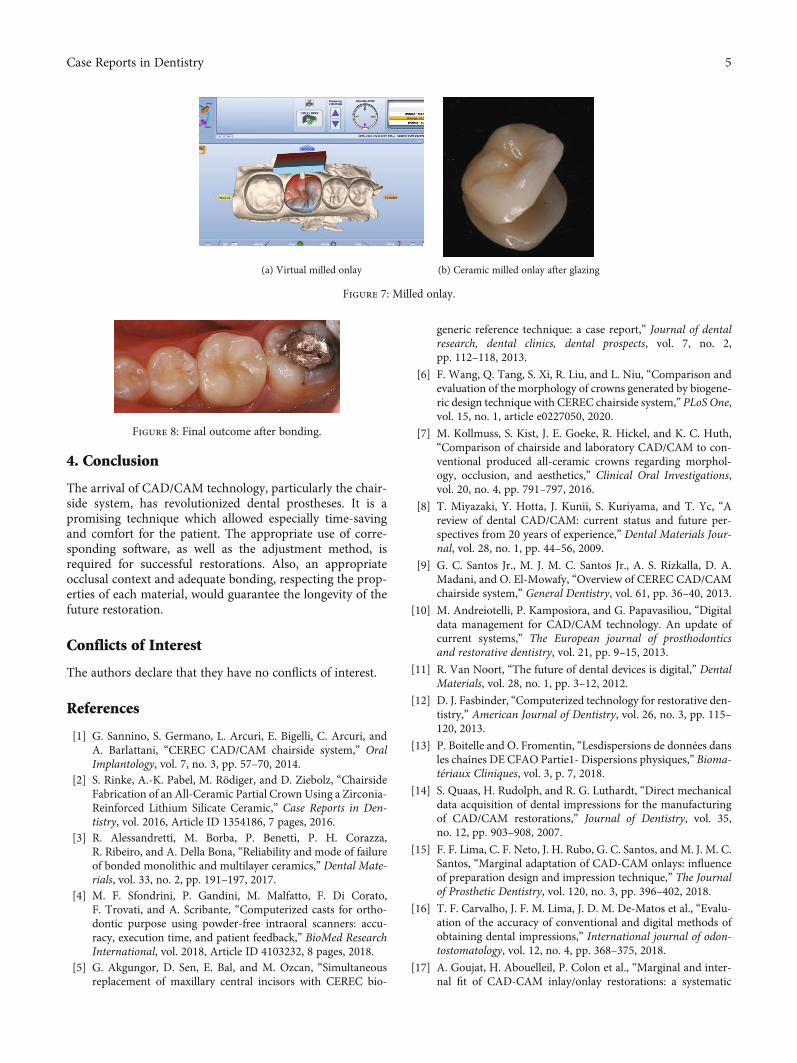
2.1.4. Manufacturing or Milling Process. Leucite-reinforcedglass ceramics was chosen for the present case. The oper-ator, then, inserted the appropriate ingot (material andsize) inside the machine. Via wireless, data were sent tothe computer-controlled milling unit. The milling machine(PlanMill 40S, Planmeca, Helsinki, Finland) uses dualspindles and could mill simultaneously two sides of resto-ration according to customized and calculated millingpaths. Finally, the milling process was rapidly performedand took 12min. At the end of machining, the blockwas removed from the machine and then separated fromthe machining lug.
After intraoral checking, only minor adjustments weredone using diamond instruments. Modified zones werethen polished. The restoration underwent a finishing phase(coloring, glazing, and polishing) before the bonding.
The patient was happy with the final result (Figure 8).
3. Discussion
Today, chairside or direct CAD/CAM systems are a prom-ising technology saving time with total independence fromthe laboratory technician and better communication withthe patient [4–6]. The indirect CAD/CAM systems or clas-sical methods usually require conventional impression [1,7]. On obtained gypsum casts, digital acquisition wouldbe done and the milling process would be performed inthe dental laboratory [7–12]. The major flaw of conven-tional impression is the risk of errors due to materialdependence especially the dimensional deformations dur-ing polymerization. According to Boitelle and Fromentin[13, 14], there is a physical dispersion which could driveto errors and spoil the precision and the quality of thedentoprosthetic joint. Lima et al. [15] reported statisticallysignificant differences by comparing the marginal adapta-tion of prosthetic restorations milled through both directand indirect CAD/CAM systems in favor of the directone. The study of Carvalho et al. [16] confirmed the
Figure 1: Initial situation.
Figure 2: After preparation with placed retractor cord beforeimpression.
2 Case Reports in Dentistry
superiority of digital techniques in comparison with con-ventional methods. However, the systematic review ofGoujat et al. [17] reported that the marginal adaptationobtained was satisfactory without statistically significantdifferences between the two techniques. The meta-analysis could not be performed as findings were heteroge-neous. For Aswani et al. [18], variable results werereported depending on the systems used. According toEnder and Mehl [19], optical impressions provided levelsof accuracy in the same order as those of conventionalimpressions. Some studies [19–21] reported statisticallynot significant differences between the impression tech-niques. Indeed, Boitelle and Fromentin [13] reported thatphysical dispersion exists also for the direct CAD/CAMtechnique. It could be linked to different interactions ofthe light beam and dental tissues. Besides, errors couldbe due to the oral environment, to external environments(brightness of the treatment room), and to the manipula-tion also [13]. The study of Kuhr et al. [21] pointed outthat conventional casts seem to be similar to digitalimpression models. But secondary areas, such as grooves
and pits, were better reproduced in gypsum models. Tosum up, chairside technology allows especially saving time[16] as digital scanning is easy and rapid. Besides, there isno need to disinfect and clean dental impressions eitherwaiting cast pouring.
On the other hand, the restoration occlusal design isconsidered among the most important conditions for anoptimal outcome, through harmonic relation to adjacentteeth and interference-free occlusal contacts [22]. InCAD/CAM technology, it is adjusted thanks to an algo-rithmic equation which involves a library of intact toothmorphology integrated into the software called the bio-generic model [6, 23]. In this regard, several studies havebeen carried out comparing the morphologies of naturalteeth and those given by the biogeneric models and haveconcluded with similar morphologies [7, 24, 25]. Enderet al. concluded that according to experts, obtained mor-phologies were natural looking [24]. Others comparedthe morphology of natural teeth and those of wax-upsmade by laboratory technicians in favor of the biogenericmodel [26, 27].
Otherwise, in the present clinical situation, the toothcould be reconstructed with a fiber post and core followedby a crown.
Nevertheless, this promising technology has some limita-tions: The first is the high cost which requires huge invest-ment. Then, as it provides monolithic restorations, theesthetic outcome would be better using a stratification tech-nique which allows characterization in the frameworkdepending on the laboratory technician’s skills and perfor-mances [26]. Tuncel reported statistically significant differ-ences in terms of translucency between monolithic zirconiaand framework zirconia [29].
Model orientation and axis determination
Biogeneric model
Drawing the finish line
Modifications onproposed morphology if
necessary
Thickness and contactscontrol
Validation
Bonding
Characterizationglazing
Intra oralchecking
Milling
Designconfection
Opticalimpression
Dentalpreparation
Figure 3: Chairside workflow.
Figure 4: The administrative file.
3Case Reports in Dentistry
(a) True-color virtual model (b) Virtual model in monochrome mode
(c) Virtual antagonist model (d) Confronted virtual models
Figure 5: Virtual models obtained after digital impression.
(a) Finishing line drawing (b) The proposed design
(c) After modifications (d) Visualization of proximal and occlusal contacts
(e) Color codes for the material thickness
Figure 6: Design confection of the future restoration.
4 Case Reports in Dentistry
4. Conclusion
The arrival of CAD/CAM technology, particularly the chair-side system, has revolutionized dental prostheses. It is apromising technique which allowed especially time-savingand comfort for the patient. The appropriate use of corre-sponding software, as well as the adjustment method, isrequired for successful restorations. Also, an appropriateocclusal context and adequate bonding, respecting the prop-erties of each material, would guarantee the longevity of thefuture restoration.
Conflicts of Interest
The authors declare that they have no conflicts of interest.
References
[1] G. Sannino, S. Germano, L. Arcuri, E. Bigelli, C. Arcuri, andA. Barlattani, “CEREC CAD/CAM chairside system,” OralImplantology, vol. 7, no. 3, pp. 57–70, 2014.
[2] S. Rinke, A.-K. Pabel, M. Rödiger, and D. Ziebolz, “ChairsideFabrication of an All-Ceramic Partial Crown Using a Zirconia-Reinforced Lithium Silicate Ceramic,” Case Reports in Den-tistry, vol. 2016, Article ID 1354186, 7 pages, 2016.
[3] R. Alessandretti, M. Borba, P. Benetti, P. H. Corazza,R. Ribeiro, and A. Della Bona, “Reliability and mode of failureof bonded monolithic and multilayer ceramics,” Dental Mate-rials, vol. 33, no. 2, pp. 191–197, 2017.
[4] M. F. Sfondrini, P. Gandini, M. Malfatto, F. Di Corato,F. Trovati, and A. Scribante, “Computerized casts for ortho-dontic purpose using powder-free intraoral scanners: accu-racy, execution time, and patient feedback,” BioMed ResearchInternational, vol. 2018, Article ID 4103232, 8 pages, 2018.
[5] G. Akgungor, D. Sen, E. Bal, and M. Ozcan, “Simultaneousreplacement of maxillary central incisors with CEREC bio-
generic reference technique: a case report,” Journal of dentalresearch, dental clinics, dental prospects, vol. 7, no. 2,pp. 112–118, 2013.
[6] F. Wang, Q. Tang, S. Xi, R. Liu, and L. Niu, “Comparison andevaluation of the morphology of crowns generated by biogene-ric design technique with CEREC chairside system,” PLoS One,vol. 15, no. 1, article e0227050, 2020.
[7] M. Kollmuss, S. Kist, J. E. Goeke, R. Hickel, and K. C. Huth,“Comparison of chairside and laboratory CAD/CAM to con-ventional produced all-ceramic crowns regarding morphol-ogy, occlusion, and aesthetics,” Clinical Oral Investigations,vol. 20, no. 4, pp. 791–797, 2016.
[8] T. Miyazaki, Y. Hotta, J. Kunii, S. Kuriyama, and T. Yc, “Areview of dental CAD/CAM: current status and future per-spectives from 20 years of experience,” Dental Materials Jour-nal, vol. 28, no. 1, pp. 44–56, 2009.
[9] G. C. Santos Jr., M. J. M. C. Santos Jr., A. S. Rizkalla, D. A.Madani, and O. El-Mowafy, “Overview of CEREC CAD/CAMchairside system,” General Dentistry, vol. 61, pp. 36–40, 2013.
[10] M. Andreiotelli, P. Kamposiora, and G. Papavasiliou, “Digitaldata management for CAD/CAM technology. An update ofcurrent systems,” The European journal of prosthodonticsand restorative dentistry, vol. 21, pp. 9–15, 2013.
[11] R. Van Noort, “The future of dental devices is digital,” DentalMaterials, vol. 28, no. 1, pp. 3–12, 2012.
[12] D. J. Fasbinder, “Computerized technology for restorative den-tistry,” American Journal of Dentistry, vol. 26, no. 3, pp. 115–120, 2013.
[13] P. Boitelle and O. Fromentin, “Lesdispersions de données dansles chaînes DE CFAO Partie1- Dispersions physiques,” Bioma-tériaux Cliniques, vol. 3, p. 7, 2018.
[14] S. Quaas, H. Rudolph, and R. G. Luthardt, “Direct mechanicaldata acquisition of dental impressions for the manufacturingof CAD/CAM restorations,” Journal of Dentistry, vol. 35,no. 12, pp. 903–908, 2007.
[15] F. F. Lima, C. F. Neto, J. H. Rubo, G. C. Santos, and M. J. M. C.Santos, “Marginal adaptation of CAD-CAM onlays: influenceof preparation design and impression technique,” The Journalof Prosthetic Dentistry, vol. 120, no. 3, pp. 396–402, 2018.
[16] T. F. Carvalho, J. F. M. Lima, J. D. M. De-Matos et al., “Evalu-ation of the accuracy of conventional and digital methods ofobtaining dental impressions,” International journal of odon-tostomatology, vol. 12, no. 4, pp. 368–375, 2018.
[17] A. Goujat, H. Abouelleil, P. Colon et al., “Marginal and inter-nal fit of CAD-CAM inlay/onlay restorations: a systematic
(a) Virtual milled onlay (b) Ceramic milled onlay after glazing
Figure 7: Milled onlay.
Figure 8: Final outcome after bonding.
5Case Reports in Dentistry
review of in vitro studies,” The Journal of Prosthetic Dentistry,vol. 121, no. 4, pp. 590–597.e3, 2019.
[18] K. Aswani, S. Wankhade, A. Khalikar, and S. Deogade, “Accu-racy of an intraoral digital impression: a review,” The Journalof Indian Prosthodontic Society, vol. 20, no. 1, pp. 27–37, 2020.
[19] A. Ender and A. Mehl, “Full arch scans: conventional versusdigital impressions-an in-vitro study,” International Journalof Computerized Dentistry, vol. 14, no. 1, pp. 11–21, 2011.
[20] T. Abdel-Azim, K. Rogers, E. Elathamna, A. Zandinejad,M. Metz, and D. Morton, “Comparison of the marginal fit oflithium disilicate crowns fabricated with CAD/CAM technol-ogy by using conventional impressions and two intraoral dig-ital scanners,” The Journal of Prosthetic Dentistry, vol. 114,no. 4, pp. 554–559, 2015.
[21] F. Kuhr, A. Schmidt, P. Rehmann, and B. Wöstmann, “A newmethod for assessing the accuracy of full arch impressions inpatients,” Journal of Dentistry, vol. 55, pp. 68–74, 2016.
[22] Y. Arslan, S. K. Nemli, M. B. Güngör, E. Tamam, andH. Yılmaz, “Evaluation of biogeneric design techniques withCEREC CAD/CAM system,” The Journal of Advanced Pros-thodontics, vol. 7, no. 6, pp. 431–436, 2015.
[23] A. Mehl, V. Blanz, and R. Hickel, “Biogeneric tooth: a newmathematical representation for tooth morphology in lowerfirst molars,” European Journal of Oral Sciences, vol. 113,no. 4, pp. 333–340, 2005.
[24] A. Ender, W. H. Mörmann, and A. Mehl, “Efficiency of amathematical model in generating CAD/CAM-partial crownswith natural tooth morphology,” Clinical Oral Investigations,vol. 15, no. 2, pp. 283–289, 2011.
[25] R. Zhang, Q. Ding, Y. Sun, L. Zhang, and Q. Xie, “Assessmentof CAD-CAM zirconia crowns designed with 2 differentmethods: a self-controlled clinical trial,” The Journal of Pros-thetic Dentistry, vol. 120, no. 5, pp. 686–692, 2018.
[26] C. Ellerbrock and B. Kordass, “Comparison of computer gen-erated occlusal surfaces with functionally waxed-on surfaces,”International Journal of Computerized Dentistry, vol. 14, no. 1,pp. 23–31, 2011.
[27] M. Kollmuss, F.-M. Jakob, H.-G. Kirchner, N. Ilie, R. Hickel,and K. C. Huth, “Comparison of biogenerically reconstructedand waxed-up complete occlusal surfaces with respect to theoriginal tooth morphology,” Clinical Oral Investigations,vol. 17, no. 3, pp. 851–857, 2013.
[28] J. Carames, L. T. Suinaga, Y. C. P. Yu, A. Pérez, and M. Kang,“Clinical advantages and limitations of monolithic zirconiarestorations full arch implant supported reconstruction: caseseries,” International Journal of Dentistry, vol. 2015, ArticleID 392496, 7 pages, 2015.
[29] “Evaluation of translucency of monolithic zirconia and frame-work zirconia materials,” The Journal of Advanced Prostho-dontics, vol. 8, no. 3, pp. 181–186, 2016.