17
Case Studies

Case Studies
2
Content
Flowcode and MIAC controlling time
MIAC RC5 Remote Control
MIAC Controlled Door Lock
MIAC PLC - Mini Hydro Generator
MIAC Controlled Underfloor Heating
Using MIAC to Keep Us Safe
MIAC Manages Emergency Power
3
5
7
9
11
13
15

3
Flowcode and MIAC Controlling Time
Smith of Derby’s engineers used an 8 bit PIC MIAC unit when the old mercury filled triggering system for a carillon had to be replaced for health and safety reasons (a carillon is a musical instrument that is typically housed in the bell tower of a church or municipal building). The MIAC offered a reliable control unit; so all the team at Smith of Derby had to do was interface and program the control software.
Flowcode and MIAC users and bespoke clock manufacturers and repairers, Smith of Derby shared a wonderful example of how the two can work hand-in-hand to allow manufacturers to develop quick solutions for market needs and use the hardware in product development too.

4
In this particular example from the Parish church of St George in Lower Brailes, Oxfordshire, Smith of Derby used a MIAC when the old mercury filled triggering system for a carillon had to be replace for health and safety reasons. Flowcode lends itself so well to controlling algorithms, and so the 150+ year old giant music box was able to be updated.
The use of Flowcode, combined with the MIAC unit saved the customer a significant amount in development costs.
Engineers from Smith of Derby provided the circuitry for the interface used in this project, alongside some example code from the Flowcode program used, as can be seen below.
Smith of Derby have great experience of working across a number of wide ranging projects including a number of church heritage projects throughout the globe. They offer a wide range of services covering all aspects of restoration, installation, maintenance and repair work related to church clocks, public clocks, feature, turret and tower clocks.
Among their extensive portfolio of exterior public clocks, they originally installed the cathedral clock in St Paul’s Cathedral in London and maintain it to this day.
Smith of Derby are not only users of the MIAC, but also of Flowcode and other Matrix products: The Smith of Derby, patent applied PAR-100 Pendulum Regulator System provides automated time adjustment for weight driven tower and Church clocks. The PAR-100 prevents the clock from drifting out of time and is particularly useful where automatic winding has been fitted. The auto winding system replaces the need for regular hand-winding and the PAR regulates the time.
By setting the clock to run faster than normal, the PAR 100 operates by periodically stopping the pendulum whilst real time “catches up” with indicated clock time. This constant re-synchronisation keeps the clock to within a very close tolerance of real time day on day, week on week and so on.
5
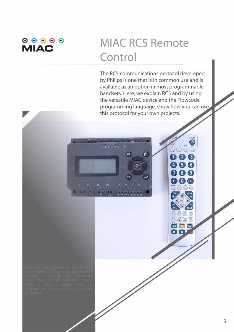
MIAC RC5 Remote ControlThe RC5 communications protocol developed by Philips is one that is in common use and is available as an option in most programmable handsets. Here, we explain RC5 and by using the versatile MIAC device and the Flowcode programming language, show how you can use this protocol for your own projects.
Transmission is relatively slow. Each bit has a typical period of 1778μs – with large variations tolerated. A standard RC5 transmission contains 14 bits (nearly 25ms per message). There are tables of default devices and functions associated with the information transmitted.
6
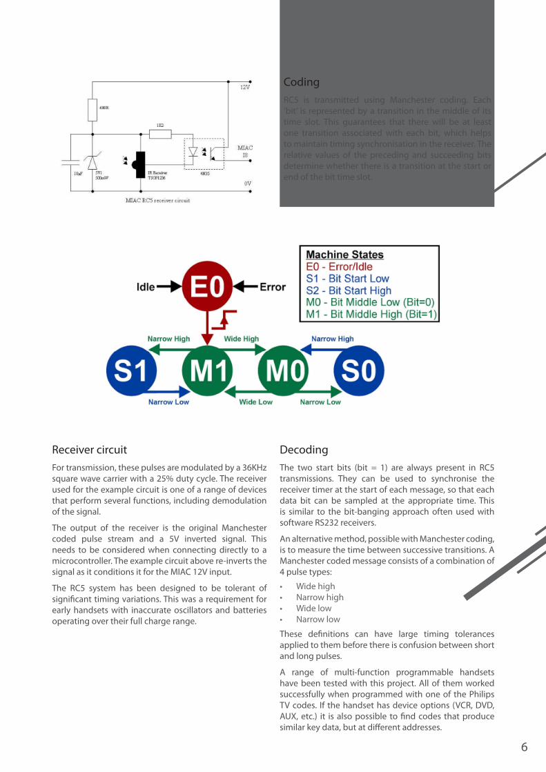
RC5 is transmitted using Manchester coding. Each ‘bit’ is represented by a transition in the middle of its time slot. This guarantees that there will be at least one transition associated with each bit, which helps to maintain timing synchronisation in the receiver. The relative values of the preceding and succeeding bits determine whether there is a transition at the start or end of the bit time slot.
For transmission, these pulses are modulated by a 36KHz square wave carrier with a 25% duty cycle. The receiver used for the example circuit is one of a range of devices that perform several functions, including demodulation of the signal.
The output of the receiver is the original Manchester coded pulse stream and a 5V inverted signal. This needs to be considered when connecting directly to a microcontroller. The example circuit above re-inverts the signal as it conditions it for the MIAC 12V input.
The RC5 system has been designed to be tolerant of significant timing variations. This was a requirement for early handsets with inaccurate oscillators and batteries operating over their full charge range.
The two start bits (bit = 1) are always present in RC5 transmissions. They can be used to synchronise the receiver timer at the start of each message, so that each data bit can be sampled at the appropriate time. This is similar to the bit-banging approach often used with software RS232 receivers.
An alternative method, possible with Manchester coding, is to measure the time between successive transitions. A Manchester coded message consists of a combination of 4 pulse types:
• Wide high • Narrow high • Wide low • Narrow low
These definitions can have large timing tolerances applied to them before there is confusion between short and long pulses.
A range of multi-function programmable handsets have been tested with this project. All of them worked successfully when programmed with one of the Philips TV codes. If the handset has device options (VCR, DVD, AUX, etc.) it is also possible to find codes that produce similar key data, but at different addresses.
Coding
DecodingReceiver circuit

7
MIAC Controlled Door LockMany people don’t realise the MIACs potential for real world, everyday applications. Here, we show how the versatile MIAC device can be used to quickly and easily develop an electronic door lock with password security, and all running at 12V!
The 12V operation of the MIAC makes it compatible with a wide range of domestic and industrial alarm/ security components. A low cost electronically released lock mechanism, and door contact reed switch from a standard alarm system, can be connected directly to a MIAC to provide access control.

8
A system of this type can be configured in a number of different ways. In this instance the MIAC is positioned close to the locked door to provide the display and keypad at the access point.
The door can be unlocked automatically by entering the correct key sequence on the keypad. Alternatively, the sounder can be used to attract attention by providing a ‘doorbell’ option, allowing the door to be unlocked manually from the secure side.
Program loopThe program is written as a single loop with macro calls to handle the individual system elements (door sensor, keypad, lock, sounder, display).
Operating statesThe current state of each system element is stored in global variables. These can be used by other elements to calculate their required states and actions.
Example: If the door lock state is ‘Locked’, but the door sensor state is ‘Open’, the sounder should go to its ‘Alarm’ state.
TimersSome of the system operations require relatively long time delays (several seconds). Generating these delay functions, without suspending operation of other functions, is achieved by implementing them as loop counters. These rely on the continuous cycling of the program to provide the main time base.
System statesThe main requirements of the system are:
• Momentarily release the door lock when specific conditions are met
• Confirm that the door is not opened when it is expected to be closed
The individual system components can be in numerous states including ‘door sensor’, ‘lock’, ‘keypad’, ‘sounder’, etc.
This project can be combined with the code from the previous RC5 article to add remote access control functionality to the system. A simple remote lock release function could be implemented in a similar way to the disarm button (forcing a pseudo correct code condition in the keypad state).
9
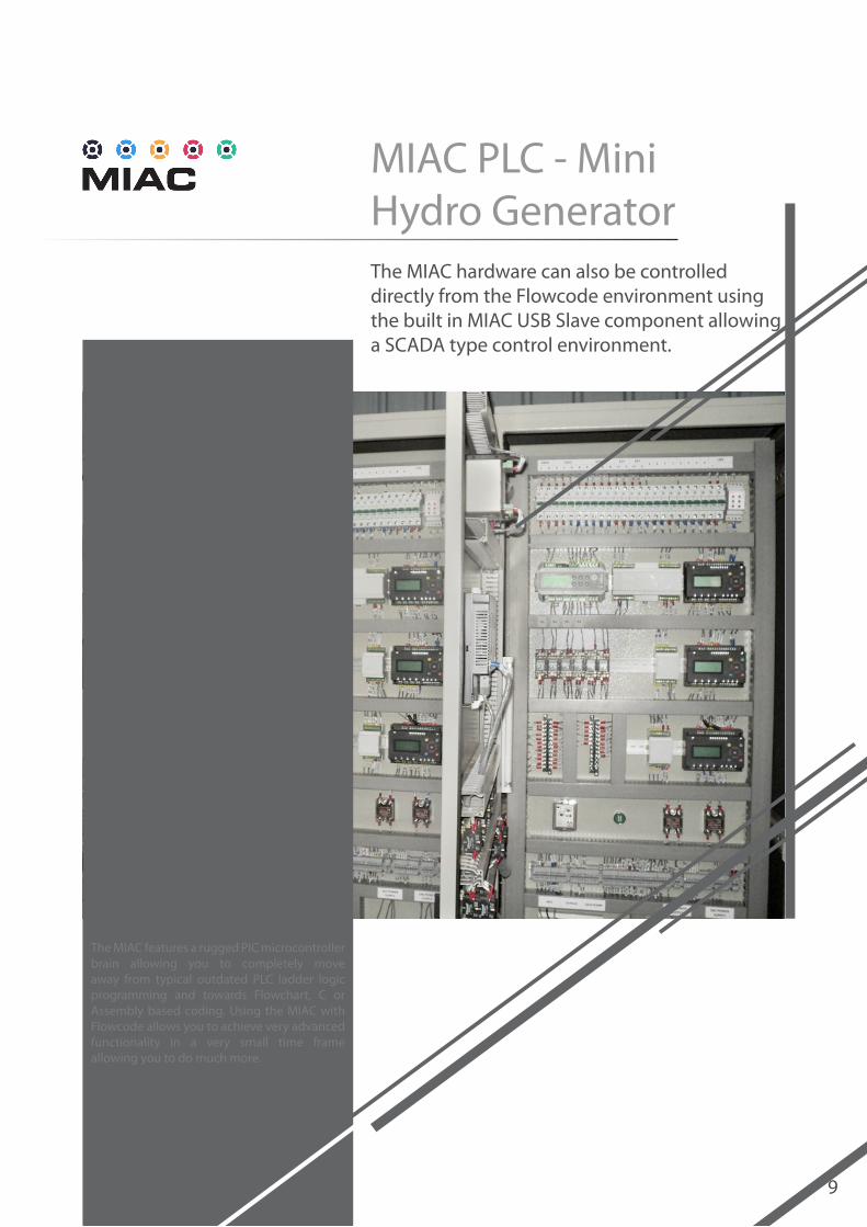
MIAC PLC - Mini Hydro GeneratorThe MIAC hardware can also be controlled directly from the Flowcode environment using the built in MIAC USB Slave component allowing a SCADA type control environment.
The MIAC features a rugged PIC microcontroller brain allowing you to completely move away from typical outdated PLC ladder logic programming and towards Flowchart, C or Assembly based coding. Using the MIAC with Flowcode allows you to achieve very advanced functionality in a very small time frame allowing you to do much more.
10
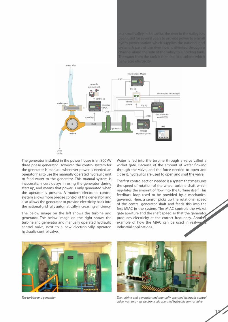
In a small valley in Sri Lanka, the river in the valley has been used for several years to provide power to a small hydro power station which supplies the national grid system. A part of the river flow is diverted through a channel along the side of the valley to a holding tank. The water from the tank is then fed to a turbine which generates electricity.
The generator installed in the power house is an 800kW three phase generator. However, the control system for the generator is manual: whenever power is needed an operator has to use the manually operated hydraulic unit to feed water to the generator. This manual system is inaccurate, incurs delays in using the generator during start up, and means that power is only generated when the operator is present. A modern electronic control system allows more precise control of the generator, and also allows the generator to provide electricity back into the national grid fully automatically increasing efficiency.
The below image on the left shows the turbine and generator. The below image on the right shows the turbine and generator and manually operated hydraulic control valve, next to a new electronically operated hydraulic control valve.
Water is fed into the turbine through a valve called a wicket gate. Because of the amount of water flowing through the valve, and the force needed to open and close it, hydraulics are used to open and shut the valve.
The first control section needed is a system that measures the speed of rotation of the wheel turbine shaft which regulates the amount of flow into the turbine itself. This feedback loop used to be provided by a mechanical governor. Here, a sensor picks up the rotational speed of the central generator shaft and feeds this into the first MIAC in the system. The MIAC controls the wicket gate aperture and the shaft speed so that the generator produces electricity at the correct frequency. Another example of how the MIAC can be used in real-world industrial applications.
The turbine and generator The turbine and generator and manually operated hydraulic control valve, next to a new electronically operated hydraulic control valve

11
MIAC Controlled Underfloor HeatingHere’s an example of how Flowcode can be used for home applications. In this scenario, plastic piping has been placed throughout the floors of a house, and a boiler and some plumbing connections have been purchased.
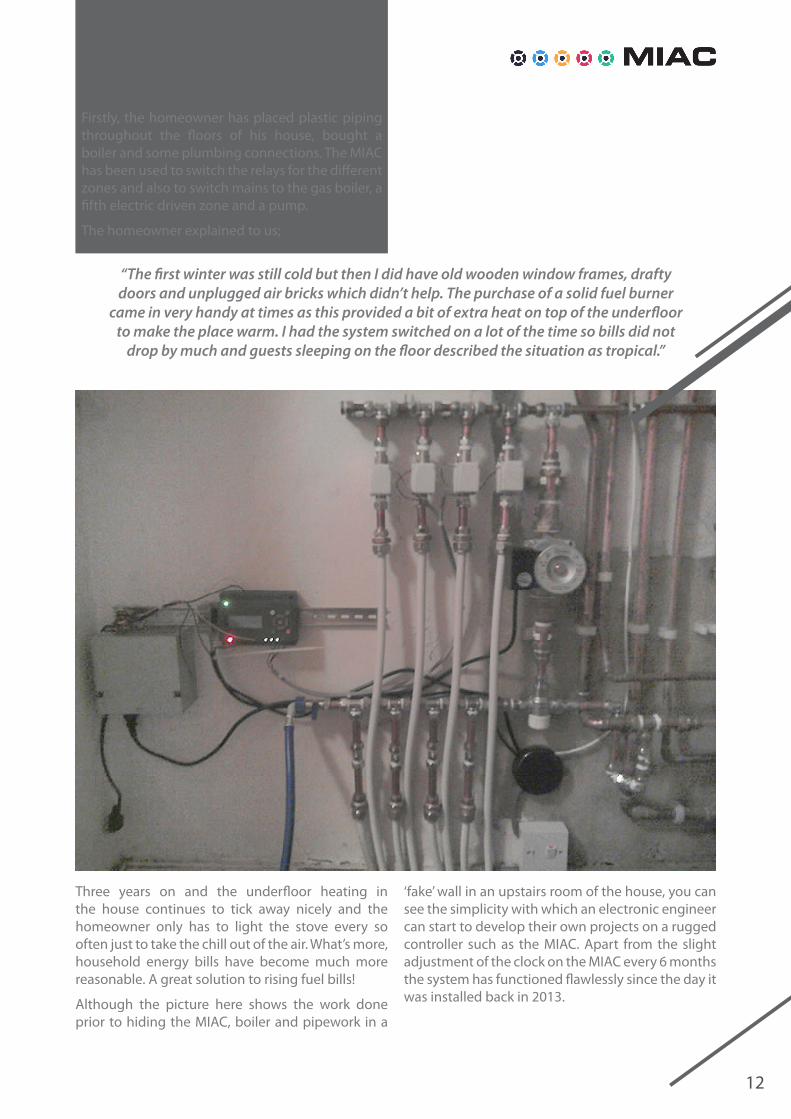
The MIAC has been used to switch the relays for the different zones and also to switch mains to the gas boiler, a fifth electric driven zone and a pump. The MIAC, boiler and pipework are all hidden behind a fake wall in the upstairs of the house; all that remains is a little window which opens to reveal the MIAC display and keypad. All the end user needs to do, is adjust the clock on the MIAC every 6 months or so.
12
Three years on and the underfloor heating in the house continues to tick away nicely and the homeowner only has to light the stove every so often just to take the chill out of the air. What’s more, household energy bills have become much more reasonable. A great solution to rising fuel bills!
Although the picture here shows the work done prior to hiding the MIAC, boiler and pipework in a
Firstly, the homeowner has placed plastic piping throughout the floors of his house, bought a boiler and some plumbing connections. The MIAC has been used to switch the relays for the different zones and also to switch mains to the gas boiler, a fifth electric driven zone and a pump.
The homeowner explained to us;
“The first winter was still cold but then I did have old wooden window frames, drafty doors and unplugged air bricks which didn’t help. The purchase of a solid fuel burner
came in very handy at times as this provided a bit of extra heat on top of the underfloor to make the place warm. I had the system switched on a lot of the time so bills did not
drop by much and guests sleeping on the floor described the situation as tropical.”
‘fake’ wall in an upstairs room of the house, you can see the simplicity with which an electronic engineer can start to develop their own projects on a rugged controller such as the MIAC. Apart from the slight adjustment of the clock on the MIAC every 6 months the system has functioned flawlessly since the day it was installed back in 2013.

13
Using MIAC to Keep us Safe
When choosing a control system for locking an enclosure, you’re spoilt for choice. Matrix’s own E-blocks, or ECIO, or even Raspberry Pi or Arduino extension boards can be used. However, something else that is perfect for this type of job is the MIAC.
The MIAC’s boasts eight digital/analogue inputs, relay outputs, transistor outputs with PWM, a display with control buttons – all neatly encased in a sturdy “top-hat” rail mounting box with screw terminals. It also has protective circuitry to ensure that it keeps on doing its job even if there is a fault in the rest of the system. The hardware in this example is very simple.
There are very few external components; a handful of screw terminals, so that the main installation would need little more than a wire stripper and a screwdriver.

14
A UK based manufacturer recently made a purchase of a CNC machine – aimed at being used mostly for plastic parts and the potential to sculpt 3D shapes from aluminium. Of course, such a machine could also do some rather nasty “3D sculpting” of body parts if there were an accident – and the machine came “out of the box” with no safety features installed and no enclosure of any kind. The requirement for an enclosure of some description, was evident.
The spindle (cutting part of the machine) cannot be controlled either by programming the tool path, nor from the remote control handset. There are no “interlock” switches on the machine. These are commonly fitted to machine tools to ensure that the machine is fully safe before it can be powered; or to prevent locked enclosures from opening while the machine is still active. All of this is quite normal as every machine shop has different needs.
Using the MIAC with a simple hardware system seemed to make perfect sense. The image above shows how the circuit planned out. At the top of
the diagram, you can see the circuitry for the locks. Relay Q1 of the MIAC turns power on and off for both locks – the relays can handle several Amps, so two 0.5 A locks are no trouble. The switch sensors also have relay outputs, the positive power rail is fed via both sensors in series to MIAC input 1 – a 10k resistor connects the input to ground to ensure that there is a very definite “off” condition if either lock fails.
You can read more about this in-depth example through this article online.

15
MIAC Manages Emergency PowerLiving on a rural property just on the outskirts of Sydney, frequently during storms, trees drop branches and transmission lines get damaged. Running a business from an office with no power or communications is not conducive to great customer service!
The solution was to provide an independent source of mains power. A Kubota industrial generator was chosen due to its reliability and affordability. The generator is well rated at 100 A per phase and is driven by a diesel 3.3 L engine, providing power to the office, machine shop, and the house.

16
An automated solution was obviously required; and the MIAC plays an important role. In this project MIAC automates a number of key tasks:
• mains sensing – detects mains failure• engine start sequence• engine management – engine health and fault
management• mains/generator power transfer switch• engine cool down – allowing the engine to cool
down gracefully after being on load
With the added communications features to the new 16-bit dsPIC MIAC, MIAC is now a solid competitor to the traditional industrial based PLCs. I can safely say this as I deal with very large essential power systems on a daily basis – 2 MW above!
Whilst mechanically and electrically sound, the Kubota generator has very limited control systems and has been specifically designed for manual worksite operation. In its off-the-shelf configuration you manually have to turn the ignition key to on, then switch on the glow plugs, then hit start. Once the engine is running, you then have to manually connect to the house mains.
As you can see by the photo above, MIAC was physically mounted on the generator unit, which was done to minimise the volume of remote cabling as MIAC interfaces to numerous points on the generator. The balance of the cabling comes from the mains transfer switch which is located near the main switchboard. Power for MIAC is sourced from the generator battery, which is continually float charged and monitored by the MIAC.
The program was initially created in Flowcode v6 using MIAC V1. Structurally the code was built in 2 main streams supported by 25+ macros and the MIAC component. An interrupted routine was used to monitor mains and engine parameters on a 500ms cycle whilst the tasks were managed in the main program loop driven by data collected from the interrupt cycle. The keypad and display are used to switch between auto and manual with the display providing real-time status information of system performance.

Matrix Technology Solutions Ltd.33 Gibbet Street
HalifaxHX1 5BA
t: +44 (0)1422 252380e: [email protected]
www.matrixtsl.com
MIAC-60-3


