I Case studies of construction dewatering in fine grained Eocene soils by Dr MARTIN PREENE, WJ Engineering Resources Ltd, Chester (formerly Queen Mary & Westfield College, London). a) No pore pressure control Introduction Excavations in fine soil are often unstable when carried out below the natural groundwater level. Stability can be improved by reducing pore water pressures around the excavation. Construction dewatering is a technique for locally reducing pore pressures on a temporary basis by pumping from an array of wells. However, conventional wellpoint and deepwell systems, commonly used for dewatering in coarse soils, are ineffective in fine soils, and vacuum well systems are normally necessary. In this paper, data are presented from several projects involving excavations in low permeability Eocene soils such as the Barton, Bracklesham and Bagshot beds, and methods of estimating steady state flow rate are discussed. Although the particular strata described are only present in the south-east of England, these case studies illustrate several important points which are applicable to fine soils in general. Need for pore pressure control in fine soil In coarse soil, the main aim of construction dewatering is to drain water from the soil pores to prevent flooding of the excavation. In contrast, fine soils cannot be literally 'dewatered', since surface tension forces can retain water in the soil pores and the soil can remain saturated even at large negative pore pressures. The principal mechanism of drainage is consolidation of saturated soil and not replacement of pore water by air. Although the moisture content of the soils will be reduced by only a few percent, control of pore pressures can significantly improve the stability of excavations. This can be illustrated using the theory of effective stress. Effective stress, o', is related to total stress, o, (due to external loads and the self weight of the soil), and the pore pressure, u, by Terzaghi's effective stress equation. a' cr — u Piezometers lf pore pressures are not reduced, effective stress will decrease, reducing the shear strength of the soil and possibly leading to failure b) Pore pressures controlled by vacuum wells Phreatic surface (u =0) Pore pressures can be reduced by pumping from vacuum wells, and effective stress can be controlled. The soil may remain saturated for a considerable depth above the phreatic surface Figure 1:The need for pore pressure controlin hne soil. The shear strength,r, of a soil may be related to effective stress by the Mohr-Coulomb failure criterion r = cr'tandi'2) where tI's the critical state angle of soil friction. If excavation shown in Figure 1 is attempted without any pore pressure control, o will decrease as the overlying soil is excavated and, after the pore pressure reduction due to unloading has dissipated, u will remain approximately constant. Equations (1) and (2) show that effective stress around the excavation will be reduced, and the shear strength of the soil will decrease, making the soil weaker and possibly leading to collapse. However, if pore pressures around the excavation are reduced, effective stress can be controlled and the soil will not be weakened. Fine grained Eocene soils The Eocene soils under consideration consist of three principal strata; Barton beds, Bracklesham beds and Bagshot beds. Figure 2: Outcrops (shown shaded) oMne grained Eocene soilsin south-east England. GROUND ENGINEERING SEPTEMBER 1993
Transcript
I Case studies of construction dewatering in finegrained Eocene soilsby Dr MARTIN PREENE, WJ Engineering ResourcesLtd, Chester (formerly Queen Mary & Westfield
College, London).
a) No pore pressure control
IntroductionExcavations in fine soil are often unstable when carried out below
the natural groundwater level. Stability can be improved by reducing
pore water pressures around the excavation. Construction
dewatering is a technique for locally reducing pore pressures on a
temporary basis by pumping from an array of wells. However,conventional wellpoint and deepwell systems, commonly used for
dewatering in coarse soils, are ineffective in fine soils, and vacuum
well systems are normally necessary. In this paper, data arepresented from several projects involving excavations in low
permeability Eocene soils such as the Barton, Bracklesham and
Bagshot beds, and methods of estimating steady state flow rate arediscussed. Although the particular strata described are only presentin the south-east of England, these case studies illustrate several
important points which are applicable to fine soils in general.
Need for pore pressure control in fine soilIn coarse soil, the main aim of construction dewatering is to drain
water from the soil pores to prevent flooding of the excavation. In
contrast, fine soils cannot be literally 'dewatered', since surface
tension forces can retain water in the soil pores and the soil can
remain saturated even at large negative pore pressures. Theprincipal mechanism of drainage is consolidation of saturated soil and
not replacement of pore water by air. Although the moisture content
of the soils will be reduced by only a few percent, control of porepressures can significantly improve the stability of excavations. This
can be illustrated using the theory of effective stress.Effective stress, o', is related to total stress, o, (due to external
loads and the self weight of the soil), and the pore pressure, u, byTerzaghi's effective stress equation.
a' cr — u
Piezometers
lf pore pressures are not reduced, effective stress willdecrease, reducing the shear strength of the soil and possiblyleading to failure
b) Pore pressures controlled by vacuum wells
Phreaticsurface (u =0)
Pore pressures can be reduced by pumping from vacuum wells,and effective stress can be controlled. The soil may remainsaturated for a considerable depth above the phreatic surface
Figure 1:The need for pore pressure controlin hne soil.
The shear strength,r, of a soil may be related to effective stress by
the Mohr-Coulomb failure criterion
r = cr'tandi'2)where tI's the critical state angle of soil friction. If excavation
shown in Figure 1 is attempted without any pore pressure control,
o will decrease as the overlying soil is excavated and, after the pore
pressure reduction due to unloading has dissipated, u will remain
approximately constant. Equations (1) and (2) show that effective
stress around the excavation will be reduced, and the shear strength
of the soil will decrease, making the soil weaker and possibly leading
to collapse. However, if pore pressures around the excavation are
reduced, effective stress can be controlled and the soil will not be
weakened.
Fine grained Eocene soilsThe Eocene soils under consideration consist of three principal
Type A recharge conditions Water bearing highpermeability stratum
o ~ ...~'...".o.g . Fine grained low~ permeability stratum
, -...,......'......~lmpermeablestratum
Type Brecharge conditions
Fine grained lowpermeability stratum
~ Impermeable stratum
Figure 3:Case studies: Dimensions and ground conditions.
Figure 2 shows the areas of south-east England where these strataoutcrop (British Geological Survey, 1979).These fine soils can varygreatly in nature, in places being an apparently structureless uniform
silty or clayey fine sand, and in other areas being a thinly laminatedsilty fine sand/silty clay. These strata are normally underlain by thevery low permeability London Clay. In several of the case studiesthese soils were overlain by highly permeable River Terracegravels.
Permeability can vary widel~ for these fine Eocene soils, with theoverall range probably 5x10 to1x10 4m/s. Due to limitations in
measurement techniques it can be difficult to obtain accurateestimates of permeability at a given site. Because the performance ofa construction dewatering system is highly dependent on soilpermeability, the designer has a problem when selecting aconstruction dewatering strategy. At the higher end of the possiblepermeability range, conventional wellpoint and deepwell systems will
be viable. At the lower end of the range, no pore pressure controlmeasures will be necessary for temporary excavations that will onlybe open for a few months. However, in the middle of the rangevacuum well systems must be used. Later in this paper, the problemwill be illustrated by comparing back-calculated values of permeabilitywith the data available at the design stage.
Case studiesSeveral published case studies describe construction dewatering in
these soils. Glossop 4 Skempton (1945) and Harding (1946)describe applications of wellpoint and deepwell dewatering, and the
24 problems of low well yields and poor drawdowns which were
GROUND ENGINEERING SEPTEMBER 1993
encountered. McHaffie (1938)and Harding (1938)describe an earlyuse of deepwell dewatering in the Bracklesham beds, for the KingGeorge V graving dock in Southampton. Although constructiondewatering was successful for this project, a 'design as you
go'rocedureseems to have been used, and the required drawdowns ofpore pressure were only achieved over a period of six months. Thisprocedure may not be acceptable on modern 'fast track'onstructionprojects; accurate estimates of dewatering requirements are neededbefore site work begins.
To overcome the poor performance of conventional dewateringsystems, vacuum well systems were developed for use in fine soils.The three main types of these systems are vacuum wellpoints;ejector wells; and deepwells with vacuum. Descriptions of thesesystems can be found in Somerville (1986) and Powers (1991).There are comparatively few published data on these types ofsystem, so data will now be presented from eight case studies.Excavation geometry and ground conditions are given in Figure 3and selected permeability data are summarized in Figure 4.
Calculation of flow rateThe steady state pumped flow rate, q, is an important factor in thedesign of well systems. In this section, estimation of q and selectionof appropriate values of permeability will be discussed. In each casestudy the fine grained stratum was underlain by the effectivelyimpermeable London Clay. Figure 3 indicates which case studieshad type A recharge conditions, where the fine grained stratum wasoverlain by a highly permeable water bearing stratum, and type Bconditions, where the highly permeable stratum was absent.
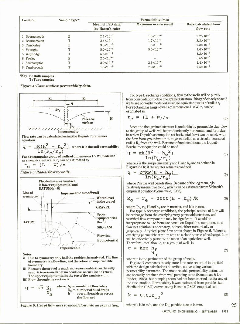
Location
1. Bournemouth
2. Bournemouth
3. Camberley
4. Pirbright
5. Weybridge
6. Fawley
7. Soutbampton
8. Farnborough
Sample type*
BTBTTBTT
Mean of PSD data(by Hazen's rule)
2.1x10 3
2.4x10'.8x10
'.0x105
5.6x10'.0x10s
2.0x10 «
1.5x10
'ermeability (m/s)
Maximum in situ result
1.5x10-'.7x10 4
1.5x10'.0x10«
3.5x10 «
7.0x10
'ack-calculated from
flow rate
3.2x10 5
3.8x10 5
7.8x10 «
1.6x10 5
4.3x10'.6x10
'.4x10
7 5x10
«Key B:Bulk samplesT:Tube samples
Figure 4: Case studies: permeability data.
'r. 'I
2r«'
For type Brecharge conditions, flow to the wells will be purelyfrom consolidation ofthe 6ne grained stratum. Rings of dosely spacedwells are normally modelled as single equivalent wells of radius r,.For rectangular rings of wells of dimensions LxW, r, can beestimated as
Notesi) Due to symmetry only half the problem is analysed. The line
of symmetry is a flowline, and therefore an impermeableboundary.
ii) Because the gravel is much more permeable than the siltysand, it is assumed that no head loss occurs in the gravel.The upper equipotential is the top of the sand stratum.
iii) Flow through the section is
q = kh Nf where: Nf ——number of flowtubesN„= numberofheaddropsh = overall head drop across
the flow net
Figure 6: Use offlo nets to model fiowinto an excavation.
/ ////////// ///'/ // / // ///Impermeable
Flow rate can be calculated using the Dupuit-Forcheimerequation
q = nk(H — hW~ wherekisthesoilpermeability2 2
ln (Ro/re)For a rectangular group ofwells ofdimensions LxW (modelledas an equivalent well), r can be estimated by
re = (L + W)/n
Figure 5:Radialflow to wells.
Since the fine grained stratum is underlain by permeable clay, flow
to the group of wells will be predominantly horizontal, and formulae
based on Dupuit's assumption (of horizontal flow) can be used, with
the Qow from groundwater storage modelled as a circular source atradius R, from the welL For unconfined conditions the Dupuit-
Forcheimer equation could be used
nk (H2 h 2~ln (Ro/re)
where k is the soil permeability and H and h„are as de6ned in
Figure 5 Or, if the aquifer remains confined
q = 2IOsP(H — h,,~ln(Ro/re~
where P is the well penetration. Because of the log term, q isrelatively insensitive to R which can be estimated from Sichardt'sempirical equation (Somerville, 1986)
(4)
(5)
Ro re + 3000(H — hw) (6)
where R„r„Hand h„are in metres, and k is in m/s.For type A recharge conditions, the principal source of flow will
be recharge from the overlying very permeable stratum, and
vertifical flow components may be signi6cant. It would beinappropriate to use formulae based on Dupuit's assumption, so aQow net solution is necessary, solved either numerically orgraphically. A typical plane flow net is shown in Figure 6. Where an
overlying permeable stratum acts as a close source of recharge, flow
will be effectively plane to the faces of an equivalent well.Therefore, total flow, q, to a group of wells is
q = khp Nfh
where p is the perimeter of the group of wells.Figure 7 compares steady state flow rate recorded in the field
with the design calculations described above using variouspermeability estimates. The most reliable permeability estimatesare normally obtained from well pumping tests (Kruseman % DeRidder, 1983), but pumping tests had not been carried out for any ofthe case studies. Permeability k was estimated from particle sizedistribution (PSD) curves using Hazen's (1892) empirical rule
0 (8)
where k is in m/s, and the Dm particle size is in mm.lf
GROUND ENGINEERING SEPTEMBER 1993
Location Pumpingmethod»
Installedcapacity
(Vs)
Field recordsdrawdown flow rate
(Vs)
Design flow ratesfrom mean from max
PSD0 in situ(Vs) (Vs)
1.Bournemouth2. Bournemouth
3. Camberley
4. Pirbright
5. Weybridge6. Fawley7. Southampton
8. Farnborough
505050
750
1.42318
4.42.54.09.56.02.56.02.23.8
2.57.00.42.02.04.00.30.37.7
90(B)47(T)2.4(B)8.1(B)4.9(T)4.7(T)1.1(B)
0.01(T)15(T)
0.2321.03.20.8
0.572
Key VWP: Vacuum wellpointsEJ:Ejector wells(B):Permeability taken from bulk samples(T):Permeability taken from tube samples
Figure 7:Case studies: design, installed and recorded flow rates.
However, equation (8) and other methods of estimatingpermeability from PSD tests (eg Somerville, 1986p16) weredeveloped for relatively uniform sands, with negligible silt or claycontent, and their application to these soils, many of which havecombined silt and clay contents of 10 to 20%, is questionable. Also,PSD tests in structured soils (eg with discrete finer/coarser layers)may tend to mis-estimate the mass soil permeability due to themixing of soil layers during sampling. It can be seen from Figure 7that flow rates calculated using the mean permeability from PSDresults of bulk samples tend to be over-estimates, but that the meanof tube samples (U100 and SPT) tends to give better estimates.This is consistent with loss of fines from bulk samples recoveredfrom water 6lled boreholes. It may be possible to obtain betterpermeability estimates from bulk samples by using a permeabilitybetween the mean and the minimum results. However, this methodis unlikely to yield precise results, as the degree of loss of 6nes mayvary from sample to sample.
Figure 7 also shows the results of flow rate calculations based onpermeability from in situ constant and variable head tests in
boreholes and piezometers. There are several factors, such as soildisturbance caused during drilling, which mean that the results of insitu tests tend to underestimate the true permeability, andtherefore, in calculations the maximum result was used instead ofthe mean. Of the six cases where in situ tests were available, in 6vecases the maximum permeability gave better estimates than fromthe mean of PSD results. This highlights the limitations of PSDresults in 6ne soils. The methods described in this section wereused to back-calculate mean values of permeability from therecorded flow rates; Figure 4 compares these results with the dataavailable at the design stage. For all the case studies, PSD resultssigni6cantly over-estimated the permeability of these soils, by up totwo orders of magnitude. No such clear trend is apparent from the in
situ test results, but in general they are better estimates ofpermeability. The overall range of back-calculated permeability is4 x 10 'o 1x 10 sm/s. Further discussion of the selection ofpermeability is given in Preene 8z Powrie (1993).
Effect ofaquifer boundary conditionsWhen steady state flow rate is calculated, it is generally recognisedthat an accurate permeability estimate is necessary for design.However, in 6ne soils, flow rate is also significantly affected by aquiferboundary conditions, in particular close sources of recharge. Figure8 shows a section through case study 2, where the silty sands of theBracklesham beds (k = 5x 10 m/s) are overlain by highly permeablegravels (k= 10 m/s), with a thin layer of clay at the sand/gravelinterface. This section was based on the logs of relatively widelyspaced boreholes, and a key question is whether the thin clay layer iscontinuous and impermeable, and hydraulically separates the sandand gravel, Figure 8(a); or whether the sand and gravel are in
hydraulic connexion, Figure 8(b). For the first case, analysed with
GROUND ENGINEERING SEPTEMBER 1993
a) Section through excavation: gravel and silty sand separatedby impermeable clay layer
of WeIIPoints 0246msymmetry
.:o,, SandyGRAVEL,;Initial:", Silty CLAY -
'
? .-.
Typical flowlines
All flow is from groundwater storage in the silty sand (modelledas a distant circular source)
b) Section through excavation: gravel and silty sand inhydraulic connexion
0246m
o '„:'Sandy GRAVEL> I,",—;"! Initial
nes
Flow is from recharge from overlying permeable gravel andfrom storage in the silty sand
Figure 8:Effect ofrecharge conditions.
[ Dupuit based equations and using appropriate values of permeability,flow rate q is approximately 5 litre/s. For the second case, analysedby flow nets, q is an order of magnitude greater at approxilnately 47litre/s. This illustrates that, for the relatively common case of a finesoil adjacent to a waterbearing highly permeable soil, apparentlyinsignificant geological features can have a large effect on flow rates.In reality, the recorded flow rate was7 litre/s, indicating actual recharge conditions were between the twocases shown.
ConclusionsData have been presented from several studies of vacuum well
systems operating to control pore pressures in fine grained Eocenesoils such as the Barton, Bracklesham and Bagshot beds. It wasshown that PSD tests overestimated permeability by up to twoorders of magnitude compared to values back-calculated from therecorded flow rate. In general, the maximum in situ test result was abetter estimate. For the case studies, permeability values back-calculated from the performance of the construction dewateringsystems were in the range 4x10 to 1x10 em/s. A case studywas used to illustrate that close sources of recharge can increaseflow rate by an order of magnitude. The Eocene soils consideredhere may be overlain by permeable gravels; the recharge from thegravels may be affected by minor geological features which must becarefully assessed in design.
AcknowledgementsWhen this work was carried out the author was employed on aScience and Engineering Research Council contract. Site facilitiesand data were provided by WJ Engineering Resources Ltd ofBushey, Hertfordshire.
ReferencesBritish Geological Survey, (1979).Geological map of the United Kingdom south. 3rd Edsolid.R Glossop & AW Skempton (1945). 'Particle-size in silts and sands'. Journ. ICE, Vol 25,pp81-105.IUB Harding (1938). 'Correspondence on Southampton docks extension'. Journ. ICE,Vol 9, pp562-4.HJB Harding (1946). 'The choice of expedients in civil engineering construction'. WorksConstruction Division, ICE, Paper No 6, pp3-31.A Hazen (1892). 'Physical properties of sands and gravels with reference to their use ingltration'. Report to the Massachusetts State Board of Health, p539.GP Kruseman & NA De Ridder (1983). 'Analysis and evaluation of pumping test data'.3rd Ed. International Institute for Land Reclamation Improvement, Wageningen, TheNetherlands.MGJ McHaffie (1938). 'Southampton docks extension'. Journ. ICE, Vol 9, pp184-219.JP Powers (1991).'Construction dewatering: new methods and applications'. 2ndedition, Wiley, New York.M Preene & W Powrie (1993). 'Steady-state performance of construction dewateringsystems in fine soils'. Georrchriique, Vol 43, No2, pp191-205.SH Somerville (1986). 'Control of groundwater for temporary works'. ConstructionIndustry Research & Information Association, Report 113, London.
VAN ELLE {HOLDINGS}0 NIINI PILING ~ UNDERPINNING~ PILING ~ DRILLING AND GROUTING~ GROUND ANCHORS~ CIVIL & BUILDING WORKS