Rudy, M. (2006). “Case Study Guide.” archistructura – study aids, web publication, Vienna University of Technology: Institute of Architectural Sciences, http://www.archistructura.net/study/index_en.htm.
Building Science: Advanced Structures Institut für Architekturwissenschaften: Tragwerksplanung und Ingenieurholzbau CASE STUDIES IN STRUCTURAL DESIGN CS AIMS & SCOPE OF CASE STUDIES ......................................................... 1 Objectives ............................................................................................ 2 Project Scope ....................................................................................... 3 Introduction to Semantic Profiles ............................................................. 5 1. RULES & STANDARDS FOR CASE STUDIES ............................................. 7 Folder Structure & File Names ................................................................. 7 File Formats .......................................................................................... 10 1.1. Citing Literature & Other Sources ............................................................ 11 Citing a Reference Source ...................................................................... 11 Documenting References in an Index ....................................................... 13 1.2 Terminology of Classification .................................................................. 15 General Syntax Guidelines ...................................................................... 15 Classification Systems as Online Study Aids ............................................. 16 2. WORKING GUIDE & INSTRUCTIONS ........................................................ 19 General Handling of Text in Workbooks .................................................... 19 Integrating Graphic Information ............................................................... 20 2.1 Recommendations for the Research Phase ................................................ 23 Reference Index of Sources .................................................................... 24 Image Index of Figures ........................................................................... 26 2.2 Content & Working Methods for the Analysis Phase .................................. 27 Analysis Workbook ................................................................................ 29 CAD Model Renderings .......................................................................... 30 2.2.1 Analytically Modelling the Overall System.................................................. 33 3D Model of the Load-bearing Structure ................................................... 33 3D Model of the Thermal Envelope .......................................................... 35 2.2.2 Analytically Modelling the Construction .................................................... 39 3D Model of a Construction Detail ........................................................... 39 Reference Systems for Construction Vocabulary ........................................ 42 2.3 Documenting the Case Study in a Complete Report .................................... 57 Table of Contents .................................................................................. 57 Case Study Editing Process .................................................................... 58 2.3.1 Basic Building & Case Study Information .................................................. 59 Polarity Profile for the Building ................................................................ 61 2.3.2 Outlining & Formulating the Report in Chapters ......................................... 63 On Using Style Sheets ........................................................................... 64 References to Sources and Figures .......................................................... 66 2.4 Summarising the Case Study in an Abstract .............................................. 69 > Case Study Submission Checklist ............................................................ 71 > References ........................................................................................... 73
CS AIMS & SCOPE OF CASE STUDIES ......................................................... 1 Objectives ............................................................................................ 2 Project Scope ....................................................................................... 3 Introduction to Semantic Profiles ............................................................. 5
1. RULES & STANDARDS FOR CASE STUDIES ............................................. 7 Folder Structure & File Names ................................................................. 7 File Formats .......................................................................................... 10
1.1. Citing Literature & Other Sources ............................................................ 11 Citing a Reference Source ...................................................................... 11 Documenting References in an Index ....................................................... 13
1.2 Terminology of Classification .................................................................. 15 General Syntax Guidelines ...................................................................... 15 Classification Systems as Online Study Aids ............................................. 16
2. WORKING GUIDE & INSTRUCTIONS ........................................................ 19 General Handling of Text in Workbooks .................................................... 19 Integrating Graphic Information ............................................................... 20
2.1 Recommendations for the Research Phase ................................................ 23 Reference Index of Sources .................................................................... 24 Image Index of Figures ........................................................................... 26
2.2 Content & Working Methods for the Analysis Phase .................................. 27 Analysis Workbook ................................................................................ 29 CAD Model Renderings .......................................................................... 30
2.2.1 Analytically Modelling the Overall System.................................................. 33 3D Model of the Load-bearing Structure ................................................... 33 3D Model of the Thermal Envelope .......................................................... 35
2.2.2 Analytically Modelling the Construction .................................................... 39 3D Model of a Construction Detail ........................................................... 39 Reference Systems for Construction Vocabulary ........................................ 42
2.3 Documenting the Case Study in a Complete Report .................................... 57 Table of Contents .................................................................................. 57 Case Study Editing Process .................................................................... 58
2.3.1 Basic Building & Case Study Information .................................................. 59 Polarity Profile for the Building ................................................................ 61
2.3.2 Outlining & Formulating the Report in Chapters ......................................... 63 On Using Style Sheets ........................................................................... 64 References to Sources and Figures .......................................................... 66
2.4 Summarising the Case Study in an Abstract .............................................. 69
> Case Study Submission Checklist ............................................................ 71
"We are not analysing works that we would like to copy or that we mistrust. We shall investigate the paths taken by others in creating their work, because knowing such paths gets us moving ourselves." Freely translated from the German words of Paul Klee (Nov. 14, 1921).
[Spiller 1990]
At the heart of a case study lies the systematic analysis of an existing building structure to reveal design-relevant relation-ships between space, force, energy, and construction methods. Case study content is developed during the course of the semester (lectures and workshops) in 3 main stages:
1. Research 2. Analysis 3. Report
> Guide
00_scheme_01
Work phases of a case study.
The case studies submitted at the end of the term will be published online by the Department of Structural Design and Timber Engineering, both to document course results as well as to enhance the valuable building information resources provided to the general public in the framework of archistruc-tura (see links right and next sections).
The professions of architecture and civil engineering are often considered together as a generalised building design and con-struction discipline ("AEC") that ideally works as one to opti-mally design our built environment. There are, however, obvi-ous and fundamental differences in the respective working methods of each profession, which are reflected in mutually distinct styles of academic training. Especially the differing approaches to rendering and communicating design concerns impede interdisciplinary cooperation in both training and prac-tice.
Although technical universities such as the Vienna University of Technology offer both architecture and engineering pro-grammes, these generally remain separate faculties with dis-tinct teaching and learning styles that reflect the dichotomy between the practicing professions. Building science is a pri-marily academic discipline that is closely related to (but not identical with) the professional disciplines of architecture and civil engineering. As such, it can be seen as a potential bridge between the two professions in education.
MSc programme: building science & technology
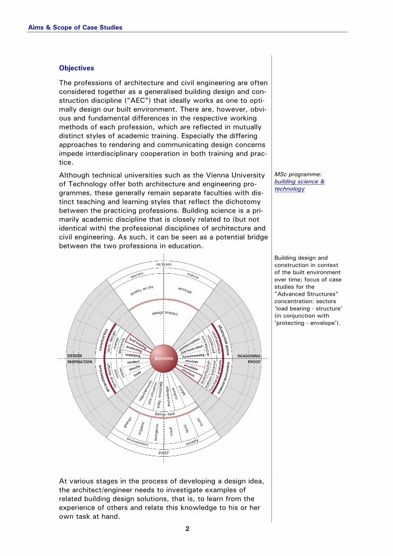
00_scheme_00
Building design and construction in context of the built environment over time; focus of case studies for the "Advanced Structures" concentration: sectors 'load bearing - structure' (in conjunction with 'protecting - envelope').
At various stages in the process of developing a design idea, the architect/engineer needs to investigate examples of related building design solutions, that is, to learn from the experience of others and relate this knowledge to his or her own task at hand.
Though such case-based reasoning is central to developing design skills and refining technical design solutions, the con-ceptual decision to take a particular case as a precedent in the first place must be based on a judgment of the building as a whole, that is, as a complete solution to a complex design problem. With this in mind, an analytically structured and profiled col-lection of case studies forms the core of both student coursework and the "knowledge construction site" that is archistructura.
> Semantic Profiles
Project Scope scope
The building cases to be studied each term are selected based on the accessibility of information to participating stu-dents, taking into account the focus and teaching objectives of the current course offerings. The complete study of a sin-gle building structure is required of each student to earn full credit for a case-based, seminar-style course (e.g., "Advanced Structural Systems and Construction Methods" in the building science programme or equivalent seminars in the architecture curriculum). Note: Collaboration on such studies is encouraged, in which case two declared co-authors are expected to jointly cover 2 building structures.
building collection: student resources > ‘advanced structures: case study objects’
In order to enable publication in the archistructura framework, each case study must be submitted as a digital information package that formally adheres to strict specifications (see also "Rules & Standards") and includes the following main components:
> Rules & Standards
analysis workbook for documenting the CAD-based
analytical modelling work (contents of system and construction models, with rendering index);
system model(s) of the load-bearing structure and, if applicable, the thermal envelope (3D CAD, abstracted in terms of simulation analysis parameters);
construction model(s) of 1-2 key technical details of the building (e.g., 1 complex detail where structure and envelope join or 2 strictly structural details for buildings without a significant envelope);
report workbook containing general information (building, author and status) and tables of contents, figures, and sources (key indices);
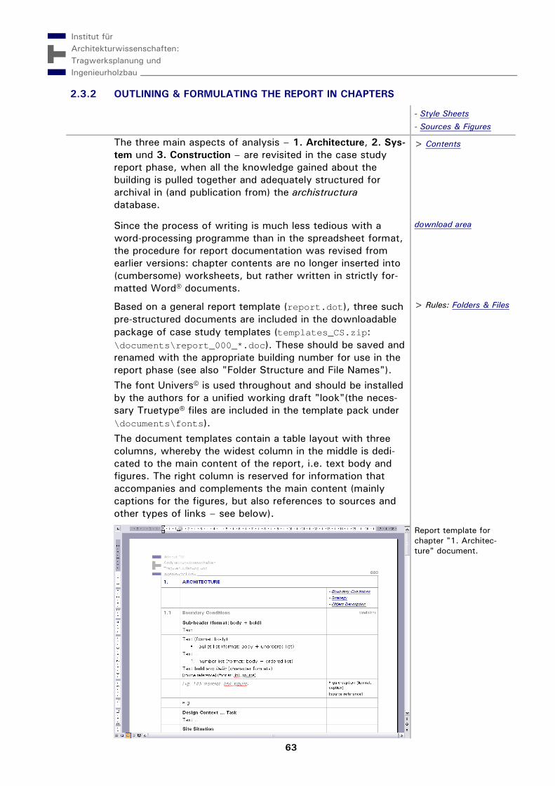
report documents explaining the results of the case study work in publishable form (structured in accordance with the overall analysis scheme and systematically linked to the key indices of the report workbook);
photos, drawings, model renderings, and other data files that are referenced in the workbooks (indexed renderings and figures);
abstract that briefly summarises the key characteristics of the analysed building (1 A4 page, including graphics).
The results of simulation analysis work done concurrently for credit in the course "IT-based Structural Design Methods" should also be reflected in the final report.
Simulation Analysis (guide soon to be published)
00_modell_456
Analysing the load-bearing behaviour of a building by simulating the deformation of a structural model.
Technical information can only serve to inform the building design process effectively if communicated on the basis of comparisons that allow the architect to relate them qualita-tively. In other words, case-based detail knowledge must be tied to the kinds of polarities that enable an interpretive com-parison of competing options, such as "better/worse," "effi-cient/inefficient," "light/heavy," and so on.
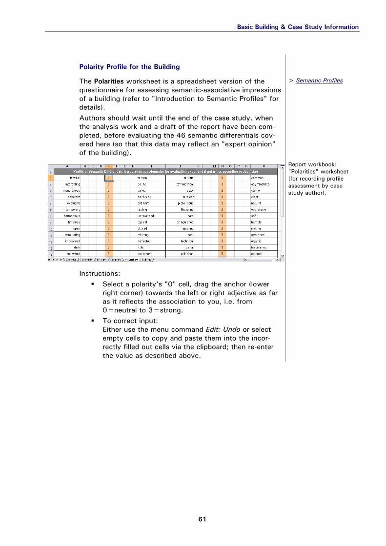
So-called polarity profiles describe a set of characteristics by a method of semantic differentials, whereby the tendential qualities of a building are reviewed in the span between semantically opposing terms. At present, our building collec-tion tracks such profiles to describe architectural "Gestalt-wirkung" (perceived form, expression, and quality) based on an originally German assessment covering 46 antonym pairs.
[Joedicke 1977]
Correlative comparisons of different buildings with similar polarity profiles and recurring morphological features can reveal relationships between architectural characteristics and associative impressions that reflect generally applicable aes-thetic principles. At present, two types of – semantically aligned – composite renderings of averaged profile data are available in archistruc-tura to facilitate basic forms of correlation analysis (multidi-mensional composite views for cross-dimensional analysis are currently in development).
00_profile_form
Questionnaire for assessing the polarity profile (> 'form').
Aims & Scope of Case Studies
6
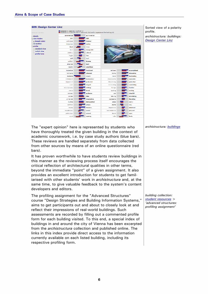
00_profile2_609
Sorted view of a polarity profile.
archistructura: buildings: Design Center Linz
The "expert opinion" here is represented by students who have thoroughly treated the given building in the context of academic coursework, i.e. by case study authors (blue bars). These reviews are handled separately from data collected from other sources by means of an online questionnaire (red bars). It has proven worthwhile to have students review buildings in this manner as the reviewing process itself encourages the critical reflection of architectural qualities in other terms, beyond the immediate "point" of a given assignment. It also provides an excellent introduction for students to get famil-iarised with other students' work in archistructura and, at the same time, to give valuable feedback to the system's content developers and editors.
archistructura: buildings
The profiling assignment for the "Advanced Structures" course "Design Strategies and Building Information Systems," aims to get participants out and about to closely look at and reflect their impressions of real-world buildings. Such assessments are recorded by filling out a commented profile form for each building visited. To this end, a special index of buildings in and around the city of Vienna has been excerpted from the archistructura collection and published online. The links in this index provide direct access to the information currently available on each listed building, including its respective profiling form.
building collection: student resources > ‘advanced structures: profiling assignment’
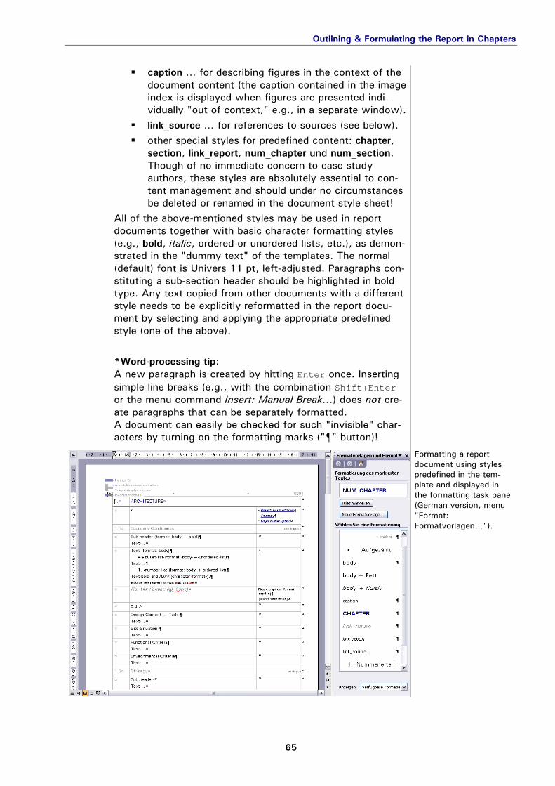
The initiative behind archistructura seeks to promote the sustainability of quality information by engaging students directly in the development of content that is worthy of pub-lication in an online building collection. Beyond what is actu-ally published in HTML for the general public at any given time, a range of additional resources (such as archive data, simulation models, prototypes of calculation tools and other design support modules) are maintained and developed within the "live" archistructura database of the department. Integrating such highly facetted data in a rapidly growing system demands a considerable amount of processing disci-pline on the part of the students involved. Only strict adher-ence to the "regulations" spelled out in this section ensures that the information created and developed for the building collection can be consistently maintained and made available to others, be it in published form or as foundation data for succeeding case studies (e.g., simulation analysis courses or study trips).
[ITI 2005]
In order to decentralise content development without loss of "knowledge" (structured information), a flexible case study workflow has been established with an eye on the general availability and interoperability of standard software applica-tions.
The phases of the case study process are documented in accompanying sets of "worksheets" ("workbooks") and documents, which are pre-formatted in a standard office application suite (MS Office®). A general workbook, set up for the assigned building, is provided to the authors at the beginning of the semester; accompanying files (for analysis and report documentation) are accessible in the download area of the department website (templates_CS.zip) At the end of the semester, students submit all the informa-tion created and processed in the course of the case study in digital media form (CD-R recommended), with paper print-outs of the worksheet contents. After proof reading and assessment by the instructors, the digital workbooks are exported as XML data for incorporation in the archistructura database.
download area
Folder Structure & File Names files
The submitted digital information package mentioned in the section "Project Scope" should be organised by case study in a folder labelled with the object number and last name of the author, i.e. ###_Name, whereby "###" stands for the 3-digit object number that is assigned to the building in archis-tructura. Co-authors extend the folder label to include the
additional name(s) separated by an underline, i.e. ###_Name1_Name2. The workbooks (Excel®), report and abstract documents (Word®) are saved with the appropriate object number appended to the standard file name (e.g., analysis_123.xls, report_123.xls, report_123_1.doc, report_123_2.doc, report_123_3.doc, and asbract_123.doc). All in all, the primary file and folder structure of each case study should appear as follows:
01_filefolders
Folder structure and key files of a case study.
The folder \CAD\ is where the 3D-CAD files from the analyti-cal modelling work should be found (e.g., AutoCAD® file lable.dwg). The subfolder \2d\ is for collecting the image files produced to document the models in renderings (more on the analysis workbook and rendering contents in "Work-ing Guide: Analysis").
> Guide: Analysis
The folder \images\ contains all graphic and other files used as figures in the final report in their original format (see also next section and „Working Guide: Report"). Aside from the format (reflected in the extension ".*"), these files should be named in a standardised fashion that eases content identifi-cation for better post-processing. The full file name consists of a class name followed by an underline and a 2-digit running number: class_##.* (for example, plan_det_01.dwg or photo_12.tif; see also "Important Note" below).
> Guide: Report
01_filenames
Recommended class labels for naming data files used as figures in the report ("##"=number in series).
Rules & Standards for Case Studies
9
To avoid producing unnecessarily unwieldy abstract docu-ments at the end of the semester, any especially large im-ages used in the single-page summary should be reduced in size before insertion into the Word® template. Such reduced versions of image files are saved to the \abstract\ sub-folder with a "-" sign appended to the name (class_##-.*).
> Guide: Abstract
Important Note:
Though these file naming rules formally apply only to the case study package as submitted, students should be aware of them from the beginning of their work.
It is strongly recommended that authors already use the specified file management conventions to identify and prop-erly classify data as they are collected and structured during the initial research phase. Experience has shown that, aside from improving the overall quality of the finished product, this saves a lot of time and aggravation shortly before the case study due date!
> Guide: Research
Rules & Standards for Case Studies
10
File Formats formats
The various components of a complete case study package may be submitted in file formats that are prescribed or rec-ommended depending on data type.
01_fileformats
Format options specified for different types of file content.
A companion goal of case study coursework is to train gen-eral skills in scientific methods. The basic principles behind such methods, which are applicable to all fields of academic and scientific research work, essentially revolve around
structured thinking … organising complex empirical information in theoretical frameworks; discovering and understanding interdependencies and relationships; creating and communicating new understanding of the world.
systematic processing … clearly formulating the objectives and questions of investigation; researching and developing the information needed to find meaningful answers; following through to methodically interpret results and draw focussed conclusions.
applying the "academic craft" … gaining awareness of and learning from existing sources of knowledge; contributing to the expansion, extension, and improvement of knowledge resources available to everyone ("what goes around, comes around").
Concretely, the last point means that: information sources are correctly cited ("give credit
where credit is due") and results are documented in clear writing so as to be
readable – and comprehensible – to others. The next sections provide only a brief summary of conven-tions for citing sources correctly in academic writing. The basic rule is that the author's knowledge base for a given investigation, i.e. every source of information specifically relevant to the object of study, is documented in a reference (appended index or footnotes) and cited where appropriate in the body of text and figures conveyed to potential readers.
Citing a Reference Source citation
In shorter works (papers or articles less than 10 pages), where it is not too great an inconvenience for the reader to flip back and forth between text body and reference informa-tion, the sources may be referred to with running numbers, e.g.:
... blabla as described in [1] blabla ... The full reference information is then listed at the end of the paper as "credits in order of appearance" with the respective reference numbers. As a service to the reader of more involved written works
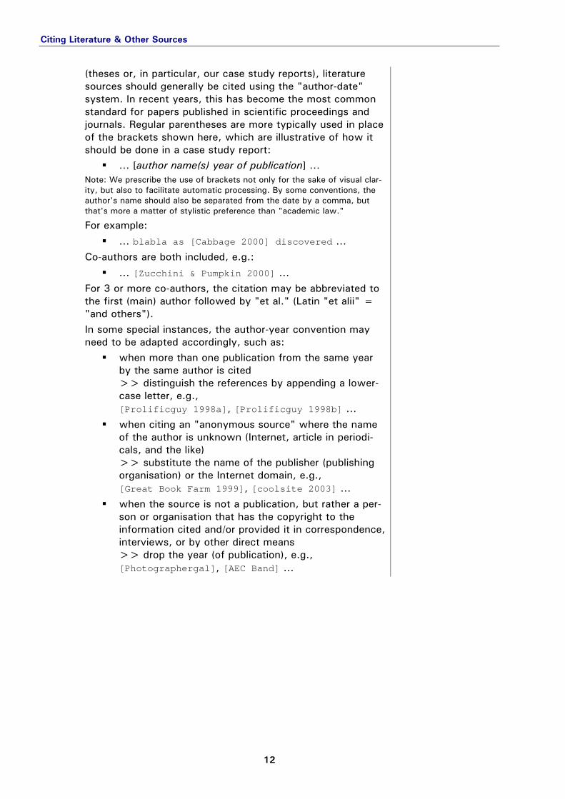
(theses or, in particular, our case study reports), literature sources should generally be cited using the "author-date" system. In recent years, this has become the most common standard for papers published in scientific proceedings and journals. Regular parentheses are more typically used in place of the brackets shown here, which are illustrative of how it should be done in a case study report:
... [author name(s) year of publication] ... Note: We prescribe the use of brackets not only for the sake of visual clar-ity, but also to facilitate automatic processing. By some conventions, the author's name should also be separated from the date by a comma, but that's more a matter of stylistic preference than "academic law."
For example: ... blabla as [Cabbage 2000] discovered ...
Co-authors are both included, e.g.: ... [Zucchini & Pumpkin 2000] ...
For 3 or more co-authors, the citation may be abbreviated to the first (main) author followed by "et al." (Latin "et alii" = "and others"). In some special instances, the author-year convention may need to be adapted accordingly, such as:
when more than one publication from the same year by the same author is cited >> distinguish the references by appending a lower-case letter, e.g., [Prolificguy 1998a], [Prolificguy 1998b] ...
when citing an "anonymous source" where the name of the author is unknown (Internet, article in periodi-cals, and the like) >> substitute the name of the publisher (publishing organisation) or the Internet domain, e.g., [Great Book Farm 1999], [coolsite 2003] ...
when the source is not a publication, but rather a per-son or organisation that has the copyright to the information cited and/or provided it in correspondence, interviews, or by other direct means >> drop the year (of publication), e.g., [Photographergal], [AEC Band] ...
Citing Literature & Other Sources
13
Documenting References in an Index sources
Sources are indexed in alphanumeric order by the reference name used in the citation as described above. The "author-date" system has advantages for both writer and reader, since it is much easier to maintain and look things up in an alphabetical list of named sources than it is to cross-check reference numbers between citation and reference index every step of the way. The full reference starts after the "author-date" code with more complete information about the author(s) or author sub-stitute (see above). Typical syntax options are as follows:
last name, first name(s) or initial(s), e.g., Shmoe, J. or Traditionalguy, K.H.
up to 3 authors should be always credited, e.g., Prolificguy, A., Realworkgal, B., and Alongfortheride, C.
optionally, but only if there are clearly more than 3 sig-nificant authors, the reference can be shortened to name only the first author (as cited), followed by "et al." for the rest, e.g., Headhoncho, A., et al.
the chief editor (if there is one) should be denoted with an "(Ed.)" after his or her name, e.g., Author, X., Author, Y., & Headhoncho, A. (Ed.)
The rest of the information contained in the reference depends on the type of source ...
book: author(s) (year) book title, edition (if applicable). city: publisher. abbreviated alternative: author(s) (year). book title. ISBN ###. e.g., Lechner, N. (1991) Heating, Cooling, Lighting: Design Methods for Architects. New York: John Wiley & Sons.
chapter/section of a book: author(s) (year) book title, chapter #. ... , pages*. alternative: chapter author(s) (year) “chapter title.” In book title (editor). ... , pages*. e.g., Ridley, L. (1990) "Site, Community, and Urban Planning." In Solar Building Architecture (Anderson, B. Ed.). Cambridge, Massachusetts: The MIT Press, 36-76.
Citing Literature & Other Sources
14
papers in conference proceedings:
author(s) (year) "paper title." Proceedings: conference title. city: publishing organisation, pages*. e.g., Krec, K. and Rudy, M. (1996) "Thermal Building Simulation for Design Practice." Proceedings: International Symposium of CIB W 67, Energy and Mass Flow in the Life Cycle of Buildings. Vienna: CIB, 519-525.
periodicals: author(s) (year) "article title." journal title. volume number, pages*. e.g. Zappa, F. (1968) "Hit Me." SMart Mag 7/1968, 1-2.
* Note on page references: The page range included here is for the entire "reference unit" in a larger body, such as a book or journal. A detail reference to a particular page is usually included in the citation rather than the reference itself. For example, information quoted from page 103 of the reference Name 2000 would appear as "... [Name 2000, 103] ..." in the body. For data-processing rea-sons, such detailed page references are left out of our case reports.
See also "Working Guide: Research: Sources" for more infor-mation on the handling of references in the report workbook.
The practice of scientific working methods aims at creating knowledge that is not only of high quality, but also of high sus-tainability and persistence. This can only be achieved if the information assets that the knowledge is derived from are con-sistently classified and stored in a manner that maintains their accessibility and usefulness for as long as possible. Well-organ-ised libraries are a classic example of this tried-and-true "sus-tainable knowledge management" principle: imagine trying to find a book in a library without a methodical classification sys-tem, without a card catalogue or any other form of searchable index, without even shelves! All of the books stored willy-nilly in such a library could just as well be destroyed, no one would miss them. As mundane a chore as it sometimes is, the importance of clas-sifying things in order to organise them and thus maintain their value cannot be stressed enough – especially where the "thing" is the basis for knowledge. With this in mind, a few useful basics of taxonomic classifications, i.e. giving the "things" names and organising them hierarchically, are covered in the next sections.
General Syntax Guidelines syntax
In every language, there are a number of alternative words for naming such words as are used to name things, for example in English: "name," "label," "key word," "description" … When referring to such designating words here, we use the term "term." A set of terms for things that belong together in some meaning-ful way (e.g., describing the characteristics of another thing, or object) is often called "meta-data" for the object of classifica-tion. The terms and their logical interrelationships, that is, the meta-data structure of the object can be visualised as a mathe-matical expression of the set with logical functions, as a graph of vertices logically related to each other with edges, or as a grammatically ordered and punctuated sequence of vocabulary. The common rules for spelling out the last of these visualisation methods are referred to as "syntax." Since this is the method of choice for documenting meta-data for text-based databases (another way of looking at our case study workbooks), some syntax basics for one particularly useful convention are summa-rised in this section. Multiple terms that have no particular interrelationship (aside from their relevance to the classified object) are written as a string separated with semicolons (";"): term 1; term 2; etc. (e.g., a text string in the field "characteristics" might read:
blue eyes; brunette; medium stature) For thematic fields that can be meaningfully classified based on a tree of hierarchically related terms (as, for example the subject of "basic load-bearing systems"), the levels of classification are strung together in a series of terms separated by colons (":") to establish the hierarchical sequence of their meaning from "gen-eral" to "detailed" classes: class 1 term: class 2 term: etc. (e.g., humankind: relative: first degree: brother) Such a chain of terms can be thought of as a single "path" through a particular tree, also referred to as "taxonomy." A chain constitutes a unit of meta-data, so multiple chains are treated just as multiple simple terms (the shortest possible chain) and separated by semicolons: class 1 term A: class 2 term: etc.; class 1 term B: class 2 term: etc.
If multiple logical chains are applied that distinguish themselves only in the last term (the terms of all higher level classes are identical), the classification can be "consolidated" in a single chain that contains multiple terms at the end separated by com-mas (","). In other words, the multiple units class 1 term A: class 2 term B; class 1 term A: class 2 term C; etc. are consolidated in one meta-data unit: class 1 term A: class 2 term B, class 2 term C, etc. (e.g., relatives: first degree: brother, sister, ...)
Classification Systems as Online Study Aids study_aids
With respect to case study work, the identification of typological elements in the building models during the analysis phase is aided by the use of visual glossaries of terms – so-called "pic-tionaries" – that are accessible directly online. The pictionary application is based on the same hierarchically structured and continually refined taxonomies used to organise the content of other applications in the archistructura system (which is being developed in two language versions concurrently, German and English). Upon opening one of the available pictionaries, the classification tree appears in the left frame, where the terminology can be navigated analogously to a typical file folder browser. Tree branches are opened by clicking on the "+" sign next to a term with sub-branches (and closed again by clicking the "-" sign). Clicking directly on a term fills the content frame to the right with a pictionary page to this term. The key information con-tained in this page is the chain of terms at the top, which denotes the current term's path location in the tree, spelled out as a text string with hierarchical syntax (followed by a transla-tion in German or English below, depending on the target lan-guage of the user interface).
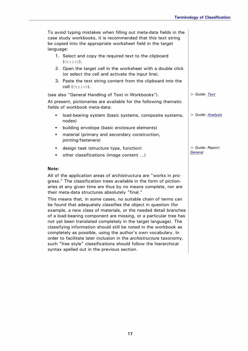
To avoid typing mistakes when filling out meta-data fields in the case study workbooks, it is recommended that this text string be copied into the appropriate worksheet field in the target language:
1. Select and copy the required text to the clipboard (Ctrl+C).
2. Open the target cell in the worksheet with a double click (or select the cell and activate the input line).
3. Paste the text string content from the clipboard into the cell (Ctrl+V).
(see also "General Handling of Text in Workbooks"). At present, pictionaries are available for the following thematic fields of workbook meta-data:
> Guide: Text
load-bearing system (basic systems, composite systems,
nodes) building envelope (basic enclosure elements) material (primary and secondary construction,
jointing/fasteners)
> Guide: Analysis
design task (structure type, function) other classifications (image content …)
> Guide: Report: General
Note:
All of the application areas of archistructura are "works in pro-gress." The classification trees available in the form of piction-aries at any given time are thus by no means complete, nor are their meta-data structures absolutely "final." This means that, in some cases, no suitable chain of terms can be found that adequately classifies the object in question (for example, a new class of materials, or the needed detail branches of a load-bearing component are missing, or a particular tree has not yet been translated completely in the target language). The classifying information should still be noted in the workbook as completely as possible, using the author's own vocabulary. In order to facilitate later inclusion in the archistructura taxonomy, such "free style" classifications should follow the hierarchical syntax spelled out in the previous section.
As related in the previous chapter ("Rules & Standards"), the process of structuring and documenting case study informa-tion centres on "workbook" applications in a standard spreadsheet format. In essence, Excel® is used as a relatively convenient "external database client" for the archistructura system. This allows students to perform the work of prepar-ing their case studies independently, without having to install additional software or access the central database server directly.
> Rules & Standards
Together with summaries of the most important facets of case studies in project phases, this guide provides a few hints and recommendations for working with Excel® more effec-tively (and, perhaps, with less aggravation).
> Case Studies > Research > Analysis > Report
General Handling of Text in Workbooks text
The worksheets are pre-formatted for reasonable printability in A4 landscape format. Cells that should not be changed (headers and the like) are filled grey. Text should only be entered in the unfilled (white) cells, either by typing it in directly or by copying and pasting it from other applications via the clipboard (e.g., word-processing or HTML documents). Before pasting a text string from the clipboard (Ctrl+V), make sure that the cursor is blinking in input mode either directly in the activated target cell or in the input line with the target cell selected. To get the cursor into the right position and mode, either:
double click on the target cell to "open" it or, for a currently selected target cell, activate the general
input field (above the table) by clicking in it.
If text is copied from another application into cells that are not activated for input, the original cell formatting may get lost and need to be reconstructed with the following default settings (to ensure worksheet readability):
1. Select the affected cells and then the menu command Format: Cells… (alternatively: press Ctrl+1 or right click on cells to access context popup menu: Format Cells…).
2. Check and, if necessary, correct the format settings: Numbers: generally Standard (or Text for numbers to be handled as a text string, e.g. building ID); Font: Arial, Regular, 10pt; Alignment: generally Horizontal=Default, Vertical=Center (Vertical=Top for indices); Properties: Automatic line break activated.
Occasionally, it could be necessary to correct the row height:
menu command Format: Row: Optimal Height This adjusts the height of all the cells in the given row to the one with the longest content. The resulting "layout" may appear rather odd, but it provides a sufficient visualisation of the contents for work documenta-tion purposes. The forms that the publishable data takes for final presentations, be they web-based otherwise, are handled separately through the archistructura server.
Details about the individual worksheets are given in the fol-lowing sections. Wherever standardised classification sys-tems should be used to fill out certain cells of a worksheet, this is noted with a link to the appropriate online study aid in archistructura (see also "Rules & Standards: Terminology of Classification").
> Rules: Classifications
Integrating Graphic Information graphics
Though graphics can be inserted in worksheets to illustrate their contents (menu command Insert: Graphics: From File…), these images as such are lost in the course of post-process-ing the data (conversion to XML).
Therefore, all graphic information used to document a case study must be referred to in "hypertext manner," that is, with a unique text string in brackets (e.g., [Fig. 103]) that links to a row in a reference table, or index, containing all the neces-sary information about the original image files. When all is said and done at the end of the semester, only the graphics that have been completely documented in an index and con-sistently referred to in a worksheet can be reconstructed via links through the database server and, therefore, will show up in the publication format!
> Analysis: Renderings > Report: Chapters
As already mentioned in "Rules & Regulations: Folder Struc-ture & File Names," it is practical to use the image index in the report workbook to accompany the research phase of a case study by filling in the information about collected graphics on a running basis. The same recommendation goes for the index of renderings in the analysis workbook, which should be used to document model renderings as they are created (and collected under \CAD\2d\). Such graphics are then ready for use in the analysis and report phases without much further ado, so that the appropri-ate references are easy to set where needed in the work-sheets. At the very end of the term project, the index worksheets still need to be proof read and "cleaned up" for final submission (for example, rows of unused graphics deleted, rows re-sorted for clarity). Here a few tips for manipulating simple index worksheets …
> Rules: File Names
Working Guide & Instructions
21
To move row items to a different position in the index:
Select the complete rows by clicking the row numbers at the very left.
Cut the rows to the clipboard (Ctrl+X or right click+Cut).
Select the row before which the cut rows should be inserted.
Context menu (right click): Insert Cut Rows or Insert Rows from Clipboard (not simply Paste, which overwrites the currently selected row’s contents!)
To copy row items to a different position in the index (similar to move operation above):
Select the complete rows (as above). Copy the rows to the clipboard (Ctrl+C or right
click+Copy). Select the row before which the cut rows should be
inserted. Context menu (right click):
Insert Copied Rows or Insert Rows from Clipboard (not Paste!)
To delete entire row items to a different position in the index:
Select the complete rows (as above) Context menu: Delete Rows
(hitting Del only deletes the selected cells’ contents!)
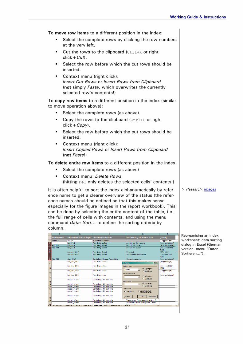
It is often helpful to sort the index alphanumerically by refer-ence name to get a clearer overview of the status (the refer-ence names should be defined so that this makes sense, especially for the figure images in the report workbook). This can be done by selecting the entire content of the table, i.e. the full range of cells with contents, and using the menu command Data: Sort… to define the sorting criteria by column.
> Research: Images
02_B-Mappe_A1
Reorganising an index worksheet: data sorting dialog in Excel (German version, menu "Daten: Sortieren...").
The research phase of a case study begins as soon as the building objects have been assigned to the participating stu-dents. This phase of collecting and sorting case information must necessarily be kept relatively short to leave enough weeks of the semester for the work of analysis and documen-tation. It should, therefore, be approached as systematically as possible.
To this end, the report workbooks (report_###.xls) have already been prepared in an initial form by the department and issued to the students together with the prescribed case study folders in an "object package" (see also "Folder Struc-ture and File Names"). Wherever the department had any pre-collected information on the given object, such as data from preliminary research or other student work, it is included in a separate folder: \material_ITI\.
> Rules: Folders & Files
A look at such a report workbook shows the following set of worksheets (see names on tabs):
General Contents Images
Sources
Polarities Editing
The worksheets highlighted bold above, that is, "Images" and "Sources," should already be used during the research phase of the case study and are, therefore, in detail in the next sub-sections. Digital data collected in the course of Internet research or from scanning printed materials are initially best saved in separate folders by source. Time is saved down the road by giving these folders names that correspond to reference names in the first column of the index worksheet, that is, by the author-date system (see also "Citing Literature & Other Sources"). All the other known information about the reference should be typed into the appropriate columns of the worksheet Sources as soon as possible, in order to avoid having to reconstruct it at the end of the term (reference information gets lost faster than one thinks). The same also applies to all the non-graphic sources of case information that are tapped during the research phase, such as literature, personal contacts, and so on.
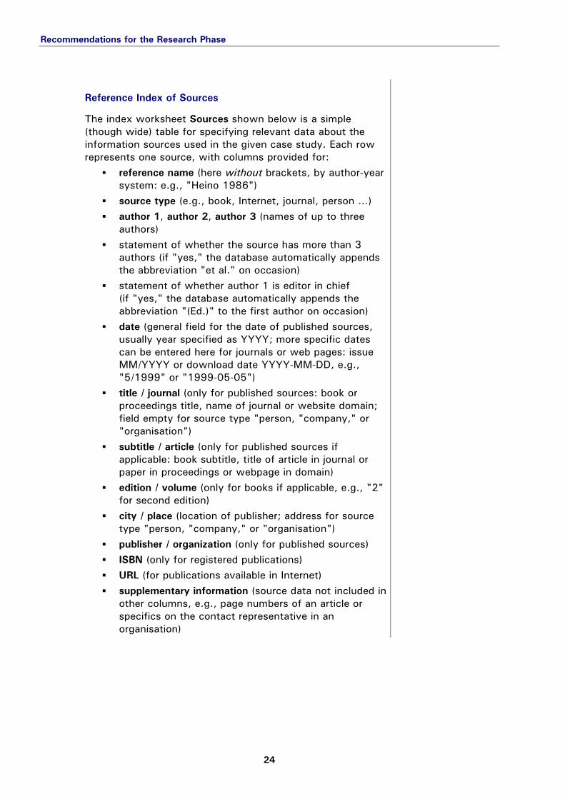
The index worksheet Sources shown below is a simple (though wide) table for specifying relevant data about the information sources used in the given case study. Each row represents one source, with columns provided for:
reference name (here without brackets, by author-year system: e.g., "Heino 1986")
source type (e.g., book, Internet, journal, person …) author 1, author 2, author 3 (names of up to three
authors) statement of whether the source has more than 3
authors (if "yes," the database automatically appends the abbreviation "et al." on occasion)
statement of whether author 1 is editor in chief (if "yes," the database automatically appends the abbreviation "(Ed.)" to the first author on occasion)
date (general field for the date of published sources, usually year specified as YYYY; more specific dates can be entered here for journals or web pages: issue MM/YYYY or download date YYYY-MM-DD, e.g., "5/1999" or "1999-05-05")
title / journal (only for published sources: book or proceedings title, name of journal or website domain; field empty for source type "person, "company," or "organisation")
subtitle / article (only for published sources if applicable: book subtitle, title of article in journal or paper in proceedings or webpage in domain)
edition / volume (only for books if applicable, e.g., "2" for second edition)
city / place (location of publisher; address for source type "person, "company," or "organisation")
publisher / organization (only for published sources) ISBN (only for registered publications) URL (for publications available in Internet) supplementary information (source data not included in
other columns, e.g., page numbers of an article or specifics on the contact representative in an organisation)
Recommendations for the Research Phase
25
02-01_r-wb_Sa
Report workbook: "Sources" worksheet (for indexing literature and other references), columns A-I …
02-01_r-wb_Sb
... columns J-P.
Note: General guidelines for using the "author-date system" are explained with examples (including exceptions) in "Rules & Standards: Citing Literature & Other Sources."
The standard syntax for reference names (Author YYYY) should be applied with the following exceptions:
Source type "Person" or "Organisation" (copyrightholder, e.g., for photos): only the last name or name of the organisation (no date).
Source type "Internet," if the author is unknown: cite the domain name (instead of an author) and the access year (e.g., "nextroom 2003"), whereby the specific access date should be noted in the source index (YYYY-MM-DD in date column).
Reference works, articles in journals, and other collections of work by unknown authors: cite the publishing organisation (e.g., name of a professional society) or name of the periodical (e.g., "Architectural Record") and the year, whereby the issue should be noted where appropriate in the source index (volume number instead of edition, YYYY-MM in date column for monthly periodicals).
> Rules: Citations
Recommendations for the Research Phase
26
Image Index of Figures images
The index worksheet Images is a simple table for specifying all graphics and other figures used to document and convey the case study results (see "Outlining & Formulating the Re-port in Chapters"). Each row represents one data file, with columns provided for:
reference name (figure label "Fig. ###" for link in report – here without brackets)*
file name (in folder \images\) figure type (classifying description of image content,
see also pictionary: other classifications) caption (as it should appear with the figure in the
report) source (link to an item in the Sources index, reference
name here in brackets, e.g., "[Heino 1986]")
> Report: Chapters
02-01_r-wb_I
Report workbook: "Im-ages" index worksheet.
* Note: The column for "reference name" is not relevant until the report is actually written in the final phase of the case study.
While processing the data collected in the research phase, it is convenient – and recommended – to have the correspond-ing report workbook open in the background, so that all fun-damental changes made to image files can be tracked concur-rently in the worksheet Images (especially the columns for file name, figure type, preliminary caption, and [source] references).
> Rules: File Names
The described working method saves having to repeatedly sift through the source folders and open files to review their con-tents in later stages of the case study. A partially completed example of a report workbook "in progress," together with the associated image files, is provided as an example report package in the download area (example_CS_B.zip).
2.2 CONTENT & WORKING METHODS FOR THE ANALYSIS PHASE
- Analysis Workbook
- Renderings
Buildings are highly complex physical entities that can be analysed – and even simulated – according to many different types of criteria. The term project for the concentration "Advanced Structures" focuses on case studies, in which the physical and technological characteristics of existing buildings are analysed with respect to the following main facets:
architecture and overall context, systems and efficiency criteria, construction and assembly technologies.
It is in the intellectual process of abstraction by means of modelling that students effectively "reconstruct" the design process and thus gain a deeper understanding of the physical and technical considerations underlying the finished product.
Details of working with standard CAD software will not be related here as students are free to use whatever CAD appli-cation they are comfortable with to produce their models -- as long as the meaning conveyed in such "3D diagrammes" is the result of systematic analysis and properly documented in a workbook (skill at using and access to some 3D programme is a prerequisite that can be safely assumed as given for both architecture and engineering students these days). The modelling principles are analogous to those for defining theoretical simulation models for the computer-based calcula-tion of structural and thermal behaviour. These results also serve as the knowledge base for studying the building's behaviour through simulation analysis in such courses as "IT-based Structural Design Methods" (see separate guide).
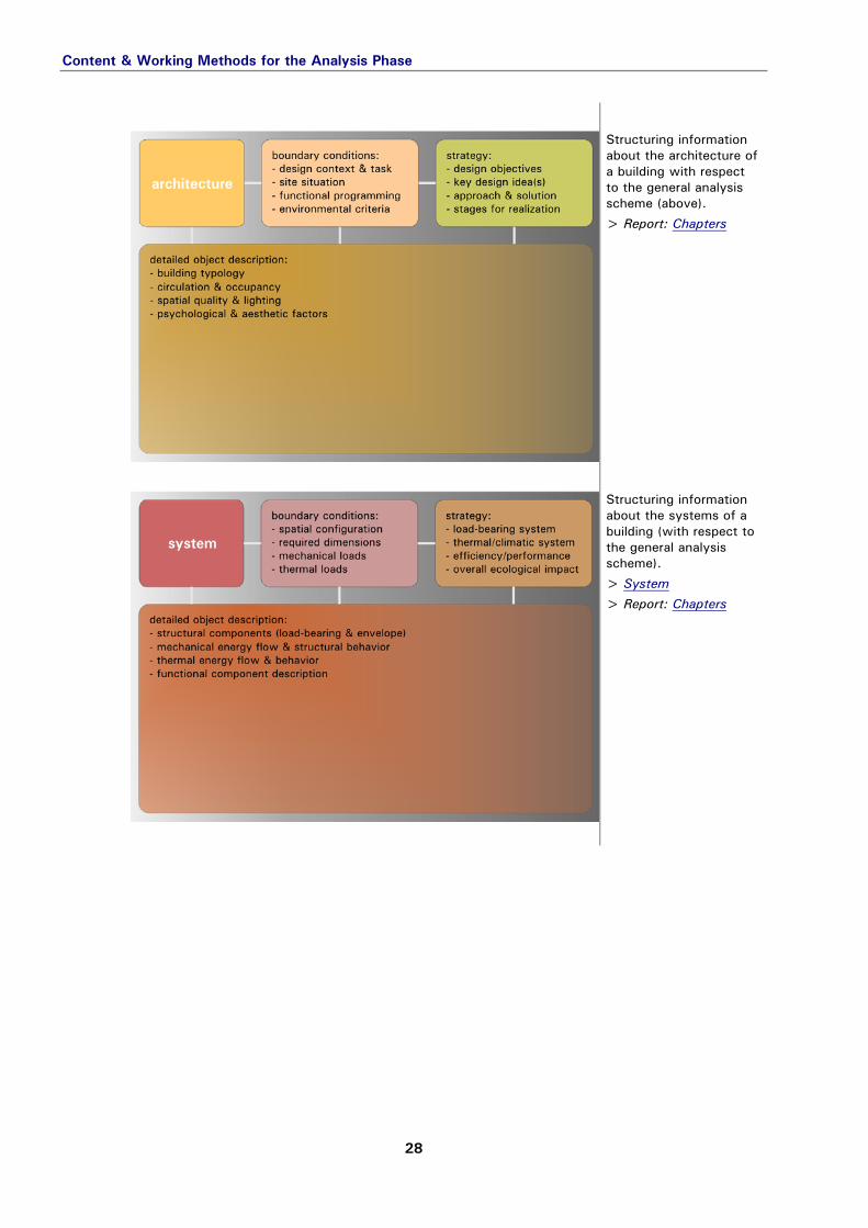
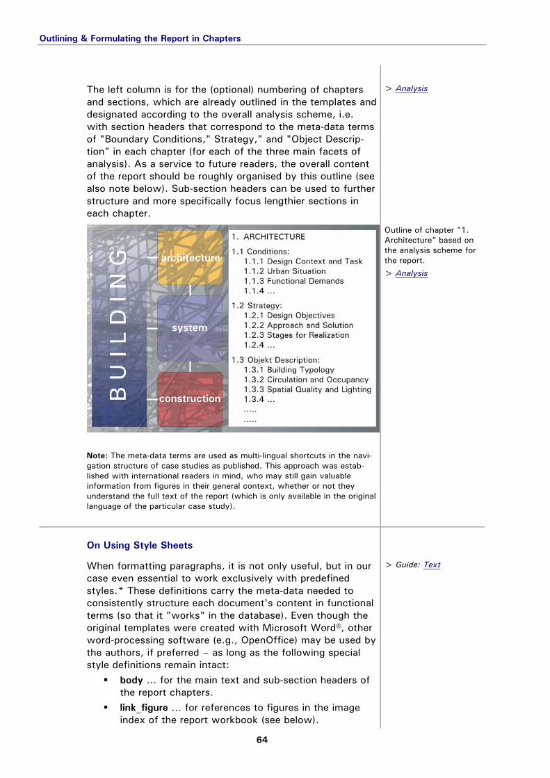
Structuring information about the architecture of a building with respect to the general analysis scheme (above).
> Report: Chapters
02-02_scheme_12
Structuring information about the systems of a building (with respect to the general analysis scheme).
> System > Report: Chapters
Content & Working Methods for the Analysis Phase
29
02-02_scheme_13
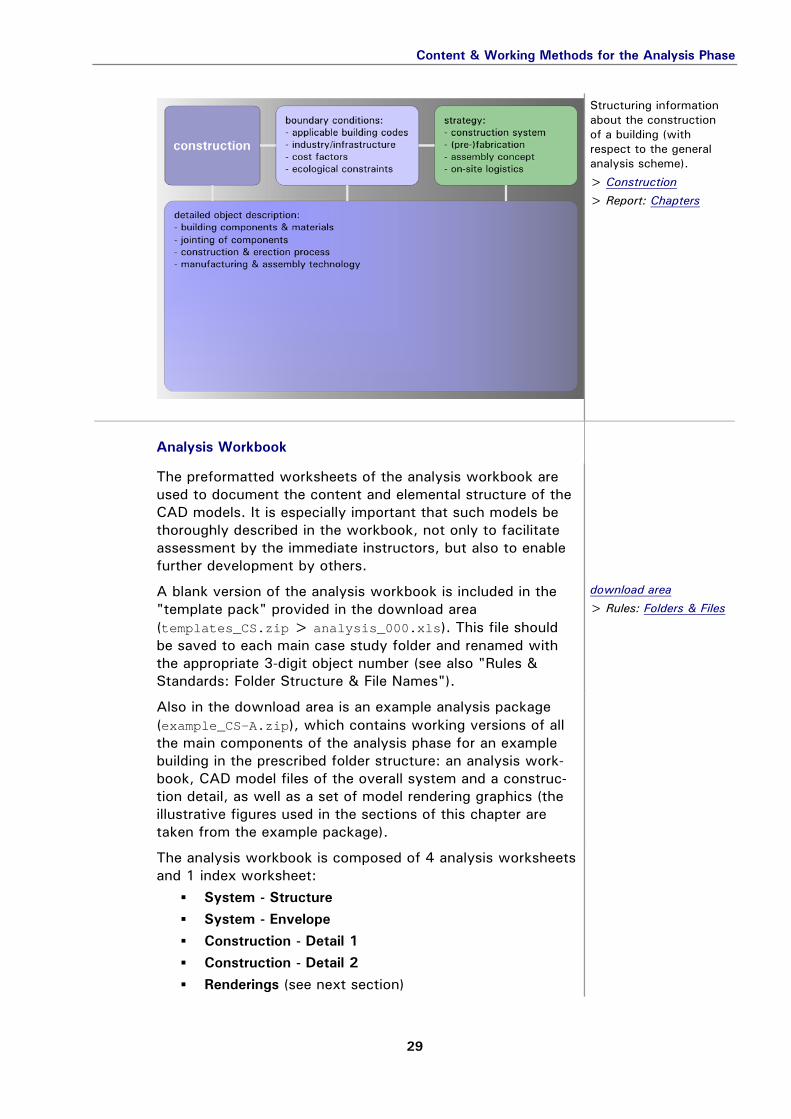
Structuring information about the construction of a building (with respect to the general analysis scheme).
> Construction > Report: Chapters
Analysis Workbook workbook
The preformatted worksheets of the analysis workbook are used to document the content and elemental structure of the CAD models. It is especially important that such models be thoroughly described in the workbook, not only to facilitate assessment by the immediate instructors, but also to enable further development by others.
A blank version of the analysis workbook is included in the "template pack" provided in the download area (templates_CS.zip > analysis_000.xls). This file should be saved to each main case study folder and renamed with the appropriate 3-digit object number (see also "Rules & Standards: Folder Structure & File Names").
download area > Rules: Folders & Files
Also in the download area is an example analysis package (example_CS-A.zip), which contains working versions of all the main components of the analysis phase for an example building in the prescribed folder structure: an analysis work-book, CAD model files of the overall system and a construc-tion detail, as well as a set of model rendering graphics (the illustrative figures used in the sections of this chapter are taken from the example package).
The analysis workbook is composed of 4 analysis worksheets and 1 index worksheet:
The analysis of a "complete building," that is, a structure with a thermal envelope, entails using both System work-sheets to describe the two fundamentally different types of models for the overall load-bearing structure and the building envelope. In most cases, the critical characteristics of the construction can be adequately explained in a model of one key detail that combines both structural and envelope com-ponents (the second Construction worksheet, Detail 2, may remain empty). The second System worksheet, Envelope, is to be neglected, logically, for "pure structures" without an essential thermal envelope (such as bridges). In such cases, it will generally be necessary to model two different details (using both Con-struction worksheets) to analyse the structure as completely as required.
> System > Construction
CAD Model Renderings renderings
Preliminary versions of (2D) graphic files can easily be inserted in the formatted worksheets to help visualise the analysis work in progress. To support an orderly documenta-tion of the modelling, such graphics are indexed in a separate table of model renderings. The index worksheet Renderings is a simple table for speci-fying everything that the database needs to know about the model representations used to visualise the analysis:
reference name (link in the analysis worksheets), image file (full file name in folder \CAD\2d\), description (e.g., label of the building component or
assembly step shown in the image), model file (full file name in folder \CAD\), and specification of which parts of the 3D model are
rendered by layer name(s).
> Guide: Graphics
02-02_a-wb_R
Analysis workbook: "Renderings" index worksheet.
During the process of analysis development with the other worksheets, it is often useful to have thumbnail sketches or model renderings of the components as a visual reference. The last columns of the analysis worksheets provide fields for including such thumbnails in each component row, whereby
Content & Working Methods for the Analysis Phase
31
the entire worksheet is formatted such that it can be printed out in landscape format for preliminary work on paper. The modelling work is so graphically intertwined with the analysis workbook in the following steps: Set up the model such that a consistent view of all the
components is enabled. Deactivate all layers not relevant to the given rendering
(depending on the row and column in worksheet).
Export the view as an image file to the folder
\CAD\2d\*.*, preferably in a scalable vector graphic format (which can be better processed later for use in the report, e.g., wmf – see also "Rules & Standards: File Formats"), and with a meaningful name* preceded by a sequence number and a code for the model type (e.g., env_03a_glazing).
> Rules & Standards
Register the image file in the Renderings index worksheet
and enter the reference name in brackets in the cell where the graphic should be inserted in the analysis worksheet.
Insert the rendering using the menu command Insert: Graphics: From File …, and resize it to fit in the desig-nated cell, covering (but not replacing!) the reference text.
The final set of model renderings is then moved to an appro-priately labelled subfolder (e.g., \CAD\2d\structure\).
Important note to avoid excessively "bloated" and unwieldy workbook files: If the original renderings were generated in a bitmap format (e.g., bmp), a set of scaled down, thumbnail versions should created and saved to a separate subfolder for insertion in the workbook (\CAD\2d\thumbs\). The reference, however, still applies to the original size files.
* Use only standard characters in naming the image file (1-9, a-z, _, -). Do not use spaces, punctuation (?, !, …), symbols or other special characters (umlauts, ß, &, …)!
Renderings used in overall system analysis (example model).
3D Model of the Load-bearing Structure structure
The worksheet System - Structure is for documenting the structural components of the building’s load-bearing system. Only components identified as essentially load bearing are included in this part of the overall system model, abstracted according to dimensional characteristics. This means that, in the sense of "structurally active" force vectors (1D) or force fields (2D), the analysis entails modelling the spatial configu-ration of
linear components as simple lines without cross-section and
surface components as planes without thickness.
02-
Characteristics of load-bearing systems: linear vs. surface elements.
The process of dissecting the structure into its constituent components is reflected in the modelling stages, in which the system is progressively refined and differentiated by separating sets of related components in layers (see also example package A: \CAD\system.dwg). In order to clarify the analysis visually, both in the 3D model and in 2D ren-derings, it is recommended that each such layer be assigned a unique colour (= colour code for component types).
02-02-01_model_11
System model of the load-bearing structure (screenshot of example).
[Wolfsgruber]
Further information on each structural layer is then docu-mented in a component row of the System - Structure work-sheet, which includes columns for specifying a number of relevant characteristics. The narrower rows between com-ponents are for describing the connection between two adja-cent components (where applicable).
02-02-01_a-wb_SS
Analysis workbook: "Structure" worksheet (for analysing compo-nents of the load-bearing structure).
In particular, text entered in the columns for
material / joint fastener and structural system / joint (structural type)
should define the structural component or connecting joint in classifying terms.
> Rules: Classifications
Predefined terminologies for these aspects are provided in the online "pictionaries" and should be consulted in the process of formulating such worksheet entries (more in "Rules & Standards: Terminology of Classification").
archistructura: pictionaries
As the CAD model is finalised, digital renderings should be made and inserted in the last columns – with a reference to an entry in the Renderings index worksheet – to visually document the individual components in two manners:
The first shows the component in the context of its sup-porting components; the second without any surrounding structure.
The final set of model renderings is then moved to a sub-folder for the structural system (\CAD\2d\structure\).
3D Model of the Thermal Envelope envelope
The worksheet System - Envelope is for documenting the enclosure components of the building’s thermal envelope. Only components identified as essential to the thermal sepa-ration of spaces are included in this part of the overall sys-tem model, abstracted in terms of a simple sheet model. This means that, in the sense of "thermally active" resistance to linear heat transfer (1D vectors through 2D planes), the analysis entails modelling the spatial configuration of
surface components as planes without thickness. The overall building geometry is fundamentally simplified to theoretical surfaces that demarcate the boundary between adjacent volumes of distinct temperature zones, that is, between interior and exterior, as well as between heated/cooled and "free-running" spaces (e.g., boundary between atrium and adjacent air-conditioned rooms).
02-02-01_scheme_40
Differentiating the components of a building envelope by thermal criteria.
Though the exact geometry of this thermal boundary surface within the construction can only be determined through detailed simulation analysis, a plausible first approximation can be modelled simply based on the geometry of the main insulating layer within the relevant construction components. In climates that are characterised by a significant heating demand (e.g., Austrian winters), the assumption that heat flows from interior to exterior spaces is valid enough (most of the time). Simplified calculations "on the safe side" will
Analytically Modelling the Overall System
36
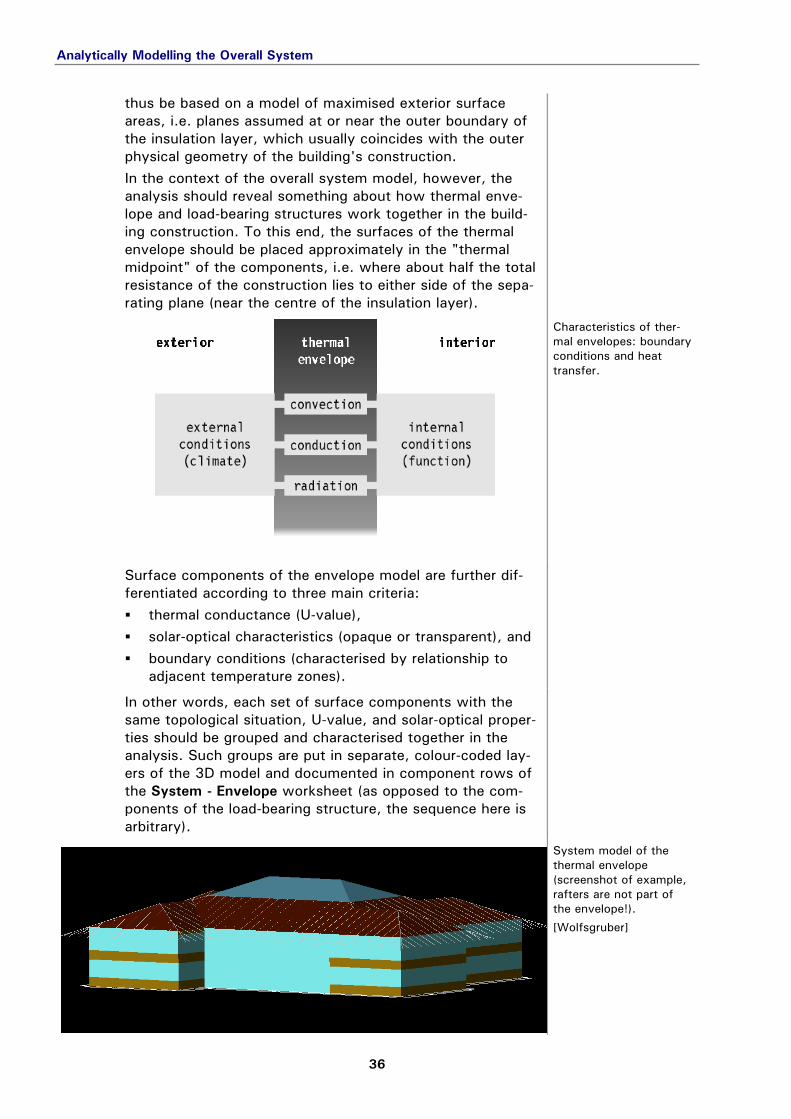
thus be based on a model of maximised exterior surface areas, i.e. planes assumed at or near the outer boundary of the insulation layer, which usually coincides with the outer physical geometry of the building's construction. In the context of the overall system model, however, the analysis should reveal something about how thermal enve-lope and load-bearing structures work together in the build-ing construction. To this end, the surfaces of the thermal envelope should be placed approximately in the "thermal midpoint" of the components, i.e. where about half the total resistance of the construction lies to either side of the sepa-rating plane (near the centre of the insulation layer).
02-02-01_scheme_50
Characteristics of ther-mal envelopes: boundary conditions and heat transfer.
Surface components of the envelope model are further dif-ferentiated according to three main criteria: thermal conductance (U-value), solar-optical characteristics (opaque or transparent), and boundary conditions (characterised by relationship to
adjacent temperature zones).
In other words, each set of surface components with the same topological situation, U-value, and solar-optical proper-ties should be grouped and characterised together in the analysis. Such groups are put in separate, colour-coded lay-ers of the 3D model and documented in component rows of the System - Envelope worksheet (as opposed to the com-ponents of the load-bearing structure, the sequence here is arbitrary).
02-02-01_model_12
System model of the thermal envelope (screenshot of example, rafters are not part of the envelope!).
[Wolfsgruber]
Analytically Modelling the Overall System
37
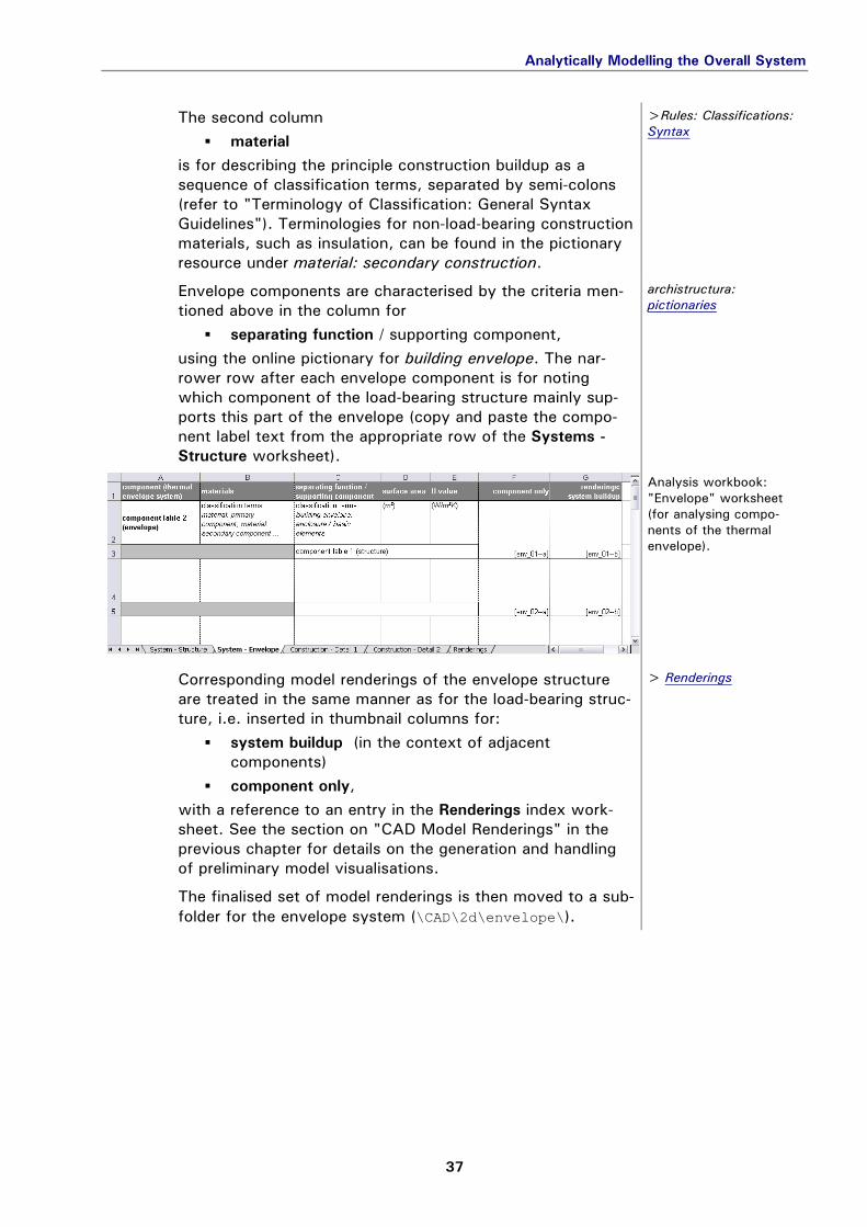
The second column
material is for describing the principle construction buildup as a sequence of classification terms, separated by semi-colons (refer to "Terminology of Classification: General Syntax Guidelines"). Terminologies for non-load-bearing construction materials, such as insulation, can be found in the pictionary resource under material: secondary construction.
>Rules: Classifications: Syntax
Envelope components are characterised by the criteria men-tioned above in the column for
separating function / supporting component, using the online pictionary for building envelope. The nar-rower row after each envelope component is for noting which component of the load-bearing structure mainly sup-ports this part of the envelope (copy and paste the compo-nent label text from the appropriate row of the Systems - Structure worksheet).
archistructura: pictionaries
02-02-01_a-wb_SE
Analysis workbook: "Envelope" worksheet (for analysing compo-nents of the thermal envelope).
Corresponding model renderings of the envelope structure are treated in the same manner as for the load-bearing struc-ture, i.e. inserted in thumbnail columns for:
system buildup (in the context of adjacent components)
component only, with a reference to an entry in the Renderings index work-sheet. See the section on "CAD Model Renderings" in the previous chapter for details on the generation and handling of preliminary model visualisations.
> Renderings
The finalised set of model renderings is then moved to a sub-folder for the envelope system (\CAD\2d\envelope\).
Renderings used in construction analysis (example model).
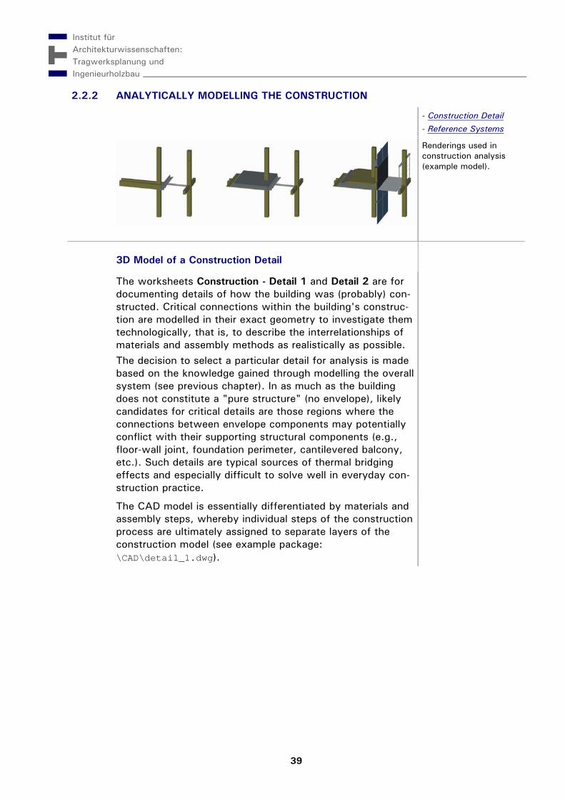
3D Model of a Construction Detail construction
The worksheets Construction - Detail 1 and Detail 2 are for documenting details of how the building was (probably) con-structed. Critical connections within the building's construc-tion are modelled in their exact geometry to investigate them technologically, that is, to describe the interrelationships of materials and assembly methods as realistically as possible. The decision to select a particular detail for analysis is made based on the knowledge gained through modelling the overall system (see previous chapter). In as much as the building does not constitute a "pure structure" (no envelope), likely candidates for critical details are those regions where the connections between envelope components may potentially conflict with their supporting structural components (e.g., floor-wall joint, foundation perimeter, cantilevered balcony, etc.). Such details are typical sources of thermal bridging effects and especially difficult to solve well in everyday con-struction practice.
The CAD model is essentially differentiated by materials and assembly steps, whereby individual steps of the construction process are ultimately assigned to separate layers of the construction model (see example package: \CAD\detail_1.dwg).
Construction model of the primary components of a building detail (screenshot of example).
[Wolfsgruber]
02-02-02_model_22
Construction model of the primary and secon-dary elements of a building detail (screen-shot of example).
[Wolfsgruber]
Analytically Modelling the Construction
41
In the worksheet, these material layers are documented sequentially in element rows. The narrower rows between the elements are for describing the fastening method from one assembly step to the next (where applicable).
02-02-02_a-wb_C
Analysis workbook: "Construction" work-sheet (for analysing building components in detail).
The characteristics of each element – and each connection between elements – are given in columns for different tech-nological aspects. As for the other worksheets, the terminol-ogy for the column
material / joint fastener should largely conform to the classification system staked out in the online pictionary for material (refer to "Rules & Standards: Terminology of Classification").
> Rules: Classifications: Study Aids archistructura: pictionaries
Since no such pictionaries are currently available for
construction method and component type / jointing method,
the terms entered here must all be taken from other sources of information (books, lectures, experience …). Key word chains are welcome as classifying terms, especially if they adhere to the recommended syntax for hierarchical semantic expressions.
> Rules: Classifications: Syntax
The last column,
construction sequence, is for inserting (references to) graphics that illustrate the construction model in assembly steps.
The procedure for generating, indexing and otherwise han-dling model visualisations is the same in this worksheet as in the rest of the analysis workbook (except that, as a rule, bitmaps often prove more practical to render details legibly than vector graphic formats). Recommended procedures are described more thoroughly in "Content & Working Methods for the Analysis Phase: CAD Model Renderings."
> Renderings
Each finalised set of model renderings is then moved to a subfolder for the construction detail (\CAD\2d\detail_1\, \detail_2\).
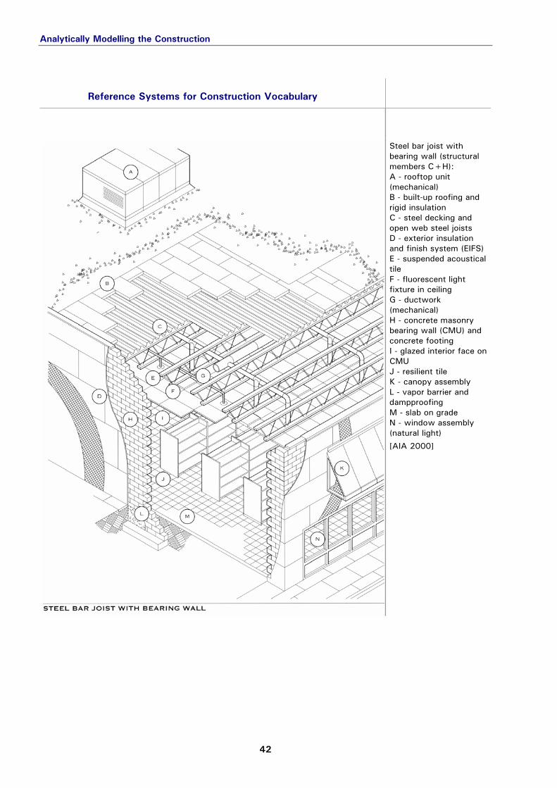
Reference Systems for Construction Vocabulary systems
systems
02-02-02_AIA-00_013
Steel bar joist with bearing wall (structural members C+H): A - rooftop unit (mechanical) B - built-up roofing and rigid insulation C - steel decking and open web steel joists D - exterior insulation and finish system (EIFS) E - suspended acoustical tile F - fluorescent light fixture in ceiling G - ductwork (mechanical) H - concrete masonry bearing wall (CMU) and concrete footing I - glazed interior face on CMU J - resilient tile K - canopy assembly L - vapor barrier and dampproofing M - slab on grade N - window assembly (natural light)
[AIA 2000]
Analytically Modelling the Construction
43
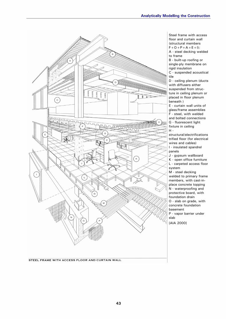
02-02-02_AIA-00_014
Steel frame with access floor and curtain wall (structural members F+O+P+A+E+I): A - steel decking welded to frame B - built-up roofing or single-ply membrane on rigid insulation C - suspended acoustical tile D - ceiling plenum (ducts with diffusers either suspended from struc-ture in ceiling plenum or placed in floor plenum beneath ) E - curtain wall units of glass/frame assemblies F - steel, with welded and bolted connections G - fluorescent light fixture in ceiling H - structural/electrifications trified floor (for electrical wires and cables) I - insulated spandrel panels J - gypsum wallboard K - open office furniture L - carpeted access floor system M - steel decking welded to primary frame members, with cast-in-place concrete topping N - waterproofing and protective board, with foundation drain O - slab on grade, with concrete foundation basement P - vapor barrier under slab
[AIA 2000]
Analytically Modelling the Construction
44
02-02-02_AIA-00_015
Staggered steel truss (structural members I+C+D+M): A - rigid insulation, single-ply roofing and ballast B - ducts with diffusers and sprinkler system (mechanical) C - precast hollow-core concrete plank deck D - staggered story-high steel trusses E - tiled flooring on floor planks with grouted joints F - gypsum wallboard G - window assembly H - precast shear panels I - steel columns K - carpeting on floor planks with grouted joints L - precast concrete panels M - slab on grade, with foundation N - vapor barrier, waterproofing and protective board
[AIA 2000]
Analytically Modelling the Construction
45
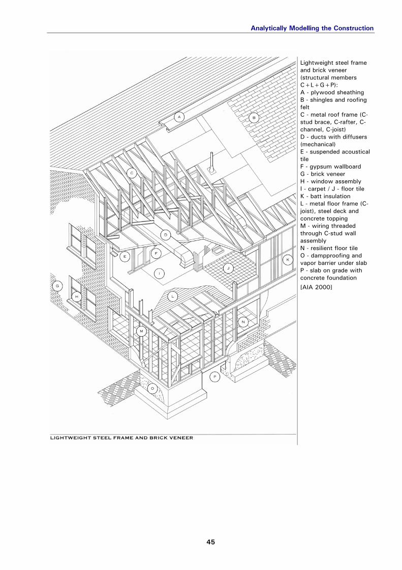
02-02-02_AIA-00_016
Lightweight steel frame and brick veneer (structural members C+L+G+P): A - plywood sheathing B - shingles and roofing felt C - metal roof frame (C-stud brace, C-rafter, C-channel, C-joist) D - ducts with diffusers (mechanical) E - suspended acoustical tile F - gypsum wallboard G - brick veneer H - window assembly I - carpet / J - floor tile K - batt insulation L - metal floor frame (C-joist), steel deck and concrete topping M - wiring threaded through C-stud wall assembly N - resilient floor tile O - dampproofing and vapor barrier under slab P - slab on grade with concrete foundation
[AIA 2000]
Analytically Modelling the Construction
46
02-02-02_AIA-00_017
Wood roof truss and wood floor truss (structural members B+G+F+K): A - shingles, roofing felt, with metal flashing B - wood roof truss and plywood sheathing C - acoustical tile D - gypsum wallboard E - batt insulation F - wood frame and sheathing G - wood floor truss and plywood subfloor H - ducts and diffusers (mechanical) I - lapped wood siding J - window assembly K - slab on grade, concrete masonry foundation wall and concrete footing L - carpet M - below-slab perimeter ducts (mechanical)
[AIA 2000]
Analytically Modelling the Construction
47
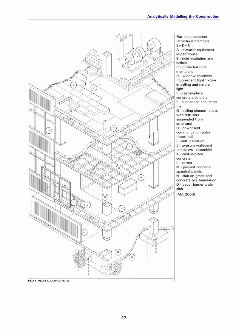
02-02-02_AIA-00_018
Flat plate concrete (structural members E+K+N): A - elevator equipment in penthouse B - rigid insulation and ballast C - protected roof membrane D - window assembly (fluorescent light fixture in ceiling and natural light) E - cast-in-place concrete slab plate F - suspended acoustical tile G - ceiling plenum (ducts with diffusers suspended from structure) H - power and communcation poles (electrical) I - batt insulation J - gypsum wallboard (metal wall assembly) K - cast-in-place concrete L - carpet M - precast concrete spandrel panels N - slab on grade and concrete pile foundation O - vapor barrier under slab
[AIA 2000]
Analytically Modelling the Construction
48
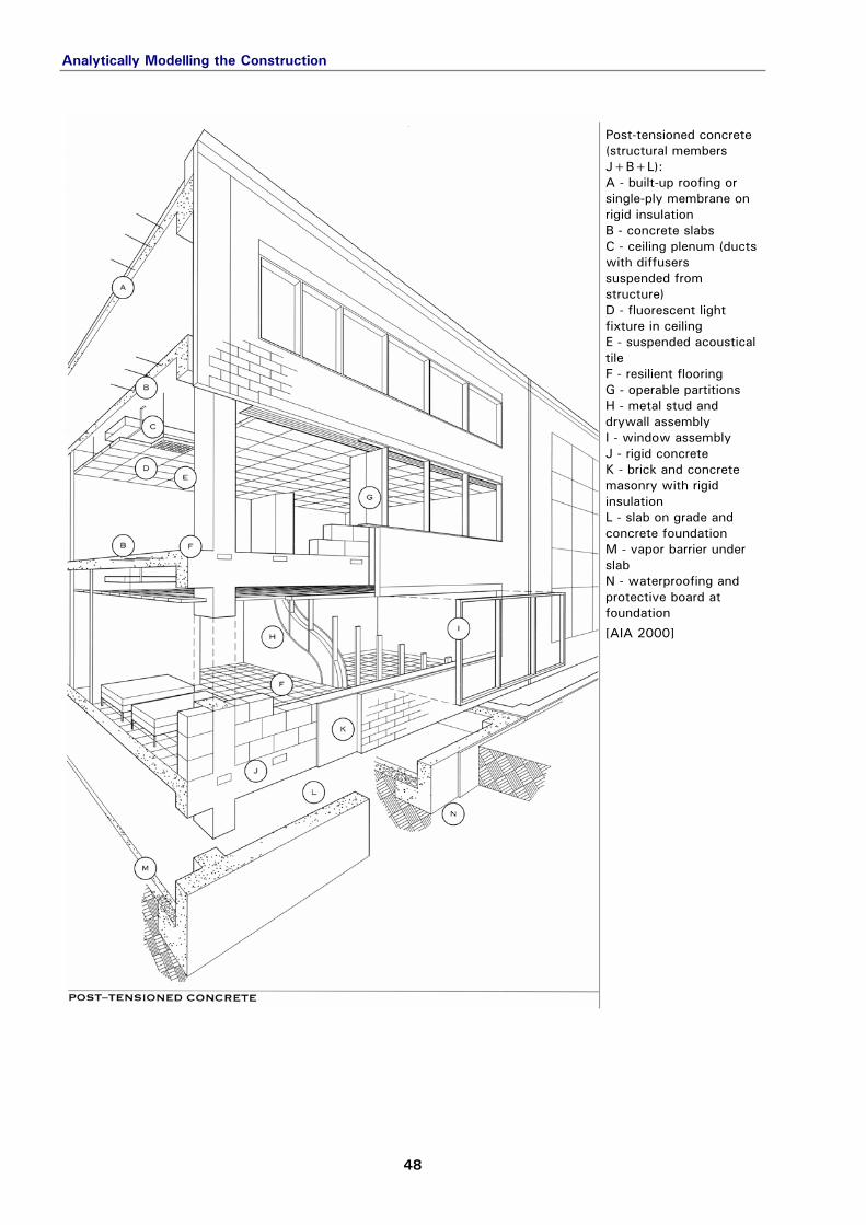
02-02-02_AIA-00_019
Post-tensioned concrete (structural members J+B+L): A - built-up roofing or single-ply membrane on rigid insulation B - concrete slabs C - ceiling plenum (ducts with diffusers suspended from structure) D - fluorescent light fixture in ceiling E - suspended acoustical tile F - resilient flooring G - operable partitions H - metal stud and drywall assembly I - window assembly J - rigid concrete K - brick and concrete masonry with rigid insulation L - slab on grade and concrete foundation M - vapor barrier under slab N - waterproofing and protective board at foundation
[AIA 2000]
Analytically Modelling the Construction
49
02-02-02_AIA-00_020
Precast concrete frame (structural members D+B+E+F): A - concrete topping slab B - prestressed prefab concrete double T C - fluorescent light fixtures attached to structure D - prestressed prefab concrete columns and spandrel beams E - cast-in-place concrete vertical circulation F - slab on grade, with cast-in-place concrete piles G - equipment for hydraulic elevator
[AIA 2000]
Analytically Modelling the Construction
50
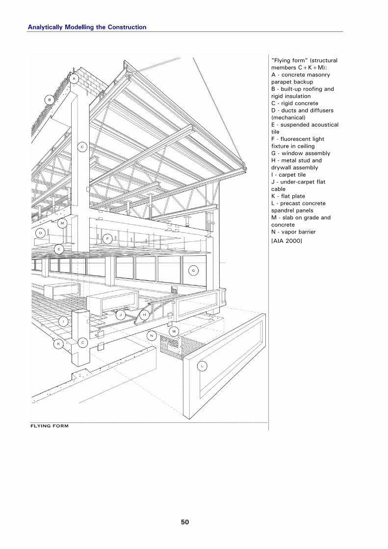
02-02-02_AIA-00_021
"Flying form" (structural members C+K+M): A - concrete masonry parapet backup B - built-up roofing and rigid insulation C - rigid concrete D - ducts and diffusers (mechanical) E - suspended acoustical tile F - fluorescent light fixture in ceiling G - window assembly H - metal stud and drywall assembly I - carpet tile J - under-carpet flat cable K - flat plate L - precast concrete spandrel panels M - slab on grade and concrete N - vapor barrier
[AIA 2000]
Analytically Modelling the Construction
51
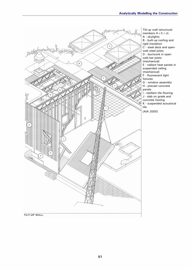
02-02-02_AIA-00_022
Tilt-up wall (structural members H+C+J): A - skylights B - built-up roofing and rigid insulation C - steel deck and open-web steel joists D - ductwork in open-web bar joists (mechanical) E - radiant heat panels in suspended ceiling (mechanical) F - fluorescent light fixtures G - window assembly H - precast concrete panels I - resilient tile flooring J - slab on grade and concrete footing K - suspended acoustical tile
[AIA 2000]
Analytically Modelling the Construction
52
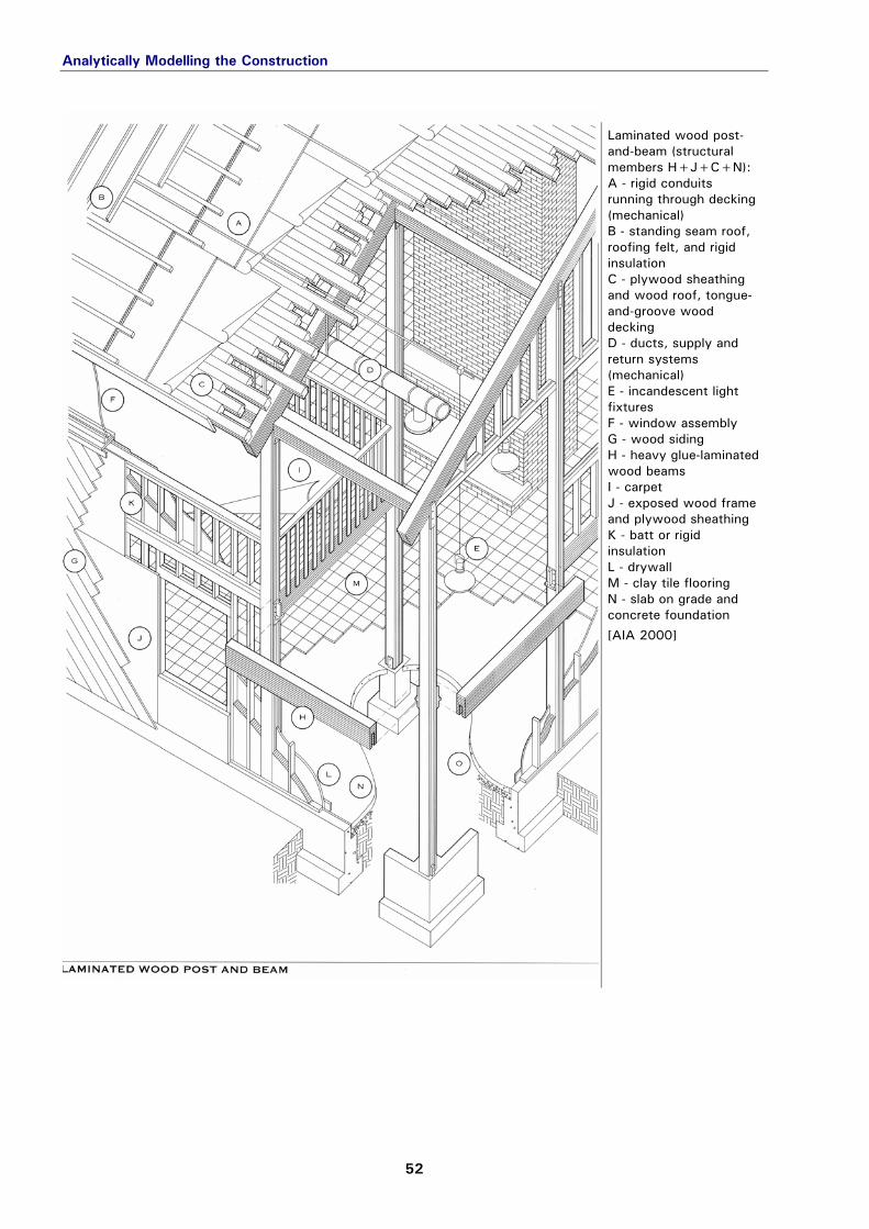
02-02-02_AIA-00_023
Laminated wood post-and-beam (structural members H+J+C+N): A - rigid conduits running through decking (mechanical) B - standing seam roof, roofing felt, and rigid insulation C - plywood sheathing and wood roof, tongue-and-groove wood decking D - ducts, supply and return systems (mechanical) E - incandescent light fixtures F - window assembly G - wood siding H - heavy glue-laminated wood beams I - carpet J - exposed wood frame and plywood sheathing K - batt or rigid insulation L - drywall M - clay tile flooring N - slab on grade and concrete foundation
[AIA 2000]
Analytically Modelling the Construction
53
02-02-02_AIA-00_024
Lightweight mobile modular (structural members J+C+N): A - rooftop unit (mechanical) B - sheet metal roofing and metal cap flashing C - glue-laminated beams and wood deck D - batt insulation E - insulated ducts (mechanical) F - suspended acoustical tile G - fluorescent light fixtures in ceiling H - window assembly I - factory installed systems, hooked up on site (mechanical) J - wood frame and sheathing K - drywall L - electric baseboard heaters M - resilient flooring N - plywood subfloor on lateral steel beams O - vapor barrier
[AIA 2000]
Analytically Modelling the Construction
54
02-02-02_AIA-00_025
Space frame (structural members B+F+I): A - built-up roofing and rigid insulation B - metal space frame with steel decking C - electrical conduits D - incandescent light fixtures E - glass block panel F - concrete masonry bearing wall G - brick veneer and rigid insulation H - wood flooring I - slab on grade and concrete foundation J - vapor barrier
[AIA 2000]
Analytically Modelling the Construction
55
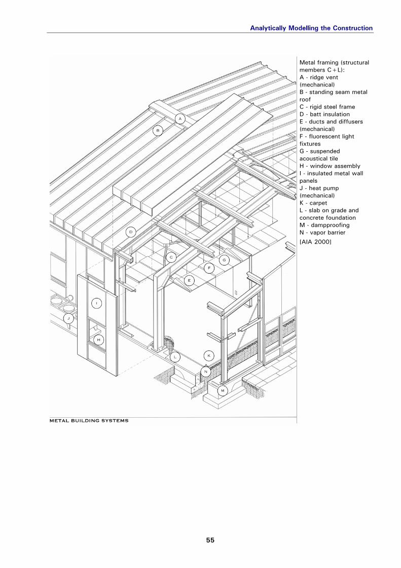
02-02-02_AIA-00_026
Metal framing (structural members C+L): A - ridge vent (mechanical) B - standing seam metal roof C - rigid steel frame D - batt insulation E - ducts and diffusers (mechanical) F - fluorescent light fixtures G - suspended acoustical tile H - window assembly I - insulated metal wall panels J - heat pump (mechanical) K - carpet L - slab on grade and concrete foundation M - dampproofing N - vapor barrier
[AIA 2000]
Analytically Modelling the Construction
56
02-02-02_AIA-00_027
Tension fabric (structural members B+A+C+F): A - steel cables in fabric sleeves B - noncombustible fabric membrane C - steel masts D - incandescent lighting fixtures E - slab on grade F - pivoted mast base and concrete footing G - vapor barrier
2.3 DOCUMENTING THE CASE STUDY IN A COMPLETE REPORT
- Contents
- Editing
At the beginning of the term project, report workbooks (report_###.xls) were prepared with some basic building information by the department and issued to the participating students together with the prescribed case study folders.
Familiarity with parts of the report workbook should already be gained during the research phase of case studies, in par-ticular, the two index worksheets for information sources and images.
> Research
Treatment of the General and Polarities worksheets is explained in detail in the section "Basic Building & Case Study Information." The purpose of the technical worksheets Contents and Editing are briefly related in the following.
> Basics
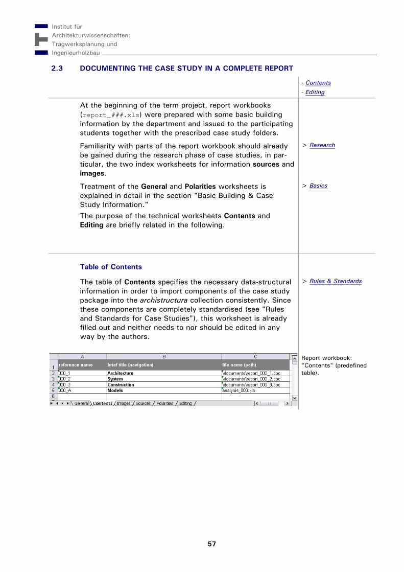
Table of Contents contents
The table of Contents specifies the necessary data-structural information in order to import components of the case study package into the archistructura collection consistently. Since these components are completely standardised (see "Rules and Standards for Case Studies"), this worksheet is already filled out and neither needs to nor should be edited in any way by the authors.
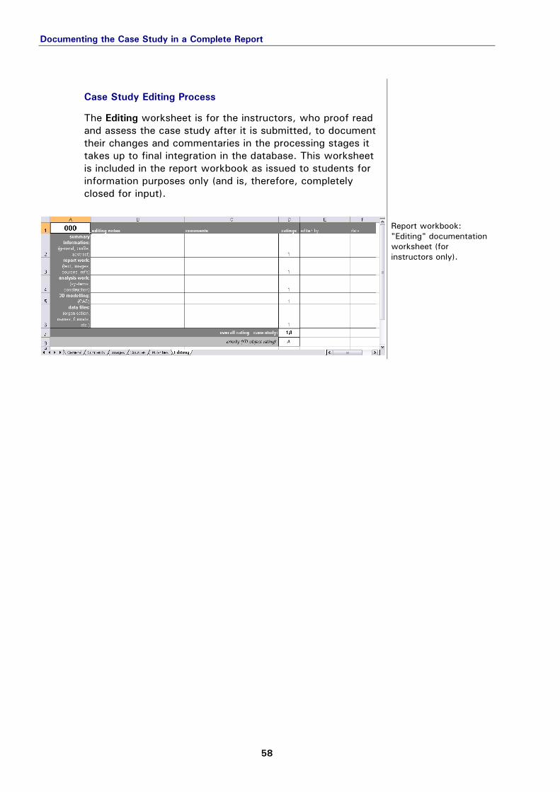
The Editing worksheet is for the instructors, who proof read and assess the case study after it is submitted, to document their changes and commentaries in the processing stages it takes up to final integration in the database. This worksheet is included in the report workbook as issued to students for information purposes only (and is, therefore, completely closed for input).
The first worksheet of the report workbook, General, is essentially a form for indexing information about the building object and the particular case study. Most of the fields in this worksheet are self-explanatory. Empty fields should be filled out and incorrect entries edited by the case study author(s) where applicable.
Standardised terminology should be entered in fields used to specifying meta-data about the building, in particular for the following information:
Country (Code): ISO country code (e.g., AT for Austria)
> Rules: Classification
Structure Type: refer to online pictionary for design
task: structure type. Construction: refer to pictionary for load-bearing
structure to name the dominant structural system(s); alternatively, if appropriate, a term for the construc-tion system can be entered here (see also reference systems in the section on "Analytically Modelling the Construction").
Primary Material: refer to pictionary for materials: primary construction
Function: refer to pictionary for design task: project type / function
Since information on the overall size of a building project cannot generally be defined in a single measure, a number of alternative fields are provided in the category "Scope," which should be filled out as completely as the available information allows. The last set of fields at the bottom of the form document the academic context of the case study. Authors enter their name (Last, First) and student ID number here.
archistructura: pictionaries > Construction: Reference Systems
Note: The relatively large (dark grey) field to the upper right should already contain a key image for the building object inserted over the standard reference here ("[key image]") – this refer-ence tag should not be deleted or modified! The corresponding graphic file is already indexed in the first row of the Figures worksheet and should be left intact where it can be found:
in the \images\ folder, saved in JPEG format (medium quality/compression), named with the three-digit object number (###.jpg).
02-03-01_033
Key image of the exam-ple project (building no. 033).
The Polarities worksheet is a spreadsheet version of the questionnaire for assessing semantic-associative impressions of a building (refer to "Introduction to Semantic Profiles" for details). Authors should wait until the end of the case study, when the analysis work and a draft of the report have been com-pleted, before evaluating the 46 semantic differentials cov-ered here (so that this data may reflect an "expert opinion" of the building).
> Semantic Profiles
02-03-01_r-wb_P
Report workbook: "Polarities" worksheet (for recording profile assessment by case study author).
Instructions:
Select a polarity's "0" cell, drag the anchor (lower right corner) towards the left or right adjective as far as it reflects the association to you, i.e. from 0=neutral to 3=strong.
To correct input: Either use the menu command Edit: Undo or select empty cells to copy and paste them into the incor-rectly filled out cells via the clipboard; then re-enter the value as described above.
2.3.2 OUTLINING & FORMULATING THE REPORT IN CHAPTERS
- Style Sheets
- Sources & Figures
The three main aspects of analysis – 1. Architecture, 2. Sys-tem und 3. Construction – are revisited in the case study report phase, when all the knowledge gained about the building is pulled together and adequately structured for archival in (and publication from) the archistructura database.
> Contents
Since the process of writing is much less tedious with a word-processing programme than in the spreadsheet format, the procedure for report documentation was revised from earlier versions: chapter contents are no longer inserted into (cumbersome) worksheets, but rather written in strictly for-matted Word® documents.
The left column is for the (optional) numbering of chapters and sections, which are already outlined in the templates and designated according to the overall analysis scheme, i.e. with section headers that correspond to the meta-data terms of "Boundary Conditions," Strategy," and "Object Descrip-tion" in each chapter (for each of the three main facets of analysis). As a service to future readers, the overall content of the report should be roughly organised by this outline (see also note below). Sub-section headers can be used to further structure and more specifically focus lengthier sections in each chapter.
> Analysis
02-03-02_scheme_21
Outline of chapter "1. Architecture" based on the analysis scheme for the report.
> Analysis
Note: The meta-data terms are used as multi-lingual shortcuts in the navi-gation structure of case studies as published. This approach was estab-lished with international readers in mind, who may still gain valuable information from figures in their general context, whether or not they understand the full text of the report (which is only available in the original language of the particular case study).
On Using Style Sheets styles
When formatting paragraphs, it is not only useful, but in our case even essential to work exclusively with predefined styles.* These definitions carry the meta-data needed to consistently structure each document's content in functional terms (so that it "works" in the database). Even though the original templates were created with Microsoft Word®, other word-processing software (e.g., OpenOffice) may be used by the authors, if preferred – as long as the following special style definitions remain intact:
body … for the main text and sub-section headers of the report chapters.
link_figure … for references to figures in the image index of the report workbook (see below).
> Guide: Text
Outlining & Formulating the Report in Chapters
65
caption … for describing figures in the context of the document content (the caption contained in the image index is displayed when figures are presented indi-vidually "out of context," e.g., in a separate window).
link_source … for references to sources (see below). other special styles for predefined content: chapter,
section, link_report, num_chapter und num_section. Though of no immediate concern to case study authors, these styles are absolutely essential to con-tent management and should under no circumstances be deleted or renamed in the document style sheet!
All of the above-mentioned styles may be used in report documents together with basic character formatting styles (e.g., bold, italic, ordered or unordered lists, etc.), as demon-strated in the "dummy text" of the templates. The normal (default) font is Univers 11 pt, left-adjusted. Paragraphs con-stituting a sub-section header should be highlighted in bold type. Any text copied from other documents with a different style needs to be explicitly reformatted in the report docu-ment by selecting and applying the appropriate predefined style (one of the above). *Word-processing tip: A new paragraph is created by hitting Enter once. Inserting simple line breaks (e.g., with the combination Shift+Enter or the menu command Insert: Manual Break…) does not cre-ate paragraphs that can be separately formatted. A document can easily be checked for such "invisible" char-acters by turning on the formatting marks ("¶" button)!
02-03-02_r-doc_11
Formatting a report document using styles predefined in the tem-plate and displayed in the formatting task pane (German version, menu "Format: Formatvorlagen…").
Outlining & Formulating the Report in Chapters
66
Attention: The overall layout in the three-column table primarily serves database requirements and should be considered only as a working draft for printing purposes. Specifically, this means that certain "junk" characters often used to cosmetically improve the layout of a print version should be avoided, in particular: Do not insert any page or section breaks (which also
break the table apart). Do not induce line or page breaks by inserting super-
fluous space or paragraph characters (and leave out automatic/conditional hyphenation).
Paragraphs containing a reference name to a figure (style: link_figure) should be written exactly as in the image index, without any additional spaces or other characters.
Figure images may be inserted for drafting purposes, but these typically bloat the file unnecessarily in most word-processing programmes (they are automatically removed anyway when the file is converted for database import – the reference name is what really matters here).
A predefined style must be applied to every paragraph (unit of information) that the document contains; any remaining "leftovers" with default or other styles get lost in the pipeline – so check the formats of everything you've written in each document before submitting!
References to Sources and Figures references
Literature and other sources can be inserted as a reference name in brackets where applicable in the body text (e.g., "Blabla is blabla according to blabla [Heino 1986]"). Embed-ded in this form, the reference is just information for the reader, but cannot be hyperlinked to the reference section of the report. In order to define an automatic link to an item in the Sources index worksheet, the reference must be written in a separate paragraph (style: link_source) and the text string between the brackets must exactly match the refer-ence name listed in the index. By analogy, photos and other figures are inserted in the report as references to the Images index (style: link_figure). A separate row should be inserted for each figure so that the respective captions can be consistently positioned in the column to the right (style: caption): To insert a new row above an existing one, select an
entire row (cursor beyond left edge of table) and use the Table menu command Insert: Row, or the equivalent con-text menu command (right mouse click), or a button for this function in the toolbar.
> Research: Sources
Outlining & Formulating the Report in Chapters
67
To duplicate or move existing rows (including all the for-matting styles) to another position in the table, select the entire row (as above) and either copy/cut-n-paste via the clipboard or simply drag-n-drop with the mouse to the new position above a designated row (cursor in the first position of the left-most cell – important, otherwise the cell contents are pasted with shifted columns).
The reference names for figures should include the abbrevia-tion "Fig." followed by a space and a three-digit number reflecting their position in the chapter sequence, starting with: 101 in chapter 1. Architecture ("Fig. 101"),
201 in 2. System ("Fig. 201"), and 301 in 3. Construction ("Fig. 301").
These reference names are then noted in the first column of the Images index of the report workbook (without brackets, as always in a key index).
> Research: Images
The completed image index can and should then be re-sorted by reference name, in order to facilitate proofreading and checking of the final report.
> Guide: Graphics
An example report package is provided for download (example_CS_B.zip), which contains a partially completed version of the report workbook (report_033x.xls) to illus-trate the handling of sources and figures with references. A concluding reminder: Don't forget to include key render-ings of the analysis work as illustrative figures in the report (saved as \images\model_##.* and graphically "brushed up," if necessary)! To whom it may concern: This guide was generated from a spreadsheet file similar to the report workbook, with associated image files and docu-ments based on a generalised version of the same template (so it works … basically).
The case study is rounded off with single-page abstracts, which summarise the key features of the building case studies in a pre-scribed layout of three columns:
characteristic photos and drawings of the building (key im-age and a selection of thumbnail versions of figures from the report, saved to the subfolder \images\abstract\).
general building information together with a brief descrip-tion of the building (function, project context) and con-struction method; graphics conveying detail information about the construction (mainly thumbnails of model ren-derings, optionally with legend).
system graphics of the load-bearing structure and explana-tory text about the assembly process (optionally with con-struction site photo, if available); system graphics and brief description of the building envelope (if applicable) or more graphics conveying detail information about the construc-tion (renderings of second detail model).
A template for the abstract in Word® format (abstract_000.doc) can be found in the \documents\ folder of the package provided for download (templates_CS.zip).
download area
Copy the template to the documents folder of the case study, rename it with the appropriate 3-digit object number, and make sure to edit the header and footer accordingly when writing the abstract (see examples in PDF format from the building collection). The font used in this document needs to be installed on the com-puter for the layout to show correctly; TrueType® files of the pre-scribed font, "Univers," are included in the template pack under \documents\fonts\.
In order to ease the process of case study review and enable a problem-free import into the archistructura database, stu-dents should check the following points before submitting their final case study packages:
Does the abstract provide a succinct, yet complete
overview of the most relevant points for someone who is entirely unfamiliar with the building?
> Guide: Abstract
Is the overall structure and sequence of information in
the report (text and figures) coherent?
Is the text readable?
Are the figures as good graphically as possible?
Does the text between the brackets of every figure reference exactly match the respective reference name in the Images index?
Is every figure in its own row of the chapter table layout?
> Guide: Report: Chapters
Is every source of information used in the report
documented as completely as possible?
Does the text between the brackets of every source reference in the report exactly match the respective reference name in the Sources index?
> Guide: Research: Sources
Are the main files and folders of the term project
complete and named correctly in separate root folders for each case study?
Are all the CAD model files in the \CAD\ folder? Do the names of all the image files (\images\) conform to standard?
> Rules: Folders & Files
Is every file in \images\ indexed as a figure in the report?
And vice versa?
Do the full file names in the Images index match up with the file names in the \images\ folder?
The American Institute of Architects: Hoke, J.R. (Ed.), Ramsey, C.G. et al. (2000) Ramsey/Sleeper – Architectural Graphic Standards, 10th ed., New York: John Wiley & Sons, Inc. ISBN 0-471-34816-3
[AIA 2000]
Esmay, R. (2006) "We were inspired by mini-mall architecture." A Case in Point, Universal Press Syndicate.
[Esmay 2006]
Institute of Architectural Sciences – Department of Structural Design & Timber Engineering (dept. head Prof. Wolfgang Winter): http://www.iti.tuwien.ac.at
[ITI]
Pfeiffer-Rudy, M. (Ed.), Jaksch, S., Hauck, R., et al. (2006) archistructura - bauwerke / buildings, CD edition. Vienna University of Technology: Institute of Architectural Sciences (Department of Structural Design & Timber Engineering). ISBN 3-9502075-2-X
Joedicke, J. (1977) "Gestaltung weitgespannter Flächentrag-werke." Vorlesung Prof. Dr. B. Thürmann, 2nd edition, Zurich: ETH, 79-90. See also: Joedicke, J., Dirlewanger, H., Geisler, E. Magnago-Lampugnani, V. (1977) Zur Gestaltung weitgespannter Flächentragwerke - Das CEMAG-Verfahren als Entwurfshilfe. Final report on the project area of the special task area 64, Stuttgart.
[Joedicke 1977]
Larsen, G. (year unknown) "Now! That should clear up a few things around here!" The Far Side, Universal Press Syndicate.
[Larsen]
Spiller, J. (Hrg.), Klee, P. (1990) "Beiträge zur bildnerischen Formlehre, I. Analyse als Begriff". Das bildnerische Denken, Form- und Gestaltungslehre Band 1, 5th edition, Basel: Schwabe & Co.AG Verlag. ISBN 3-7965-0889-8