Page 1
ARCH 631 Note Set 22 F2016abn
477
50
Case Study in Steel adapted from Structural Design Guide, Hoffman, Gouwens, Gustafson & Rice., 2nd ed.
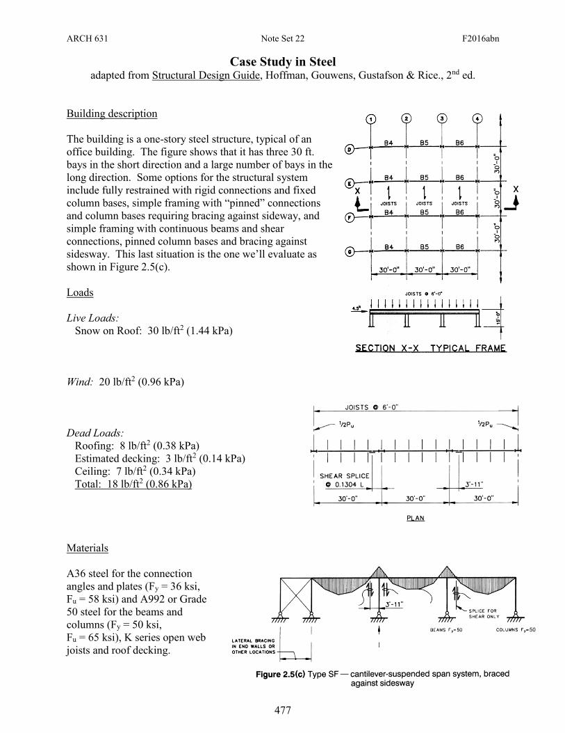
Building description
The building is a one-story steel structure, typical of an
office building. The figure shows that it has three 30 ft.
bays in the short direction and a large number of bays in the
long direction. Some options for the structural system
include fully restrained with rigid connections and fixed
column bases, simple framing with “pinned” connections
and column bases requiring bracing against sideway, and
simple framing with continuous beams and shear
connections, pinned column bases and bracing against
sidesway. This last situation is the one we’ll evaluate as
shown in Figure 2.5(c).
Loads
Live Loads:
Snow on Roof: 30 lb/ft2 (1.44 kPa)
Wind: 20 lb/ft2 (0.96 kPa)
Dead Loads:
Roofing: 8 lb/ft2 (0.38 kPa)
Estimated decking: 3 lb/ft2 (0.14 kPa)
Ceiling: 7 lb/ft2 (0.34 kPa)
Total: 18 lb/ft2 (0.86 kPa)
Materials
A36 steel for the connection
angles and plates (Fy = 36 ksi,
Fu = 58 ksi) and A992 or Grade
50 steel for the beams and
columns (Fy = 50 ksi,
Fu = 65 ksi), K series open web
joists and roof decking.
50
Page 2
ARCH 631 Note Set 22 F2016abn
478
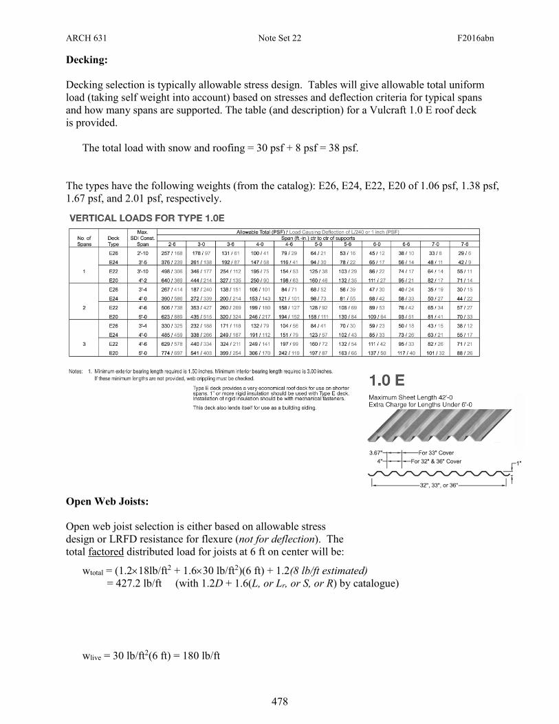
Decking:
Decking selection is typically allowable stress design. Tables will give allowable total uniform
load (taking self weight into account) based on stresses and deflection criteria for typical spans
and how many spans are supported. The table (and description) for a Vulcraft 1.0 E roof deck
is provided.
The total load with snow and roofing = 30 psf + 8 psf = 38 psf.
The types have the following weights (from the catalog): E26, E24, E22, E20 of 1.06 psf, 1.38 psf,
1.67 psf, and 2.01 psf, respectively.
Open Web Joists:
Open web joist selection is either based on allowable stress
design or LRFD resistance for flexure (not for deflection). The
total factored distributed load for joists at 6 ft on center will be:
wtotal = (1.218lb/ft2 + 1.630 lb/ft2)(6 ft) + 1.2(8 lb/ft estimated)
= 427.2 lb/ft (with 1.2D + 1.6(L, or Lr, or S, or R) by catalogue)
wlive = 30 lb/ft2(6 ft) = 180 lb/ft
Page 3
ARCH 631 Note Set 22 F2016abn
479
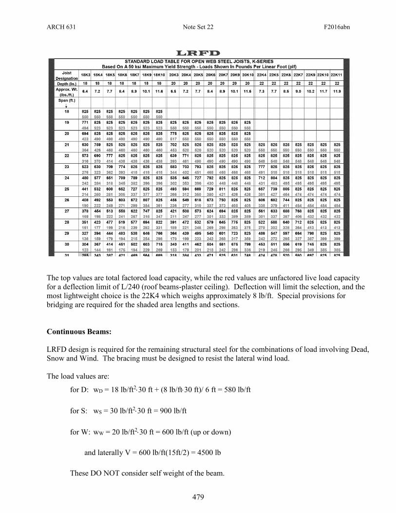
The top values are total factored load capacity, while the red values are unfactored live load capacity
for a deflection limit of L/240 (roof beams-plaster ceiling). Deflection will limit the selection, and the
most lightweight choice is the 22K4 which weighs approximately 8 lb/ft. Special provisions for
bridging are required for the shaded area lengths and sections.
Continuous Beams:
LRFD design is required for the remaining structural steel for the combinations of load involving Dead,
Snow and Wind. The bracing must be designed to resist the lateral wind load.
The load values are:
for D: wD = 18 lb/ft230 ft + (8 lb/ft30 ft)/ 6 ft = 580 lb/ft
for S: wS = 30 lb/ft230 ft = 900 lb/ft
for W: wW = 20 lb/ft230 ft = 600 lb/ft (up or down)
and laterally V = 600 lb/ft(15ft/2) = 4500 lb
These DO NOT consider self weight of the beam.
Page 4
ARCH 631 Note Set 22 F2016abn
480
The applicable combinations for the tributary width of 30 ft. are:
1.4D wu = 1.4(580 lb/ft) = 812 lb/ft
1.2D + 1.6L + 0.5(Lr or S or R)
wu = 1.2(580 lb/ft) + 0.5(900 lb/ft) = 1146 lb/ft
1.2D + 1.6(Lr or S or R) + (L or 0.5W)
wu = 1.2(580 lb/ft) + 1.6(900 lb/ft) + 0.5(600 lb/ft) = 2436 lb/ft
1.2D + 1.0W + L + 0.5(Lr or S or R)
wu = 1.2(580 lb/ft) + 1.0(600 lb/ft) + 0.5(900 lb/ft) = 1746 lb/ft
1.2D + 1.0E + L + 0.25S
wu = 1.2(580 lb/ft) + 0.25(900 lb/ft) = 921 lb/ft
0.9D + 1.0W wu = 0.9(580 lb/ft) + 1.0(-600 lb/ft) [uplift] = -78 lb/ft (up)
L, R, Lr , & E & don’t exist for our case.
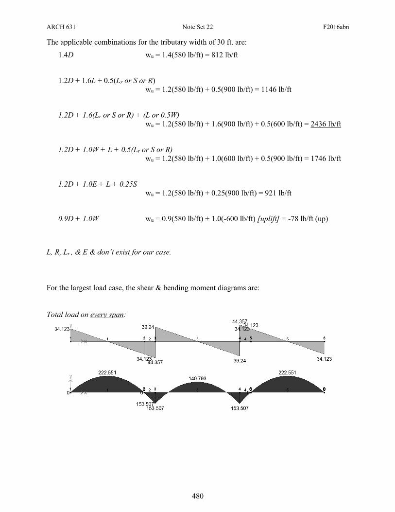
For the largest load case, the shear & bending moment diagrams are:
Total load on every span:
Page 5
ARCH 631 Note Set 22 F2016abn
481
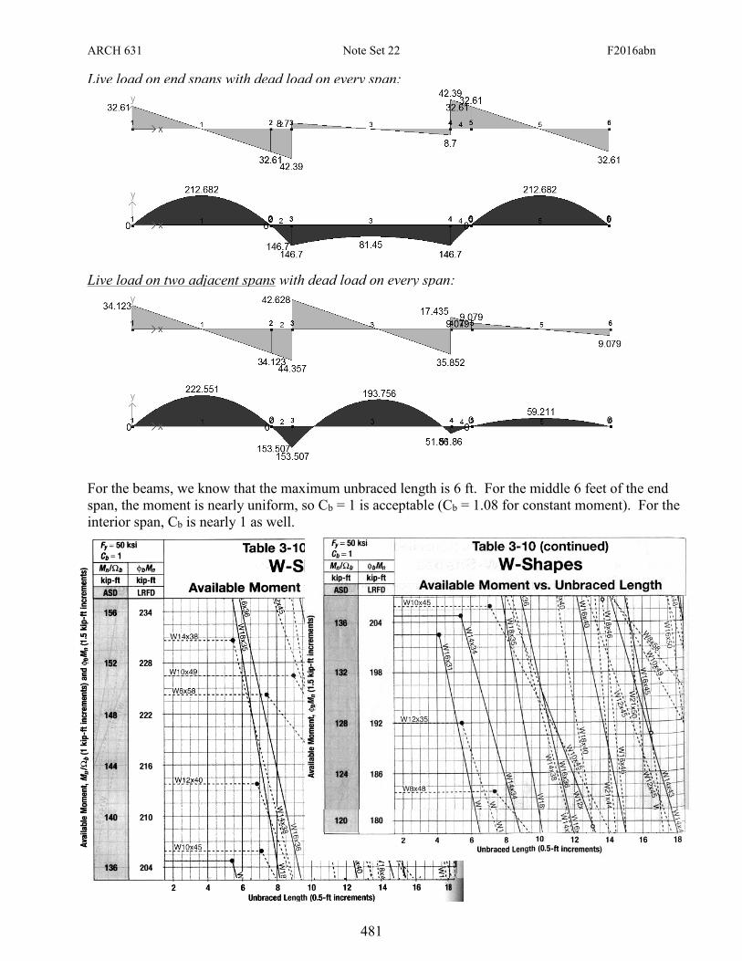
Live load on end spans with dead load on every span:
Live load on two adjacent spans with dead load on every span:
For the beams, we know that the maximum unbraced length is 6 ft. For the middle 6 feet of the end
span, the moment is nearly uniform, so Cb = 1 is acceptable (Cb = 1.08 for constant moment). For the
interior span, Cb is nearly 1 as well.
Page 6
ARCH 631 Note Set 22 F2016abn
482
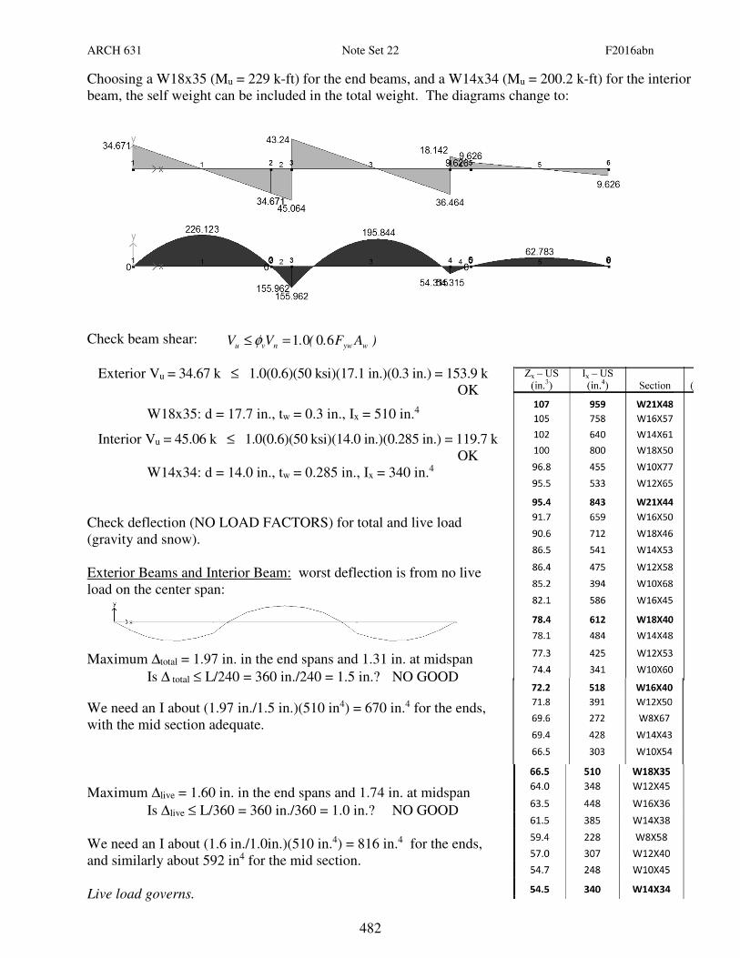
Choosing a W18x35 (Mu = 229 k-ft) for the end beams, and a W14x34 (Mu = 200.2 k-ft) for the interior
beam, the self weight can be included in the total weight. The diagrams change to:
Check beam shear:
Exterior Vu = 34.67 k ≤ 1.0(0.6)(50 ksi)(17.1 in.)(0.3 in.) = 153.9 k
OK
W18x35: d = 17.7 in., tw = 0.3 in., Ix = 510 in.4
Interior Vu = 45.06 k ≤ 1.0(0.6)(50 ksi)(14.0 in.)(0.285 in.) = 119.7 k
OK
W14x34: d = 14.0 in., tw = 0.285 in., Ix = 340 in.4
Check deflection (NO LOAD FACTORS) for total and live load
(gravity and snow).
Exterior Beams and Interior Beam: worst deflection is from no live
load on the center span:
Maximum ∆total = 1.97 in. in the end spans and 1.31 in. at midspan
Is ∆ total ≤ L/240 = 360 in./240 = 1.5 in.? NO GOOD
We need an I about (1.97 in./1.5 in.)(510 in4) = 670 in.4 for the ends,
with the mid section adequate.
Maximum ∆live = 1.60 in. in the end spans and 1.74 in. at midspan
Is ∆live ≤ L/360 = 360 in./360 = 1.0 in.? NO GOOD
We need an I about (1.6 in./1.0in.)(510 in.4) = 816 in.4 for the ends,
and similarly about 592 in4 for the mid section.
Live load governs.
)AF.(.VV wywnvu 6001=≤ φ
Page 7
ARCH 631 Note Set 22 F2016abn
483
The W21x44 is the most economical out of the sections for the ends, shown with bold type in the
group, with Ix = 843 in.4
The W18x40 is the most economical out of the sections for the ends, shown with bold type in the
group, with Ix = 612 in.4
Now, live = 0.964 in., which is less than allowable.
Columns:
The load in the interior columns: Pu = 88.5 k (sum of the shears).
This column will see minimal eccentricity from the difference in
shear and half the column depth as the moment arm.
The load in the exterior columns: Pu = 34.8 k. These columns will
see some eccentricity from the beam shear connections. We can
determine this by using half the column depth as the eccentricity
distance.
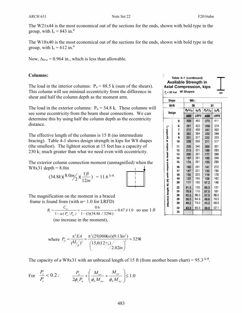
The effective length of the columns is 15 ft (no intermediate
bracing). Table 4-1 shows design strength in kips for W8 shapes
(the smallest). The lightest section at 15 feet has a capacity of
230 k; much greater than what we need even with eccentricity.
The exterior column connection moment (unmagnified) when the
W8x31 depth = 8.0in
18 0(34 8 )( )( )
2 12
ft. in. kin
= 11.6 k-ft.
The magnification on the moment in a braced
frame is found from (with α= 1.0 for LRFD)
1
1
0 60 67 1 0
1 1 (1)(34 8 329 )
m
u e
C .B . .
( P P ) . k / k
so use 1.0
(no increase in the moment),
where k
inft
inksi
rkL
EAP
ftin
e329
02.2)12(15
)13.9)(000,29(
)(2
22
2
2
1
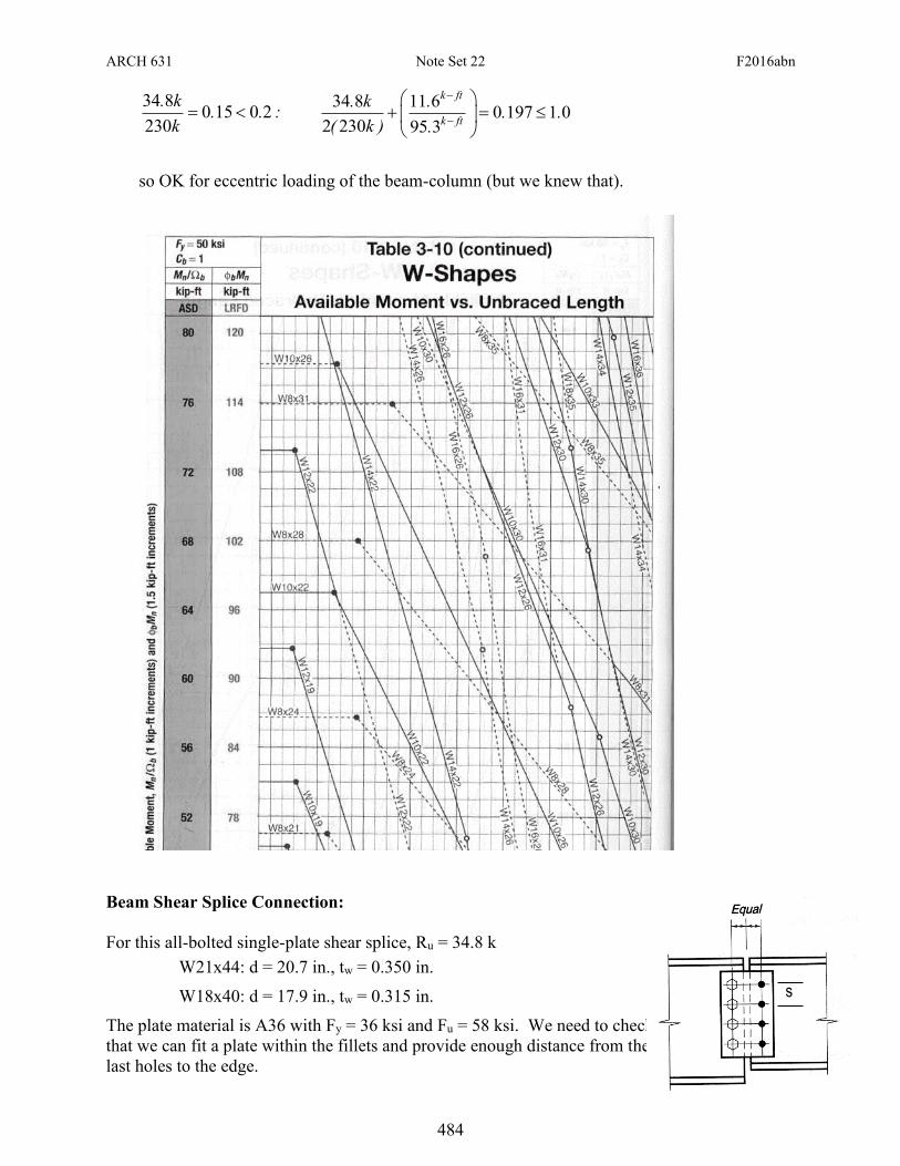
The capacity of a W8x31 with an unbraced length of 15 ft (from another beam chart) = 95.3 k-ft.
For :.P
P
c
r 20 0.12
nyb
uy
nxb
ux
nc
u
M
M
M
M
P
P
Page 8
ARCH 631 Note Set 22 F2016abn
484
34 8
0 15 0 2230
. k. . :
k
34 8 11 60 197 1 0
2 230 95 3
k ft
k ft
. k .. .
( k ) .
so OK for eccentric loading of the beam-column (but we knew that).
Beam Shear Splice Connection:
For this all-bolted single-plate shear splice, Ru = 34.8 k
W21x44: d = 20.7 in., tw = 0.350 in.
W18x40: d = 17.9 in., tw = 0.315 in.
The plate material is A36 with Fy = 36 ksi and Fu = 58 ksi. We need to check
that we can fit a plate within the fillets and provide enough distance from the
last holes to the edge.
s
Page 9
ARCH 631 Note Set 22 F2016abn
485
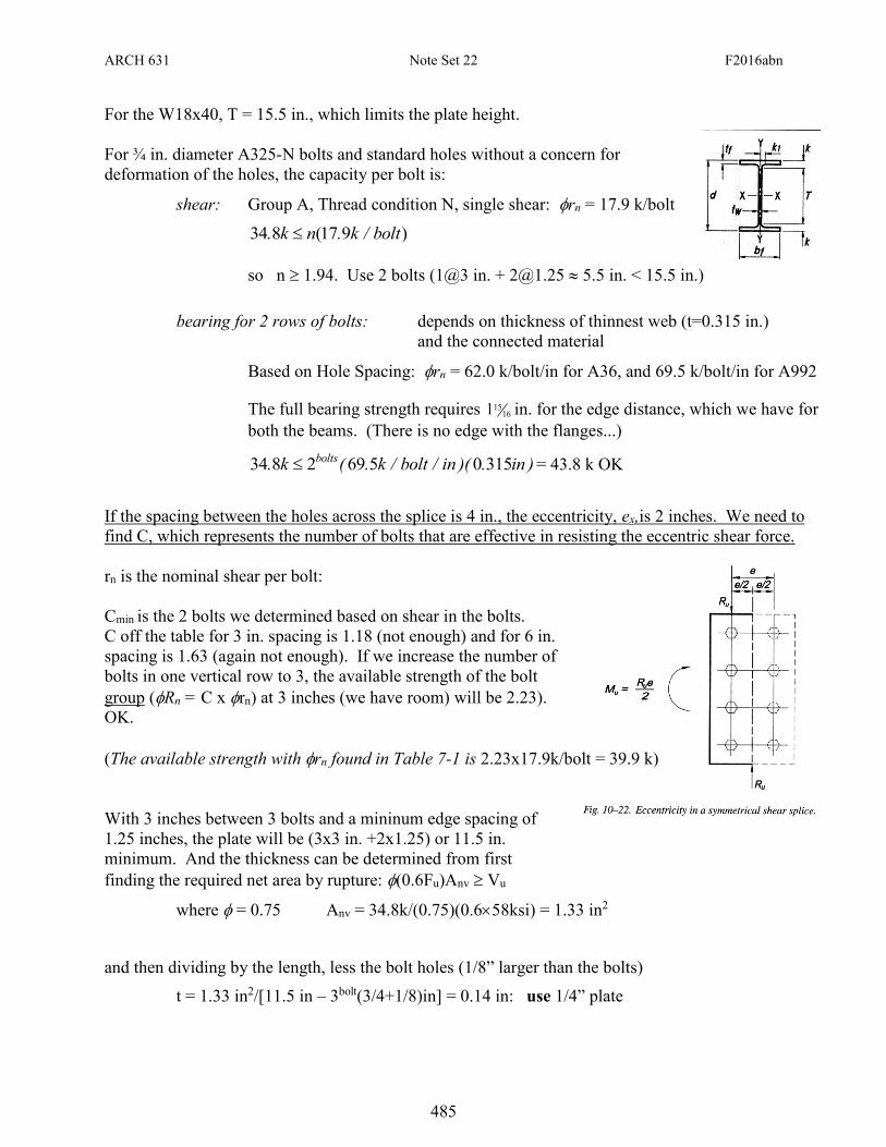
For the W18x40, T = 15.5 in., which limits the plate height.
For ¾ in. diameter A325-N bolts and standard holes without a concern for
deformation of the holes, the capacity per bolt is:
shear: Group A, Thread condition N, single shear: rn = 17.9 k/bolt
34 8 (17 9 ). k n . k / bolt
so n 1.94. Use 2 bolts (1@3 in. + [email protected] 5.5 in. < 15.5 in.)
bearing for 2 rows of bolts: depends on thickness of thinnest web (t=0.315 in.)
and the connected material
Based on Hole Spacing: rn = 62.0 k/bolt/in for A36, and 69.5 k/bolt/in for A992
The full bearing strength requires 16151 in. for the edge distance, which we have for
both the beams. (There is no edge with the flanges...)
34 8 2 69 5 0 315bolts. k ( . k / bolt / in )( . in ) = 43.8 k OK
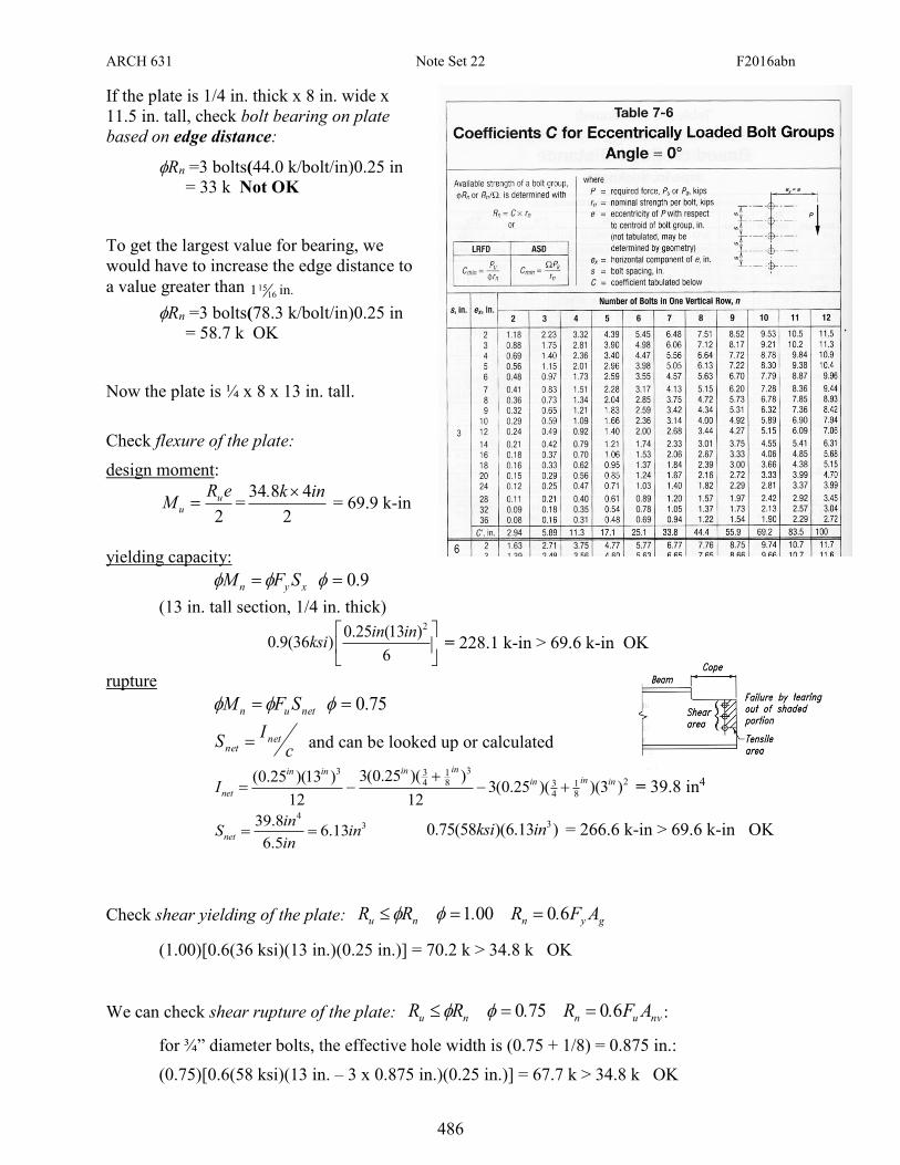
If the spacing between the holes across the splice is 4 in., the eccentricity, ex,is 2 inches. We need to
find C, which represents the number of bolts that are effective in resisting the eccentric shear force.
rn is the nominal shear per bolt:
Cmin is the 2 bolts we determined based on shear in the bolts.
C off the table for 3 in. spacing is 1.18 (not enough) and for 6 in.
spacing is 1.63 (again not enough). If we increase the number of
bolts in one vertical row to 3, the available strength of the bolt
group (Rn = C x rn) at 3 inches (we have room) will be 2.23).
OK.
(The available strength with rn found in Table 7-1 is 2.23x17.9k/bolt = 39.9 k)
With 3 inches between 3 bolts and a mininum edge spacing of
1.25 inches, the plate will be (3x3 in. +2x1.25) or 11.5 in.
minimum. And the thickness can be determined from first
finding the required net area by rupture: (0.6Fu)Anv Vu
where = 0.75 Anv = 34.8k/(0.75)(0.658ksi) = 1.33 in2
and then dividing by the length, less the bolt holes (1/8” larger than the bolts)
t = 1.33 in2/[11.5 in – 3bolt(3/4+1/8)in] = 0.14 in: use 1/4” plate
Page 10
ARCH 631 Note Set 22 F2016abn
486
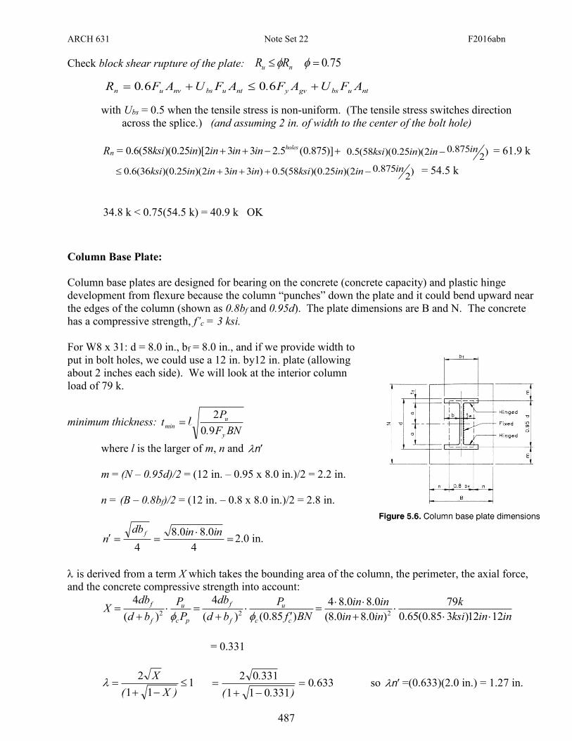
If the plate is 1/4 in. thick x 8 in. wide x
11.5 in. tall, check bolt bearing on plate
based on edge distance:
Rn =3 bolts(44.0 k/bolt/in)0.25 in
= 33 k Not OK
To get the largest value for bearing, we
would have to increase the edge distance to
a value greater than 15161 in.
Rn =3 bolts(78.3 k/bolt/in)0.25 in
= 58.7 k OK
Now the plate is ¼ x 8 x 13 in. tall.
Check flexure of the plate:
design moment:
2
eRM u
u =34 8 4
2
. k in = 69.9 k-in
yielding capacity:
9.0 xyn SFM
(13 in. tall section, 1/4 in. thick)
20.25 (13 )
0.9(36 )6
in inksi
= 228.1 k-in > 69.6 k-in OK
rupture
75.0 netun SFM
c
IS net
net and can be looked up or calculated
33 3 1
24 8 3 14 8
3(0.25 )( )(0.25 )(13 )3(0.25 )( )(3 )
12 12
ininin ininin in
netI
= 39.8 in4
4
339.86.13
6.5net
inS in
in 30.75(58 )(6.13 )ksi in = 266.6 k-in > 69.6 k-in OK
Check shear yielding of the plate: gynnu AF.R.RR 60001
(1.00)[0.6(36 ksi)(13 in.)(0.25 in.)] = 70.2 k > 34.8 k OK
We can check shear rupture of the plate: nvunnu AF.R.RR 60750 :
for ¾” diameter bolts, the effective hole width is (0.75 + 1/8) = 0.875 in.:
(0.75)[0.6(58 ksi)(13 in. – 3 x 0.875 in.)(0.25 in.)] = 67.7 k > 34.8 k OK
6
Page 11
ARCH 631 Note Set 22 F2016abn
487
Check block shear rupture of the plate: 750.RR nu
with Ubs = 0.5 when the tensile stress is non-uniform. (The tensile stress switches direction
across the splice.) (and assuming 2 in. of width to the center of the bolt hole)
Rn = 0.6(58 )(0.25 )[2 3 3 2.5 (0.875)]holesksi in in in in 0.8750.5(58 )(0.25 )(2 )2
inksi in in = 61.9 k
0.8750.6(36 )(0.25 )(2 3 3 ) 0.5(58 )(0.25 )(2 )2
inksi in in in in ksi in in = 54.5 k
34.8 k < 0.75(54.5 k) = 40.9 k OK
Column Base Plate:
Column base plates are designed for bearing on the concrete (concrete capacity) and plastic hinge
development from flexure because the column “punches” down the plate and it could bend upward near
the edges of the column (shown as 0.8bf and 0.95d). The plate dimensions are B and N. The concrete
has a compressive strength, f’c = 3 ksi.
For W8 x 31: d = 8.0 in., bf = 8.0 in., and if we provide width to
put in bolt holes, we could use a 12 in. by12 in. plate (allowing
about 2 inches each side). We will look at the interior column
load of 79 k.
minimum thickness: BNF.
Pt
y
umin
90
2l
where l is the larger of m, n and n
m = (N – 0.95d)/2 = (12 in. – 0.95 x 8.0 in.)/2 = 2.2 in.
n = (B – 0.8bf)/2 = (12 in. – 0.8 x 8.0 in.)/2 = 2.8 in.
4
0.80.8
4
inindbn
f2.0 in.
is derived from a term X which takes the bounding area of the column, the perimeter, the axial force,
and the concrete compressive strength into account:
2 2 2
4 4 4 8.0 8.0 79
(0.85 ) 0.65(0.85 3 )12 12( ) ( ) (8.0 8.0 )
f fu u
c p c cf f
db dbP P in in kX
P f BN ksi in ind b d b in in
= 0.331
111
2
)X(
X 6330
331011
33102.
).(
.
so n =(0.633)(2.0 in.) = 1.27 in.
ntubsgvyntubsnvun AFUAF.AFUAF.R 6060
Page 12
ARCH 631 Note Set 22 F2016abn
488
therefor: l = 2.8 in.:
)in)(in)(ksi(.
k)in.(
BNF.
Pt
y
up
12123690
79282
90
2 l = 0.515 in.
Use a 5/8 in. thick plate.
The anchor bolts must also be able to resist lateral shear. There also is friction between the steel and
concrete to help. The International Building Code provided specifications for minimum edge distances
and anchorage.
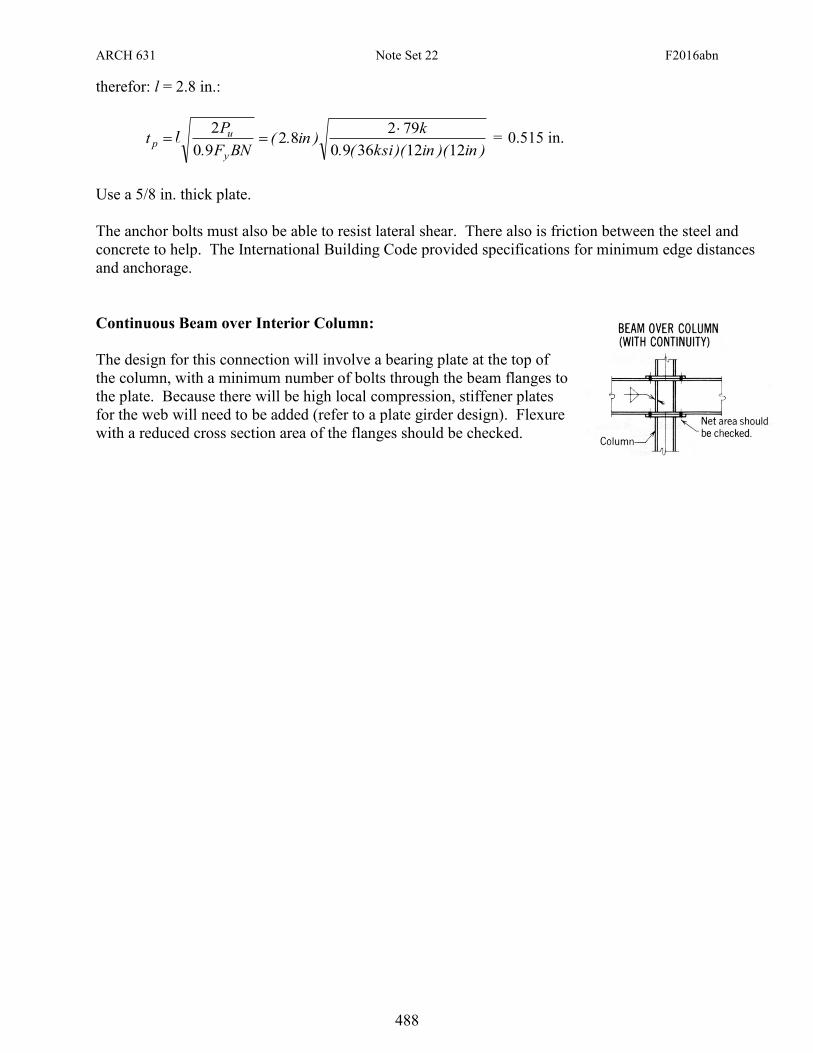
Continuous Beam over Interior Column:
The design for this connection will involve a bearing plate at the top of
the column, with a minimum number of bolts through the beam flanges to
the plate. Because there will be high local compression, stiffener plates
for the web will need to be added (refer to a plate girder design). Flexure
with a reduced cross section area of the flanges should be checked.