Case Study IP Telephony Deployment: Australian Catholic University Document ID: 13913 Contents Introduction AARNet AARNet Topology Quality of Service Gateways Dial Plans Gatekeeper ACU IP Telephony Network ACU Network Topology QoS in the Campus QoS in the RNO Gateways Dial Plan Cisco CallManager Voice Mail Media Resources Fax and Modem Support Software Versions Related Information Introduction The Australian Academic and Research Network (AARNet) is a nationwide high-speed IP network that interconnects 37 Australian universities as well as the Commonwealth Scientific and Industrial Research Organization (CSIRO). AARNet was initially built as a data network, but it has carried Voice over IP (VoIP) since early 2000. The VoIP network currently deployed is a toll-bypass solution that carries VoIP calls between the universities and the CSIRO private automatic branch exchanges (PABXs). It also provides public switched telephone network (PSTN) gateways that allow PSTN to hop off at the most cost-effective point. For example, a call from a PABX phone in Melbourne to a PSTN phone in Sydney is carried as VoIP from Melbourne to the Sydney PSTN gateway. It is there connected to the PSTN. Australian Catholic University (ACU) is one of the universities that connects to AARNet. In late 2000, ACU began an IP Telephony deployment that deployed approximately 2,000 IP phones across six university campuses. This case study covers the ACU IP Telephony deployment. The project is completed. However, there are significant architectural issues to address in the AARNet backbone if the network is to scale when other universities follow in the footsteps of ACU. This document describes these issues and proposes and discusses various solutions. The ACU IP Telephony deployment is likely to be adjusted later in order to fall in line with the final recommended architecture. Note: Deakin University was the first Australian university to deploy IP Telephony. However, Deakin University does not use AARNet to carry IP Telephony traffic.
Transcript
Case Study IP Telephony Deployment: AustralianCatholic University
Document ID: 13913
Contents
Introduction AARNet AARNet Topology Quality of Service Gateways Dial Plans Gatekeeper ACU IP Telephony Network ACU Network Topology QoS in the Campus QoS in the RNO Gateways Dial Plan Cisco CallManager Voice Mail Media Resources Fax and Modem Support Software Versions Related Information
Introduction
The Australian Academic and Research Network (AARNet) is a nationwide high−speed IP network thatinterconnects 37 Australian universities as well as the Commonwealth Scientific and Industrial ResearchOrganization (CSIRO).
AARNet was initially built as a data network, but it has carried Voice over IP (VoIP) since early 2000. TheVoIP network currently deployed is a toll−bypass solution that carries VoIP calls between the universities andthe CSIRO private automatic branch exchanges (PABXs). It also provides public switched telephone network(PSTN) gateways that allow PSTN to hop off at the most cost−effective point. For example, a call from aPABX phone in Melbourne to a PSTN phone in Sydney is carried as VoIP from Melbourne to the SydneyPSTN gateway. It is there connected to the PSTN.
Australian Catholic University (ACU) is one of the universities that connects to AARNet. In late 2000, ACUbegan an IP Telephony deployment that deployed approximately 2,000 IP phones across six universitycampuses.
This case study covers the ACU IP Telephony deployment. The project is completed. However, there aresignificant architectural issues to address in the AARNet backbone if the network is to scale when otheruniversities follow in the footsteps of ACU. This document describes these issues and proposes and discussesvarious solutions. The ACU IP Telephony deployment is likely to be adjusted later in order to fall in line withthe final recommended architecture.
Note: Deakin University was the first Australian university to deploy IP Telephony. However, DeakinUniversity does not use AARNet to carry IP Telephony traffic.
AARNet
The Australian universities and CSIRO built AARNet in 1990 through the Australian Vice−Chancellors'Committee (AVCC). Ninety−nine percent of Australian Internet traffic was to the founding members duringthe first few years. A small amount of commercial traffic was from organizations that had a close associationwith the tertiary and research sector. Use by the non−AARNet userbase increased to 20 percent of the totaltraffic by late 1994.
The AVCC sold the commercial customer base of AARNet to Telstra in July of 1995. This event spawnedwhat was eventually to become Telstra BigPond. This stimulated further growth of the commercial andprivate use of the Internet in Australia. The transfer of intellectual property and expertise resulted in thedevelopment of the Internet in Australia. Otherwise, this would not have occurred at such a rapid rate.
The AVCC developed AARNet2 in early 1997. It was a further refinement of the Internet in Australia, whichemploys high−bandwidth ATM links and Internet services under a contract with Cable & Wireless Optus(CWO) Limited. The rapid deployment of IP services by CWO to meet the AARNet2 requirements was due inpart to the transfer of knowledge and expertise from AARNet.
ACU
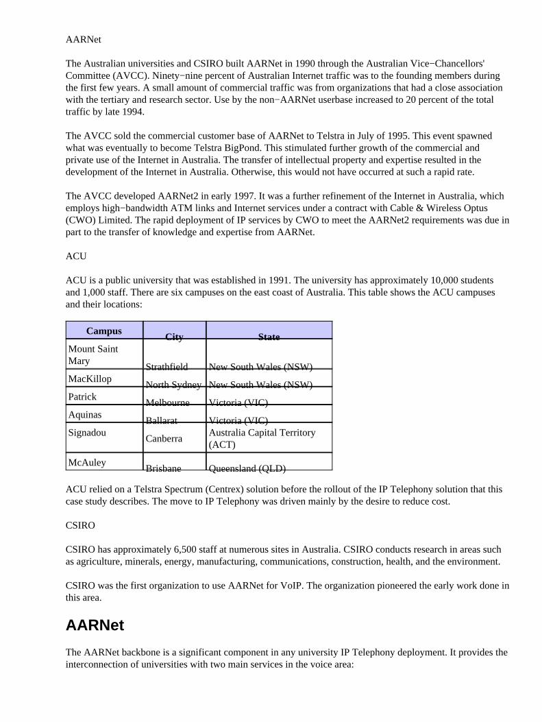
ACU is a public university that was established in 1991. The university has approximately 10,000 studentsand 1,000 staff. There are six campuses on the east coast of Australia. This table shows the ACU campusesand their locations:
CampusCity State
Mount SaintMary
Strathfield New South Wales (NSW)MacKillop
North Sydney New South Wales (NSW)Patrick
Melbourne Victoria (VIC)Aquinas
Ballarat Victoria (VIC)Signadou
CanberraAustralia Capital Territory(ACT)
McAuleyBrisbane Queensland (QLD)
ACU relied on a Telstra Spectrum (Centrex) solution before the rollout of the IP Telephony solution that thiscase study describes. The move to IP Telephony was driven mainly by the desire to reduce cost.
CSIRO
CSIRO has approximately 6,500 staff at numerous sites in Australia. CSIRO conducts research in areas suchas agriculture, minerals, energy, manufacturing, communications, construction, health, and the environment.
CSIRO was the first organization to use AARNet for VoIP. The organization pioneered the early work done inthis area.
AARNet
The AARNet backbone is a significant component in any university IP Telephony deployment. It provides theinterconnection of universities with two main services in the voice area:
Transport of VoIP Realtime Transport Protocol (RTP) packets with the guarantee of Quality ofService (QoS) appropriate to voice
•
Low−cost hopoff point to the PSTNs around the country•
This section describes the current AARNet architecture and how it delivers these services. It also outlinessome of the scalability issues that arise as more universities deploy the IP Telephony solution. Finally, itdiscusses the possible solutions for these scalability issues.
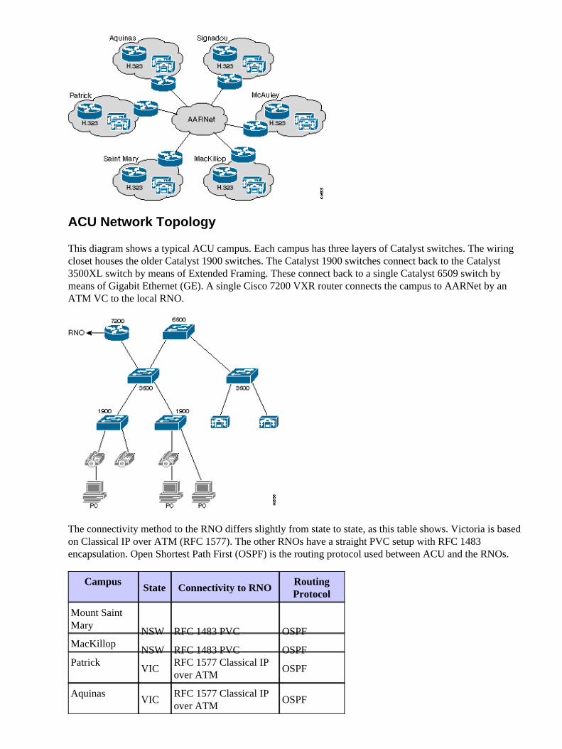
AARNet Topology
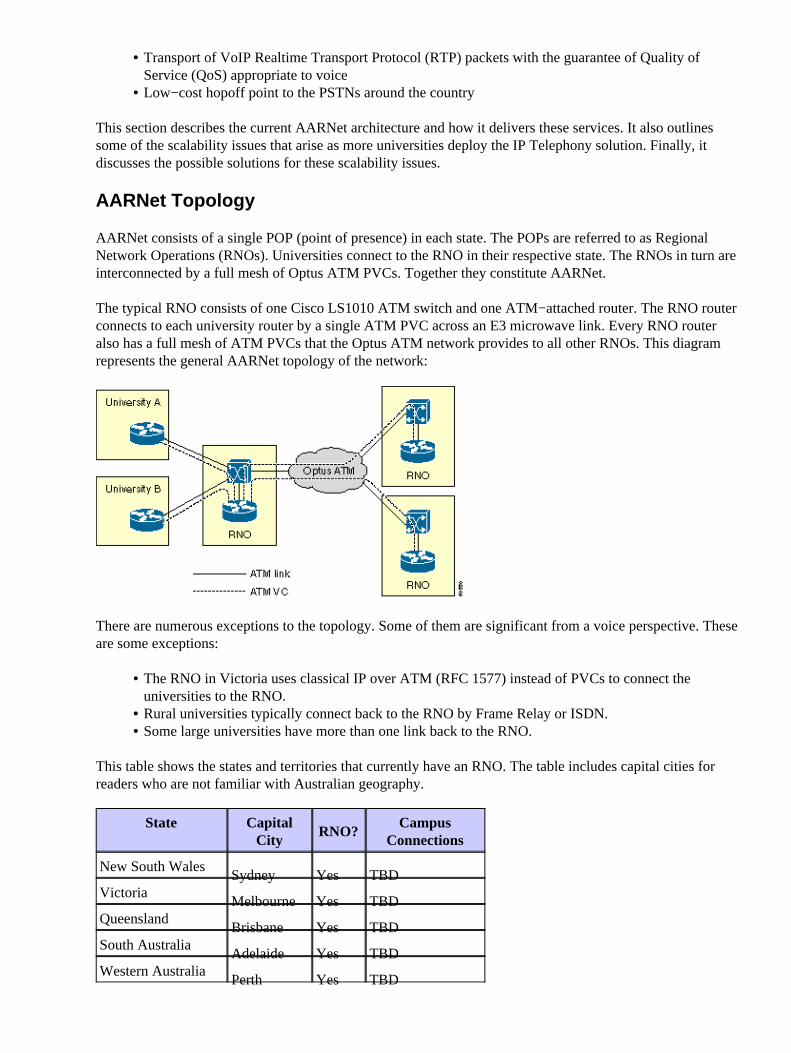
AARNet consists of a single POP (point of presence) in each state. The POPs are referred to as RegionalNetwork Operations (RNOs). Universities connect to the RNO in their respective state. The RNOs in turn areinterconnected by a full mesh of Optus ATM PVCs. Together they constitute AARNet.
The typical RNO consists of one Cisco LS1010 ATM switch and one ATM−attached router. The RNO routerconnects to each university router by a single ATM PVC across an E3 microwave link. Every RNO routeralso has a full mesh of ATM PVCs that the Optus ATM network provides to all other RNOs. This diagramrepresents the general AARNet topology of the network:
There are numerous exceptions to the topology. Some of them are significant from a voice perspective. Theseare some exceptions:
The RNO in Victoria uses classical IP over ATM (RFC 1577) instead of PVCs to connect theuniversities to the RNO.
•
Rural universities typically connect back to the RNO by Frame Relay or ISDN.• Some large universities have more than one link back to the RNO.•
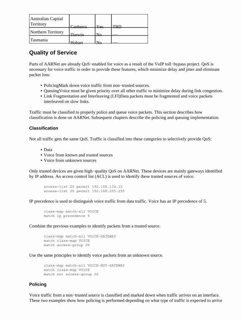
This table shows the states and territories that currently have an RNO. The table includes capital cities forreaders who are not familiar with Australian geography.
State CapitalCity
RNO?Campus
Connections
New South WalesSydney Yes TBD
VictoriaMelbourne Yes TBD
QueenslandBrisbane Yes TBD
South AustraliaAdelaide Yes TBD
Western AustraliaPerth Yes TBD
Australian CapitalTerritory
Canberra Yes TBDNorthern Territory
Darwin No −−Tasmania
Hobart No −−
Quality of Service
Parts of AARNet are already QoS−enabled for voice as a result of the VoIP toll−bypass project. QoS isnecessary for voice traffic in order to provide these features, which minimize delay and jitter and eliminatepacket loss:
Policing�Mark down voice traffic from non−trusted sources.• Queuing�Voice must be given priority over all other traffic to minimize delay during link congestion.• Link Fragmentation and Interleaving (LFI)�Data packets must be fragmented and voice packetsinterleaved on slow links.
•
Traffic must be classified to properly police and queue voice packets. This section describes howclassification is done on AARNet. Subsequent chapters describe the policing and queuing implementation.
Classification
Not all traffic gets the same QoS. Traffic is classified into these categories to selectively provide QoS:
Data• Voice from known and trusted sources• Voice from unknown sources•
Only trusted devices are given high−quality QoS on AARNet. These devices are mainly gateways identifiedby IP address. An access control list (ACL) is used to identify these trusted sources of voice.
Use the same principles to identify voice packets from an unknown source.
class−map match−all VOICE−NOT−GATEWAYmatch class−map VOICEmatch not access−group 20
Policing
Voice traffic from a non−trusted source is classified and marked down when traffic arrives on an interface.These two examples show how policing is performed depending on what type of traffic is expected to arrive
on a given interface:
The router looks for non−trusted voice packets and changes their IP precedence to 0 if there are trusted voicesources downstream.
policy−map INPUT−VOICEclass VOICE−NOT−GATEWAYset ip precedence 0
The router looks for all voice packets and changes their IP precedence to 0 if there are no known voicesources downstream.
policy−map INPUT−DATAclass VOICEset ip precedence 0
interface FastEthernet2/0/1description No downstream voice gatewaysservice−policy input INPUT−DATA
Non−voice Queuing
All VoIP in AARNet was toll−bypass until recently. This condition results in relatively few VoIP endpoints.The current queuing design distinguishes between interfaces that have VoIP devices downstream andinterfaces that do not. This section discusses queuing on non−VoIP interfaces.
A non−voice interface is configured for either weighted fair queuing (WFQ) or Weighted Random EarlyDetection (WRED). These can be configured directly on the interface. However, the queuing mechanism isapplied by means of a policy map in order to make it easy to change the queuing mechanism on a giveninterface type. There is one policy map per interface type. This reflects the fact that not all queuingmechanisms are supported on all interfaces.
The policy maps are attached to the respective interfaces and are specific to interface types. For example, thissimplifies the process of changing the queuing mechanism on Versatile Interface Processor−based(VIP−based) Ethernet ports from WRED to WFQ. It requires a single change in the policy map. The changesare made to all VIP−based Ethernet interfaces.
Any interface that has downstream−trusted VoIP devices is configured for Low Latency Queuing (LLQ). Anypacket that makes it through the incoming interface classification and retains a precedence of 5 is subject toLLQ. Any other packet is subject to either WFQ or WRED. This depends on the interface type.
Separate policy maps are created for each interface type in order to make QoS easier to administer. This issimilar to the non−voice queuing design. However, multiple policy maps exist for each interface type. This isbecause the capacity of the interface types for carrying voice traffic varies depending on link speed, PVCsettings, and so on. The number in the policy map name reflects the number of calls catered for 30 calls, 60calls, and so on.
The policy maps are attached to the respective interfaces. In this example, the policy map is specific to aninterface type. Currently no special treatment is given to voice signaling. The policy maps can easily beamended in one place if this becomes a requirement at a later stage on a given interface type. The changetakes affect for all interfaces of that type.
The queuing mechanism has some scalability issues. The main issue is that it relies on knowing the IP addressof every trusted VoIP device in the network. This was a reasonable limitation in the past when there was alimited number of VoIP gateways handling toll−bypass. The number of VoIP endpoints dramaticallyincreases, and it becomes more and more impractical with the deployment of IP Telephony. The ACLsbecome too long and too hard to manage.
The ACLs have been appended to trust traffic from a specific voice IP subnetwork at each ACU campus in thecase of ACU. This is an interim solution. These longer−term solutions are being investigated:
H.323 proxy• QoS ingress policing•
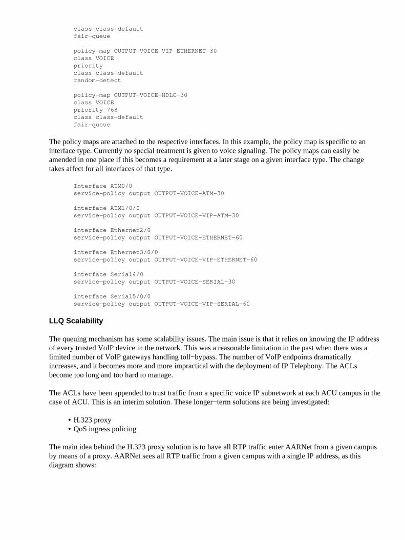
The main idea behind the H.323 proxy solution is to have all RTP traffic enter AARNet from a given campusby means of a proxy. AARNet sees all RTP traffic from a given campus with a single IP address, as thisdiagram shows:
The number of entries in the QoS ACLs is limited to one line per campus if this scheme is deployedconsistently. This scheme still has the potential to add up to 100 or more entries since there are 37 universitieswith multiple campuses. This too is not scalable. It might be necessary to move to a design with a single orlimited number of shared super−proxies at each RNO. This reduces the number of trusted IP addresses to six.However, this opens up a QoS policing issue on the path from the campus to the proxy at the RNO.
Note: Cisco CallManager intercluster trunks do not currently work through an H.323 proxy because theintercluster signaling is not native H.225.
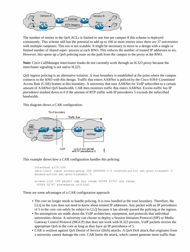
QoS ingress policing is an alternative solution. A trust boundary is established at the point where the campusconnects to the RNO with this design. Traffic that enters AARNet is policed by the Cisco IOS® CommittedAccess Rate (CAR) feature at this boundary. A university that uses AARNet for VoIP subscribes to a certainamount of AARNet QoS bandwidth. CAR then monitors traffic that enters AARNet. Excess traffic has IPprecedence marked down to 0 if the amount of RTP traffic with IP precedence 5 exceeds the subscribedbandwidth.
This diagram shows a CAR configuration:
This example shows how a CAR configuration handles this policing:
access−list 100 permit udp any range 16384 32767 any range 16384 32767 precedence critical
These are some advantages of a CAR configuration approach:
The core no longer needs to handle policing. It is now handled at the trust boundary. Therefore, theLLQ in the core does not need to know about trusted IP addresses. Any packet with an IP precedenceof 5 in the core can safely be subject to LLQ because it has already passed the policing at the ingress.
•
No assumptions are made about the VoIP architecture, equipment, and protocols that individualuniversities choose. A university can choose to deploy a Session Initiation Protocol (SIP) or MediaGateway Control Protocol (MGCP) that does not work with H.323 proxies. VoIP packets receive theappropriate QoS in the core as long as they have an IP precedence of 5.
•
CAR is resilient against QoS Denial of Service (DoS) attacks. A QoS DoS attack that originates froma university cannot damage the core. CAR limits the attack, which cannot generate more traffic than
•
what is present when the maximum number of allowed VoIP calls is active.
VoIP calls to or from that campus can suffer during an attack. However, it is up to the individualuniversity to protect itself internally. The university can tighten the CAR ACLs on the router so thatall but selected VoIP subnetworks have the IP precedence marked down.
Each campus has an internal trust boundary at the point where users connect to the campus LAN inthe ultimate design. Traffic with an IP precedence of 5 that this trust boundary receives is limited to160 kbps per switch port, or two G.711 VoIP calls. Traffic in excess of this rate is marked down.Implementation of this scheme requires Catalyst 6500 switches or something similar with ratelimiting functionality.Bandwidth provisioning in the core simplifies as each university subscribes to a fixed amount of QoSbandwidth. This also makes QoS billing simple because each university can pay a flat monthly feebased on a QoS bandwidth subscription.
•
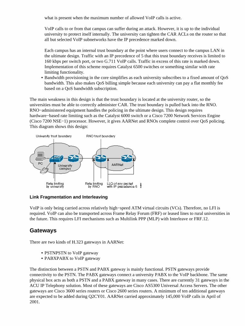
The main weakness in this design is that the trust boundary is located at the university router, so theuniversities must be able to correctly administer CAR. The trust boundary is pulled back into the RNO.RNO−administered equipment handles the policing in the ultimate design. This design requireshardware−based rate limiting such as the Catalyst 6000 switch or a Cisco 7200 Network Services Engine(Cisco 7200 NSE−1) processor. However, it gives AARNet and RNOs complete control over QoS policing.This diagram shows this design:
Link Fragmentation and Interleaving
VoIP is only being carried across relatively high−speed ATM virtual circuits (VCs). Therefore, no LFI isrequired. VoIP can also be transported across Frame Relay Forum (FRF) or leased lines to rural universities inthe future. This requires LFI mechanisms such as Multilink PPP (MLP) with Interleave or FRF.12.
Gateways
There are two kinds of H.323 gateways in AARNet:
PSTN�PSTN to VoIP gateway• PABX�PABX to VoIP gateway•
The distinction between a PSTN and PABX gateway is mainly functional. PSTN gateways provideconnectivity to the PSTN. The PABX gateways connect a university PABX to the VoIP backbone. The samephysical box acts as both a PSTN and a PABX gateway in many cases. There are currently 31 gateways in theACU IP Telephony solution. Most of these gateways are Cisco AS5300 Universal Access Servers. The othergateways are Cisco 3600 series routers or Cisco 2600 series routers. A minimum of ten additional gatewaysare expected to be added during Q2CY01. AARNet carried approximately 145,000 VoIP calls in April of2001.
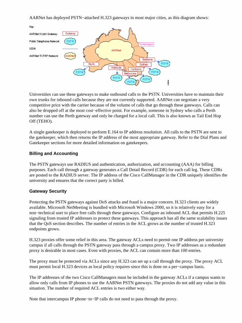
AARNet has deployed PSTN−attached H.323 gateways in most major cities, as this diagram shows:
Universities can use these gateways to make outbound calls to the PSTN. Universities have to maintain theirown trunks for inbound calls because they are not currently supported. AARNet can negotiate a verycompetitive price with the carrier because of the volume of calls that go through these gateways. Calls canalso be dropped off at the most cost−effective point. For example, someone in Sydney who calls a Perthnumber can use the Perth gateway and only be charged for a local call. This is also known as Tail End HopOff (TEHO).
A single gatekeeper is deployed to perform E.164 to IP address resolution. All calls to the PSTN are sent tothe gatekeeper, which then returns the IP address of the most appropriate gateway. Refer to the Dial Plans andGatekeeper sections for more detailed information on gatekeepers.
Billing and Accounting
The PSTN gateways use RADIUS and authentication, authorization, and accounting (AAA) for billingpurposes. Each call through a gateway generates a Call Detail Record (CDR) for each call leg. These CDRsare posted to the RADIUS server. The IP address of the Cisco CallManager in the CDR uniquely identifies theuniversity and ensures that the correct party is billed.
Gateway Security
Protecting the PSTN gateways against DoS attacks and fraud is a major concern. H.323 clients are widelyavailable. Microsoft NetMeeting is bundled with Microsoft Windows 2000, so it is relatively easy for anon−technical user to place free calls through these gateways. Configure an inbound ACL that permits H.225signaling from trusted IP addresses to protect these gateways. This approach has all the same scalability issuesthat the QoS section describes. The number of entries in the ACL grows as the number of trusted H.323endpoints grows.
H.323 proxies offer some relief in this area. The gateway ACLs need to permit one IP address per universitycampus if all calls through the PSTN gateway pass through a campus proxy. Two IP addresses as a redundantproxy is desirable in most cases. Even with proxies, the ACL can contain more than 100 entries.
The proxy must be protected via ACLs since any H.323 can set up a call through the proxy. The proxy ACLmust permit local H.323 devices as local policy requires since this is done on a per−campus basis.
The IP addresses of the two Cisco CallManagers must be included in the gateway ACLs if a campus wants toallow only calls from IP phones to use the AARNet PSTN gateways. The proxies do not add any value in thissituation. The number of required ACL entries is two either way.
Note that intercampus IP phone−to−IP calls do not need to pass through the proxy.
Dial Plans
The current VoIP dial plan is straightforward. Users can place these two types of calls from a VoIP gatewayperspective:
Call a phone at a different campus but at the same university.• Call a PSTN phone or a phone at a different university.•
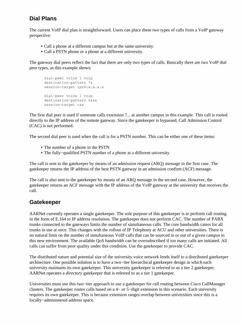
The gateway dial peers reflect the fact that there are only two types of calls. Basically there are two VoIP dialpeer types, as this example shows:
The first dial peer is used if someone calls extension 7... at another campus in this example. This call is routeddirectly to the IP address of the remote gateway. Since the gatekeeper is bypassed, Call Admission Control(CAC) is not performed.
The second dial peer is used when the call is for a PSTN number. This can be either one of these items:
The number of a phone in the PSTN• The fully−qualified PSTN number of a phone at a different university•
The call is sent to the gatekeeper by means of an admission request (ARQ) message in the first case. Thegatekeeper returns the IP address of the best PSTN gateway in an admission confirm (ACF) message.
The call is also sent to the gatekeeper by means of an ARQ message in the second case. However, thegatekeeper returns an ACF message with the IP address of the VoIP gateway at the university that receives thecall.
Gatekeeper
AARNet currently operates a single gatekeeper. The sole purpose of this gatekeeper is to perform call routingin the form of E.164 to IP address resolution. The gatekeeper does not perform CAC. The number of PABXtrunks connected to the gateways limits the number of simultaneous calls. The core bandwidth caters for alltrunks in use at once. This changes with the rollout of IP Telephony at ACU and other universities. There isno natural limit on the number of simultaneous VoIP calls that can be sourced in or out of a given campus inthis new environment. The available QoS bandwidth can be oversubscribed if too many calls are initiated. Allcalls can suffer from poor quality under this condition. Use the gatekeeper to provide CAC.
The distributed nature and potential size of the university voice network lends itself to a distributed gatekeeperarchitecture. One possible solution is to have a two−tier hierarchical gatekeeper design in which eachuniversity maintains its own gatekeeper. This university gatekeeper is referred to as a tier 2 gatekeeper.AARNet operates a directory gatekeeper that is referred to as a tier 1 gatekeeper.
Universities must use this two−tier approach to use a gatekeeper for call routing between Cisco CallManagerclusters. The gatekeeper routes calls based on a 4− or 5−digit extension in this scenario. Each universityrequires its own gatekeeper. This is because extension ranges overlap between universities since this is alocally−administered address space.
The university tier 2 gatekeepers perform CAC for calls to and from that university only. It also performsE.164 resolution for calls between only the campuses of that university. The call is routed by the tier 2gatekeeper to the tier 1 gatekeeper by means of a location request (LRQ) message if someone calls an IPphone at another university or calls the PSTN through an AARNet gateway. The LRQ is forwarded to the tier2 gatekeeper of that university if the call is for another university. This gatekeeper then returns an ACFmessage to the tier 2 gatekeeper at the university where the call originates. Both tier 2 gatekeepers performCAC. They only proceed with the call if there is sufficient bandwidth available at both the calling and calledzones.
AARNet can choose to treat the AARNet PSTN gateways like those of any university. Their own tier 2gatekeeper looks after them. The tier 1 gatekeeper can also act as the tier 2 gatekeeper for these gateways ifload and performance permit.
Each of the gatekeepers (including the AARNet directory gatekeeper) needs to be replicated because thegateways are such a critical component. Each university needs to have two gatekeepers. It is possible forCisco IOS gateways to have alternate gatekeepers, as in the case of Cisco IOS Software Release 12.0(7)T.However, this is not currently supported by Cisco CallManager or any other third−party H.323 device. Do notuse this feature at this time. Use a simple Hot Standby Router Protocol−based (HSRP−based) solution instead.This requires that both gatekeepers sit on the same IP subnetwork. HSRP determines which gatekeeper isactive.
ACU IP Telephony Network
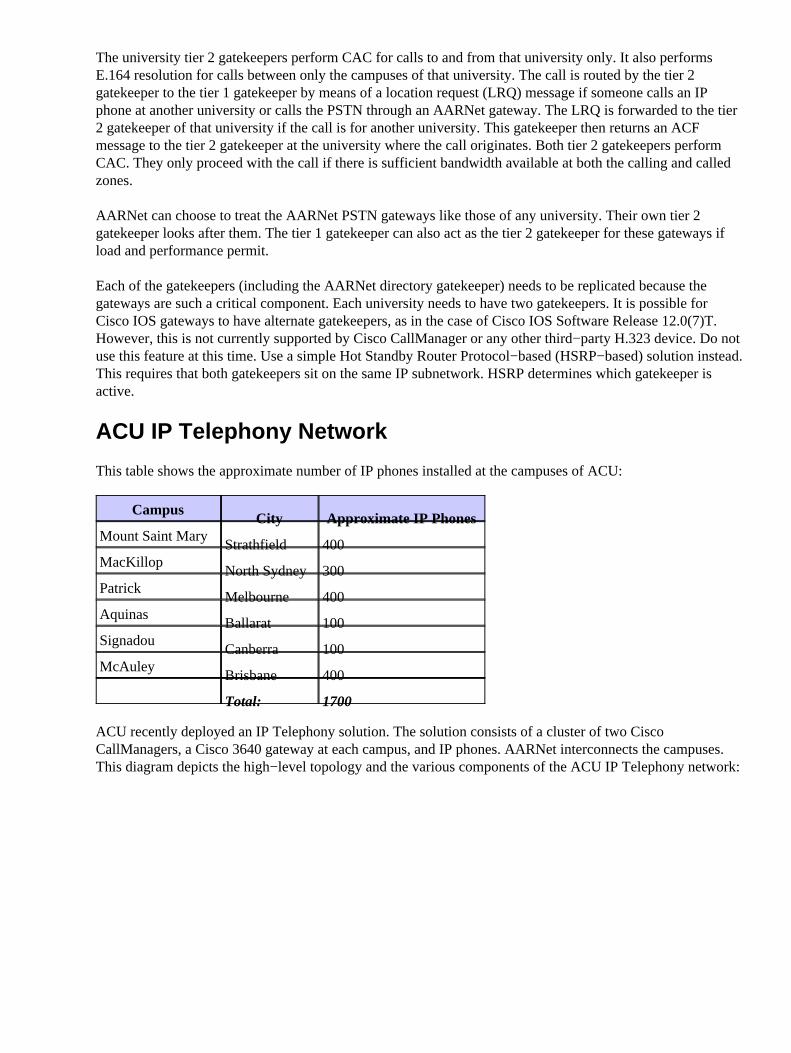
This table shows the approximate number of IP phones installed at the campuses of ACU:
CampusCity Approximate IP Phones
Mount Saint MaryStrathfield 400
MacKillopNorth Sydney 300
PatrickMelbourne 400
AquinasBallarat 100
SignadouCanberra 100
McAuleyBrisbane 400
Total: 1700
ACU recently deployed an IP Telephony solution. The solution consists of a cluster of two CiscoCallManagers, a Cisco 3640 gateway at each campus, and IP phones. AARNet interconnects the campuses.This diagram depicts the high−level topology and the various components of the ACU IP Telephony network:
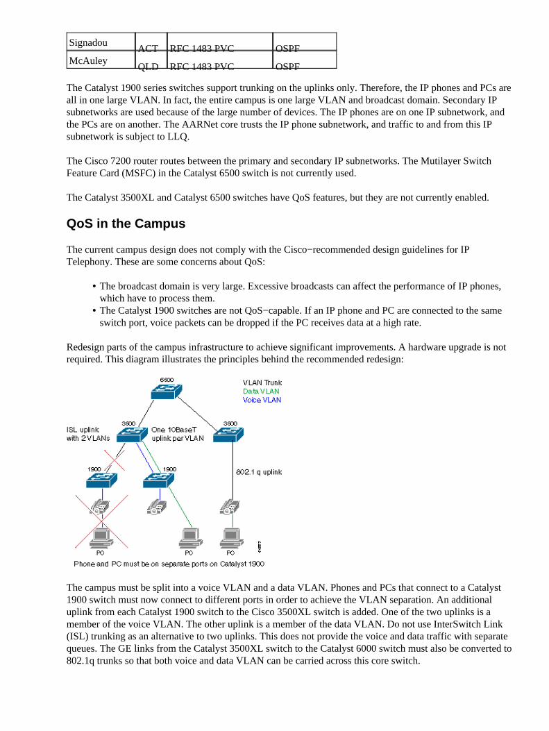
ACU Network Topology
This diagram shows a typical ACU campus. Each campus has three layers of Catalyst switches. The wiringcloset houses the older Catalyst 1900 switches. The Catalyst 1900 switches connect back to the Catalyst3500XL switch by means of Extended Framing. These connect back to a single Catalyst 6509 switch bymeans of Gigabit Ethernet (GE). A single Cisco 7200 VXR router connects the campus to AARNet by anATM VC to the local RNO.
The connectivity method to the RNO differs slightly from state to state, as this table shows. Victoria is basedon Classical IP over ATM (RFC 1577). The other RNOs have a straight PVC setup with RFC 1483encapsulation. Open Shortest Path First (OSPF) is the routing protocol used between ACU and the RNOs.
CampusState Connectivity to RNO
RoutingProtocol
Mount SaintMary
NSW RFC 1483 PVC OSPFMacKillop
NSW RFC 1483 PVC OSPFPatrick
VICRFC 1577 Classical IPover ATM
OSPF
AquinasVIC
RFC 1577 Classical IPover ATM
OSPF
SignadouACT RFC 1483 PVC OSPF
McAuleyQLD RFC 1483 PVC OSPF
The Catalyst 1900 series switches support trunking on the uplinks only. Therefore, the IP phones and PCs areall in one large VLAN. In fact, the entire campus is one large VLAN and broadcast domain. Secondary IPsubnetworks are used because of the large number of devices. The IP phones are on one IP subnetwork, andthe PCs are on another. The AARNet core trusts the IP phone subnetwork, and traffic to and from this IPsubnetwork is subject to LLQ.
The Cisco 7200 router routes between the primary and secondary IP subnetworks. The Mutilayer SwitchFeature Card (MSFC) in the Catalyst 6500 switch is not currently used.
The Catalyst 3500XL and Catalyst 6500 switches have QoS features, but they are not currently enabled.
QoS in the Campus
The current campus design does not comply with the Cisco−recommended design guidelines for IPTelephony. These are some concerns about QoS:
The broadcast domain is very large. Excessive broadcasts can affect the performance of IP phones,which have to process them.
•
The Catalyst 1900 switches are not QoS−capable. If an IP phone and PC are connected to the sameswitch port, voice packets can be dropped if the PC receives data at a high rate.
•
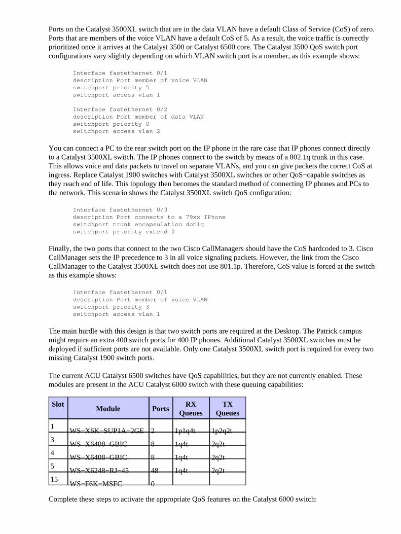
Redesign parts of the campus infrastructure to achieve significant improvements. A hardware upgrade is notrequired. This diagram illustrates the principles behind the recommended redesign:
The campus must be split into a voice VLAN and a data VLAN. Phones and PCs that connect to a Catalyst1900 switch must now connect to different ports in order to achieve the VLAN separation. An additionaluplink from each Catalyst 1900 switch to the Cisco 3500XL switch is added. One of the two uplinks is amember of the voice VLAN. The other uplink is a member of the data VLAN. Do not use InterSwitch Link(ISL) trunking as an alternative to two uplinks. This does not provide the voice and data traffic with separatequeues. The GE links from the Catalyst 3500XL switch to the Catalyst 6000 switch must also be converted to802.1q trunks so that both voice and data VLAN can be carried across this core switch.
Ports on the Catalyst 3500XL switch that are in the data VLAN have a default Class of Service (CoS) of zero.Ports that are members of the voice VLAN have a default CoS of 5. As a result, the voice traffic is correctlyprioritized once it arrives at the Catalyst 3500 or Catalyst 6500 core. The Catalyst 3500 QoS switch portconfigurations vary slightly depending on which VLAN switch port is a member, as this example shows:
Interface fastethernet 0/1description Port member of voice VLANswitchport priority 5switchport access vlan 1
Interface fastethernet 0/2description Port member of data VLANswitchport priority 0switchport access vlan 2
You can connect a PC to the rear switch port on the IP phone in the rare case that IP phones connect directlyto a Catalyst 3500XL switch. The IP phones connect to the switch by means of a 802.1q trunk in this case.This allows voice and data packets to travel on separate VLANs, and you can give packets the correct CoS atingress. Replace Catalyst 1900 switches with Catalyst 3500XL switches or other QoS−capable switches asthey reach end of life. This topology then becomes the standard method of connecting IP phones and PCs tothe network. This scenario shows the Catalyst 3500XL switch QoS configuration:
Interface fastethernet 0/3description Port connects to a 79xx IPhoneswitchport trunk encapsulation dot1qswitchport priority extend 0
Finally, the two ports that connect to the two Cisco CallManagers should have the CoS hardcoded to 3. CiscoCallManager sets the IP precedence to 3 in all voice signaling packets. However, the link from the CiscoCallManager to the Catalyst 3500XL switch does not use 801.1p. Therefore, CoS value is forced at the switchas this example shows:
Interface fastethernet 0/1description Port member of voice VLANswitchport priority 3switchport access vlan 1
The main hurdle with this design is that two switch ports are required at the Desktop. The Patrick campusmight require an extra 400 switch ports for 400 IP phones. Additional Catalyst 3500XL switches must bedeployed if sufficient ports are not available. Only one Catalyst 3500XL switch port is required for every twomissing Catalyst 1900 switch ports.
The current ACU Catalyst 6500 switches have QoS capabilities, but they are not currently enabled. Thesemodules are present in the ACU Catalyst 6000 switch with these queuing capabilities:
SlotModule Ports
RXQueues
TXQueues
1WS−X6K−SUP1A−2GE 2 1p1q4t 1p2q2t
3WS−X6408−GBIC 8 1q4t 2q2t
4WS−X6408−GBIC 8 1q4t 2q2t
5WS−X6248−RJ−45 48 1q4t 2q2t
15WS−F6K−MSFC 0 � �
Complete these steps to activate the appropriate QoS features on the Catalyst 6000 switch:
Tell the switch to provide QoS on a per−VLAN basis with this command:
Cat6K>(enable)set port qos 1/1−2,3/1−8,4/1−8 vlan−based
1.
Tell the switch to trust the CoS values received from the Catalyst 3500XL switch with this command:
Cat6K>(enable)set port qos 1/1−2,3/1−8,4/1−8 trust trust−cos
2.
The CoS must now be set to differentiated services code point (DSCP) mapping. This is required because theCatalyst 6000 switch rewrites the DSCP value in the IP header based on the received CoS value. VoIPsignaling packets must have a CoS of 3, rewritten with a DSCP of AF31 (26). RTP packets must have a CoSof 5, rewritten with a DSCP of EF (46). Issue this command:
Configure the MSFC to route between the various IP subnetworks.
QoS in the RNO
The current RNO design does not comply with Cisco−recommended design guidelines for IP Telephony.These concerns exist in regards to QoS:
LLQ is not applied on the Cisco ACU 7200 series WAN router.• The Patrick and Aquinas campuses connect to the RNO by means of ATM switched VCs (SVCs).LLQ is not supported on SVCs.
•
A Fast Ethernet−attached Cisco 7200 router connects the campus to an RNO by means of a 34 Mbps E4 ATMlink. Traffic can potentially queue up outbound on the 34M links because of the 4M versus 100M speedmismatch. Therefore, it is necessary to prioritize the voice traffic. Use LLQ. The Cisco 7200 routerconfiguration is similar to this example:
deny ip any any fragmentspermit udp any range any range 16384 32768 precedence critical
The bandwidth allocated to LLQ must be N x 24Kbps, where N is the number of simultaneous G.729 calls.
Set up one PVC from each of the Patrick and Aquinas Cisco 7200 routers to the AARNet router. ATM SVCsin the Victoria RNO do not support LLQ, as it is based on Classical IP over ATM (RFC 1577). The otheruniversities in the Victoria RNO can continue to use RFC 1577 for now. However, eventually replace theClassical IP over ATM infrastructure.
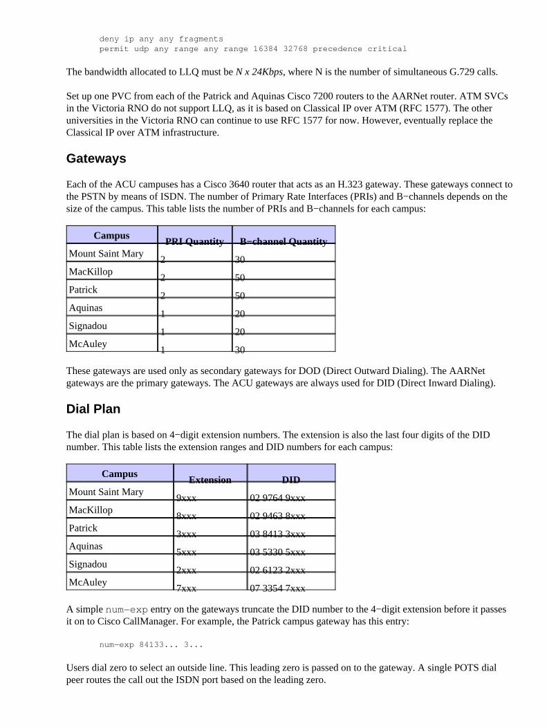
Gateways
Each of the ACU campuses has a Cisco 3640 router that acts as an H.323 gateway. These gateways connect tothe PSTN by means of ISDN. The number of Primary Rate Interfaces (PRIs) and B−channels depends on thesize of the campus. This table lists the number of PRIs and B−channels for each campus:
CampusPRI Quantity B−channel Quantity
Mount Saint Mary2 30
MacKillop2 50
Patrick2 50
Aquinas1 20
Signadou1 20
McAuley1 30
These gateways are used only as secondary gateways for DOD (Direct Outward Dialing). The AARNetgateways are the primary gateways. The ACU gateways are always used for DID (Direct Inward Dialing).
Dial Plan
The dial plan is based on 4−digit extension numbers. The extension is also the last four digits of the DIDnumber. This table lists the extension ranges and DID numbers for each campus:
CampusExtension DID
Mount Saint Mary9xxx 02 9764 9xxx
MacKillop8xxx 02 9463 8xxx
Patrick3xxx 03 8413 3xxx
Aquinas5xxx 03 5330 5xxx
Signadou2xxx 02 6123 2xxx
McAuley7xxx 07 3354 7xxx
A simple num−exp entry on the gateways truncate the DID number to the 4−digit extension before it passesit on to Cisco CallManager. For example, the Patrick campus gateway has this entry:
num−exp 84133... 3...
Users dial zero to select an outside line. This leading zero is passed on to the gateway. A single POTS dialpeer routes the call out the ISDN port based on the leading zero.
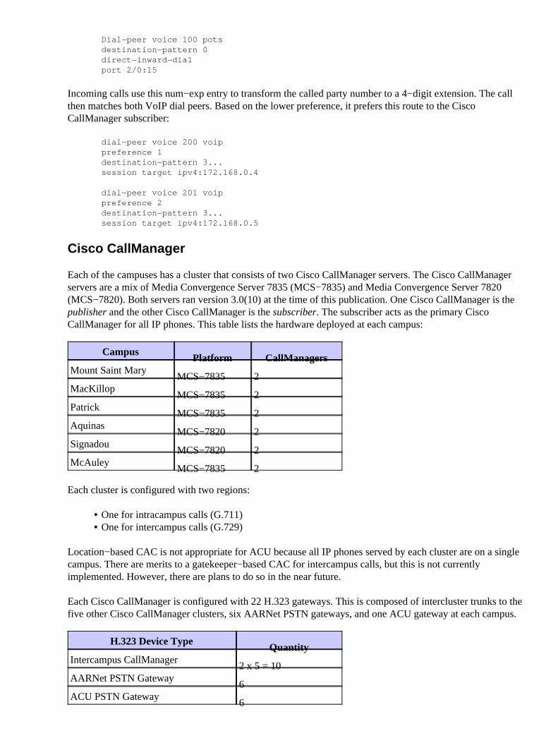
Incoming calls use this num−exp entry to transform the called party number to a 4−digit extension. The callthen matches both VoIP dial peers. Based on the lower preference, it prefers this route to the CiscoCallManager subscriber:
Each of the campuses has a cluster that consists of two Cisco CallManager servers. The Cisco CallManagerservers are a mix of Media Convergence Server 7835 (MCS−7835) and Media Convergence Server 7820(MCS−7820). Both servers ran version 3.0(10) at the time of this publication. One Cisco CallManager is thepublisher and the other Cisco CallManager is the subscriber. The subscriber acts as the primary CiscoCallManager for all IP phones. This table lists the hardware deployed at each campus:
CampusPlatform CallManagers
Mount Saint MaryMCS−7835 2
MacKillopMCS−7835 2
PatrickMCS−7835 2
AquinasMCS−7820 2
SignadouMCS−7820 2
McAuleyMCS−7835 2
Each cluster is configured with two regions:
One for intracampus calls (G.711)• One for intercampus calls (G.729)•
Location−based CAC is not appropriate for ACU because all IP phones served by each cluster are on a singlecampus. There are merits to a gatekeeper−based CAC for intercampus calls, but this is not currentlyimplemented. However, there are plans to do so in the near future.
Each Cisco CallManager is configured with 22 H.323 gateways. This is composed of intercluster trunks to thefive other Cisco CallManager clusters, six AARNet PSTN gateways, and one ACU gateway at each campus.
H.323 Device TypeQuantity
Intercampus CallManager2 x 5 = 10
AARNet PSTN Gateway6
ACU PSTN Gateway6
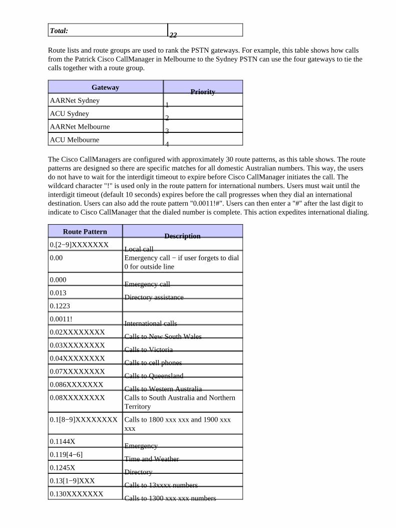
Total:22
Route lists and route groups are used to rank the PSTN gateways. For example, this table shows how callsfrom the Patrick Cisco CallManager in Melbourne to the Sydney PSTN can use the four gateways to tie thecalls together with a route group.
GatewayPriority
AARNet Sydney1
ACU Sydney2
AARNet Melbourne3
ACU Melbourne4
The Cisco CallManagers are configured with approximately 30 route patterns, as this table shows. The routepatterns are designed so there are specific matches for all domestic Australian numbers. This way, the usersdo not have to wait for the interdigit timeout to expire before Cisco CallManager initiates the call. Thewildcard character "!" is used only in the route pattern for international numbers. Users must wait until theinterdigit timeout (default 10 seconds) expires before the call progresses when they dial an internationaldestination. Users can also add the route pattern "0.0011!#". Users can then enter a "#" after the last digit toindicate to Cisco CallManager that the dialed number is complete. This action expedites international dialing.
Route PatternDescription
0.[2−9]XXXXXXXLocal call
0.00 Emergency call − if user forgets to dial0 for outside line
0.000Emergency call
0.013Directory assistance
0.1223�
0.0011!International calls
0.02XXXXXXXXCalls to New South Wales
0.03XXXXXXXXCalls to Victoria
0.04XXXXXXXXCalls to cell phones
0.07XXXXXXXXCalls to Queensland
0.086XXXXXXXCalls to Western Australia
0.08XXXXXXXX Calls to South Australia and NorthernTerritory
0.1[8−9]XXXXXXXX Calls to 1800 xxx xxx and 1900 xxxxxx
0.1144XEmergency
0.119[4−6]Time and Weather
0.1245XDirectory
0.13[1−9]XXXCalls to 13xxxx numbers
0.130XXXXXXXCalls to 1300 xxx xxx numbers
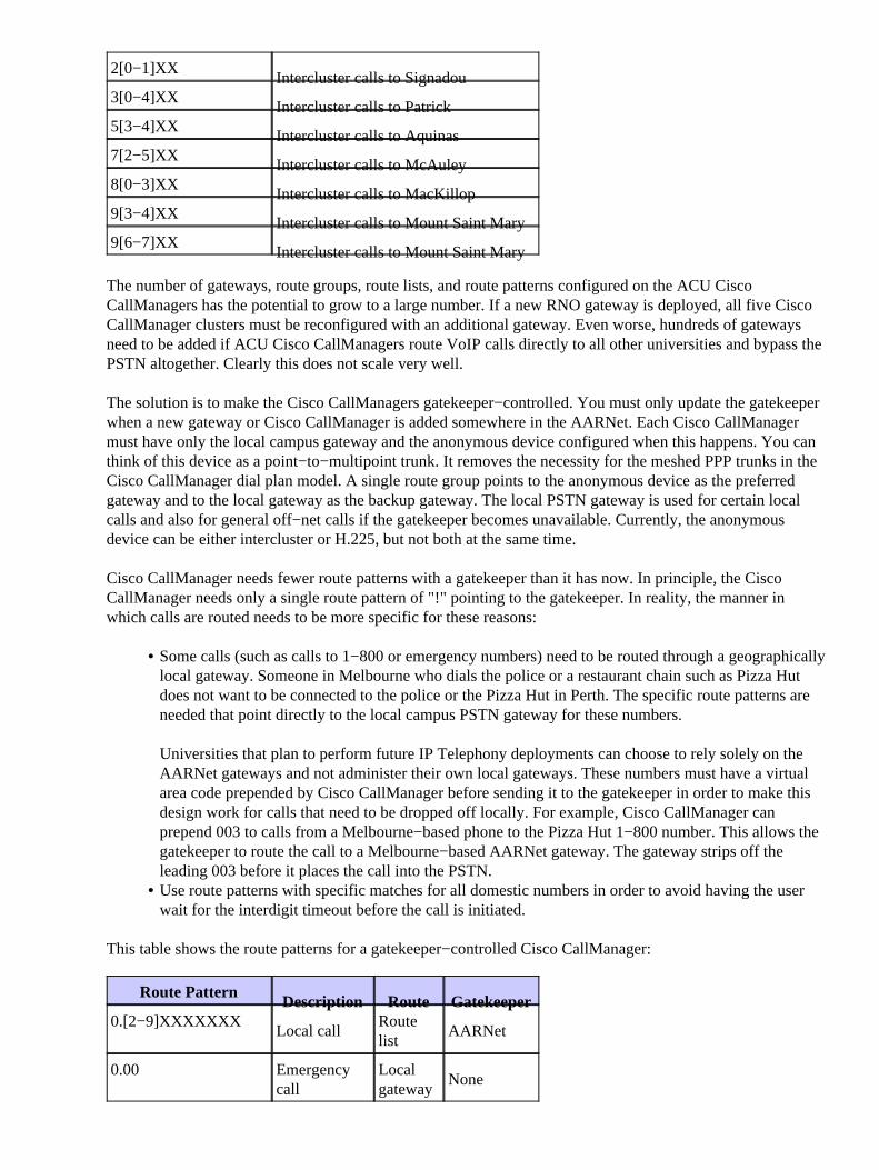
2[0−1]XXIntercluster calls to Signadou
3[0−4]XXIntercluster calls to Patrick
5[3−4]XXIntercluster calls to Aquinas
7[2−5]XXIntercluster calls to McAuley
8[0−3]XXIntercluster calls to MacKillop
9[3−4]XXIntercluster calls to Mount Saint Mary
9[6−7]XXIntercluster calls to Mount Saint Mary
The number of gateways, route groups, route lists, and route patterns configured on the ACU CiscoCallManagers has the potential to grow to a large number. If a new RNO gateway is deployed, all five CiscoCallManager clusters must be reconfigured with an additional gateway. Even worse, hundreds of gatewaysneed to be added if ACU Cisco CallManagers route VoIP calls directly to all other universities and bypass thePSTN altogether. Clearly this does not scale very well.
The solution is to make the Cisco CallManagers gatekeeper−controlled. You must only update the gatekeeperwhen a new gateway or Cisco CallManager is added somewhere in the AARNet. Each Cisco CallManagermust have only the local campus gateway and the anonymous device configured when this happens. You canthink of this device as a point−to−multipoint trunk. It removes the necessity for the meshed PPP trunks in theCisco CallManager dial plan model. A single route group points to the anonymous device as the preferredgateway and to the local gateway as the backup gateway. The local PSTN gateway is used for certain localcalls and also for general off−net calls if the gatekeeper becomes unavailable. Currently, the anonymousdevice can be either intercluster or H.225, but not both at the same time.
Cisco CallManager needs fewer route patterns with a gatekeeper than it has now. In principle, the CiscoCallManager needs only a single route pattern of "!" pointing to the gatekeeper. In reality, the manner inwhich calls are routed needs to be more specific for these reasons:
Some calls (such as calls to 1−800 or emergency numbers) need to be routed through a geographicallylocal gateway. Someone in Melbourne who dials the police or a restaurant chain such as Pizza Hutdoes not want to be connected to the police or the Pizza Hut in Perth. The specific route patterns areneeded that point directly to the local campus PSTN gateway for these numbers.
Universities that plan to perform future IP Telephony deployments can choose to rely solely on theAARNet gateways and not administer their own local gateways. These numbers must have a virtualarea code prepended by Cisco CallManager before sending it to the gatekeeper in order to make thisdesign work for calls that need to be dropped off locally. For example, Cisco CallManager canprepend 003 to calls from a Melbourne−based phone to the Pizza Hut 1−800 number. This allows thegatekeeper to route the call to a Melbourne−based AARNet gateway. The gateway strips off theleading 003 before it places the call into the PSTN.
•
Use route patterns with specific matches for all domestic numbers in order to avoid having the userwait for the interdigit timeout before the call is initiated.
•
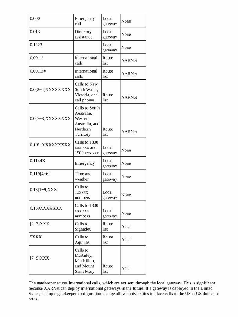
This table shows the route patterns for a gatekeeper−controlled Cisco CallManager:
Route PatternDescription Route Gatekeeper
0.[2−9]XXXXXXXLocal call
Routelist
AARNet
0.00 Emergencycall
Localgateway
None
0.000 Emergencycall
Localgateway
None
0.013 Directoryassistance
Localgateway
None
0.1223�
Localgateway
None
0.0011! Internationalcalls
Routelist
AARNet
0.0011!# Internationalcalls
Routelist
AARNet
0.0[2−4]XXXXXXXXCalls to NewSouth Wales,Victoria, andcell phones
Routelist
AARNet
0.0[7−8]XXXXXXXX
Calls to SouthAustralia,WesternAustralia, andNorthernTerritory
Routelist
AARNet
0.1[8−9]XXXXXXXXCalls to 1800xxx xxx and1900 xxx xxx
Localgateway
None
0.1144XEmergency
Localgateway
None
0.119[4−6] Time andweather
Localgateway
None
0.13[1−9]XXXCalls to13xxxxnumbers
Localgateway
None
0.130XXXXXXXCalls to 1300xxx xxxnumbers
Localgateway
None
[2−3]XXX Calls toSignadou
Routelist
ACU
5XXX Calls toAquinas
Routelist
ACU
[7−9]XXX
Calls toMcAuley,MacKillop,and MountSaint Mary
Routelist
ACU
The gatekeeper routes international calls, which are not sent through the local gateway. This is significantbecause AARNet can deploy international gateways in the future. If a gateway is deployed in the UnitedStates, a simple gatekeeper configuration change allows universities to place calls to the US at US domesticrates.
The gatekeeper performs intercluster call routing based on the 4−digit ACU extension. This address spacemost likely overlaps with other universities. This dictates that ACU administer its own gatekeeper and use theAARNet gatekeeper as a directory gatekeeper. The gatekeeper column in this table indicates whether the callrouting is performed by the ACU gatekeeper or the AARNet gatekeeper.
Note: The sole caveat with the proposed gatekeeper solution is that the anonymous device can currently beeither intercluster or H.225, but not both at the same time. Cisco CallManager relies on the gatekeeper to routecalls to both gateways (H.225) and other Cisco CallManagers (intercluster) with the proposed design. Theworkaround for this issue is to either not use the gatekeeper for intercluster routing or to treat all calls via thegatekeeper as H.225. The latter workaround means that some supplementary features might be unavailable onintercluster calls.
Voice Mail
ACU had three Active Voice Repartee OS/2−based voice mail servers with Dialogic phone boards prior to themigration to IP Telephony. The plan is to reuse these servers in the IP Telephony environment. Whenimplemented, each Repartee server connects to a Cisco CallManager by means of a simplified message deskinterface (SMDI) and a Catalyst 6000 24−Port Foreign Exchange Station (FXS) card. This provides voicemail for three of the six campuses, which leaves three campuses without voice mail. It is not possible toproperly share one Repartee server between users on two Cisco CallManager clusters because there is no wayto propagate the message waiting indicator (MWI) across the intercluster H.323 trunk.
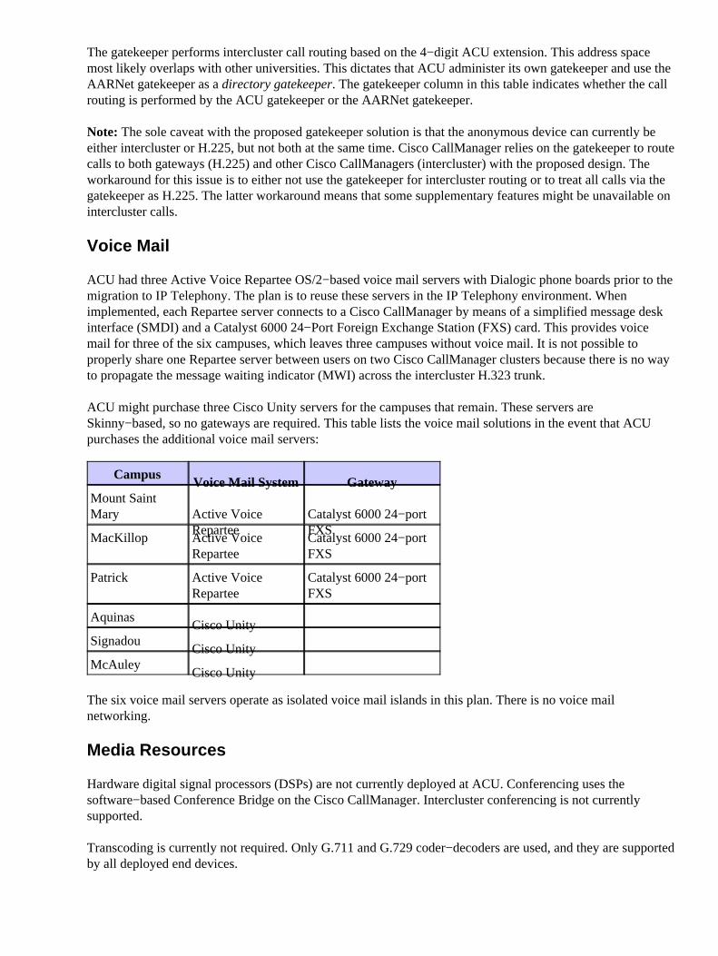
ACU might purchase three Cisco Unity servers for the campuses that remain. These servers areSkinny−based, so no gateways are required. This table lists the voice mail solutions in the event that ACUpurchases the additional voice mail servers:
CampusVoice Mail System Gateway
Mount SaintMary Active Voice
ReparteeCatalyst 6000 24−portFXS
MacKillop Active VoiceRepartee
Catalyst 6000 24−portFXS
Patrick Active VoiceRepartee
Catalyst 6000 24−portFXS
AquinasCisco Unity �
SignadouCisco Unity �
McAuleyCisco Unity �
The six voice mail servers operate as isolated voice mail islands in this plan. There is no voice mailnetworking.
Media Resources
Hardware digital signal processors (DSPs) are not currently deployed at ACU. Conferencing uses thesoftware−based Conference Bridge on the Cisco CallManager. Intercluster conferencing is not currentlysupported.
Transcoding is currently not required. Only G.711 and G.729 coder−decoders are used, and they are supportedby all deployed end devices.
Fax and Modem Support
Fax and modem traffic is not currently supported by the ACU IP Telephony network. The university plans toutilize the Catalyst 6000 24−Port FXS card for this purpose.
Software Versions
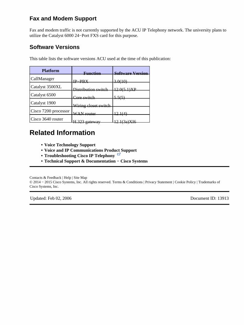
This table lists the software versions ACU used at the time of this publication:
PlatformFunction Software Version
CallManagerIP−PBX 3.0(10)
Catalyst 3500XLDistribution switch 12.0(5.1)XP
Catalyst 6500Core switch 5.5(5)
Catalyst 1900Wiring closet switch �
Cisco 7200 processorWAN router 12.1(4)
Cisco 3640 routerH.323 gateway 12.1(3a)XI6
Related Information
Voice Technology Support• Voice and IP Communications Product Support• Troubleshooting Cisco IP Telephony • Technical Support & Documentation − Cisco Systems•