Case Study: Movable Bed Model Scaling for Bed LoadSediment Exclusion at Intake Structure on Rio Grande
Jungseok Ho1; Julie Coonrod2; Tom Gill3; and Brent Mefford4
Abstract: Results of a laboratory modeling study are presented for excluding bed load sediment from a diversion/intake structure on theRio Grande in Albuquerque, New Mexico. To achieve model similitude, crushed coal was used to model the prototype sediment in a 1:24scaled model with an exaggerated slope such that shear force is adequately modeled. The Shields parameters and critical Shieldsparameters were matched between the prototype and the model, resulting in similar grain Reynolds numbers. Twenty-four tests, whereguiding walls, submerged vanes, and/or the angle of the intake bay were altered, were conducted for a single river and diversion flow rateto develop the best performing sediment exclusion system at the intake structure. Independent vanes with 45° rotated intake bays wererecommended for the most effective sediment exclusion at the intake structure.
DOI: 10.1061/�ASCE�HY.1943-7900.0000149
CE Database subject headings: Diversion structures; Intake structures; Sediment; Submerging; Bed loads; Rio Grande; NewMexico.
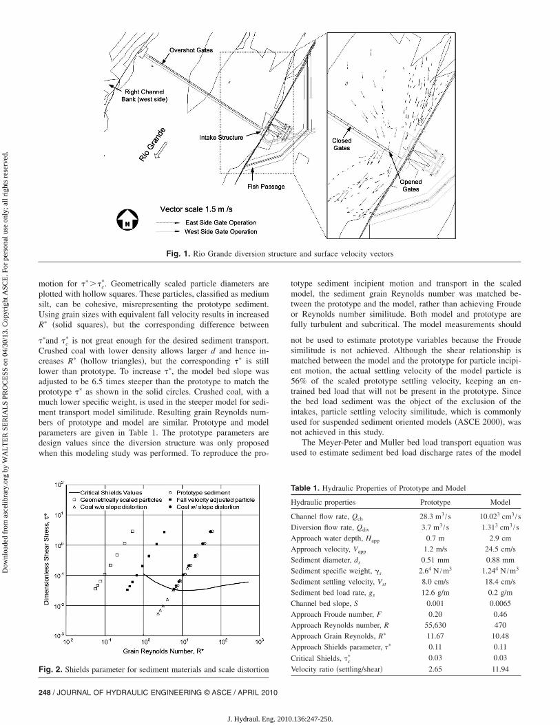
A 1:24 scale distorted movable bed model of the Rio Grandediversion structure was constructed and tested at the U.S. Bureauof Reclamation, Water Resources Research Laboratory in Denver,Colorado. The diversion structure is composed of overshot gatesthat extend across the channel, a river intake structure, and a fishpassage �Fig. 1�. The physical model allowed for a variation ingate operations and intake structure design. Fig. 1 shows the es-timated prototype two-dimensional surface velocity vectors infront of the intake structure for a river flow rate of 28.3 m3 /s with3.7 m3 /s diverted. The initially designed intake structure, posi-tioned perpendicular to the river, consisted of two 7.3-m-wideintake bays to divert a maximum of 5.2 m3 /s. An intake guidingwing wall and 0.5-m-high bottom weir were initially designed toprevent sediment transport into the intake bays. The actual struc-ture is expected to be in full operation in 2009. The purpose ofthis modeling study was to reproduce prototype sediment trans-
1Research Associate, Dept. of Civil Engineering, Univ. of NewMexico, Albuquerque, NM 87131 �corresponding author�. E-mail:[email protected]
2Associate Professor, Dept. of Civil Engineering, Univ. of NewMexico, Albuquerque, NM 87131. E-mail: [email protected]
3Hydraulic Engineer, Water Resources Research Laboratory, U.S. Bu-reau of Reclamation, Denver, CO 80225. E-mail: [email protected]
4Technical Specialist, Water Resources Research Laboratory, U.S. Bu-reau of Reclamation, Denver, CO 80225. E-mail: [email protected]
port of the diversion structure on the Rio Grande to determine thebest sediment exclusion intake structure design.
Movable Bed Model Similitude
The Shields diagram is often used for analyzing the ratio of chan-nel bed shear force to sediment buoyant weight for a range ofgrain Reynolds numbers, R�=u�ds /�, where u� is the shear veloc-ity, ds is the sediment diameter, and � is the fluid kinematic vis-cosity. The curve indicates when significant movement of bedparticles is likely to begin, though it is not an exact thresholdcondition for incipient motion �ASCE 2000�. Pugh and Dodge�1991� suggested that the difference of the Shields parameter ���,dimensionless shear� to the critical Shields parameter ��c
�� shouldbe the same in the model and prototype to achieve similarity ofsediment transport between the model and the prototype
��� − �c��m
��� − �c��p
= 1; �� =�0
��s − ��ds�1�
where subscripts m and p represent model and prototype, respec-tively; �0=�u�
2=bed shear stress, with � being the fluid density; �s
and �=specific weights of sediment and water, respectively. Theirscaling technique was applied to a 1:10 scaled sediment erosionmodel and verified with prototype measurement. Mefford �2004�followed the suggestion of Pugh and Dodge �1991� in a 1:20 scalemovable bed model for a river surface water intake structure hy-draulic performance test. The prototype bed shear was reproducedusing a distorted material for prototype sediment. Similarly, forthis study, the prototype �� was compared with a different scaledmodel �� as shown in Fig. 2. The R� of the prototype particle�ds=0.51 mm� and �� for eight hydraulic radii ranging from 0.03
to 2.4 m are plotted with the hollow circular dots. Particles are in
motion for ����c�. Geometrically scaled particle diameters are
plotted with hollow squares. These particles, classified as mediumsilt, can be cohesive, misrepresenting the prototype sediment.Using grain sizes with equivalent fall velocity results in increasedR� �solid squares�, but the corresponding difference between
��and �c� is not great enough for the desired sediment transport.
Crushed coal with lower density allows larger d and hence in-creases R� �hollow triangles�, but the corresponding �� is stilllower than prototype. To increase ��, the model bed slope wasadjusted to be 6.5 times steeper than the prototype to match theprototype �� as shown in the solid circles. Crushed coal, with amuch lower specific weight, is used in the steeper model for sedi-ment transport model similitude. Resulting grain Reynolds num-bers of prototype and model are similar. Prototype and modelparameters are given in Table 1. The prototype parameters aredesign values since the diversion structure was only proposedwhen this modeling study was performed. To reproduce the pro-
Fig. 1. Rio Grande diversion s
Fig. 2. Shields parameter for sediment materials and scale distortion
totype sediment incipient motion and transport in the scaledmodel, the sediment grain Reynolds number was matched be-tween the prototype and the model, rather than achieving Froudeor Reynolds number similitude. Both model and prototype arefully turbulent and subcritical. The model measurements should
not be used to estimate prototype variables because the Froudesimilitude is not achieved. Although the shear relationship ismatched between the model and the prototype for particle incipi-ent motion, the actual settling velocity of the model particle is56% of the scaled prototype settling velocity, keeping an en-trained bed load that will not be present in the prototype. Sincethe bed load sediment was the object of the exclusion of theintakes, particle settling velocity similitude, which is commonlyused for suspended sediment oriented models �ASCE 2000�, wasnot achieved in this study.
The Meyer-Peter and Muller bed load transport equation wasused to estimate sediment bed load discharge rates of the model
Table 1. Hydraulic Properties of Prototype and Model
Hydraulic properties Prototype Model
Channel flow rate, Qch 28.3 m3 /s 10.023 cm3 /s
Diversion flow rate, Qdiv 3.7 m3 /s 1.313 cm3 /s
Approach water depth, Happ 0.7 m 2.9 cm
Approach velocity, Vapp 1.2 m/s 24.5 cm/s
Sediment diameter, ds 0.51 mm 0.88 mm
Sediment specific weight, �s 2.64 N /m3 1.244 N /m3
and the prototype. Shen �1971� recommended a bed load scalingfor sand and gravel dominated systems using the Meyer-Peter andMuller equation because sediment particle densities of model andprototype as well as model slope distortions can be considered.The equation may be expressed as �Vanoni 1975�
� kr
kr��3/2
�RhS = 0.047��s − ��dm + 0.25��
g�1/3� ��s − ��
�s�2/3
gS2/3
�2�
where kr represents a roughness coefficient; kr�=26 /d901/6; Rh and
S=hydraulic radius and bed slope, respectively; dm=mean sedi-ment diameter; g=acceleration due to gravity; and gS represents aunit bed load rate in metric tons per meter per second. This equa-tion was manipulated to estimate gS for both model and prototype,and then multiplied by respective channel widths, as a basis forscaling the transport rate given differing prototype/model sedi-ment densities as well as model slope distortions �Gill 2004�. Thelinear relationship, �gS�p=63.2� �gS�m, between the bed load rateof the prototype and the model was derived. Crushed coal wascontinuously and uniformly distributed at the entry of the experi-mental box �12.7 m upstream of the intake� using electric operat-ing feeders according to the derived bed load rate relationship.The crushed coal resulted in a 4-cm layer simulating bed load inthe river. One hour after initiating an experiment, diverted coal atthe intake bays was collected for 30 min and wet weighed todetermine the sediment transported. The experiment was repeatedfor a total of three measurements that were averaged for eachintake design. Although the modeling approach cannot yet beverified by prototype comparison, it was verified with a numericalmodel of the prototype �Ho 2006�.
Sediment Exclusion at Intake Structure
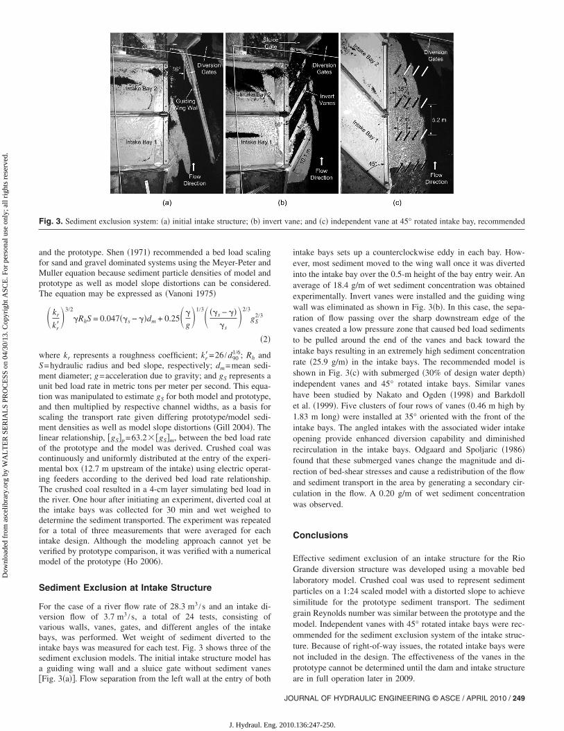
For the case of a river flow rate of 28.3 m3 /s and an intake di-version flow of 3.7 m3 /s, a total of 24 tests, consisting ofvarious walls, vanes, gates, and different angles of the intakebays, was performed. Wet weight of sediment diverted to theintake bays was measured for each test. Fig. 3 shows three of thesediment exclusion models. The initial intake structure model hasa guiding wing wall and a sluice gate without sediment vanes
�Fig. 3�a��. Flow separation from the left wall at the entry of both
JO
J. Hydraul. Eng. 2010
intake bays sets up a counterclockwise eddy in each bay. How-ever, most sediment moved to the wing wall once it was divertedinto the intake bay over the 0.5-m height of the bay entry weir. Anaverage of 18.4 g/m of wet sediment concentration was obtainedexperimentally. Invert vanes were installed and the guiding wingwall was eliminated as shown in Fig. 3�b�. In this case, the sepa-ration of flow passing over the sharp downstream edge of thevanes created a low pressure zone that caused bed load sedimentsto be pulled around the end of the vanes and back toward theintake bays resulting in an extremely high sediment concentrationrate �25.9 g/m� in the intake bays. The recommended model isshown in Fig. 3�c� with submerged �30% of design water depth�independent vanes and 45° rotated intake bays. Similar vaneshave been studied by Nakato and Ogden �1998� and Barkdollet al. �1999�. Five clusters of four rows of vanes �0.46 m high by1.83 m long� were installed at 35° oriented with the front of theintake bays. The angled intakes with the associated wider intakeopening provide enhanced diversion capability and diminishedrecirculation in the intake bays. Odgaard and Spoljaric �1986�found that these submerged vanes change the magnitude and di-rection of bed-shear stresses and cause a redistribution of the flowand sediment transport in the area by generating a secondary cir-culation in the flow. A 0.20 g/m of wet sediment concentrationwas observed.
Conclusions
Effective sediment exclusion of an intake structure for the RioGrande diversion structure was developed using a movable bedlaboratory model. Crushed coal was used to represent sedimentparticles on a 1:24 scaled model with a distorted slope to achievesimilitude for the prototype sediment transport. The sedimentgrain Reynolds number was similar between the prototype and themodel. Independent vanes with 45° rotated intake bays were rec-ommended for the sediment exclusion system of the intake struc-ture. Because of right-of-way issues, the rotated intake bays werenot included in the design. The effectiveness of the vanes in theprototype cannot be determined until the dam and intake structure
e; and �c� independent vane at 45° rotated intake bay, recommended
Barkdoll, B., Ettema, R., and Odgaard, A.J. �1999�. “Sediment control atlateral diversions: limits and enhancements to vane use.” J. Hydraul.Eng., 125�8�, 855–861.
Gill, T. �2004�. “Physical model study: City of Albuquerque drinkingwater project, sediment management at the proposed Rio Grande di-version.” Hydraulic Laboratory Rep. No. HL-2004-01, Water Re-sources Research Laboratory, U.S. Bureau of Reclamation, U.S. Dept.of the Interior, Denver.
Ho, J. �2006�. “Hydraulic modeling study to determine diversion struc-ture impacts.” Ph.D thesis, Univ. of New Mexico, Albuquerque, N.M.
Mefford, B. �2004�. “Elwha River surface-water intake structure.” Hy-