Source of Acquisition NASA Johnson Space Center CASE STUDY OF THE SPACE SHUTTLE COCKPIT AVIONICS UPGRADE SOFTWARE Roscoe C. Ferguson, Hirain C. Thonzpson, United Space Alliance, LLC Houstorz, Texas Abstract I. Introduction The purpose of the Space Shuttle Cockpit Avionics Upgrade project was to reduce crew workload and improve situational awareness. The upgrade was to augment the Shuttle avionics system with new hardware and software. An early version of this system was used to gather human factor statistics in the Space Shuttle Motion Simulator of the Johnson Space Center for one month by multiple teams of astronauts. The results were - ~ ~ A ~ e a i t - - was determined that the system provided a better than expected increase in situational awareness and reduction in crew workload. Even with all of the benefits nf the system, NASA cance!!ed the project towards the end of the development cycle. A major success of this project was the validation of the hardware architecture and software design. This was significant because the project incorporated new technology and approaches for the development of human rated space software. This paper serves as a case study to document knowledge gained and techniques that can be applied for future space avionics development efforts. The major technological advances were the use of reflective memory concepts for data acquisition and the incorporation of Commercial off the Shelf (COTS) products in a human rated space avionics system. The infused COTS products included a real time operating system, a resident linker and loader, a display generation tool set, and a network data manager. Some of the successful design concepts were the engineering of identical outputs in multiple avionics boxes using an event driven approach and inter-computer The user interface of the Space Shuttle was designed in the 1970's. The human factors of the system did not evolve to meet those present in today's modem cockpits of both commercial and military aircraft. Even though the Space Shuttle Program performed a successful effort to upgrade the analog "steam gauges" into flat screen displays, the approach for providing the core information remained unchanged. The Cockpit Avionics ~~ade(GAU)pr~~-1~a-~-t~d&essthi~ssue. NASA cancelled the project towards the end of the development phase. However, before this event, a successful early evaluation of the system (Figure 1) was performed using multiple teams of astronauts in the Space Shuttle Motion Simulator (SMS) of the Johnson Space Center. The NASA Ames Research Center compiled the results of the evaluation and determined that the new system provided a significant increase in situational awareness and reduction in crew workload [I]. -- communication, a reconfigurable data acquisition engine, the use of dyiiailic IiilEiig at imtimz, aid Figure I. CAU Pre-SMS valuation' the use of a dynamic bus bandwidth allocation algorithm. Other significant experiences captured were the use of prototyping to reduce risk, and the correct balance between Object Oriented and Functional based programming. ' Photo courtesy of Ronnie Montgomery https://ntrs.nasa.gov/search.jsp?R=20070018256 2018-05-20T02:55:57+00:00Z
Transcript
Source of Acquisition NASA Johnson Space Center
CASE STUDY OF THE SPACE SHUTTLE COCKPIT AVIONICS UPGRADE SOFTWARE
Roscoe C. Ferguson, Hirain C. Thonzpson, United Space Alliance, LLC Houstorz, Texas
Abstract I. Introduction The purpose of the Space Shuttle Cockpit
Avionics Upgrade project was to reduce crew workload and improve situational awareness. The upgrade was to augment the Shuttle avionics system with new hardware and software. An early version of this system was used to gather human factor statistics in the Space Shuttle Motion Simulator of the Johnson Space Center for one month by multiple teams of astronauts. The results were
- ~ ~ A ~ e a i t - - was determined that the system provided a better than expected increase in situational awareness and reduction in crew workload. Even with all of the benefits nf the system, NASA cance!!ed the project towards the end of the development cycle.
A major success of this project was the validation of the hardware architecture and software design. This was significant because the project incorporated new technology and approaches for the development of human rated space software. This paper serves as a case study to document knowledge gained and techniques that can be applied for future space avionics development efforts. The major technological advances were the use of reflective memory concepts for data acquisition and the incorporation of Commercial off the Shelf (COTS) products in a human rated space avionics system. The infused COTS products included a real time operating system, a resident linker and loader, a display generation tool set, and a network data manager. Some of the successful design concepts were the engineering of identical outputs in multiple avionics boxes using an event driven approach and inter-computer
The user interface of the Space Shuttle was designed in the 1970's. The human factors of the system did not evolve to meet those present in today's modem cockpits of both commercial and military aircraft. Even though the Space Shuttle Program performed a successful effort to upgrade the analog "steam gauges" into flat screen displays, the approach for providing the core information remained unchanged. The Cockpit Avionics ~~ade(GAU)pr~~-1~a-~-t~d&essthi~ssue. NASA cancelled the project towards the end of the development phase. However, before this event, a successful early evaluation of the system (Figure 1) was performed using multiple teams of astronauts in the Space Shuttle Motion Simulator (SMS) of the Johnson Space Center. The NASA Ames Research Center compiled the results of the evaluation and determined that the new system provided a significant increase in situational awareness and reduction in crew workload [I].
- - communication, a reconfigurable data acquisition engine, the use of dyiiailic IiilEiig at imtimz, aid Figure I. CAU Pre-SMS valuation' the use of a dynamic bus bandwidth allocation algorithm. Other significant experiences captured were the use of prototyping to reduce risk, and the correct balance between Object Oriented and Functional based programming. ' Photo courtesy of Ronnie Montgomery
The CAU project incorporated technology and design approaches that will most likely be used to implement the systems to support NASA's new exploration vision. For technology, this includes the use of COTS products, modern programming languages, and modern hardware piatforins. For design approaches, this includes the design of data acquisition systems, bus profile management, and multi-string systems. This paper provides a synopsis of the major software design concepts used in the CAU project. It also provides information on the project's experience with using COTS products and problems encountered using new technology in a space man-rated project. It concludes with suggestions and considerations for frlture 2vicnics projects.
2. CAU Design Driver Overview The user interface of the current Space S h u E -
system provides an enormous amount of data for processing by the crew. The problem is that the crew has to perform "data mining" to extract information on system status and probiem diagnosis. The core data is provided to the crew using three CRT style display units to share over 100 available display formats. Each display format generally provides data from a single avionics data source. The Space Shuttle has multiple subsystems that are controlled by software that can be executed in up to five General Purpose Computers (GPCs) at a single time. Furthermore, the software load can vary across the set. The crew relies on heavy training, memorization, ground support, and paper lookups to process critical information.
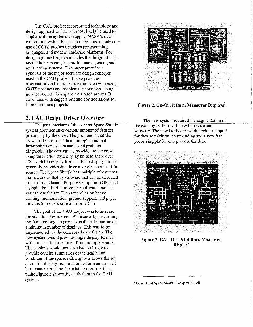
The goal of the CAU project was to increase the situational awareness of the crew by performing the "data mining" to provide useful information on a minimum number of displays. This was to be implemented via the concept of data fusion. The new system would provide single display formats with information integrated from multiple sources. The displays would include advanced logic to provide concise summaries of the health and condition of the spacecraft. Figure 2 shows the set of control displays required to perform an on-orbit burn maneuver using the existing user interface, while Figure 3 shows the equivalent in the CAU system.
Figure 2. On-Orbit Burn Maneuver ~ i s ~ l a ~ s *
The new system required the augmentation of the existing system with new hardware and software. The new hardware would include support for data acquisition, commanding and a new fast processing platfornl to process the data.
Figure 3. CAU On-Orbit Burn Maneuver ~ i s ~ l a ~ ~
Courtesy of Space Shuttle Cockpit Council
3. CAU Hardware Architecture Overview
The CAU hardware architecture was driven by the concept of data fusion. The GPC was to serve as the primzq datlta sclurce. The preject war,ted to obtain GPC data without perturbing the existing architecture. The Shuttle architecture uses 1 Mb/s Manchester encoded serial buses, which is referred to as a Multiplexer Interface Adapter (MIA) bus, to comnunicate between devices. The speed of the MIA Bus was not adequate to provide the required amount of data at a high rate. Also, the project wanted to minimize the effect on the existing GPC flight software. The ingenious insight was to use the GPC facility support interface to acquire the data. This interface provides access to the GPC local bus. A solution was devised where the memory transactions on the local bus would be snooped, senalized, and transferred to a device creating a reflective memory image of the GPC.
The project developed two hardware units to augment the existing avionics system. These were the Avionics Ground Equipment Serializer (AGES) and the Command and Data Processor (CDP). The AGES was the implementation of the device to snoop the GPC memory transactions for the formulation of reflective memory images. The CDP was to replace the existing user interface computers,
The CDP was composed of the SP103S Single Board Computer (SBC), the Deserializer Module (DSM) board, Keyboard Input Output (KIO) board, and the MIA Input Output (MIO) board. Each was manufactured by Lockheed Martin - Owego.
The SP 103 S was to provide the core platform for data processing. It was designed around the PowerPC 7455 processor and provided external interface support via UARTs and Ethernet.
The DSM reconstructed the transactions from the AGES into GPC reflective memory images (1 Mbyte). There was a hardware channel to support a reflective memory image for each of the five GPCs. Each channel was equipped with ability to freeze the r.o~tents of its reflective memory image using trigger points based on address and memory transaction type. This was used to provide the ability to obtain homogenous data. FIFO's were used to buffer incoming memory transactions while the image was frozen.
The KIO provided for FLASH mass storage, discrete interface support, keyboard interface support, 22d 1553 bus interface support. The MI0 provided interface support to the 1 Mbls bus system. In particular, support was provided for the GPC comaiid iiiterface aiid f ~ r the snooping of data on the Orbiter Instrumentation (GI) Bus. The 01 Bus was another source of information to be used for data fusion.
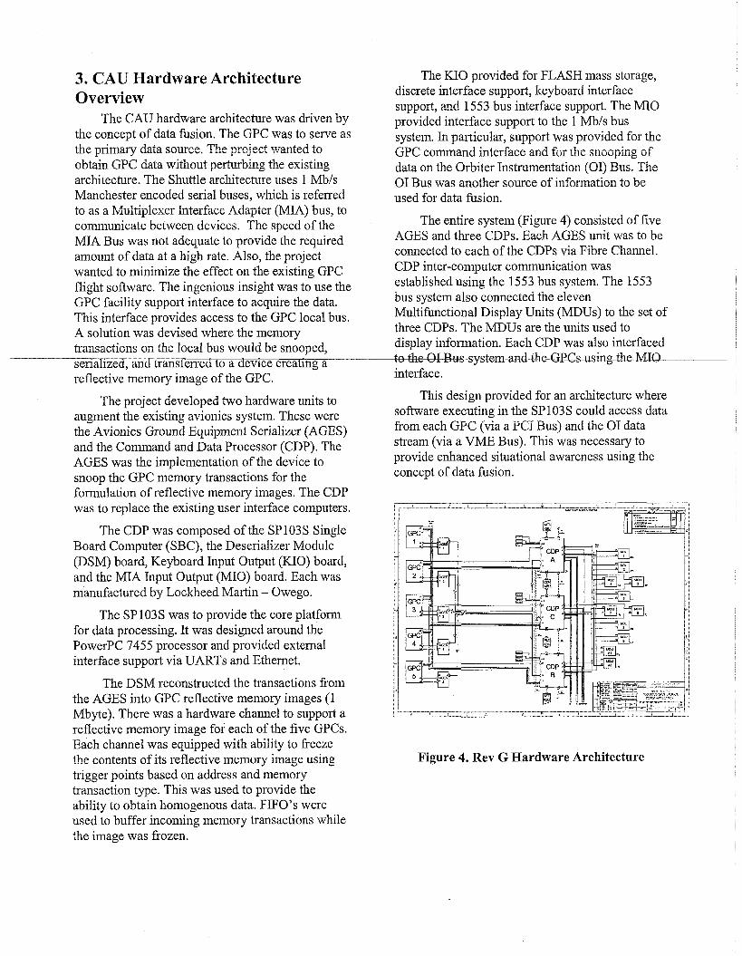
The entire system (Figure 4) consisted of five AGES and three CDPs. Each AGES unit was to be connected to each of the CDPs via Fibre Channel. CDP inter-computer communication was established using the 1553 bus system. The 1553 bus system also connected the eleven Multifunctional Display Units (MDUs) to the set of three CDPs. The MDUS are the units used to display information. Each CDP was also interfaced , n - n T w r . r r o f p m a n t l f h p r ; P @ k M T n
interface.
This design provided for an architecture where software executing in the SP 103 S could access data from each GPC (via a PC1 Bus) and the 0 1 data stream (via a VME Bus). This was necessary to provide enhanced situational awareness using the concept of data fusion.
Figure 4. Rev G Hardware Architecture
4. CAU Software Architecture Overview
The software for the CAU system was organized into three modes. These were Normal, D&a Services, a3d Maintenmce Modes. Each mode was a distinct set of software designed for a system operational task based on criticality. Non-critical software modes could be isolated to prevent operational malknctions by the non-initialization of hardware resources and the absence of its support software modules. Normal Mode was to be used during normal systems operation for all flight phases. This mode had access to all data and bus resources. It drove MDU displays and provided commanding back to the GPCs. Data Services Mode was to be used during orbit operations. It had access to incoming data, but not the 1553 or Shuttle 1 Mb/s bus systems. It was to serve as a data sewer
- where system data would be sent over an btnernet bus to a laptop computer with custom data processing. Maintenance Mode was to be used to perform software maintenance operations such as load updates. It had no access to incoming data and buses. This paper focuses on the design of the software for Normal Mode. However, a significant amount of Normal Mode software components were reused to support the other modes.
Figure 4. Normal Mode Software Architecture
The Normal Mode (Figure 4) software was composed of System Software (SSW), a COTS RTOS, and applications. The system software was
organized into packages which each provided a related area of management and services. The packages were System Management, System Control, Data Management, System Utilities, and System Interface.
4.1 SS W Systein Management Package The System Management package provided support for initizlizztion, IrZ m~mgement, display management, device management, health management, and inter-computer communication management (ICC). The CDP Initialization provided the ability to initialize the CDP using tables specifying software files to load and initialization functions to invoke. It used the dynamic loader and linker of the RTOS to provide "DLL style" capability for the system. It also performed operations wch as the invocation of ' 3 ~ c ~ ~ r n c e ~ ~ c ~ e system errors caused by system interruption. The I 0 Management system provided the control of the 1553 and M U Bus transactions. This included the mznagement of transrLitter and receiver configurations, I 0 profiles (including the 1553 bandwidth management), and error processing. Display Management provided support for the control of active display formats, display navigation, and the formulation of display output buffers for transfer to the MDUs. Device management provided support for keyboard processing and MDU management. Keyboard processing consisted of syntax checking and support for command validation. MDU management provided support for the control of communication with the MDU devices. This included heartbeat management and status monitoring. Health management and error processing was provided by the Health and System Manager (HSM). This was a centralized entity that responded to errors detected by software logic or hardware exceptions. The response logic was implemented as reconfigurable policy functions that were associated with each defined error. The system was configured using an external tool set. HSM also had an active element that continuously checked for problems as part of the idle task of the system. The logic looked for problems such as runtime dynamic memory allocation, remaining file storage capacity, stack overflows. ICC management provided for the
packing, unpacking, and processing of inter-CDP messages.
4.2 System Control Package The Systerx Control Package provided for the
sequencing control of system operations. It was composed of the Event Synchronization Manager, Time Manager, and Process Control. The CDP was designed to "cycle" based on 25 Fa peri~dic emnts from the GPCs. The Event Synchronization Manager was designed to sync to these events and trigger CDP processing. It provided a platform that was a hybrid between an executive and a task-oriented system. The executive allowed for the chaining of in order operations that was inefficient to be performed using tasks. The majority of SSW logic was invoked as functions by the executive. The executive allowed for functions to be called 2t mulT@lZC5fthi5-Hz cycle. i he Event Synchronization Manager triggered the start of task execution and the detection of overrun and deadline violations. It used functions containing scheduling algorithms provided by Process Control.
In essence, the external events seen by all CDPs allowed the group to operate as a set in the absence of a shared clock source. These events where used to trigger the sending of ICC messages between CDPs.
Time Management provided two primary services. The first was to maintain the time source used for CDP time operations. The other was to serve as the event trigger to the Event Sync Manager in the absence of GPCs. In this case, a single CDP would assume the role as master and would send a pulse over the 1553 Bus to the other CDPs to trigger the start of their operations. The master CDP used an internal 40 ms clock as the periodic pulse signal.
4.3 Data Managenzeizt Package The Data management Package provided for
the acquisition, processing, and distribution of data for SSW and applications. The system was based around the design of the database concept. There was a database for each source of data. The database provided an interface for data selection and access. It also provided services to support
centralized data conversions, scaling, status management, and reader-writer management.
The database for each source was populated by a data acquisition entity. These were GPC, 01, and application entities. The GPC data acquisition entity was responsible for collecting data from the GPC reflective memory images. It was composed of a GPC State Machine and a data-crunching element. The GPC State Machine was responsible for tracking the state of configuration of the GPC images using pattern recognition and configuration of the DSM hardware. It was also responsible for notifying the Event Synchronization Manager of events received from the GPCs. The data-crunching element was responsible for the movement and parsing of data blocks into parameters for storage into the database. The 0 1 data acquisition entity was responsible for processing and parsing blocks
nfnT-reGeivedf1~m-theI4A4anag~.rApI.1ication-- were also allowed to serve as data sources to the databases. This allowed for the sharing of data between applications using a centralized database.
4.4 Systein Utilities Package The System Utilities Package provided support
for system maintenance and logging operations. Software updates provided the ability to apply small patches to the system. Patches were to be applied to the executables and data files stored in the file system. A system reset would be required for the activation of the updated software. The patched files were to be applied using a COTS patch tool. Data logging provided support for log files and general file services. The log files were to be fixed in size using to circular queue to manage predictable files sizes. Also to be supported were data dumps to support error analysis.
4.5 Systeitz Iizterface Package The System Interface Package provided a set
of interfaces to be used by applications and ground support for SSW services. For applications, this included APIs for the access of data, error management, keybozrd pr~cessing, and task management. For ground support, it provided the ability to send commands to be processed by the CDP using uplink and ground interface processing.
4.6 Displays Displays consisted of display formats and
associated logic used to provide information to the crew on MDUs. The logic for displays was organized into display computational units. These units contained the algorithms to process data for improved situational awareness. The display formats and computational units were managed by the Display Manager.
4.7 SIzuttle Abort Fliglzt Management (SAFM)
The SAFM application was used to provide on-board aborting monitoring capability to the crew. This function was available to the crew via gretx~d scpport only. h gencrz!, SLUM wcs 22
external display computational unit. The results of its caiculati~ns were stored in the application --
database where it was accessed by displays for crew presentation.
5. COTS For A Fast Start The use of COTS by the CAU project provided
for a fast start to the development effort. COTS products provided pre-packaged solutions to complex systems coniponents. This saved development time in regards to the CDP operating system and display system.
5.1 Vx Works 5.4 VxWorks 5.4 was the COTS RTOS selected
for use by the CAU project. The Board Support Package (BSP) was provided for the SP 103s SBC by Lockheed Martin - Owego. The development effort required for an operating system is a complex and time-consuming task. Even more critical is a set of supporting tools providing a development, debugging, and analysis environment. These tools were very valuable to the CAU development effort. The most valuable used tools were VxSim (RTOS simulator) and WindView (real time analysis tool). VxSim allowed the development team to become f ~ m i l i z with the product before the availability of the hardware. It also allowed for the early start of code development. WindView provided detailed insight into the sequence of events that occurred during system operation. In addition to the tools, the project took advantage of the RTOS support
features. For example, the True Flash File System (TFFS) and DOS FS 2.0 were used as the flash management and file system of the flash mass storage on the KIO hardware module.
VxWorks was selected during a product trade study. There were over 100 choices to select from in 2000. After notification of the intent to use a COTS RTOS, the project was flooded with information by vendors and their salesmen. To sift through the available options, a trade study was devised. The study and down select was accomplished in three phases. The first phase was to review the available literature and technical information to eliminate the obvious vendors. This lead to a second phase and the remaining vendors were sent a list of technical and business filter questions. The responses were evaluated and a subset of vendors were interviewed and evaluated
i n p e r s o n _ F m m e r e ~ ~ ~ n d o - for the final phase of the selection task. The purpose of the final phase was to use the products of the two vendors in a lab to develop an application. During this phase, the project was a beta site for VxWorks 6.0, which provided the concept of Protection Domains. VxWorks 6.0 was the initial selection, but NASA preferred VxWorks 5.4 due to its long shelf life. The RTOS selection was validated in a white paper presented at the 2oth DASC by an independent group [2].
5.2 RtPatch RtPatch was the COTS product selected for
use to patch the CDP software. It was VxWorks compatible and had a long shelf life in its use by Microsoft products. The product was to be used in the Software Updates component of Normal Mode and in the Maintenance Mode software.
5.3 Network Data Delivery Service (NDDS) NDDS was to be used as the protocol and
infrastructure for data transfer in Data Services Mode. NDDS provides the PublisWSubscribe protocol and hides the details of network prc?gramning such rs Endim cnnsider~tions.
5.4 VAPS VAPS was the display generation tool used by
the project to build the display representations. The
CAU project had over ninety displays and needed a tool to facilitate the display development. The CAU project began work with eNGENUITY, formerly known as Virtual Prototypes Inc., of Canada, to study the feasibility of integrating the VAPS run-time layer int~ the legacy dis9!2y uunit software design. eNGENUiTY had already beer, working with NASA JSC in a different, but similar capacity on a simulation project. The VAPS product line was rnodifred about the time of the CAU project to support limited menlory display target systems. eNGENUITY added support to their product line that allows the transfer of the display representation over a bus to the display unit. This assumes, and was so in our case, that the system creating the data for display has more processing and storage than the display device itself. An artifact of the allocation of hardware components in the system generallq. allows more processingand storage to the co l lEEZ3 the data. The CAU project used pre-existing display units that couldn't be upgraded to new graphical capabilities and additional memory due to cost and impact to the critical path of the schedule.
The early analysis and prototyping effort performed on the 1553 bus management proved to be useful in knowing the limits of the amount of detail that could be provided for a specific display. The VAPS tool has many capabilities that can exceed the capacity of older pre-existing display units. A set of standards was created for building displays that restricted the use of various capabilities of the tool. The use of the tool and adherence to the standards allowed the display developer to focus on drawing the displays rather than being aware of the graphical primitives required at the target device. VAPS allows a project to have a smaller set of skilled personnel with knowledge of low-level graphics processing due to the VAPS porting layer. The VAPS porting layer tailors the VAPS graphics commands to the primitives of the device. While the project did experience difficulty with porting layer efficiency combined with the performance of the graphics controller, methods were devised that fit within design of the porting layer and the performance needs of the display. In terms of the CAU display rate requirements and the ability to separate display creation knowledge from low level device
processing, VAPS proved to be a success for the CAU project.
6. Major Design Concepts For CAU Flight Software
This section focuses oil useful design techniques and concepts used for the CAU software.
6.1 Reconfgurable Data Managetnent System The CAU system was to rely on the processing
and usage of large amounts of data. Therefore, a design was required to manage and manipulate this data. The best approach was to use databases vs. the traditional use of structures.
Flexibility was the key design factor for Data n / l a n a g e m e n t T h e h e p ~ ~ t o i m . i z e _ t h n e e d L for system compilations due to changes in application data requirements. The result was the design of a table driven system with a flexible user interface. To create a flexible user interface, the database was design to store simple data types. Each database entry was a union that could represent any of the supported data types. Applications were required to register for parameters from the database. This decoupled applications from SSW. The registration interface encapsulated the hidden implementation and provided type-checking support. There was also a query interface where applications could access parameter data from the database. The database also provided a post and commit interface to be used by data acquisition.
Tables were used to store information required to support database and data acquisition operations. The tables were tool generated. For data acquisition, these tables were used to build Direct Memory Access (DMA) tables during system initialization and to provide rules for data collection based on minor cycles. The tables were created in separate modules from the database and data acquisition modules. The two were combined during system initialization using dynamic loading and linking.
This design was invaluable as the project was able to change applications, data requirements, and data collection rules without the need for a system
recompile. The behavior of the Data Management system could be changed by the update of the table files.
6.2 Design For Identical Outputs The goal of the CAU system was to increase,
not decrease situational awareness. It was a requirement for the same display format driven by separate CDPs to provide on-conflicting results in the absence of error. This was the driver to create a system that could produce identical display outputs.
The requirement of identical outputs was achieved using an event driven technique. Each CDP had access to the memory images of all GPCs. The GPCs are tightly synced d . e to their redunda~cy management scheme. Therefore, the GPC events tracked by the CDPs would be important - to the design.
In order for the CDP algorithms to produce identical outputs, each CDP would have to first produce identical data states. Next, each task would have to start en the same cycle, acquire the same input from the identical data states, and output the results on the same cycle.
The Event Synchronization Manager was designed to support identical outputs. To support the generation of an identical data state across CDPs, a latch was designed to wait for the occurrence of events from multiple GPCs before exit. The events were tied to data collection and after latch exit, each CDP would have the same data state. Database commits were performed by the Event Synchronization Manager. The latch was configurable and provided support for time out detection.
To guarantee that tasks start execution on the same cycle, the scheduling algorithms used the major and minor cycle numbers from the GPCs. For tasks across CDPs to acquire the same inputs and perform outputs on the same cycle, processing was divided between the context of the Event Synchronization Manager and that task. Algorithm processing to be perform at the task level was separated into input, processing, and output components. Input and output processing was provided as callback functions to be invoked in the context of the Event Synchronization Manager. Processing was to be performed in the context of
the task. At the start of a cycle, the Event Synchronization Manager would call all the output functions for tasks scheduled to complete, followed by all input functions for tasks schedule to start execution. All tasks would then be "kicked off' to start the pmcessing ef the i n p t d2t2. Te protect against outputs occurring at different times across CDPs, output hnctions were to be invoked N number of cycles after task start by the Event Synchronization Manager and not the task.
This concept was thoroughly tested using long duration runs in NASA test facilities. The results system was able to consistently produce identical outputs.
The nature of the CDP architecture was that it required symmetrical processing, but command and control of certain devices was asymmetrical. The ovmership of some of the devises in the system was not 1ixedXhe crew had the ability to dynamically change the ownership for power saving or failure situations. System state had to be maintained and integrity checked to successfully manage the control of devices amongst the system and to reconfigure owners of device amongst CDPs.
The start of the minor cycle processing would first trigger an exchange of system state and any commands that needed to be processed. For CDPs to be symmetrical, this meant they needed to process commands in a similar manner. Consistent processing of configuration commands implies symmetrical data state information. This is why the state was exchanged between CDPs before the minor cycle processing began.
The handover of bus resources within the system was performed only at the request from the user. The processing of the handover was a multi- round exchange sequenced to preclude dual ownership of a resource.
The system state was an important aspect that supported the control of identical outputs to the displays within the system. All CDPs controlled their own display units, but the same display and information could be brought up on a display unit owned by another CDPs. The state, processing, and activation of processing associated with a display was kept common.
One of the system needs requested by the user was the ability to cross-check of information that
was being entered on a display using the commander or pilot keyboard. This crosscheck extended to the actual keystrokes entered from one display being visible on the same display in the cockpit either already visible or requested. The keystrekes were visible to the ether crew member until the termination key in the sequence was pressed. The common and cross-checked system state allowed asymmetrical data to be display in a coinion, symmetrical iilamer.
6.3 1553 Dyizaiizic Bandwidth Algorithm An early observation was that the system was
I/0 bound in relation to data needs of the graphical displays, the bus speed to the display units, points at which VO could be dispatched, and modifications by the COTS display tool vendor to send the display definition dynamically instead having each
~ % $ a f l a t i e d ~ ~ m e r p f t h r e $ i s p ~ z ~ - unit. Early analysis and prototyping analyzed the overhead of the components and found the maximum window for VO to the display units and the other CDPs. creztive method had to be found to optimize the window for VO to the display units while still maintaining completion points to exchange I/O to other CDPs. A display unit's needs were context sensitive based on flight phase, type of display being displayed, and other on- demand factors. A range of displays could be requested one or all of the eleven display units at any time. It told us there is variability within the demand needs. This variability is the very fact that found the dynamic management of the I/O in the display unit window.
The goal of the dynamic bandwidth algorithm is to maximize the display unit allocation. The algorithm conceptually follows a free space resource management approach. The algorithm is also sensitive to device starvation. To achieve this the dynamic bandwidth is comprised of a guaranteed space allocation to a group of devices and a free space allocation. The dynamic bandwidth logic can also be thought of in terms of first and second pass type processing. The design also allowed for certain types of I/O transactions io be interrupted. Integrating data intensive graphical displays with a legacy 1 MBIsecond MIL-STD- 1553 bus in not an optimal solution.
Many aspects of I/O design follow a bottom up design since the designer is presented with a set of known devices and bus capabilities with a set of needs based on the desires and goals of the system. It is the rates at which certain processing can be achieved that are traded in the repiremeats zad design process. The buses to the &splzy cnits alse served as the communication bus to the other CDPs. Since the CDPs operated as a coupled set and the bus used for output to the display units was the same bus needed for exchange of data to the other CDPs, this meant the bus had to be free at the start of each minor cycle for transmission of the fixed exchange data. This meant the processing points of the system became the deadlines. The display unit data needs had different transport lag requirements based critical need factors. Transport lag is the time from request of some event until the end result of the eveat has been coqleted. The needs of the bzta and the control commands to the display units formed the prioritization of the types of 110 transactions.
Built into the algorithm is the exact amount of I/O data that can be sent within a window of time to a range of devices. It accounts for the protocol overhead associated with the transmission. The algorithm has two components that are a guaranteed and free space allocation. The guaranteed allocation insures device starvation does not occur. The guaranteed allocation is a result of static analysis of the number of devices and the window for the I/O transmission. The amount of time that a device didn't use out of its guaranteed allocation was placed in a free space pool. At the end of processing of the gaai-anteed space alillocation, the free space pool is utilized to allow transmission of the remaining time on the bus.
To aid in the use of the guaranteed space and to support the free space management, every type of I/O need was categorized by priority. For the free space, its allocation is based on a priority that is a combination of priority of the transaction and the device. This technique for the CAU project proved to be a success in management of large amounts of data with various transport lag requirements using a relative slow speed bus in terms data hungry devices.
7. Software Project Hurdles Every large software project encounters
challenges during the development effort. This trend was no different for the CAU project.
7.1 Lack ofMeraory Protectiolz By default, VxWorks 5.4 provides a flat
address space for its kernel and applications. The CAU project used this default configuration and encountered major problems with memory corruption.
The project expended a fair amount of time tracking down system problems mostly due to the misuse of pointers and memcpy commands. The advent of special tools and special code audits were used to alleviate this problem. The use of a protection domain system such as VxWorks 6.0
-- w-o~vebe&HValua'o~-Pnin~g-t~-tim-
expended tracking down these problems.
7.2 Use of COTS COTS products were beneficial to the
development effort of the CAU project, however issues did exist. First, COTS products are not without error. The project encountered "bugs" in the compiler, VxWorks, and the VxWorks board support package during the development phase. Some of the bugs had existing fixes, some fixes were pending, and some needed to be fixed. In each case, the project was dependent on the vendor for the fixes. The same was true for some of the other COTS products. Next, COTS products are generally not intended to be changed, and this was a challenge for the project. The CAU's augmentztion of the legacy Shuttle system with new technology required some custom techniques and the need for insight into the design of the products. A lot of development time was spent working with and around this issue.
7.3 V O Bottlerzecks The PowerPC7455 Processor of the SP103S
SBC was connected to its primary data source (GPC Reflective Memory Images) via a 32 bit, 30MHz Peripheral Component Interconnect (PCI) Bus. Unfortunately, this same bus was used to interface the processor to all available external devices. The
result was a performance degregration due to I 0 bottlenecks.
The processor had complete access to all the memory of each GPC. However, that access was expensive because the images were not located in memory local to the processor. Direct access of large blocks of data from the images increased the processor duty cycle to 60% and over (for data inovenlent only), so DMA was used to niove these blocks into local memory before processing. This regained processor utilization, but the system was still affected by the time required to move the data before processing. The solution was to resort to compromises in the use of GPC data and to perform PC1 Bus load balancing. Even with these compromises, there were performance problems due to the occurrence VG transai;iioas dur-iag DTSIA. The memory controller would stall the processor, _thURinflaf jngdevicedriveun&inlandpLsemke- -- routine times from microseconds to milliseconds. The solution was to use the DMA startlstop capability of the memory controller to halt DMA operation when I/O transactions were requested. DMA operation was resumed after completion of each I/0 transaction. This starthtop mechanism was embedded in each I/O device driver and the VxWorks interrupt handler of the board support package.
7.4 Object Oriented (00) Programrizirzg It was found that software components
utilizing all be benefits of 00 programming had the worst performance. Several components had to be redesigned and rewritten to fix this problem. Instead of using factories and patterns, the best practice was to use the concept of encapsulation for design partitioning and limited inheritance. This was especially important for code segments with a high frequency of execution.
7.5 Corzcurrerzt Erzgineerirzg Simultaneously designing and developing
components with dependencies lead to a lot of fmstration and !nst time. There were several design changes in SSW that had a ripple effect on applications. In some cases, hundreds of modules had to be opened and changed due to simple changes in SSW design philosophy and interfaces.
8. Design By Evolution Or Spiral Prototyping
invaluable to success of producing a working system.
At the start of the CAU project, there was great concern over the feasibility of building such a complex system. However, the use of prototyping was essential to buying down the risk of the most complicated system design concepts. Using this technique, the project provided mature design concepts as input fer requirements ge~eration. Also, system problems were discovered early in the development phase and were resolved. An unexpected effect was the increase in employee moral. Team members were delighted to see paper concepts working the labs.
The preject skirted the prototy.?jing effort as ei:rly as 1999. The first prototpe wzs the use of z GPC emulator to prototype GPC data collection and storage using reflective memory. Both the GPC -
emulator and CAU prototyped were located in a Unix workstation. The next prototype evolved to using the GPC emulator to provide GPC memory image data over the Ethernet to a PowerPC SBC executing the prototype CAU code driving displays on a real MDU. In this same prototype, experiments were performed using technology unrelated to the project. The prototype incorporated machine learning technology that was able to learn the task of an existing Shuttle software conlponent and produce identical results in a side by side comparison during runtime. It also used a text-to- speech converter to provide an example of speech synthesis. The next prototype was performed using CDP-proto units acquiring data from real GPCs that published data using NDDS to laptops for VAPS displays. This test was performed in the NASA JSC Avionics Engineering Laboratory (JAEL) at the Johnson Space Center. The laptop displays were compared side by side against legacy displays executing on MDUs.
The prototyping effort evolved to a complete CAU system executing in the JAEL. This is where the design concepts for identical outputs and multi- string were matured. Prototyping was also used to estimate CPU duty cycle (single and multiple CPU configurations) and 1553 bus loading.
9. Suggestions For Future Projects The CAU effort can be considered to be a
pathf111der effort in regards to the development effort of future hurnan-rated space software. The most important suggestions are listed bellow.
Use prototyping to buy down risk and feed requirements.
o Consider supports tools when evaluating the selection of a COTS RTOS.
Minimize the modification of COTS products. This task can be more difficult than it appears.
o Create a System Software Framework early to support concurrent engineering.
o Provide platform that provides memory protection.
Analyze hardware designs early to look for I 0 Bottlenecks in data intensive systems.
AcknowIedgments The authors wish to thank Mark Lostracco,
Brian Watson and Wendy Wilkinson for their support of this work.
References [I] McCandless, Ph.D., Jeffrey W., September 30, 2004, Evaluation of the Space Shuttle Cockpit Avionics Upgrade (CAU) Displays, Revision G, Human-Automation Integration Research Branch, NASA Ames Research Center, p.3.
[2] Morris, A. Terry, Peter A. Beling, Space Shuttle RTOS Bayesian Network, 2oth Digital Avionics Systems Conference Proceedings, Section 4.
24th Digital Avionics Systenzs Colzfererzce October 30,2005
The CAU early prototyping effort can be considered to be a precursor to NASA's plan to use Simulation Based Acquisition. This technique was