Cast and Forged Part Optimizer Overview Conventions Getting Started Entering the Cast and Forged Part Optimizer Workbench Using the Sew Surface Capability Using the Advanced Draft Capability Filleting While Keeping an Edge User Tasks Workbench Description Index
Transcript
Cast and Forged Part Optimizer
Overview
Conventions
Getting Started
Entering the Cast and Forged Part Optimizer Workbench Using the Sew Surface Capability Using the Advanced Draft Capability Filleting While Keeping an Edge
User Tasks
Workbench Description
Index
Overview
This book is intended for the user who needs to become quickly familiar with Cast and Forged Part Optimizer
product.
This overview provides the following information:
● Cast and Forged Part Optimizer in a Nutshell
● Before Reading this Guide
● Getting the Most out of This Guide
● Accessing Sample Documents
● Conventions Used in this Guide
Cast and Forged Part Optimizer in a Nutshell
Cast and Forged Part Optimizer is dedicated to users specializing in casting and forging processes. Because Cast and Forged Part Optimizer delivers capabilities covering the final steps of rough part design, it guarantees a successful integration into the machining process.
All of the capabilities available are based on an innovative technology that generates huge gains of time.
Before Reading this Guide
Before reading this guide, you should be familiar with basic Version 5 concepts such as document windows, standard and view toolbars. Therefore, we recommend that you read the Infrastructure User's Guide that describes generic capabilities common to all Version 5 products. You may also like to read the following complementary product guides:
● Sketcher User's Guide: explains how to sketch 2D elements.
● Wireframe and Surface User's Guide: explains how to create wireframe geometry and surfaces.
Getting the Most out of this Guide
To get the most out of this guide, we suggest you start reading and performing the tutorial Getting Started. Once you have finished, you should move on to the next sections dealing with the construction and modification of various types of features you will need to construct parts. All of these commands are discussed
in details in the Part Design User's Guide . Likewise, if you need to access reference information on toolbars, refer to the Workbench description section of the Part Design User's Guide.
Accessing Sample Documents
To perform the scenarios, you will be using sample documents contained in the online\cfoug\samples and online\prtug\samples folders.
For more information about this, refer to Accessing Sample Documents in the Infrastructure User's Guide.
Conventions Used in this Guide
To learn more about the conventions used in this guide, refer to the Conventions section.
ConventionsCertain conventions are used in CATIA, ENOVIA & DELMIA documentation to help you recognize and understand important concepts and specifications.
Graphic Conventions
The three categories of graphic conventions used are as follows:
● Graphic conventions structuring the tasks
● Graphic conventions indicating the configuration required
● Graphic conventions used in the table of contents
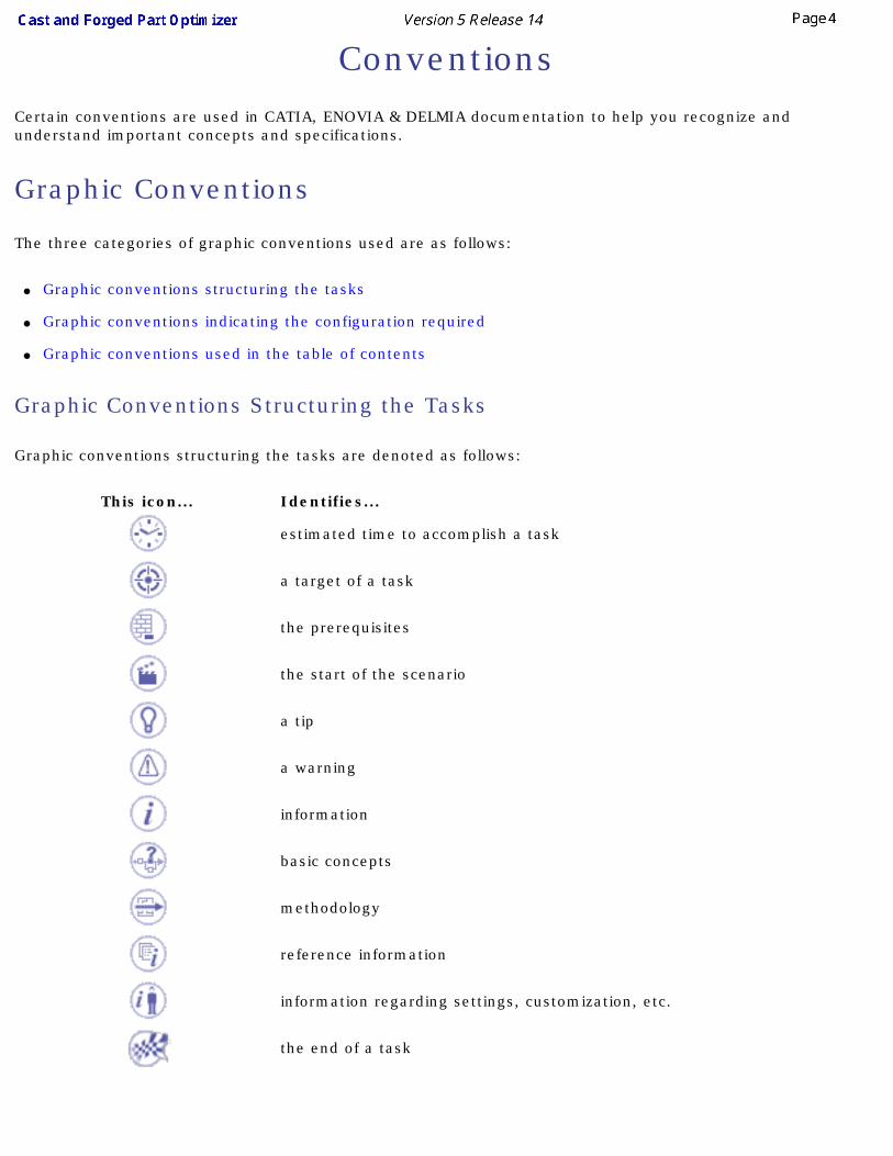
Graphic Conventions Structuring the Tasks
Graphic conventions structuring the tasks are denoted as follows:
This icon... Identifies...
estimated time to accomplish a task
a target of a task
the prerequisites
the start of the scenario
a tip
a warning
information
basic concepts
methodology
reference information
information regarding settings, customization, etc.
the end of a task
functionalities that are new or enhanced with this release
allows you to switch back to the full-window viewing mode
Graphic Conventions Indicating the Configuration Required
Graphic conventions indicating the configuration required are denoted as follows:
This icon... Indicates functions that are...
specific to the P1 configuration
specific to the P2 configuration
specific to the P3 configuration
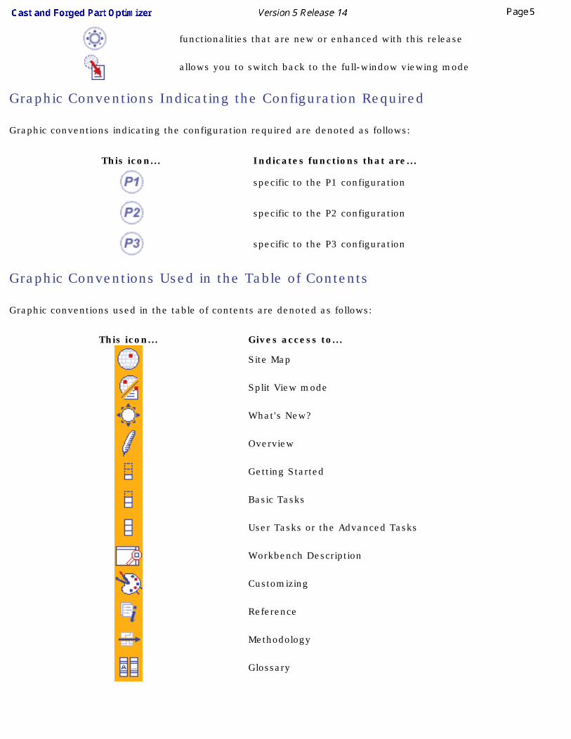
Graphic Conventions Used in the Table of Contents
Graphic conventions used in the table of contents are denoted as follows:
This icon... Gives access to...
Site Map
Split View mode
What's New?
Overview
Getting Started
Basic Tasks
User Tasks or the Advanced Tasks
Workbench Description
Customizing
Reference
Methodology
Glossary
Index
Text Conventions
The following text conventions are used:
● The titles of CATIA, ENOVIA and DELMIA documents appear in this manner throughout the text.
● File -> New identifies the commands to be used.
● Enhancements are identified by a blue-colored background on the text.
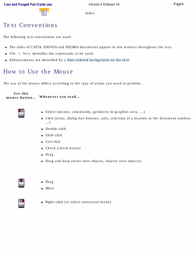
How to Use the Mouse
The use of the mouse differs according to the type of action you need to perform.
Use thismouse button... Whenever you read...
● Select (menus, commands, geometry in graphics area, ...)
● Click (icons, dialog box buttons, tabs, selection of a location in the document window, ...)
● Double-click
● Shift-click
● Ctrl-click
● Check (check boxes)
● Drag
● Drag and drop (icons onto objects, objects onto objects)
● Drag
● Move
● Right-click (to select contextual menu)
Getting Started
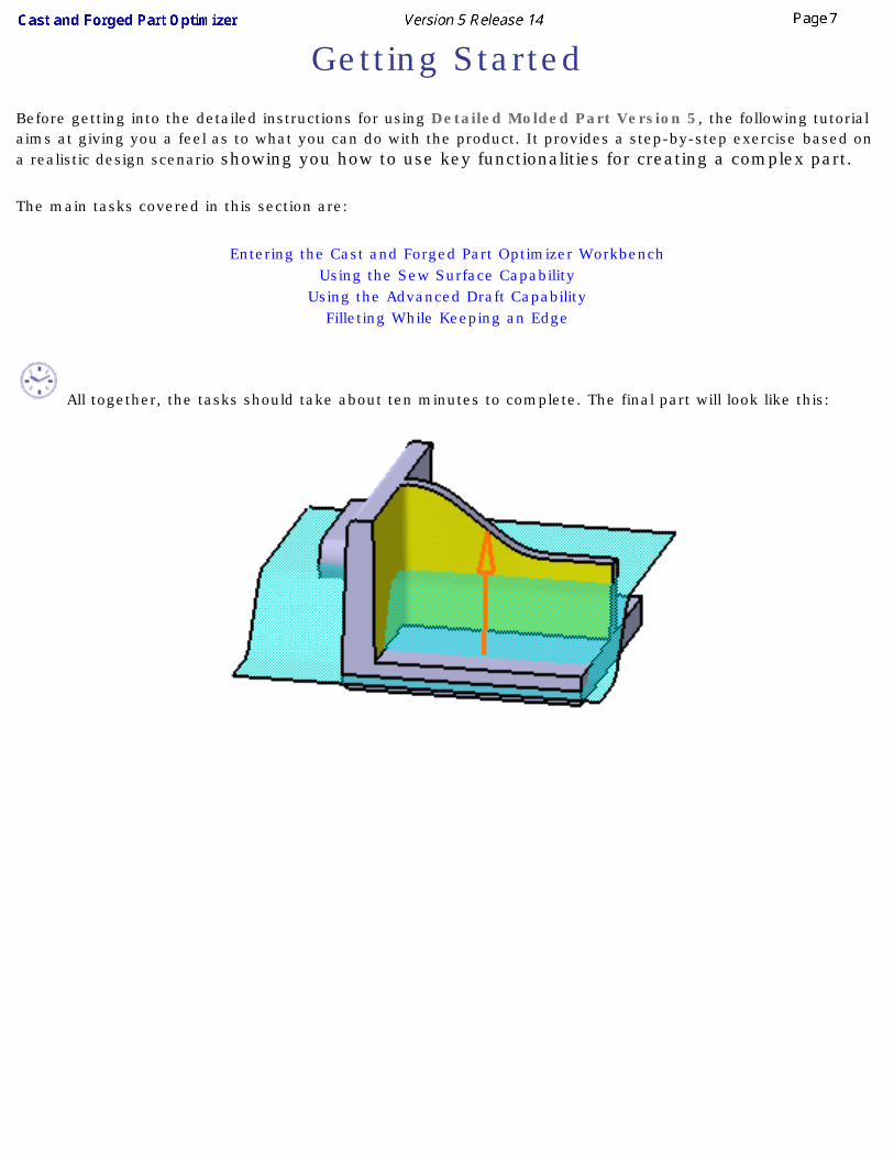
Before getting into the detailed instructions for using Detailed Molded Part Version 5, the following tutorial aims at giving you a feel as to what you can do with the product. It provides a step-by-step exercise based on a realistic design scenario showing you how to use key functionalities for creating a complex part.
The main tasks covered in this section are:
Entering the Cast and Forged Part Optimizer WorkbenchUsing the Sew Surface Capability
Using the Advanced Draft CapabilityFilleting While Keeping an Edge
All together, the tasks should take about ten minutes to complete. The final part will look like this:
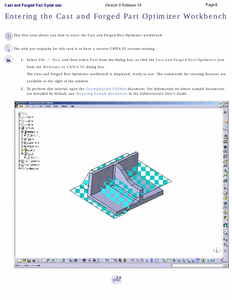
Entering the Cast and Forged Part Optimizer Workbench
This first task shows you how to enter the Cast and Forged Part Optimizer workbench.
The only pre-requisite for this task is to have a current CATIA V5 session running.
1. Select File -> New and then select Part from the dialog box, or click the Cast and Forged Part Optimizer icon
from the Welcome to CATIA V5 dialog box.
The Cast and Forged Part Optimizer workbench is displayed, ready to use. The commands for creating features are
available to the right of the window.
2. To perform this tutorial, open the GettingStarted.CATPart document. For information on where sample documents are installed by default, see Accessing Sample Documents in the Infrastructure User's Guide.
Using the Sew Surface Capability
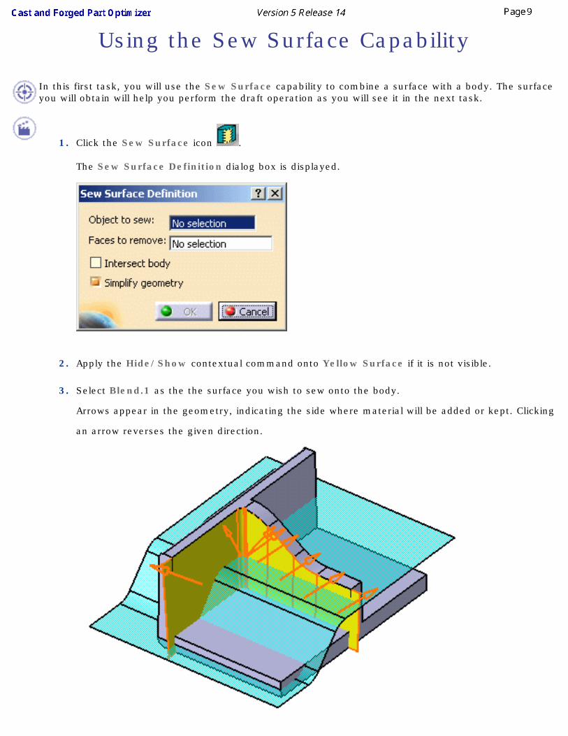
In this first task, you will use the Sew Surface capability to combine a surface with a body. The surface you will obtain will help you perform the draft operation as you will see it in the next task.
1. Click the Sew Surface icon .
The Sew Surface Definition dialog box is displayed.
2. Apply the Hide/Show contextual command onto Yellow Surface if it is not visible.
3. Select Blend.1 as the the surface you wish to sew onto the body.
Arrows appear in the geometry, indicating the side where material will be added or kept. Clicking
an arrow reverses the given direction.
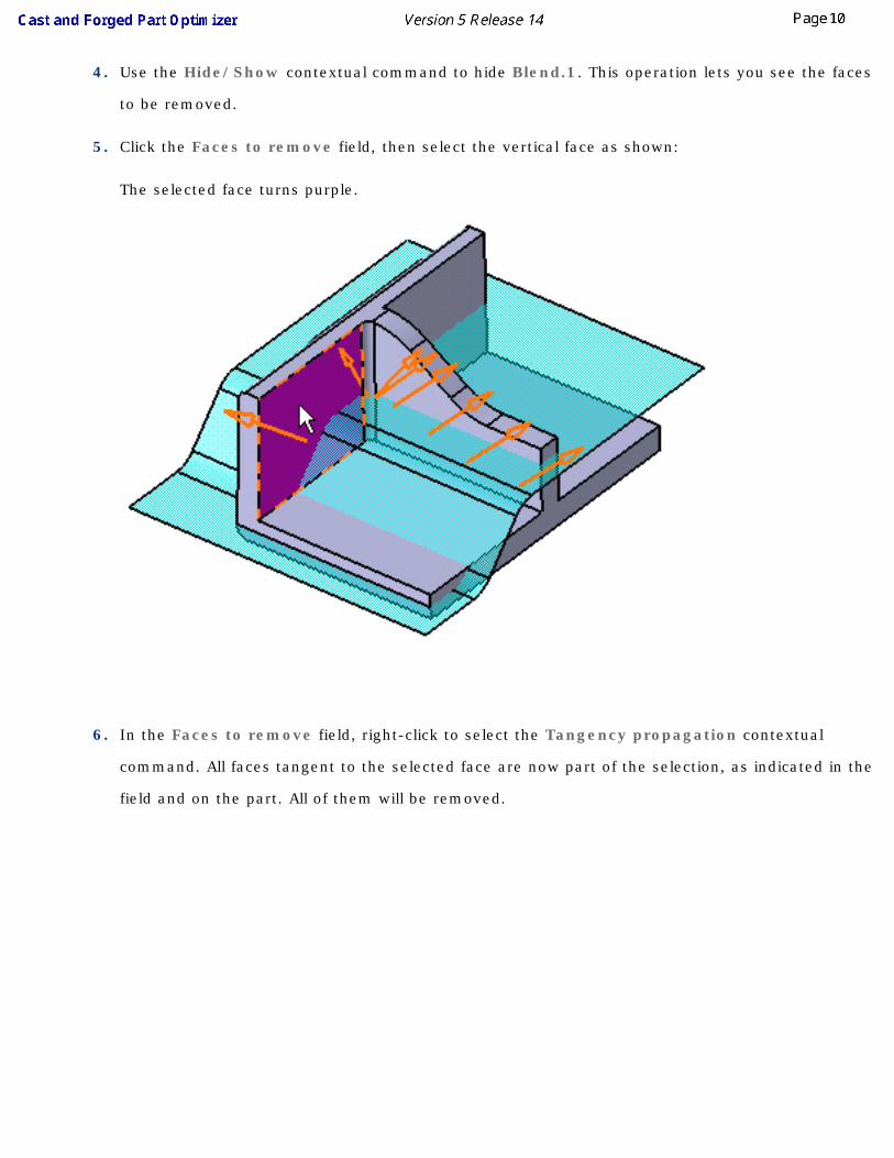
4. Use the Hide/Show contextual command to hide Blend.1. This operation lets you see the faces
to be removed.
5. Click the Faces to remove field, then select the vertical face as shown:
The selected face turns purple.
6. In the Faces to remove field, right-click to select the Tangency propagation contextual
command. All faces tangent to the selected face are now part of the selection, as indicated in the
field and on the part. All of them will be removed.
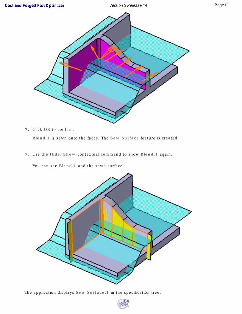
7. Click OK to confirm.
Blend.1 is sewn onto the faces. The Sew Surface feature is created.
7. Use the Hide/Show contextual command to show Blend.1 again.
You can see Blend.1 and the sewn surface.
The application displays Sew Surface.1 in the specification tree.
Using the Advanced Draft Capability
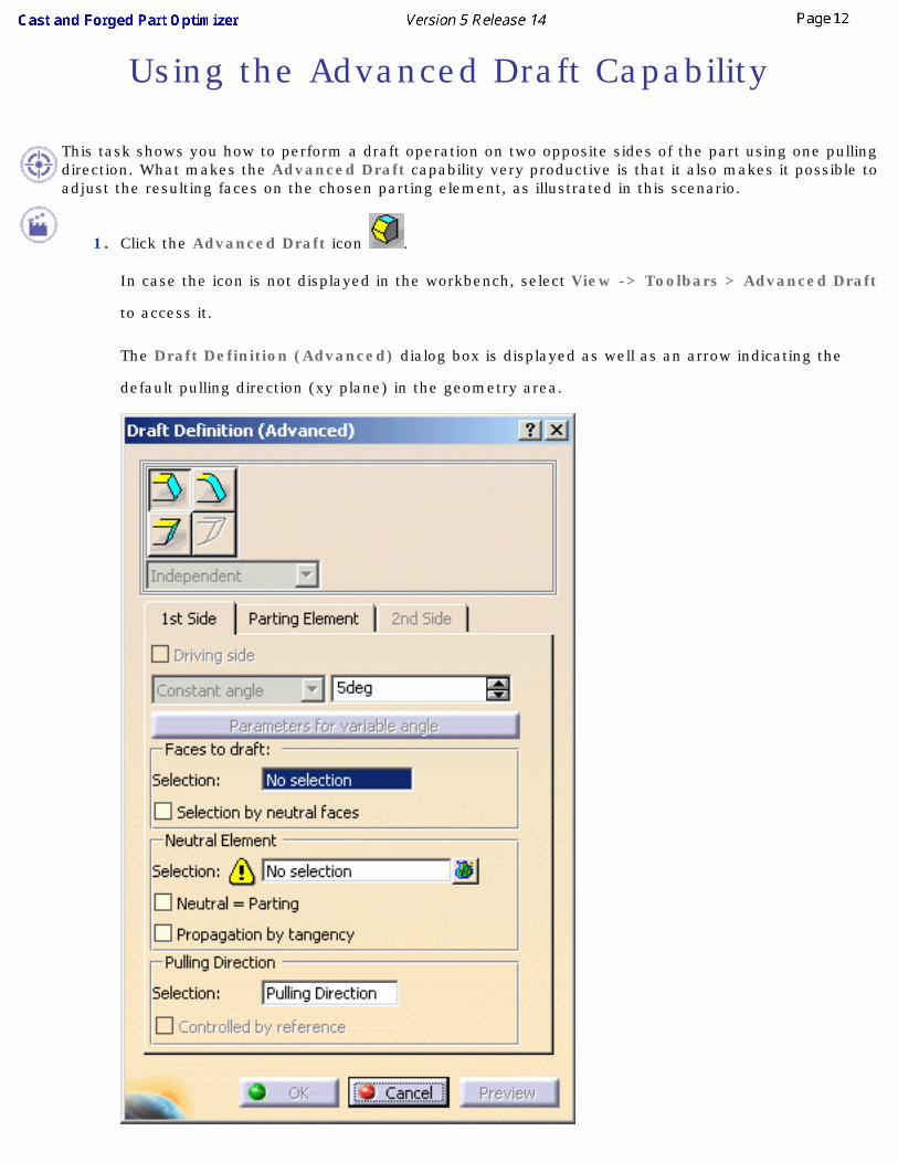
This task shows you how to perform a draft operation on two opposite sides of the part using one pulling direction. What makes the Advanced Draft capability very productive is that it also makes it possible to adjust the resulting faces on the chosen parting element, as illustrated in this scenario.
1. Click the Advanced Draft icon .
In case the icon is not displayed in the workbench, select View -> Toolbars > Advanced Draft
to access it.
The Draft Definition (Advanced) dialog box is displayed as well as an arrow indicating the
default pulling direction (xy plane) in the geometry area.
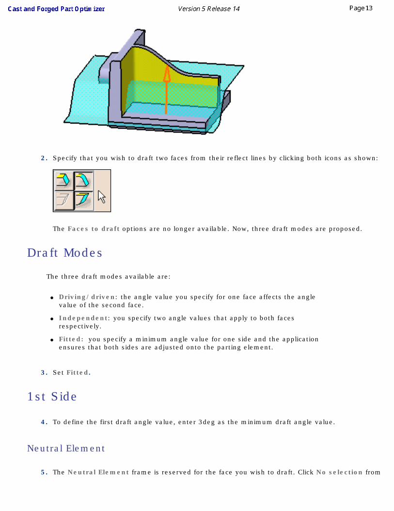
2. Specify that you wish to draft two faces from their reflect lines by clicking both icons as shown:
The Faces to draft options are no longer available. Now, three draft modes are proposed.
Draft Modes
The three draft modes available are:
● Driving/driven: the angle value you specify for one face affects the angle value of the second face.
● Independent: you specify two angle values that apply to both faces respectively.
● Fitted: you specify a minimum angle value for one side and the application ensures that both sides are adjusted onto the parting element.
3. Set Fitted.
1st Side
4. To define the first draft angle value, enter 3deg as the minimum draft angle value.
Neutral Element
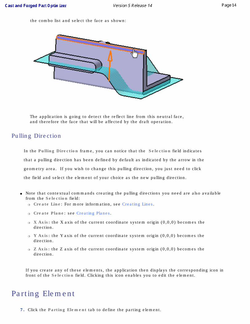
5. The Neutral Element frame is reserved for the face you wish to draft. Click No selection from
the combo list and select the face as shown:
The application is going to detect the reflect line from this neutral face, and therefore the face that will be affected by the draft operation.
Pulling Direction
In the Pulling Direction frame, you can notice that the Selection field indicates
that a pulling direction has been defined by default as indicated by the arrow in the
geometry area. If you wish to change this pulling direction, you just need to click
the field and select the element of your choice as the new pulling direction.
● Note that contextual commands creating the pulling directions you need are also available from the Selection field:
❍ Create Line: For more information, see Creating Lines.
❍ Create Plane: see Creating Planes.
❍ X Axis: the X axis of the current coordinate system origin (0,0,0) becomes the direction.
❍ Y Axis: the Y axis of the current coordinate system origin (0,0,0) becomes the direction.
❍ Z Axis: the Z axis of the current coordinate system origin (0,0,0) becomes the direction.
If you create any of these elements, the application then displays the corresponding icon in front of the Selection field. Clicking this icon enables you to edit the element.
Parting Element
7. Click the Parting Element tab to define the parting element.
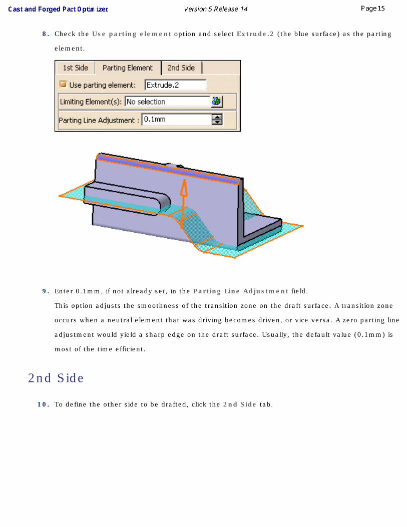
8. Check the Use parting element option and select Extrude.2 (the blue surface) as the parting
element.
9. Enter 0.1mm, if not already set, in the Parting Line Adjustment field.
This option adjusts the smoothness of the transition zone on the draft surface. A transition zone
occurs when a neutral element that was driving becomes driven, or vice versa. A zero parting line
adjustment would yield a sharp edge on the draft surface. Usually, the default value (0.1mm) is
most of the time efficient.
2nd Side
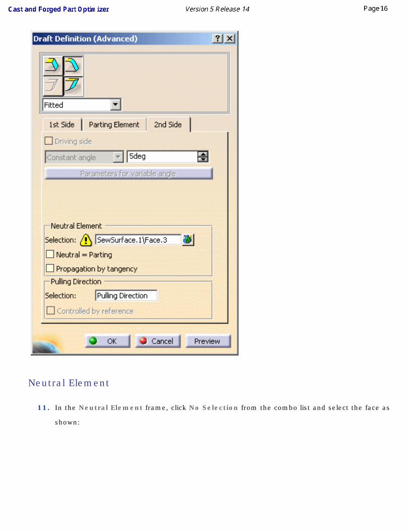
10. To define the other side to be drafted, click the 2nd Side tab.
Neutral Element
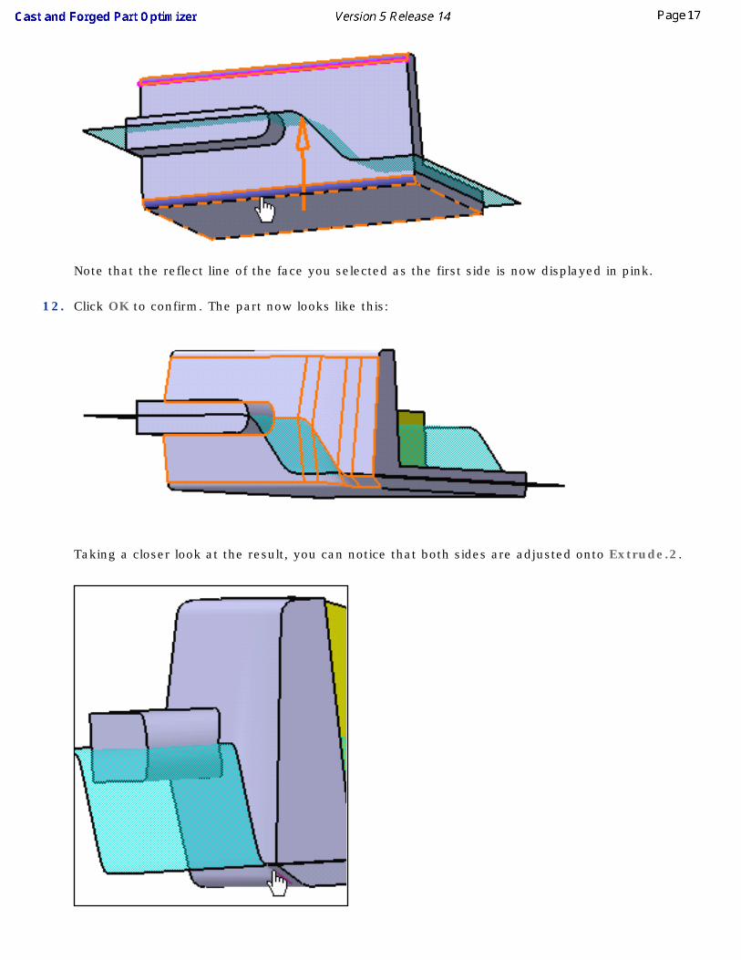
11. In the Neutral Element frame, click No Selection from the combo list and select the face as
shown:
Note that the reflect line of the face you selected as the first side is now displayed in pink.
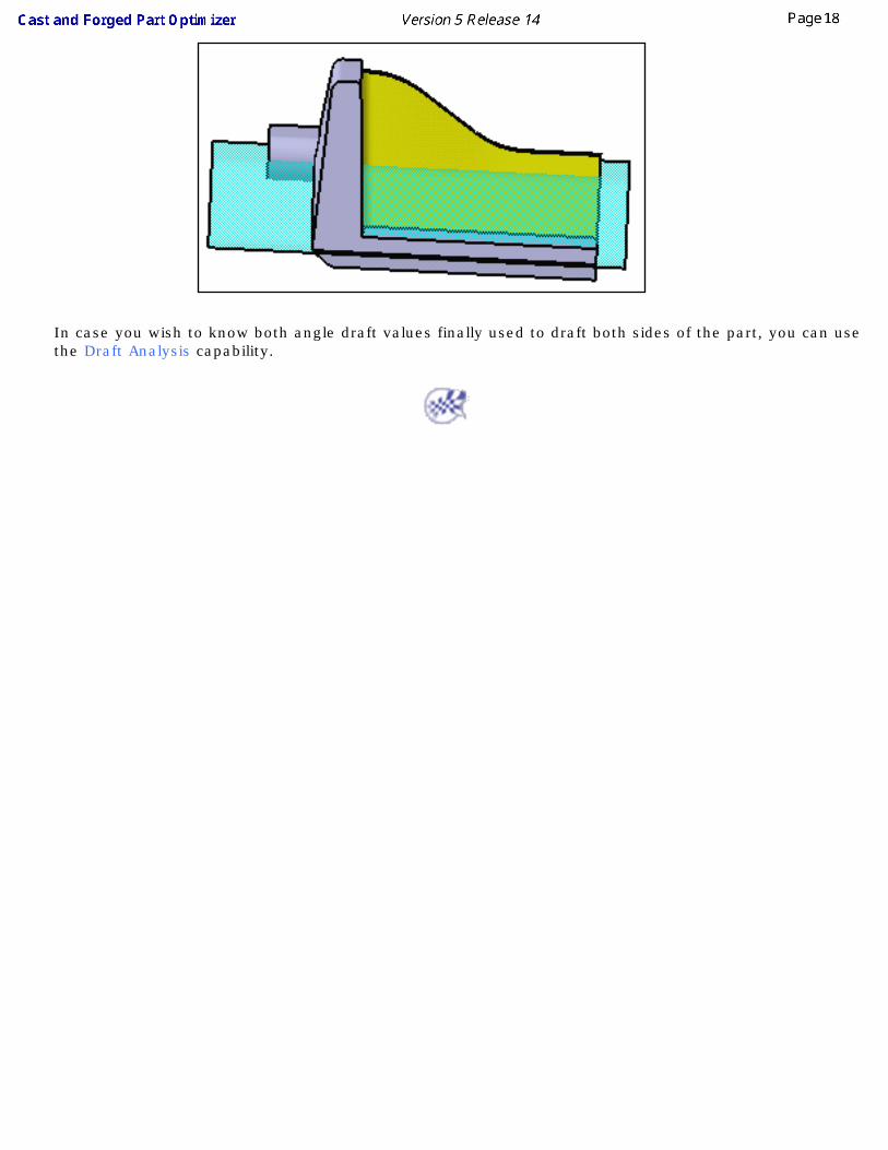
12. Click OK to confirm. The part now looks like this:
Taking a closer look at the result, you can notice that both sides are adjusted onto Extrude.2.
In case you wish to know both angle draft values finally used to draft both sides of the part, you can use the Draft Analysis capability.
Filleting While Keeping an Edge
In this task, you will learn how to fillet an edge using a variable radius value and this without affecting another edge that would have been affected by the fillet operation.
1. Prior to filleting edges, hide Extrude.2 to improve the view.
2. Fillet a first edge to obtain at the end of the scenario a part ready for being removed from molds.
3. Click the Edge Fillet icon .
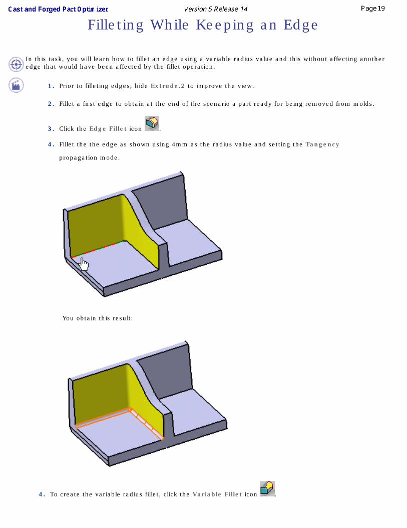
4. Fillet the the edge as shown using 4mm as the radius value and setting the Tangency
propagation mode.
You obtain this result:
4. To create the variable radius fillet, click the Variable Fillet icon .
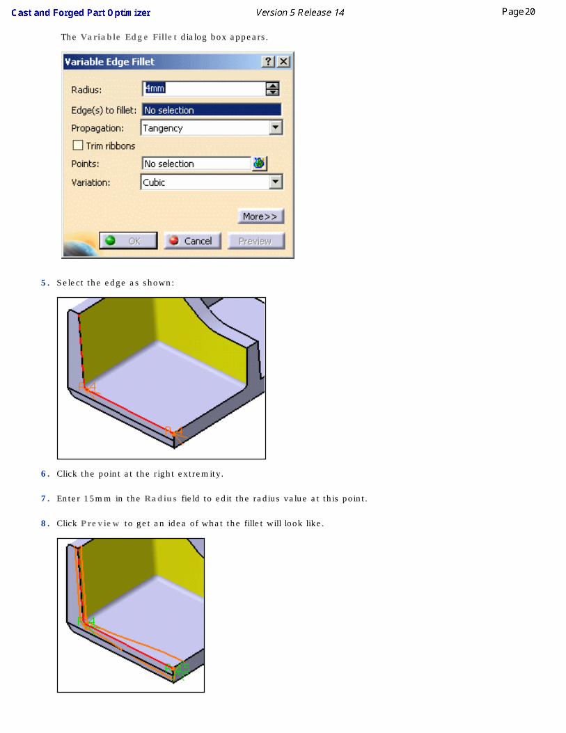
The Variable Edge Fillet dialog box appears.
5. Select the edge as shown:
6. Click the point at the right extremity.
7. Enter 15mm in the Radius field to edit the radius value at this point.
8. Click Preview to get an idea of what the fillet will look like.
9. Click the point at the other extremity.
10. Enter 5mm in the Radius field to edit the radius value at that point.
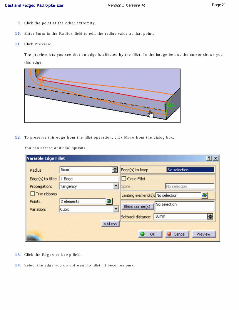
11. Click Preview.
The preview lets you see that an edge is affected by the fillet. In the image below, the cursor shows you
this edge.
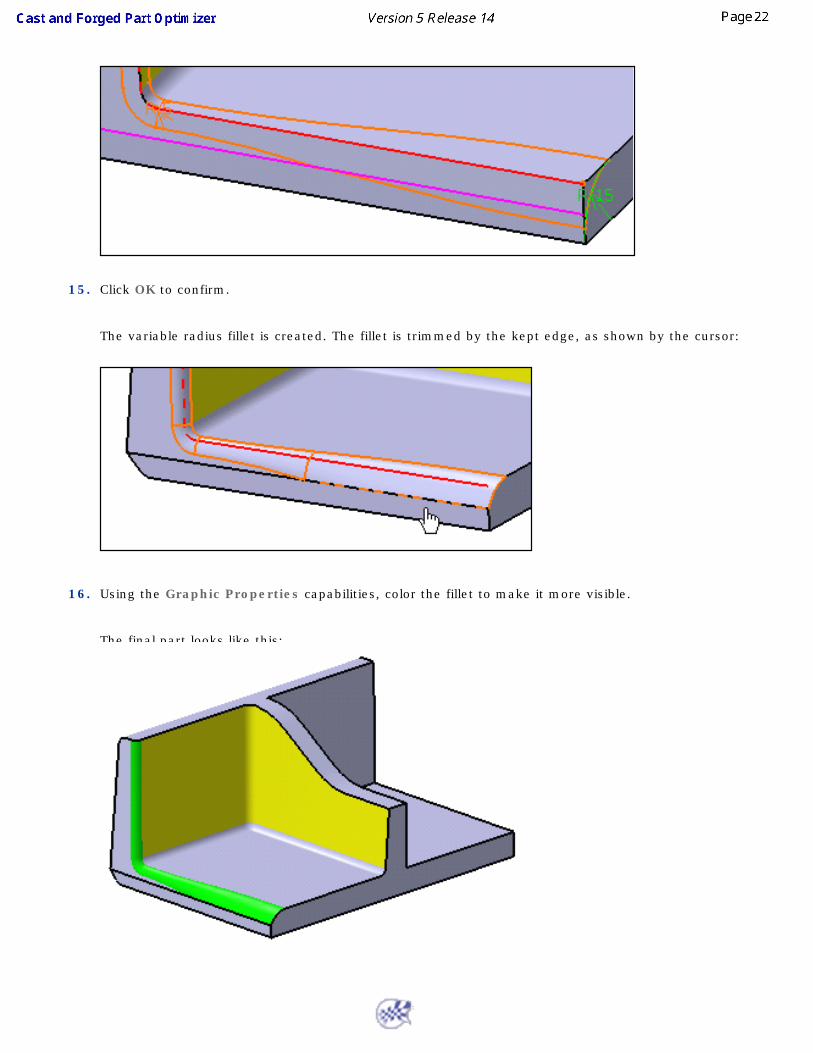
12. To preserve this edge from the fillet operation, click More from the dialog box.
You can access aditional options.
13. Click the Edges to keep field.
14. Select the edge you do not want to fillet. It becomes pink.
15. Click OK to confirm.
The variable radius fillet is created. The fillet is trimmed by the kept edge, as shown by the cursor:
16. Using the Graphic Properties capabilities, color the fillet to make it more visible.
The final part looks like this:
User Tasks
The different commands available in this workbench are described in Part Design User's Guide . They are gathered into two chapters:
● Basic Tasks
● Advanced Tasks
Workbench DescriptionTo access the information on the icons and commands available in Cast and Forged Part Optimizer, refer to the
Workbench Description available in Part Design User's Guide .