17
CAST-IN-PLACE CONCRETE TRAPEZOIDAL MEASURING FLUMES November 1969 ARS 41-155 Agricultural Research Service UNITED STATES DEPARTMENT OF AGRICULTURE

CAST-IN-PLACE CONCRETE
TRAPEZOIDAL MEASURING
FLUMES
November 1969 ARS 41-155
Agricultural Research Service
UNITED STATES DEPARTMENT OF AGRICULTURE

Flume design and operation
Form design
Recommended installation procedure
Operational characteristics
Cost 8
Summary 8
Appendix 9

Cast-In-Place Concrete TrapezoidalMeasuring Flumes
by
James' A. Bondurant ,Allan S. Humpherys; and A. R. Robinson2
Water measurement is an important part of theoperation of an efficient irrigation system. It servesseveral purposes: (1) Assures equitable water distri-bution according to right or need, (2) assures the designflow rate for correct functioning of the farm irrigationsystem, and (3) provides a record of delivery forpayment. Irrigation water is usually measured withmeasuring flumes, weirs, or submerged orifices.
Measuring flumes, such as the Parshall flume, arewidely used and have operational characteristics superiorto those of other methods of water measurement.
Flumes with trapezoidal cross-sections are used to a lesserextent, but they have certain advantages over rectangularflumes. They have less head loss and better trashclearance capability; they can be installed without atransition section since their trapezoidal shape corre-sponds to that of most irrigation ditches; and they areeasily cast in existing slipform concrete-lined ditches.
This report describes the construction and operationof trapezoidal cast-in-place flumes for standard 1-foot-bottom concrete ditches. Flumes of other sizes andcapacities can be installed in the same manner.
FLUME DESIGN AND OPERATION
Standard designs and free-flow discharge tables fortrapezoidal measuring flumes up to 60 cubic feet persecond capacity are available. 3 The flume with a 1-footbottom width and 1:1 sidewall slopes has a flowcapacity from 0.16 to 7.0 cfs. The dimensions of thisflume are given in figure 1. Rating tables for both freeand submerged flow through such a flume are presentedin the Appendix on page 9.
Measuring flumes operating under free-flow condi-tions require only one depth observation for accurateflow measurement. A minimum ditch slope must beexceeded to insure free flow through the flume. At ditchslopes exceeding this minimum, flumes can be installeddirectly on the ditch bottom with the invert serving asthe flume floor. Since many concrete irrigation ditches
Contribution from the Northwest Branch, Soil and WaterConservation Research Division, Agricultural Research Service,USDA; Idaho Agricultural Experiment Station cooperating.
2 Agricultural Engineers, Northwest Branch, Snake RiverConservation Research Center, Kimberly, Idaho 83341.
3 Robinson, A. R. Water measurement in small irrigationchannels using trapezoidal flumes. Trans. ASAE 9(3): 382 .385,388. 1966.
Robinson, A. R. Trapezoidal flumes for irrigation channels.U. S. Department of Agriculture, ARS-SWC, ARS 41-140, March1968.
have less than this minimum slope, the floor of mostflumes must be raised above the ditch invert to providefree flow. Flumes normally need to be raised only theamount required to assure free flow, thus minimizingfreeboard and conserving elevation head. Elevatingflumes more than the free-flow elevation results inunnecessary head loss and excessive turbulence down-stream.
Arrnrate flow measurement with a sinale depthobservation is assured if submervenre does not aced75 percent (free-flow condition). Free-flow conditionswill exist if the flume is raised an amount equal to thedifference between the normal downstream depth and0.75 h 1 . The normal downstream depth can be deter-mined by observing the existing design flow or by usingfigure 2. Recommended free-flow elevations can bedetermined from figure 3. If the flume is installed on thebottom of the ditch, the slope required for free flow isgiven in figure 3 at 462 = 0.
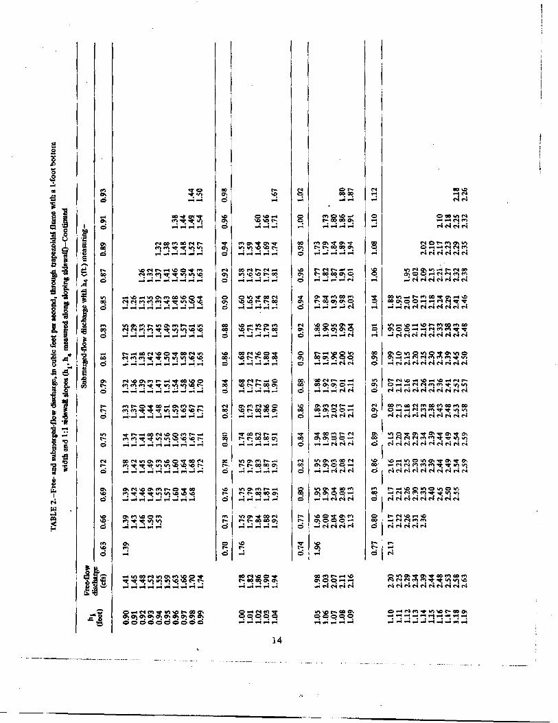
Because a relatively small head loss is required, mosttrapezoidal flumes can be designed for free-flow condi-tiOns. For submerged-flow conditions, a staff gage isrequired at the downstream (h4 ) location as shown infigure 1. Flow depths at both locations are observed andthe discharge determined from the submerged-flow
1

5
a_
a

`1A01A AO 111.c130
Se;
1
6O
TI
O
. 5
ay
3

E000
•gio . 0 U Nava ?nap pue soda's snogen ZE mou earj JOJ uogsnafa aumil 'E unR/H
14 ei3d ld r3c1015 13 N N VH 3
ZO0'0 I00'Ci 9000'0 .0000"0 Z,000.00
0 rn
c
rn
rnrrn
• 211.0z
0
'0
0
hShilh 4 4 01014
It
i
I
44 I h h ,-111‘‘
s02.9‘
"1J
kli i g k. 1111\1 ‘1
iiiiI
-.
4,1,p21000D
CZ V *02 =
=:al
I
ZV0Sdtup x 3

tables. For best accuracy, flumes should not be operatedat submergences greater than 95%.
Trapezoidal flumes convert subcritical flow in theapproach section to critical flow in the throat; therefore,the velocity immediately upstream must be subcritical.If the velocity is supercritical, the backwater depthabove a flume installed on the ditch bottom may not begreat enough to create a hydraulic jump upstream fromthe flume. In this case the flume should be elevated toaccomplish the conversion to subcritical velocity. Figure
2 may be used to determine whether the normal flowvelocity is critical or supercritical.
The flow should approach the flume in a straight pathand should be reasonably smooth and uniformly dis-tributed across the width and depth of the approachchannel. Flow to be measured should be relatively freefrom turbulence and eddies such as might occur below acontrol gate. The flow pattern should be observed beforeinstalling a flume in an existing ditch, especially if theflume is to be installed near an object that would createa flow disturbance.
FORM DESIGN
The form for casting flumes in concrete-lined ditcheswas made with an angle iron frame covered with3/16-inch sheet metal, figure 4. The outside dimensionscorresponded to the inside dimensions of the flume infigure 1. The frame was cross braced on the interior and
Figure 4. Form without the removable approach section forcasting trapezoidal flumes. The ditch invert served as thebottom of the flume in this installation.
across the ends to give rigidity and resistance to torsionstresses. If only a small number of flumes are to beinstalled, a lighter form, constructed from plywood, ischeaper and may be satisfactory.
All joints were mitered and ground to obtain sharpintersections in the castings. The form was made with aremovable section on the approach end. Each end had anadjustable end plate so that the elevation of the flumeabove the bottom of the ditch could be changed asrequired for free flow. The approach section, end plates,and a removable bottom were used when a flume wasinstalled with a raised floor. When the flume was castdirectly on the bottom of the ditch, the end plates andthe bottom were removed and the invert of the existingditch served as the bottom of the finished flume,
Angle iron clips were welded onto the end plates sothat the form could be clamped in place. Holes, drilledin the adjustable end plates, permitted raising the flumeform by 3/8-inch increments. Dummy staff gages ofstrap iron were attached to the under side of the form atboth the upstream (h 1 ) and downstream (h4 ) gagelocations to form recesses in the concrete for standardgages. This permitted staff gages to be installed flushwith the flume surface. The downstream dummy gagecould be removed if only one gage was required.
RECOMMENDED INSTALLATION PROCEDURE
The ditch section selected for installation of theflume should be of sound concrete. Cracked sections andareas where frost damage may occur should be avoided.After the site for the cast-in-place flume is selected, itshould be thoroughly cleaned to obtain a good bondbetween the existing concrete and the cast flume.Cleaning while water is flowing in the ditch helps removesediment from the bottom of the ditch. A wire brush
will usually remove moss and dirt accumulations on theconcrete as well as any loose cement particles that wouldinterfere with the bonding. Most slipform concreteditches have a sufficiently rough surface so thatscarifying is not required to obtain a good bond.
After the ditch section has been cleaned, the form isfitted to the ditch. A steel pipe tripod and a chain hoistcan be used for raising and lowering the form (fig. 5).
5

Figure 5. Form in place for casting a flume with a raisedbottom. Note end extension section, tripod and chainhoist for handling the form, and "C" clamps which securethe form to existing lining.
After the form has been centered in the ditch, it isleveled in two directions by chipping concrete fromunder the contact points, by shimming under theadjustable end plates, or by end plate adjustment. If theform is set directly on the bottom of the ditch, a goodfit is essential, particularly in the throat section. Thismay require considerable work unless a smooth sectionof lining is selected for the installation.
After the form has been leveled, it is clamped to theexisting ditch lining with large "C" clamps. The clampsshould be tightened at approximately the same rate onall four corners so that the form is not warped. The formmay not fit the sides of the ditch exactly, since someconcrete slipform ditches have slightly flatter side slopesthan the specified 1:1.
The maximum aggregate size that can be useddepends on the elevation of the flume above the floor ofthe existing ditch. If the form is placed directly on thelining invert, the ends fit against the ditch, and both theupstream and downstream ends of the casting are feather
edged. This requires a fine sand aggregate and moreslump than a flume cast with a raised bottom. Largersize of aggregate can be used if the flume is elevatedabove the bottom of the ditch. In general, the maximumaggregate size should be about 1/2 the minimumclearance between the form and the sides of the ditchlining so that concrete may be readily forced underneaththe form. All aggregate and water should be clean andfree from dirt and organic material.
Type 2 (low alkali) cement is recommended. Air-entrained concrete should be used where freezing andthawing occur. The concrete mix can be batched byvolume measurement with a cement content of aboutfive bags per cubic yard. To insure adequate strength, arelatively dry mix should be used. A 3-inch slump isneeded for concrete that is forced under the bottom ofthe form, but a 2-inch slump is adequate for the balanceof the pour. When the flume is to be poured directly onthe floor of the ditch, the amount of concrete requiredwill vary from 3 to 4 cubic feet, depending on the depthof the ditch. When cast with a raised bottom and theadded approach section, the amount of concreterequired increases about one cubic foot for each 3/4inch of elevation. For example, a flume cast with a 11/2-inch raised bottom will require about 6 cubic feet,and one cast with a 2 1/4-inch raised bottom will requireabout 7 cubic feet of concrete.
When the form has been leveled and securely clampedto the ditch lining, the flume is ready to be poured. Forgood bonding, it is advisable to wet the surface of theconcrete ditch before pouring the concrete. Flumesinstalled with a raised bottom should be poured fromone side until the concrete has been forced under theentire bottom section to eliminate voids under the form.After concrete has completely filled the bottom section,the flume may be poured from either side of the form.The concrete should be well rodded to prevent voidseither against the concrete ditch or against the form. Anelectric-impact hammer can be used on the inside of theform to vibrate the concrete. After the concrete hasbeen placed, the top surface edges are finished bytroweling. A flume cast directly on the bottom of theditch is shown in figure 6, and an elevated flume isshown in figure 7.
The length of time the form must be left in placedepends on climatic conditions. In hot weather theconcrete may set sufficiently in one hour to allow theform to be pulled, whereas in cold weather it may benecessary to wait overnight before removing the form.Considerable care must be exercised if the form isremoved before the concrete is hard. The hoist used tolift the form must be accurately centered so that theform can be lifted vertically instead of at an angle. When
6

Figure 6. Cast trapezoidal flume using the ditch invert as theflume bottom.
Figure 7. Trapezoidal measuring flumes with a raised bottomcast in a concrete ditch.
the flume is cast with a raised bottom, the end platesmust be removed before the form is lifted to preventdamage to the ends of the casting. A well-oiled form
makes removal easier, particularly if it must be removedbefore the concrete is fully hardened.
When the form is removed shortly after initial set, theconcrete can be troweled to give a smooth surface;however, troweling at this stage may change the flumethroat dimensions. The form should be left in place untilthe concrete is hard enough to insure that dimensionswill not change when the flume is being finished. Cast
flumes left long enough to preclude troweling of thesurface usually are smooth enough that the flowcharacteristics of the flume are not affected. Small voidscan be filled with a fine sand-cement mix or a neatcement mixture. Small ridges can be removed with atrowel. If the concrete has set for several days or longer,a carborundum block is needed for smoothing ridges. Acuring compound should be applied to the finishedcasting, or it should be kept moist for 3 to 5 days. Agarden type sprayer can be used to apply the curingcompound.
In cold weather, precautions should be taken toprevent the freshly cast concrete from freezing. Theditch lining on which the flume is cast should be abovefreezing temperature at the time of installation. It maybe necessary to add calcium chloride to the concrete mixand, if possible, heat the aggregate and water. Thecasting can be adequately protected by covering with atarp and loosely piled hay or straw. It is advisable toprotect the concrete from freezing for at least threedays.
Staff gages may be cemented to the flume sidewallwith a waterproof cement or attached with lead anchorsand screws. If they are cemented, wax-type curing agentsmust be removed from the gage area. The gage should beplaced exactly at a 45° angle with the bottom so thatdepth measurements are indicated accurately for deter-mining flow rates. Conventional, enameled-iron staffgages, 2 1 /2 inches wide, can be used.
OPERATIONAL CHARACTERISTICS
Visual observations of the flow pattern through castflumes have been made. Differences in flow patternbetween flumes due to sidewall roughness were minor,although it appeared that the most uniform flow wasobtained where the form was not removed until the
concrete was well set. Those flumes from which theform was removed while the concrete was still greenenough to trowel finish appeared to have slight varia-tions in the flow pattern. No visible differences wereobserved when the abrupt elevation change at the
7
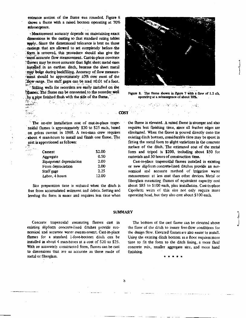
entrance section of the flume was rounded. Figure 8shows a flume with a raised bottom operating at 70%submergence.
Measurement accuracy depends on maintaining exactdimensions in the casting so that standard rating tablesapply—Since the dimensional tolerance is best on thosecastings. that are allowed to set completely before, the
',form is removed, this procedure should also give the-1/110staccurate flovi measurement. Cast-in-place concreteillumes may be more accurate than light sheet metal onesinstated an earthen ditch, because the sheet metal
- bulge during backfilling. Accuracy of flow measure-nent should be approxiMately ±3% over most of the
aloiv range. The staff gages can be read 4.01 of a foot.
Stilling wells for recorders are easily installed on theflumes ,The flume can be connected , to the recorder Well4by t pipe finished flush with the side of the flume.'
•Figure 8. The flume shown in figure 7 with a flow of 1.2 cfs,
operating at a submergence of about 70%.
The on-site installation cost of cast-in-place trape-zoidal flumes is approximately $20 to $25 each, basedon prices current in 1968. A two-man crew requiresabout 4 man-hours to install and finish one flume. Thecoat is apportioned as follows:
Cement $2.00Aggregate 0.50Equipment depreciation 2.00Form depreciation 2.00Staff gage 2.25Labor, 4 hours 12.00
Site preparation time is reduced when the ditch isfree from accumulated sediment and debris. Setting andleveling the form is easier and requires less time when
the flume is elevated. A raised flume is stronger and alsorequires less finishing time, since all feather edges areeliminated. When the flume is poured directly onto theexisting ditch bottom, considerable time may be spent infitting the metal form to slight variations in the concretesurface of the ditch. The estimated cost of the metalform and tripod is $200, including about $50 formaterials and 30 hours of construction time.
Cast-in-place trapezoidal flumes installed in existingor new slipform concrete-lined ditches provide an eco-nomical and accurate method of irrigation watermeasurement at less cost than other devices. Metal orfiberglass measuring flumes of equivalent capacity costabout $85 to $100 each, plus installation. Cast-in-placeCipolletti weirs of this size not only require moreoperating head, but they also cost about $100 each.
SUMMARY
Concrete trapezoidal measuring flumes cast inexisting slipform concrete-lined ditches provide eco-nomical and accurate water measurement. Cast-in-placeflumes for a standard 1-foot-bottom ditch can beinstalled in about 4 man-hours at a cost of $20 to $25.With an accurately constructed form, flumes can be castto dimensions that are as accurate as those made ofmetal or fiberglass.
The bottom of the cast flume can be elevated abovethe floor of the ditch to insure free-flow conditions forthe design flow. Elevated flumes are also easier to install.Using the existing ditch bottom as a floor requires moretime to fit the form to the ditch lining, a more fluidconcrete mix, smaller aggregate size, and more handfinishing.
8

Ww
ev one/ r-°° °'? 01 a:
• mo 0 r- ./• co °I on.
co
CD 41 a, 470 eta:. C4(71 ITO; CD
0
ce. nn Ch MN.- 41 m un41411 A A Ce: CIS CD C70 .4 .4
on mr on A co mk 0 • 0 05 NAvg 00 00 Cr: Cr C7 C7CD 1.nn
47 CO C, er o- on v7 eo mr 00r4 vp
41 41 41 41 r: r: °I °I c1 cl1 '2' 21
o M 00 "ere, on s.0 •r?
41 41 4n 47 47 47 e-7 1..:ol cc! oi Ce: on0
Nun co on vo co rq ti p en IN C7 M n4r 41 41 41 4:!'"P (": t"; °I 00 00
0
gt,,,r .3. 05 wm rk n cD on r-
T yr. 41: 41: 41 4.741m 47cp.
mr r- eo mr AC?, 01 4550 .4 mr
r1 .1. 'E 4t't 41 41 41 41 41 41
e- mr co MmO.M r1 rl '14 41 41 41 41G
op ro en unto w4 01 ka .tiN encl ol ,r ,r0
4 7 r- CD e/ /r CO .4 ,r \ID
NN rn rn on on /3. me. Tr0
N kt n00 on wn r- Cr,N N on on on ono-,. . . • . . .
04 10 47 05 en .4 01
rl r4 N N N[ ol
M et .41, CON N e4 el el
0
▪ C-- CO ON en— 1.4 1. N N N• • • • •6‘13 Co Ch.1.• 1,1 4.
kJ:J. CC SON en N N NN 00 CR 4.-.1 on un r- cn ,r ,r vg cs, un co cc, CO* ey Le) en m r-
el el eal rl el el el 01 re! ol m.,/r mr. 4n un 41 A vp A A r-.7 e- e- co co co on. on co
1.4 C9 M'7 un 1- 00 ph M C un 1O 10* rq 141 ,v Ul r-C° Ch 0.+ rq M mr 4 .45N clog NNNN NN N on on en en rn rn 01 rn On mr sr ,r 11. .7. '51- 40 el. mr R 4/ 41 41 41 41 VI6066666006 66 e 66666 6666066666 0666666
Net
go
O
6
N
6
co
goN
NO
•cr
0
NN
coN
OO
E0
Ia
3 '10
g
I .E
a.d
•
E.; 8
e
3 900
010 .fir
LL
4 6
9

S.
O
7.
00cod
00
N
r-;O
oosO
'60
Ca
Ncon
0
wr-unmor- onvvznwenod NNen414,44f-iN eir4e4
1A s0N000 00.-4 NNM(.4(.4,4
7100nN000.O en C7 .0 mom=4.4
unrama,Naov–ir- de.m. . NNN rielN
wmraNnmer...rft..e onvmemm.
.tiN NN NNN
22 n .
.11.-1.-4r-mms0N00wl Nmw;s0 n oo co en ono,-, C•4! eninv..4,44 .. 4.4 (.4e4Nr4
c; v: cS°9 –:
.-1 O- cr.00nORo.m
.t050.-1r-mm ,.0N00 .^NooC--00000.12.100,-.Nr4.4.4.4.4.4 e4 r4 r4 r4 NNN
CI .4 N env In 00 01 0.--105e-r, r- r- r-r- e. r- r, 00000o tod666dddddd dod
Nrcar,
NN
1/42 CC: 01 0NNNen
.0 n00 n n1Cn wt r.
mverRtmNr-mr in %a. r-; 00.. en CD •4r4raei Nr4 f4 r4 In
NN.kochtem-NNoer..ten,z,nr-cno.-INNe-i N e4 N riNviceiri
NNNNN NN NNen en In
nunmap ..omeNcomvqr,-4NN.-4,4N1.
.-lyNOW%0M.mICAyMPNn44. ...1 .410424ONI-1NenNr4r4NN4Nriesieit4r4
Or“re404e..N900rn"..94:!,..:41n1r4O1Nelere4Nrgrier;e4
1.1 0310 M =WI M in en
NI PI NNNNN Mm 0-1 MM
,le.4e4e4(.4m,4,4,4,4
.. 00 koINOnoneta .-Lnn1On0000O. o -+r.iriNe4NNNr4e4
.10OUnr10W
Noo040
VINOC-4 .4. NCINN. waMNCr,w1 .01101,=0.4/4ammNe4NNNNNeviteri
mertmanoochOo.INmnt00 00 000000 00000007,6666666ddddd
O
Ap
ti
0 0
Ji;
11
1 81'.
OE
wa
r
A
e-c;
N
c;
00
‘ci
"4:
NVO.
O
00
O
•or
.-1 00
Nal%oNMeeiekn
n.oNtmel. m0N .4. 0wN earn erSIn.O
.
Ne-.410w10704o9R%0cA pp .-1..irimmerViraw%4• • • • • • • • • •
4 11N - INN nn-tn ,R
Li g;ei0 ';I
•••'
Schen co rn —i wn O wnON .4044Menerwritliel%0W
5 :4
11an 4nOo•r riv)•-I‘O.4%to• ,. NNNM4rne
g6O
Cft VT 00 N (--C4 VO UD
4
O oy oy on on et ne
omrec ene-NNegre,.4,44 –1,44
N 04rM
O .1n1
n•nI
N‘a0 vmetwmcomcorelo,r4NenenVVICIW
.4.4.4 .4.4.4 .4.4 .4.4.4.4.4 .4 .4.4
N00 cn N N In mr n mar- 00 0.gal n 4-1 4? Nq ‘0. '4:: 47 4D
14.1 ddd diddoddoodd
10
as=,r4
CO. CC, t"...CO Ch 0.r
NNN
..nNNN

un .0 unch e4 n as in1 "1'4: ci! c?
•r 4t 4r .rerttlitn 47
r- .4 on in F.. GIN 41 V, CI .4Olmt 47. 01 .0 Nenmr mt mr mr mimr 44 .44N
▪ ec ch en un g OD CD onone} 4n GC: CI .4 CM et 41'a 'a milt mt in ui in 'n 'n
0 At nUP GO C. CD V4 en onAt Oi cp [41 on mv. 41
3 4 It mr ' iviin in
VP N GO chez, .4 r4 mr un .4eel 47 r- GO 0 mw N 01 mr.mr mr mi in in 47 67 47 in
Cr, 0, ." C4 en eh Ch e4 enun UR OP Cs 0.0 r4 At 4D• ev 444444 474747
.4 f0 07 v- GO en ow V4 Atkr! GO e4 ul •4R t-mr 4 'a 4n 45 UN 4.) 414,4
en en V? V- CO Ch CD N On 47o -1 N .4 in
4 4 mr mi ui vi 47 W7
01 0 I-I en 4e-• cocnc::-n Ti! W-4 mi Tr %, 44 vivnun i.i
r- oo en en CD ...I N mrr. 00 Crt Cp Nen At .41 uR r-• 4. mr un 44 44 un unvi
CO Ch en 0 .4 C4 CN Vt Sc c-r. oo en r4 en mt ve o,mi 4 4 Lti 4i 44 4144 vivi
CAC, CD eo r4 on unn- el': CD ...I el 01 yi▪ mr ui vi un ununu,
CD CD eA N NCO Ch Noi mi vi mi mi
a -1GO C1.1. .4-
GO 0000 Cs 0 ri
11
Ch en et leVA tn 00vt; 4i vi un ton vitt.; mi
e5eo N en yr un 46NSc CO Ch
Ch 4n CD 'aGO Nn SO Ch eneA Mn UR rl 0)0 el At UR44 4n On 474n 4747 47 %047
Ch en t, C7 en enod
A Chen ADei eel O OI 41 47• un 4n 4141464i Sc 42 LD
MD ChNeA on v2 CFI r4 42 Chon mi.. ie! eh C?•-.4 Vim} 41 4:244 4141 44 4) Sc "0 Sc v3 y>
ch 1r r'. Ch re 41 CC .4▪ Sc oi or. a .4 el ms: r-u, 414744 %D 4D vDmDmo
*el et r-oortimr r- CD CDSc DO en ON col mr. ul en41 47444n Ai LD Sc AD 42 keD
en 41 on 4-0 mr on vp%or; 00 Ct .4 ci ul se! v.: 121,444744 41 47 47 42 4D 47 47
WI Cri chr4Are...cDenuor-oR ON mr 4147 GO as44 44 47 vS 4:3 up ke;miuiuS
N 8 GO .4 en v2 00 ...1z4R 171 "dl?". v1 4? 69_,v+ '543 ,4 Sc Sc Sc %A 417
n1 41 r- r4 r- CD r4 unOD°, CD eo en At ri oe ehwi N USA:. Ai AD ADAC. Uiu6
in io co rn le) Op n,-n tn.oi r4 en 4 r- o2
4n4ivo4iv540 %ovi vivD
CSC r- ON erLDCheA .V
CC OS one} cop,in in y> Sc mS Sc m3 ,4; ve,
r, 02 CDC-4 Nnt-- ON WIGO Cileor4 en Mt 4R r- oovimnvivS u5 up mo v5 u6
▪ CN l•q en in DoCe al .4 C0 VN mt.
wi in 4p kJ:3 Sc
CO O Nas+ 0! -1SD ,
• Ch ...men 41 C.. CD ON 41E0010 Nen et rn C..00 01CDui u6 u$ 45 4D Mi %i U$ 4O
CD eA N en 'a 41 4qt... 9Q ChNei N N N N N N N N
N
CO
Cs
N
Ct6
CO
Sc
0
a
NGO
00
00C-C;
6
Nrr
4N
GO
Sc
C
NCr1
O
Ocoa
CO0
4
11
N0
01 a% -VI
en e; -4: 4
Sc 00 ch .--1 r4V- •.4 ersr-Ch
• r4 or; 4
oM in r, Ch 4 .. N 414147 V, 00 v-1 ol mv.04 04 or; 04 mi
N VD en ow On mt st un r•-• CON en es. AR r+ go Cm CD ri 01on to; oi on 040404 mr *et ,*
02 ,r up r- le. CO OD CN Ch CD CD CDCD el en et 41%0 e+ Ce, 0 01 Nt y1et; e4 oi on on cri cri rei m; mi mr mr
CO ON 03 ..... N N r4C. O •-o en Ai- un AR co Cs cR 4 inN er; re; en re; ce; en re; on mr 4 4 mi
insptOtD WI .41 ..... C•1 en st4 I-4 Nmr. r-+ CO Ch Nej: %C!el to; oi to; on on to; 04 or; mimim;mimr mr
.. .4 CD Ch CO tit, 404747 47 4742V- r-eA Nen et WI up r- oo ch a .4 rl ul uR
Pei eel rri en or; mr mr mr mr mt
nt on +
V4 .n CD cm eh 00 r, co v, v...0*,20oq en mr tra yp UD O0 CN .4 fl en * 41 up
oi •i on erier; m; mi mt mr
v, ea om CD g? gD en eft 00 00 CA 0%C11 lei .4. n .0. GI 9nI eqat-n.i.:n4 n4 v4 vi oi on on 4 4 44 4 ..
GO Nn on ov .0 .0 CD CD en eh en eh CDNon mi. 47 V, 0001C.. .4 C0 NI on et 47Nre; re; re; er; en' re; en it 4 4 4 4 4 4 4
CD 00 VO vn As. en C4 r4 eA eA CD CD cD cDon on im VD N op Cr. CD e* r4 Onmi.. 4n 47 V-on; rf; o4 G4 re; re; 4 44 4 4 4
on en e4 m in .4c2 r- 7 010 .-4 el en et VI n.0.WI on on on e4 c4 oi mrmi mi 4 mrmr
CD CA CC un mr mr on r4 r4 .0et 0t 4747 r- OD at C]eAr4 onoioi o4 eei oi mi mi
eA CD 00 %n mr on▪ on Vp V, o2 on CDei en ei el n4 .4 0,7
r4 CD Cr, 02 r, 47.tt 41 47 47 V- ODpi pi pi pi pi pi
0iv inr, on of
r.urp un en r4 04 CD CR CN DO 00 r-,„0ee, vivo.eroi rri .4 04 oi oi mr 4t mi mi mr 4 mr mr mi
WI V] C. 00 en CD om el on,r %, r+ 00eh eh cn ch eh a Rep CD C7 CD C7 C7" • • • . . •66666
GO
NGO0
GD
N0
coas0
at
as
N
0
0at6
00CO
N
0e-:
GOsPO
0I g
.01
N• 700 6'
ONr-1
clin %a me,
0.0m4
VD Tr CD unMaw C74-1mr 4 in vi
co Cri N U) 00N?": 61' 11union un vi up
000 Cs uD .4 42 Oen 1a0 .4 ch V? oo yp oo '0
IV. 41 V... Ch C7 v4 onwi At Sc GO CR N
ititItid: vi vi in in Lei X10 s0
00 en N 4 en %a at VI Ch 47 C7 41Ch on r- ch"1: crl c:ri
V it it 4 If) in in .14Non vi t.-men weanvi 4iuivivlvle1d47

NN WI0
N N
No,
.ON
0
N 00 c!c Onet et 41 N
N Nnet et et et 4741
'ON N .111. '47 Ch -4 en Nmt mt mt. mt 41 r
0
N 0% -- I en .0 00 C7 04 el. t.
O
00 .4 en 4nr, a3 rq leo C-M .1: et et mt 41 41 41 r
0 rq on an CO CD e4 ,r VD 00et et et et et 4.2 U1 47 11147 41
0 on 4n V- a) ea er 47SP: et. et et et r 41 41
rainint-ch.oat e]: et et et r
N
NOD 01 re
N Ni0
cc0
N0
00
00
A
N
00
00N0
N
0
C.N
N
N0
. N
Na
N
N7 NnN v.: "I4
oe N 1 r-
O
00 Ca e4 el. .0n ChN el en on N MMO
40 co ca ON cn[... CAC,N N el v.! rl el el el et0
op ch N et %o r- 0%4700.00 0 t4 m? Q0 ChN N 01 0101 0101 NN0
00 Oh .4 N M NN N 01 Mel Ni0
N0
.4 cn knN el ea
0.- On el 47N N C4 N N
0
07 0 .• en et N e-N N N el ea el
0
N 00 0 -1 N en r wa Nrcl - N N N N N el N0
.000 Oh .4 In et N Q7
.4 ycl rcl NN N N NN0
N 0% 0.4N enry .4 N N N N0
07 0% 0N
GO.4C5
00 Ch 0 .4 04 fn et 41 Q7 r- ec ch .cl Nen III Q7 07 CA .4.1.417r f4 04 fl N el el ea 01 04 Ol On en on on en endC5
• .m re en xi. 4,40 n00 C. C7 .404 el TP . 4n Q7 C-00 Cr,on Ni on on on en on On On01 et Q? '0' mf ef mt .* yrOadadeaddo odadoadoda
12
(NV? 4n t4 CO .4 04 yo co ONet sr. Mr tr, er. r 41 41 1/1 41 m747
oe te On 47 00 Ch C7.441 in 41 4, 4,47 r r wa0000000666 dd
47 0nene...4cn
•• co 0o cn
47CA nr 07 N
0
reF0.-e
.4 .4 .4 .1n1
en Cr% 7t Chetr- GP 00 On .
n cio co cn co.4 .4 .4 .4 ei
cn mr nn co ent- 00 ON.4.4 .4.4 e4
N 000000 00 Nnel el ": 44.
00a:O
40
0
a▪ l0
40N wo Orr enelm en er inin40
hp v0 wA VD Ch en cow
47 Ph e7 n ern Chen e,...rM 47N fl 1 dNI: 41 4110,G W;::
co ea WI mr CO ea mnNM "1 It It WI 41 WI WR
N 41,7 On en In wl cc uo 0
0
O
Nrn
0
CO00
co.O
ao
Nmeeletmit 00
41-0.-407 ri4000e..-1mt 41: ml ul ww! ,4? r; 0000
co eq 14n on en ,47 r .0 t4 0001 ,41 41 4R W M0.
6
On N VD Chen n 0 * co'r mr vl 41 4:: 40 4:: 0
OnenWOrn en
N
0
O
%carog.cooso%u ch
r-.-1 moo 4702 CI.: Ps CP CD
vnI
hen w4 %Ow.. n en 00 On 00MO w4 el en en mr mr-4 ea e4 N N NN ei el el
Ces CD In CD In0 a0,Y00w4,4 N N 01 meg,* tn
0
co
.4 .4 .4 NN
vo ea r. 1.4 r000040. 0.4
0
"7:
.4 NN N N NN NN e4
r- ey 42 wm 4Dwl k.0 4.4 el r.01.4 wA N N en On nt. 41
0 .4 .4.4 el e4 0 erFiri e4 ei e4 e4e4
00 Ch M N n wl00 Ch CD CD
N0%
CO en 00 000000 en 00 en 0000 00 00CD el en nn 47 4]0 .4 -4 el ei
mrooenr-r4cza,00.-4
0
co
PI eirif4e4 e4 ea ea ea e4
mr CA vt CA It Ch OnwW N N Olen el .4- mr m1 Ln
6 c4 el ea ri e4 earl e4 e4 e4
N In ON en 00 el • 40 to.-l ial0 Len .erONCO 0,O CD CD .4.*
.4 .4 el N e400'O
.-4NclenMenrn nn
N el N el eo N N eV N N
0000
470lr 00 en0) Ch rd CO n .4 k0 0 w7 CD 47--INN menet vr. 41 %,1
el el r4 el el f4 el e4 e4
m2 CD Ir on en 0 r- ea W. .4 40Ch CD CP CD 00 ... N 00 00 en
0 6 e4 eleVN Fi
Or-6
mr
0r-
ri
▪ in 00 N men 0% en 00*▪ nt. nt 41 ml 47 sq
CD wl el en vt 4140 r- CO• Ol Q. CPI Cr OP Ce: Cr! Ch Ch00000000466
0000 00^r1 .1 .)
0 0004
0000 [... v.' VDONO wW
w4e,iNNe4
Neln.020%Ct'qqq °
• &nen.. ch mr co en open• r4 em en ..tr It In In ,000N N e4 F1 e4 el fa e4 ea r4
0 .4 canner gn n 00
4 in°.4 .4
00
6 -
NO
CON, 0N ..cten rr rt mn Cr. tOnOn O.4 .4 .4 .4 .4.4 .4
N
e4e4
O 0 00 4^N
rie4e4e4
00 NOneelOssinOrr
40 4, r4 OD. coO Oh 00 rW el el en nn
.4 e4eie4 el FIN N
00 4.1 ne7 co .00,. ••lV0
rrt-+.-1
.4 .• el el rid ei earl el000;0 o N Ny e
en eh lr Chrr▪ ,,an VD M0 n
00 Nn ear.,11- sl] n 00
0 VI Nr CO e3krD r- r- co
W0 wm 1/7 01 enco
00e4I%00
CeDele-w000 .010.: 0.:
MenNS00‘a!'":aRaC:a:
ve 00 el nn GO 00 Cr)

ml...I N
.4"-I
Oe-o
N
cr,N.;
er'im
on on N .4CDun V' r% CO en
N•nn•
c4e400,
CO T4 CO 47 Cl /CAN 000% CD 'Pi rTry noleNN r4 en of of of on on
A :1,1ine=une.l0,0o%amwm-1enm.s n• NNe4e4e4oie4me4erin:
1.1
COcn
TT Ch up On Co '40 On 00 cn C4oD cc CI CD CD Pm Cl OR R,Aririerieneriennimer;
co Tr pm n eg cc un,.4o.Nr00010O NNm ye. et nrieler;grierierierimmer;
00N
N
WI 47 kR Oi Cr, co 0 .,r4 rn en eel en en 04 er ei
mi. ..-o00en g4o%er 111 4D 0. CO 00 0% 0 0enrien oi
en
eel1.1
N1.1
COO
ko
0
en0.
0
0
NN
001.1
In
N.n{
S.
0'
ce%6
0.1
Cei9.1
en
ti
O
N
-;
co0.0
NeNt
enN
CO
01.1
In en
N
'C 41. eV 0%in 47 r, r-e4 eq r4c4
• NO 47 ener. c! 03
• N e4 N e4 .
▪ 04 CA 47 e4 oD .k ylon mr ,r 47 ,%Dc4c4c4e4e4 r4 r4r4r4
•4, el ce, in CD 42 CD in Non RI. in %0 00000%CAe4r4c4r4r4 CM e4e4e4r4
'me r- ClC4 00 in chere/. un 4 r- co OC Ch cnr4r4r4e4r4r4 r4r4e4r4
rm %to N nen CO 't Ch enunul 4R e± I.: 000.dN r4 e4 Neq e4 C4 N oi
en00 m cr. C. CA e4 00 lr41 47 ‘C. %C. N n O. Crl c7 CDrq e4 e4r4ei'e4 N N riff;
*0% un V. e4 OD M CK RI CDunun up N co co CP% cr: O .m.r4 r4 e4e4e4ey c4C4Mee;
o4r..enccmchc. 0.07QO'tn 000007c20 p-4Anir4r4r4c4e4coime4
mot) en on Nr CA un CD .ON.7.D C. V- 00. OD 0% CD CDN r4 r4r4c4r4 c4eo; en en
Tee, er ch in Ca rn ro 420.e:up n e. op en en CD CPeq e4 e4e4e4eq Nei en
4 Oh en 0 onk.O. ,.0 C. 00 04.4 csi r4r4r4
8 g el c°A g e ieieri err eri or; to; eri oi eri colon .
N 00 C. CD qp e4 0% MC TT %C.• O 1.4 N 1.4 en en et VI vC!en on vi eri oi or; or; en mien
g4, Cl CO M CA un TT 00.4 .4 el C4 4e tt
re; mono.; oi v.; or; on o4 oi
01:0 CD 47 e4 eio 1r ep 47 el CCCD el r4 Cr on 4e on 41 4, 47;e4Moiee;eneirieneeien
rn .4 o. r4 001r 01 cftNenen nr..q. .41
.ON N in Co meq r% CD.4 c4 N en en u7 0.1 Noienoioimoneeienriei
up CM CO * 0 .7N 00 ‘t• N Cl on 41. Nt tnul k.c!to; oi on err ri eel vi en on
r- on eh .4 C4 cl eon s ei o4 on oi on
• r-a.4 CO 4t poco
CROP T4 TMeri• en en on or; en en Rh 0 Rh
0470,0p VD en co en el. rema ua r; 01 Ch 0.1 el mmmmmenmen444
-ewer-1w el . °° ;1 N4747 e. Cep cA cp .4.4 rnmieeieeimm 4 4444
e4 ul e4 GA 47 e4 07 4] 01r- r- OD CA 07 C7 .4 Nolri of re; oi oi mr mi ei
chr-er-wyoMgr-e
erM
,12 g 2;8SMAP,Aen ni 0.4 on ei el: mi
• r. 1r Or...* TT le. /7▪ CC co, o7 00 .-n ea r4 enoi vi on ci nrmimimimi
in IN 00 n pm 00 w4 00
::R: c7fc=e..7 .17"e7
.p N0%[-.0707eA0erienoioiV•
00 CD TT TO TTONn;ni.r.ermr
,-1o4enmrq-p00%apRl q,n-t w n
innco a, 0 $.,oi ei mr nrmr4
vD ,r r4 CD 00 nO VD Nr ;Cr: CD wT CI C4 ol in 47 cc01 eF -a er er
N ON N * N CP 07 01-p enC1040.4 01 .4: n1 r;oiTr ni mi mr nr nr nr minrmr
00n M On n en CD=-1 mt 41: n ,s, N N 24mr Neer mr It nr nr IF 11.
4. co] VIN CD e. NN e4 et In Wa tt! O. r7 COmrl linrmr nr nrI nrm;mr mi
, en 0e. Nch 421r..el timer irt ul r; cecel c;er wrereier er vv .* ul
nevocoun e le4enkninoocom0
44444 v 444,4
N of e4Chup on ...Y*74p enpl ul u147 C. 00 CO Ch cRmr ern er ei T mie n
OD 47 en ON* e4 CA e. Iten 4t ulVi 47 C.0700 Cn CD
4 .4 ell er et: Niel: es: mr mi
CO VD 4,.-400 41 en CD e.rel .0 41 .40 n co CA 01Onr mr mr ern': ee: ei
CD N et 1.4 Co Den--4 004Tr Tr in up U2 C. 00 CO chel: Tier ei ei
.4m4.7e4074} 4r %el 42 4D4r 41: el- el: ei
ioC; C4
g4)
eCencOVCAdQunwoDg
Ix. R5 e4e4 C4 e4 c4 r4 or; or; oi
A eD .4 [4 on mr men v>r. cc ChNei el el el Cl Cl el el el
co.1n1
N CO en eh Mn .4 C. MN Non ol v.! ya‘ar.-vietivieneneneneviriemi
O .4 N en up len UP t. 0001mon ol on on on mmrim
r4 024 TT re r-.rco m0%0 0.1N/ion .*oi oioi Tr 1r Tr IP m . Cl uj .
0% r4 CT ,r tr. 4. V+ 00 CP,• gt It 't ‘1:": 't It '1: It
4444 vvv 4$44,ei
. r•Non er 'n ‘o coIei .1 .1 era.1 ml .1 E;
15

0 ertteDCo
W01 ,40W0vi
V- mr up ei .Co LA
"D. WO4V%00000:0O4 .4:41WO'.. WOLeywe
144.811:mi 4i Yi
sDCo In 4i Co 47 w;M:7
in
Co wn V2 C.. C. O.r: °P vlIrmrmrer in In in
00 1.4 On In L7 rn I,- co 0,D00C;., el el mr. tel vD v.; ooinvite) Lenin 474.1 41 tite,
meVD 42 4, vp 1r CoIn 4R Co C. CD .4 e4
el: 4y 1r el: uiui Lei inCotee Tt r.1) 414141* mr
re 0 et 1.1 A O.. 07 Cr. 00 On44 4n 40 un 4n un V? V6.
CO
Co
of
N
Mt
Cr,
Lo M
0
001
1.1
N
Co
Coen
N •
. 71CDN
,•nnnI
NN
r- r- MO vn mr rites) CD Co r441A r: cl a: C!"" c" mt ul• O * mr mr Co Co vi hh
Co Nw on cpVI V.. GO Cn !V on ol et v1mrmr mi mr 44 44 44 4n mn un
CD CV c? 0* n Co c4 CD CO• 010 CD •1 en •Tt 41 41
Co un 4i Co Co Co un
• Co on .4 Eh CO wink r4 CDCO 01qw41..IClort 414044inkfivinkei
cp 00 8 N CD 00 4200 e+Gm-Ch .0 N Co Co lt v0 e-;mi mr vi Co Co Co Co %inv.; un
N CD OD VD on Co Co N CD oo01 CR C0 .0 rim': nu, nnmr 47 vi Co Co Co Co Co 44 41
* Co Co tem Cl% eft. un en •4 ggen .4 f4 yl oh ,Awr vi Co Co uiun In Co Co in
CO VD7t Ci CD CO v? nt e4 .40 .4 CI en st It 41 41r, 00.4%4 Co 44 un Co Co un Co 44
cD T Co Co .m in on.4 .4 C.4 .01 41. vR n 00Co 44 4444 vl 4nunun 44 44
.00L0,rN00e4Dve4
uiui ten ui Co h un til Co Co
N C - Co On .4 CNC- Co• N Co et Co Co 40 r-vi Co Co Co Co it) 41 Co Co
610,50.nm
vitriviv141
mr en Co N wm .0 40 Co mr▪ mr mD e .7 00 CD .0 el 013i u7 h vi Co Co 46 ,C ,D vei
O0.orimost0en0or-mt ,t tft: cl a: 0 -!-' " mif) 4n N Co un VS vp 46y, vS
CD CI% r- up in er en N .4 0
Co e4 c� Ch CO e. 414ton e4vD r. CO 00 Co C;. .4 CV Co .4-• ui vi vi vi VD VS v$ 16 vi
V0 el. 01.4'0 CO V. Co e4 .4Co Co! n1,2. :1S; ::01
CO 4D un eh CO vD Co er in elsp o.:cp 1..1 el on .4: -%0▪ un vD VS vD‘e:, VD ,O sei
Co on eV CD*, oo un zt OnCD ri on mr..474%;4747 %64047 k0,%647
irnone400%Wo.. 10.4.41 !R .-"l C4c".Coinwl VD v5 40 mS 46 40 vi 0
t► 47 lr Co CP CA o0 Co000. 0el Co ol Co 40Co Co 45 46 VD 47 ,06 VS
Co Co mr r4 .4 co c% r+uDWenep-IcImm:mtketuR64 41 VS v3 4S vi 40 vs v34:
011 00 40 Co Co N. 40s CoaO Q, 0D .0 r4 Co ulCo h s0 WS Li %,is 40 46 '40
OMe-tremttcreitanl %Ceji :n
CisCo1.1
1.1Co,
N
wi
O CC vD Co .4 CN&Ann..;Cl N Co Co men %.c., Dien44 '0444414n 44 41 4i 41 14
5? .4 N Co %Is/Dr.-COCO4.4 41 41 41 . 41 41 41 41 41
Co 00 vD Co Co NO Co Mt.CN CD •4 N Co 7Y1 un VD r7ui VS 4S vS vD VD vS vi 42 VD
16


