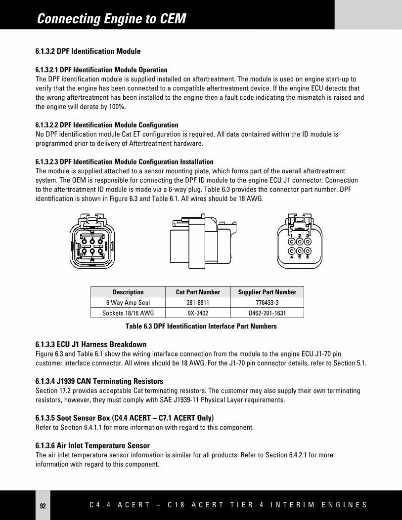
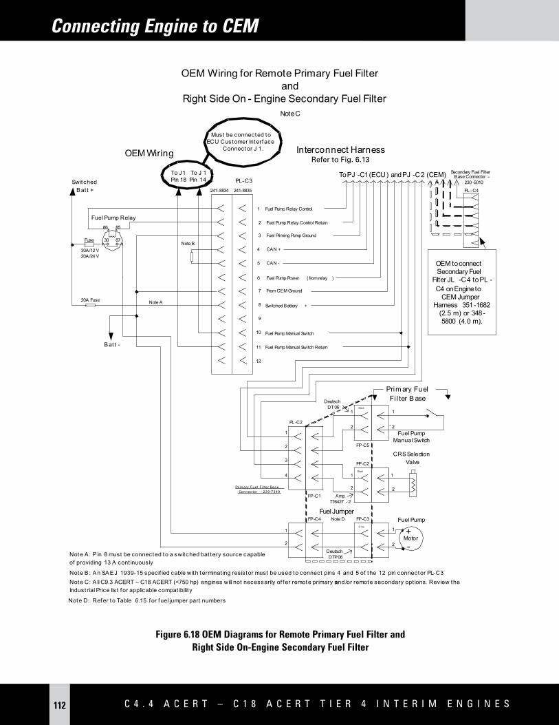
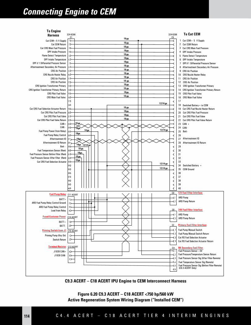
C 4 . 4 A C E R T – C 1 8 A C E R T T i E R 4 i N T E R i M E N g i N E s6
E L E C T R O N I C S a p p L I C a T I O N a N d I N S T a L L a T I O N G U I d E 7
Introduction and Purpose
1.0 Introduction and Purpose
1.1 PurposeThis document is intended to provide the necessary information for correct electrical and electronic installation of the following Cat® EPA Tier 4 Interim and/or Euro Stage IIIB Industrial engines into off-highway engine applications: C4.4 ACERT™, C6.6 ACERT, C7.1 ACERT, C9.3 ACERT, C13 ACERT, C15 ACERT, and C18 ACERT.
The primary purpose is to assist engineers and designers specializing in engine installations. The A&I Manual and Supplement Guide, Engine Application and Installation Guide, and TMI complement this booklet. Reference these documents as required.
Note: The information in this document is subject to change as engine feature requirements are revised and software continues to be developed. In addition, some of the features described in this document are not yet released.
The information in this document is the property of Caterpillar Inc. and/or its subsidiaries. Without written permission, any copying, transmission to others, and any use except that for which it is loaned is prohibited.
1.2 Electronic Applications ContactsPlease contact [email protected] if further details are desired.
1.3 safetyMost accidents that involve product operation, maintenance and repair are caused by failure to observe basic safety rules or precautions. An accident can often be avoided by recognizing potentially hazardous situations before an accident occurs. A person must be alert to potential hazards. This person should also have the necessary training, skills and tools in order to perform these functions properly.
The information in this publication was based upon current information at the time of publication. Check for the most current information before you start any job. Cat dealers will have the most current information.
Improper operation, maintenance or repair of this product may be dangerous. Improper operation, maintenance or repair of this product may result in injury or death.
Do not operate or perform any maintenance or repair on this product until you have read and understood the operation, maintenance and repair information.
Caterpillar cannot anticipate every possible circumstance that might involve a potential hazard. The warnings in this publication and on the product are not all inclusive. If a tool, a procedure, a work method or an operating technique that is not specifically recommended by Caterpillar is used, you must be sure that it is safe for you and for other people. You must also be sure that the product will not be damaged. You must also be sure that the product will not be made unsafe by the procedures that are used.
Introduction and Purpose
C 4 . 4 A C E R T – C 1 8 A C E R T T i E R 4 i N T E R i M E N g i N E s8
1.3.1 Warning – WeldingWelding can cause damage to the on-engine electronics. The following precautions should be taken before welding:• Turn the engine OFF. Place the ignition keyswitch in the OFF position.• Disconnect the negative battery cable from the battery. If the application is installed with a battery disconnect
switch then open the switch.• Clamp the ground cable of the welder to the conductive area that will be welded. Place the clamp as close as
possible to the weld. • Disconnect all electronic components of driven equipment including engine ECU, CEM and sensors from wiring
harness before welding. • Protect any wiring harnesses from welding debris and splatter. • Use standard welding procedures to weld the materials together.• Welding on the CEM frame/chassis is prohibited.
E L E C T R O N I C S a p p L I C a T I O N a N d I N S T a L L a T I O N G U I d E 9
Introduction and Purpose
DO NOT use electrical components in order to ground the welder. Do not use the ECU or sensors or any other electronic components in order to ground the welder.
1.3.2 Warning – Electrostatic Paint spraying
Warning: Painting the CEM is prohibited.
The high voltages used in electrostatic paint spraying can cause damage to on engine electronics. The damage can manifest itself through immediate failure of components, or by weakening electronic components causing them to fail at a later date.
The following precautions should be taken when using electrostatic paint spraying techniques on engines:• Connect all pins the ECU J1 connector directly to the spraying booth ground.• Connect the engine block to ground at two points. Ensure that good screwed connections onto bright metal
are used.
1.3.3 Warning – Jump startingJump-starting an engine can cause higher than normal voltages to appear across the battery terminals. Care must be taken that this does not exceed the recommended maximum voltage for the ECU.
1.3.4 Warning – High Voltage InjectorsWhen servicing and/or disconnecting the engine harness from the ECU, CEM or the engine head ensure, engine and keyswitch is turned OFF and allow the injector voltage to discharge.
1.3.5 Warning – Replacement Parts When replacement parts are required for this product, Caterpillar recommends using Cat replacement parts or parts with equivalent specifications including, but not limited to, physical dimensions, type, strength, and material.
Warning: Failure to heed these warnings can lead to premature failures, product damage, personal injury, or death.
Introduction and Purpose
C 4 . 4 A C E R T – C 1 8 A C E R T T i E R 4 i N T E R i M E N g i N E s10
1.4 Terminology
The terminology used throughout this document will be as follows:
AMOX Ammonia Oxidation Catalyst ARD Auxiliary Regeneration Device (also Cat Regeneration System)ATAAC Air-to-Air Aftercooled BPV Backpressure Valve CAC Charge Aircooled CAN Controller Area NetworkCB Circuit BreakerCEM Clean Emissions ModuleCDPF Catalyzed Diesel Particulate FilterCG Center of GravityCPS Compact Power SystemsCO Carbon MonoxideDelta P Differential Pressure DOC Diesel Oxidation Catalyst DPF Diesel Particulate Filter DSN Dealer Service NetworkECU Electronic Control Unit EGR Exhaust Gas Recirculation (also NRS)EU European UnionFEA Finite Elemental AnalysisFMEA Failure Modes & Effects AnalysisHC Hydro Carbonhp HorsepowerHSR High Speed Regeneration IdentificationIPU Industrial Power UnitIP Ingress ProtectionIVS Idle Validation SwitchIVA Intake Valve ActuationJ1/P1 Jack 1/Plug 1kW KilowattLPS Large Power SystemsLSR Low Speed Regeneration
E L E C T R O N I C S a p p L I C a T I O N a N d I N S T a L L a T I O N G U I d E 11
Introduction and Purpose
Terminology continued
MAF Mass Air FlowMEUI™ Mechanical Electronic Unit InjectorMPTS Multi Position Throttle SwitchNOx Nitrous Oxides – NO and NO2
NRS NOx Reduction System (also EGR)OEM Original Equipment ManufacturerPM Particulate Matter RSLL Rated Speed Lower LimitRSUL Rated Speed Upper LimitSCAC Separate Circuit AftercooledSCR Selective Catalytic Reduction S/N Serial Number TDC Top Dead CenterTPS Throttle Position Sensor
C 4 . 4 A C E R T – C 1 8 A C E R T T i E R 4 i N T E R i M E N g i N E s12
Engine & CEM Component Overview
2.0 Engine & CEM Component OverviewIndustrial Engine Electronic Component Table
A5:E2 ECU X XA4:E4 ECU X XEngine Connector (70/120 pin, J2/P2) 70 70 120 120CEM connector (31 pin, PJ-C1) XCEM connector (40 pin, PJ-C1) X XCustomer Connector (70-pin connector, J1/P1) X X X XMEUI Injector XCommon Rail Fuel Injector X X XSecondary Fuel Filter Differential Pressure Sensors XSecondary Fuel Filter Outlet Pressure Sensor XSecondary Fuel Filter Differential Pressure Switch X XFuel Rail Pressure Sensor (High Pressure Systems) X X XFuel Temperature Sensor X X X XFuel Pump Solenoid X XWater in Fuel Switch X XDual Speed/Timing Sensors X X X XCompression Brake Solenoids X(2)
Constant Lift Brake XBarometric Pressure Sensor X X X XCrank Case Pressure Sensor X XIntake Manifold Pressure Sensor X X X XIntake Manifold Air Temperature Sensor X XCoolant Temperature Sensor X X X XAir Inlet Temperature Sensor X X X XOil Pressure Sensor X X X XSmart Wastegate Regulator Valve X XNRS Valve Actuator X X X XNRS Pressure Sensors (2) X X X XNRS Temperature Sensor X X X XExhaust Backpressure Valve XIntake Throttle Valve X(4)
NRS Balance Valve Actuator X XCharge Air Cooler Outlet Temperature Sensor X(3) X(3) X XIVA End of Rail Valve X(1)
IVA Oil Pressure Sensor X(1)
Cat Regeneration System Fuel Supply Pump and Relay X(5)
Cat Regeneration System Fuel Supply/Fuel Priming Pump X X(6)
Fuel Flow Selection Valve X X(6)
Cat Regeneration System Supply/Fuel Priming Pump Relay X(5) X(5)(6)
(1) C18 ACERT >/= 700 hp ratings only (4) Only used on C7.1 ACERT high power ratings(2) Certain ratings only – refer to price list (5) Relay may be customer supplied or purchased with the engine(3) Optional Customer-installed Option for C4.4 ACERT – (6) C18 ACERT engines > 750 hp / 560 kW do not require
C7.1 ACERT these components
E L E C T R O N I C S a p p L I C a T I O N a N d I N S T a L L a T I O N G U I d E 13
Engine & CEM Component Overview
2.1 Engine Control unit (ECu)The ECU is generally located on the left rear side of the engine. There are two connectors on the ECU and one integrated into the engine wiring harness. 2.1.1 Engine Connector (J2/P2)Engine system and control information is transmitted between the J2/P2 connector on the engine ECU and the engine components through the engine harness. The CEM connector is a breakout connector, which is part of the engine harness. The CEM connector is part of the engine wiring harness coming from the engine harness providing the interface to the following engine components:• Engine and CEM Sensors• Fuel Injection System• CEM System
2.1.1.1 CEM Connector CEM Connector provides a means of communication between the engine ECU and CEM device via an interconnect jumper harness. This harness provides wiring for:• Soot Sensor Control Box J1939 Data Link (C4.4 ACERT – C7.1 ACERT only)• Soot Sensor Power and Ground (C4.4 ACERT – C7.1 ACERT only)• CEM Sensors• CEM System Controls• CEM Power and Ground
CEM connection reference:• C4.4 ACERT & C6.6 ACERT: No breakout harness wiring comes from J1/P1• C7.1 ACERT: Breakout Engine Harness from J2/P2, 31-pin• C9.3 ACERT – C18 ACERT < 750 hp/560 kW: Breakout Engine Harness from J2/P2, 40-pin
2.1.2 Customer Connector (J1/P1)Customer control and display information is transmitted between the 70-pin connector on the engine ECU and the customer-installed components through the customer harness. The customer harness provides the interface to the following components:• Battery• Data links• Customer components• CEM
Note: Refer to 2.1.1.1 C4.4 ACERT & C6.6 ACERT CEM system and control communication is connected to J1/P1.
C 4 . 4 A C E R T – C 1 8 A C E R T T i E R 4 i N T E R i M E N g i N E s14
Engine & CEM Component Overview
2.2 software Flash FileIf the ECU is correlated to a computer, then the personality module (also known as “flash file”) is the software for the computer. The term flash file is derived from the method in which the software is programmed into the ECU – a technology known as flash programming. The flash file contains the operating maps that define the performance and operating characteristics of the engine as well as the Industrial application feature support. Once flashed, the ECU contains the following information to identify the flash file and supported ratings:• Personality Module PN• Software Gp Release Date• Software Gp Description• Rating Number• Rated Power• Rated Peak Torque• Test Spec
The information above can be viewed in the Configuration screen within the Cat ET service tool.
2.3 Engine sensor detailsThis section is to give details of the engine sensors and actuators that either will be installed when the engine is delivered to the customer or must be installed by the customer in each installation.
Note: Reference the chart at the beginning of Section 2 for details regarding which sensors and actuators are included on each engine model.
2.3.1 Fuel system
2.3.1.1 MEUI Injector (C13 ACERT – C18 ACERT)The injector lobe on the camshaft mechanically actuates the Mechanical Electronic Unit Injector (MEUI) fuel injectors. The electronic control and mechanical actuation provide a level of control of the timing and fuel volume. The timing advance is achieved by precise control of the unit injector timing. Higher voltages (approximately 108V) and sharp pulses of relatively high current are used to control the injectors. There is no OEM connection to the injectors; however, the OEM should ensure that any systems that are sensitive to electromagnetic radiation are not in proximity to the harness that leads to the injectors.
2.3.1.2 Common Rail InjectorEach fuel injector contains a solenoid to control the quantity of fuel injected. Higher voltages (approximately 70V) and sharp pulses of relatively high current are used to control the injectors. There is no OEM connection to the injectors; however, the OEM should ensure that any systems that are sensitive to electromagnetic radiation are not in proximity to the harness that leads to the injectors.
2.3.1.3 Secondary Fuel Filter Differential Pressure SensorsFuel pressure is sampled in the secondary fuel filter base before and after the secondary fuel filter. These two sensors are used by the engine control in order to monitor the condition of the secondary fuel filter. This sensor input is used for engine monitoring.
E L E C T R O N I C S a p p L I C a T I O N a N d I N S T a L L a T I O N G U I d E 15
Engine & CEM Component Overview
2.3.1.4 Secondary Fuel Filter Outlet Pressure Sensor Fuel pressure is sampled in the secondary fuel filter base after the secondary fuel filter. This sensor is used by the engine control in order to monitor for a low-pressure condition at the outlet of secondary fuel filter. This sensor input is used for engine monitoring.
2.3.1.5 Secondary Fuel Filter Differential Pressure Switch (C4.4 ACERT – 7.1 ACERT)Fuel pressure is sampled in the secondary fuel filter base before and after the secondary fuel filter, using a differential pressure switch. This switch is used by the engine control in order to monitor the condition of the secondary fuel filter. This sensor input is used for engine monitoring. Option for C4.4 ACERT – C7.1 ACERT engines.
2.3.1.6 Fuel Rail Pressure Sensor (Common Rail System)The fuel rail pressure sensor is used to measure the fuel pressure in the high-pressure fuel rail. The fuel in the fuel rail feeds all injectors. Injection takes place when each injector is electrically operated. The fuel rail pressure measurement is used in conjunction with the high-pressure fuel pump to maintain the desired fuel pressure in the fuel rail. This sensor input is used for engine monitoring.
2.3.1.7 Fuel Temperature Sensor Fuel temperature is monitored at various points in the fuel system across the product line. The fuel temperature sampling location is specific to each fuel system type. The fuel temperature measurement is used to adjust fuel system component performance. This is required since fuel characteristics will vary across the range of allowable fuel temperatures. This sensor input is used for engine monitoring.
2.3.1.8 Fuel Pump SolenoidThe fuel pump solenoid, located on the suction control valve, is used to control the output from the high-pressure fuel pump. The suction control valve meters the fuel flow to the fuel pump based upon a signal from the ECU.
2.3.1.9 Water in Fuel Switch (Customer-installed)The water in fuel switch is a customer-installed mandatory requirement for C4.4 ACERT, C6.6 ACERT and C7.1 ACERT engines. The water in fuel switch is used to indicate that the fuel filter water trap is full. The switch is installed at the bottom of the water trap and is immersed in diesel fuel during normal operation. As water collects and reaches the maximum level, the water enables a conductive path between electrodes, and the engine ECU broadcasts an event code. It is the customer’s responsibility to connect this switch to the ECU J1/P1 connector. Refer to Customer-installed Sensors 7.3 for further details. This sensor input is used for engine monitoring.
2.3.2 dual speed Timing sensorsThe engine speed/timing sensors are used to determine both engine speed and fuel injection timing. Camshaft timing sensors may also be used for limp home operations in the event of a crank speed sensor/circuit failure. Speed/timing sensors work in conjunction with a timing ring installed to a rotating shaft (crankshaft, camshaft or high-pressure fuel pump shaft) to determine crankshaft or camshaft position. C4.4 ACERT – C7.1 ACERT engines have one camshaft speed/timing sensor located inside the high-pressure fuel pump and one crankshaft position sensor triggered by a target wheel on the crankshaft. The C9.3 ACERT has dual camshaft speed timing sensors. In this case, a target wheel on the camshaft triggers both sensors. C13 ACERT – C18 ACERT engines have one camshaft position sensor triggered by a target wheel on the camshaft and one crankshaft position sensor triggered by a target wheel on the crankshaft.
C 4 . 4 A C E R T – C 1 8 A C E R T T i E R 4 i N T E R i M E N g i N E s16
Engine & CEM Component Overview
2.3.3 Compression Brake solenoids Certain engines ratings are available with a compression brake. There is one compression brake actuator assembly per pair of adjacent cylinders and one control solenoid per brake assembly. The ECU directly drives the solenoid through the engine harness. One, two or three levels of engine braking may be available for each engine rating. Refer to the Engine Braking Section 10.1 for ratings available with compression brakes.
2.3.4 Barometric Pressure sensor The barometric pressure sensor measures the atmospheric pressure. The sensor is open to the atmosphere. The sensor data is used to assist in determining atmospheric pressure for proper engine performance at various altitudes.
2.3.5 Crankcase differential Pressure sensor The crankcase differential pressure sensor measures the level of crankcase pressure. This sensor data is used to determine proper range of pressure of the open crankcase system. Too high or too low pressure data will trigger fault and service will be required to address fault.
2.3.6 Intake Manifold Pressure sensorThe intake manifold air pressure sensor is used to determine pressure in the engine’s cylinder head or in the inlet manifold after charge airflow has been mixed with air from the Cat NOx reduction system. This is typically an absolute pressure sensor. Intake manifold pressure, as displayed by service tools and communicated over the data link, is the value obtained by subtracting the barometric pressure (as measured by the barometric pressure sensor) from the absolute value measured intake pressure sensor.
When the engine is running, the sensor measurement is used as an input parameter to calculate torque and air fuel ratio limits. This helps prevent black smoke during transient engine conditions, mainly during acceleration or upon sudden load application; i.e. if intake manifold pressure is too low for the requested fuel, the fuel is limited to prevent the over-fuel condition.
The sensor is also used to select certain timing maps and to control the turbocharger wastegate valve on engines using this hardware option.
2.3.7 Intake Manifold Air Temperature sensorThe intake manifold air temperature sensor is used to determine temperature in the engine’s cylinder head or in the inlet manifold after charge airflow has been mixed with air from the Cat NOx reduction system. This sensor input is used for engine monitoring.
2.3.8 Coolant Temperature sensorThe coolant temperature sensor is used to determine temperature of the coolant leaving the engine. This sensor input is used for engine monitoring and cold start strategies. Cold start strategies may include cold mode, glow plugs, air inlet heaters or either depending on engine and optional attachments. This sensor input is used for engine monitoring.
2.3.9 Air Inlet Temperature sensor (Customer-installed)This customer-installed sensor is required for all engines. Refer to Customer-Installed Sensors 6.4.2 for information.
E L E C T R O N I C S a p p L I C a T I O N a N d I N S T a L L a T I O N G U I d E 17
Engine & CEM Component Overview
2.3.10 Oil Pressure sensorThe oil pressure sensor measures engine oil pressure. The low oil pressure threshold is defined as a map against engine speed. This sensor input is used for engine monitoring and engine protection.
2.3.11 smart Wastegate RegulatorThe regulator valve controls the pressure in the intake manifold to a value that is determined by the ECU. The wastegate regulator provides the interface between the ECU and the mechanical system that regulates intake manifold pressure to the desired value that is determined by the engine software.
2.3.12 nRs Valve ActuatorThe Cat NOx reduction system valve actuator regulates mass airflow through the NOx reduction cooler into the intake manifold.
2.3.13 nRs Pressure sensors There are two Cat NOx reduction system pressure sensors, one positioned on the inlet to the NRS valve and one positioned on the outlet of the valve. This differential data is just one of the parameters needed to assist in calculating the amount of the mass airflow required to pass through the Cat NOx reduction system.
2.3.14 nRs Temperature sensorThis sensor is a required for temperature measurement to assist in the calculation of the Cat NOx reduction system mass airflow. The NRS valve differential pressure and the mass airflow temperature are used by the ECU to determine the appropriate mass airflow of the NRS system.
2.3.15 Thermal Management Valve (C4.4 ACERT – C6.6 ACERT Only)The thermal management valve is an exhaust backpressure valve used to elevate the engine exhaust temperature. Elevating exhaust system temperature helps enable catalyzed DPF regeneration.
2.3.16 Intake Throttle On some high power C7.1 ACERT engine ratings this component is required as an additional means to regulate mass flow through the Cat NOx reduction system cooler. It does this by restricting the flow of fresh air into the engine causing more NOx reduction flow into the intake manifold.
2.3.17 nRs Balance Valve Actuator (C9.3 ACERT – C18 ACERT)The balance valve actuator is used to provide the ECU with control of the two-position balance valve located in the turbo.
2.3.18 Charge Air Outlet Temperature sensor (Customer-installed on C4.4 ACERT – C7.1 ACERT)The charge air out temperature sensor is used to determine the air temperature just before air from the charge air cooler is mixed with Cat NOx reduction flow. One use of this measurement is to enable engine control of the cooling fan. This sensor is optional and customer-installed on C4.4 ACERT – C7.1 ACERT engines. This sensor is installed at the factory into the air inlet elbow/s on C9.3 ACERT – C18 ACERT engines.
C 4 . 4 A C E R T – C 1 8 A C E R T T i E R 4 i N T E R i M E N g i N E s18
Engine & CEM Component Overview
2.3.19 Intake Valve Actuation (IVA) Oil system Control Valve The IVA oil system valve controls the flow of oil through the valve actuation manifold.
2.3.20 Intake Valve Actuation (IVA) Pressure sensorThe IVA pressure sensor measures the oil pressure in the oil rail. The sensor is located at the valve cover base.
2.3.21 Cat Regeneration system Fuel supply Pump & RelayC7.1 ACERT engines use a dedicated Cat Regeneration System fuel supply pump. The purpose of this pump is to provide fuel supply to the Cat Regeneration System system during a regeneration event. ECU control of the Cat Regeneration System pump is required. When the engine determines that a regen is needed, it energizes the fuel pump relay to supply fuel flow to the Cat Regeneration System.
2.3.22 Cat Regeneration system Fuel supply/Priming Pump, Relay & Fuel Flow selection ValveC9.3 ACERT – C18 ACERT <750 hp/560 kW) engines use a single fuel pump to provide engine priming and Cat Regeneration System fuel supply. In fuel priming mode, the pump replaces hand operated fuel-priming pumps. In Cat Regeneration System fuel supply mode, the pump supplies fuel to the Cat Regeneration System system during a regeneration event. Since one pump is providing fuel flow for two different systems, a fuel flow selection valve is used to provide a fuel flow path to CEM and to the engine fuel circuit in priming mode. The fuel pump and fuel flow selection valve are integrated into the primary fuel filter head on the C9.3 ACERT – C18 ACERT < 750 hp/ 560 kW engines. ECU control of both the selection valve and pump is required. When operating in fuel priming mode, the ECU receives a momentary operator input then energizes both the fuel flow selection valve and the fuel pump relay. The fuel pump relay is energized only in Cat Regeneration System Mode when the engine ECU determines that regeneration of the DPF is needed or has been requested. The fuel flow selection valve directs fuel to the Cat Regeneration System when it is not energized.
Note: When operating this system in fuel priming mode, the engine’s keyswitch power must be turned on.
2.4 Clean Emissions Module (CEM)
CEM Components
C4.4 ACERT C6.6 ACERT
C7.1 ACERTC9.3 ACERT – C18
ACERT(<750 hp)
Aftertreatment ID X X XDPF Inlet Exhaust Gas Temperature Sensor X X XDPF Inlet Exhaust Gas Pressure Sensor X XFlame Detection Temperature Sensor X XFuel Pressure Sensors X XCombustion Air Control Valve X XCombustion Air Pressure Sensor X XFuel Pressure Control Valves X XHot Nozzle Heater and Relay X XSpark Plug X XIgnition Coil X XSoot Sensor X XCat Regeneration System Fuel Supply Pump and Relay
Review Engine Component Overview for Information
Fuel Flow Selection ValveCat Regeneration System Fuel Supply/Fuel Priming PumpCat Regeneration System Fuel Pump Relay
E L E C T R O N I C S a p p L I C a T I O N a N d I N S T a L L a T I O N G U I d E 19
Engine & CEM Component Overview
2.4.1 Aftertreatment IdentificationAftertreatment Identification is an electrical device installed on C4.4 ACERT – C18 ACERT <750 hp/560 kW CEMs that allows the engine to confirm that it has been attached to a compatible CEM.
2.4.2 dPF Inlet Temperature sensorThe DPF intake temperature sensor measures exhaust gas temperature at the DPF inlet. This temperature is used to help determine when conditions are right for the system to regenerate.
2.4.3 dPF Inlet Pressure sensorThe DPF intake pressure densor measures pressure at the Cat Regeneration System head. This allows for calculating mass airflow through the combustion air valve.
2.4.4 Flame detection Temperature sensorA thermocouple is used to detect ignition and continued combustion by rate of change of temperature. If no ignition is detected after a certain time period, the regeneration will be delayed for 10 minutes before re-attempting. The flame detect sensor should detect a “flameout” within two seconds, at which point fuelling will stop; 10 “flameouts” are allowed before a fault code is logged and activated with appropriate Cat Regeneration System Mode action taken.
2.4.5 Fuel Pressure sensors Pilot and main fuel pressure sensors are installed to the outlet of the pilot and main fuel valves. These sensors are used to control the fuel flow via a calibrated fuel flow vs. pressure map. The ECU also monitors the signals from the fuel pressure sensors after the Cat Regeneration System is shut down. A code is activated if the pressure decay time is too long. Extended pressure decay time tends to indicate that the Cat Regeneration System fuel nozzle is restricted.
2.4.6 Combustion Air Control ValveThe Cat Regeneration System combustion air control valve is a butterfly valve with position feedback. This valve modulates combustion air from the combustion air manifold piped from the turbo compressor outlet. This butterfly valve is controlled by the engine ECU to achieve an optimal air/fuel ratio within the Cat Regeneration System combustion chamber during DPF regeneration.
2.4.7 secondary Air Flow Pressure sensorThe secondary air flow pressure sensor is located in the combustion air stream before the combustion air control valve. This sensor provides for accurate calculation of mass airflow to the Cat Regeneration System system.
2.4.8 Fuel Pressure Control Valves The Cat Regeneration System system uses a dual stage (pilot and main) fuel system. These valves control fuel flow to the Cat Regeneration System injector nozzle located in the Cat Regeneration System head. Closed loop feedback of the DPF inlet temperature is used by the ECU as part of the pilot and main valve control strategy.
2.4.9 nozzle Heater and RelayThere is a nozzle in the Cat Regeneration System head; this nozzle injects fuel into the Cat Regeneration System combustion zone. The nozzle can become plugged with carbon or debris over time. Carbon forms within the nozzle due to residual fuel after each regeneration. To prevent this carbon building up over time and reduce the flow through the nozzles, a heating coil around the nozzles burns off this carbon to restore the fuel flow.
C 4 . 4 A C E R T – C 1 8 A C E R T T i E R 4 i N T E R i M E N g i N E s20
Engine & CEM Component Overview
2.4.10 spark PlugThe spark plug is used to initiate combustion within the Cat Regeneration System and operates for a given duty cycle whenever engine operation is above 500 rpm.
2.4.11 Ignition CoilThe ignition coil works in combination with the spark plug to light the Cat Regeneration System and operates continuously when engine operation is above 500 rpm.
2.4.12 soot sensor (C4.4 ACERT – C7.1 ACERT Only)The DPF soot sensor provides a direct measurement of soot loading in the DPF via a dedicated J1939 data link to the ECU. This reading is broadcast on the diagnostic and programming J1939 data link and is used to maximize regeneration event interval and Cat Regeneration System fuel efficiency.
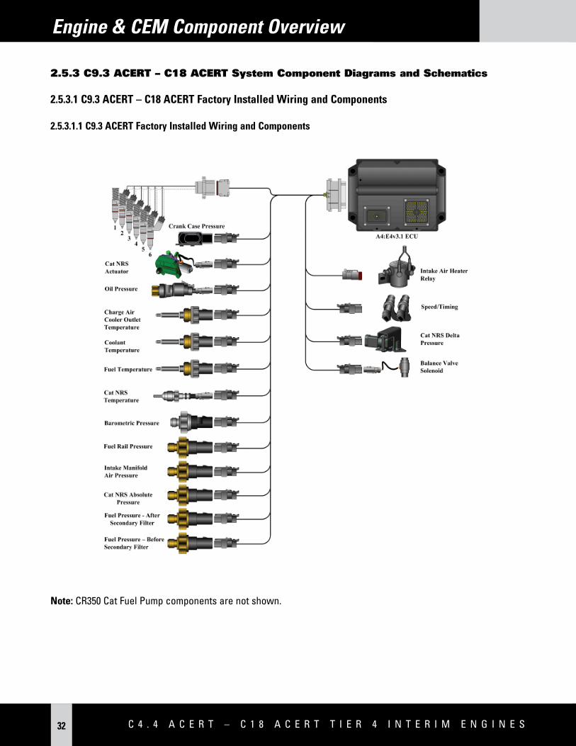
2.5 system Component diagrams and schematics
2.5.1 C4.4 ACERT & C6.6 ACERT system Component diagrams and schematics
2.5.1.1 C4.4 ACERT & C6.6 ACERT Engine Wiring and Components
ELECTRONIC CONTROL UNIT (ECU)
E L E C T R O N I C S a p p L I C a T I O N a N d I N S T a L L a T I O N G U I d E 21
Sensor locations on the left side of the C4.4 ACERT engine:
(1) Coolant temperature sensor (7) Suction control valve for the high pressure fuel pump(2) Intake manifold air temperature sensor (8) Fuel temperature sensor(3) Intake manifold pressure sensor (9) Barometric pressure sensor(4) Fuel rail pressure sensor (10) Primary speed/timing sensor(5) Water-in-fuel switch (11) Oil pressure sensor(6) Electronic Control Unit (ECU)
C 4 . 4 A C E R T – C 1 8 A C E R T T i E R 4 i N T E R i M E N g i N E s22
Engine & CEM Component Overview
Sensor locations on the right side and the top of the C4.4 ACERT engine:
E L E C T R O N I C S a p p L I C a T I O N a N d I N S T a L L a T I O N G U I d E 27
Engine & CEM Component Overview
2.5.2 C7.1 ACERT system Component diagrams and schematics
2.5.2.1 C7.1 ACERT Engine Wiring and Components
ELECTRONIC CONTROL UNIT(ECU)
C 4 . 4 A C E R T – C 1 8 A C E R T T i E R 4 i N T E R i M E N g i N E s28
Engine & CEM Component Overview
2.5.2.2 C7.1 ACERT Engine Electronic Components
Sensor locations on the left side of the C7.1 ACERT engine:
(1) Coolant temperature sensor (7) Connector for the aftertreatment module(2) Fuel temperature sensor (8) Electronic Control Unit (ECU)(3) Solenoid for the high pressure fuel pump (9) Atmospheric pressure sensor(4) Intake manifold air temperature sensor (10) Primary speed/timing sensor(5) Intake manifold pressure sensor (11) Oil pressure sensor(6) Fuel rail pressure sensor
E L E C T R O N I C S a p p L I C a T I O N a N d I N S T a L L a T I O N G U I d E 29
Engine & CEM Component Overview
Sensor locations on the right side and top of the C7.1 ACERT engine:
(12) Temperature sensor for the Cat NOx Reduction System (16) Engine intake throttle valve(13) Inlet pressure sensor for the Cat NOx Reduction System (17) Wastegate regulator(14) Outlet pressure sensor for the Cat NOx Reduction System (18) Secondary speed/timing sensor(15) Control valve for the Cat NOx Reduction System
C 4 . 4 A C E R T – C 1 8 A C E R T T i E R 4 i N T E R i M E N g i N E s30
Engine & CEM Component Overview
2.5.2.3 C7.1 ACERT Customer-installed CEM Wiring & Components
E L E C T R O N I C S a p p L I C a T I O N a N d I N S T a L L a T I O N G U I d E 31
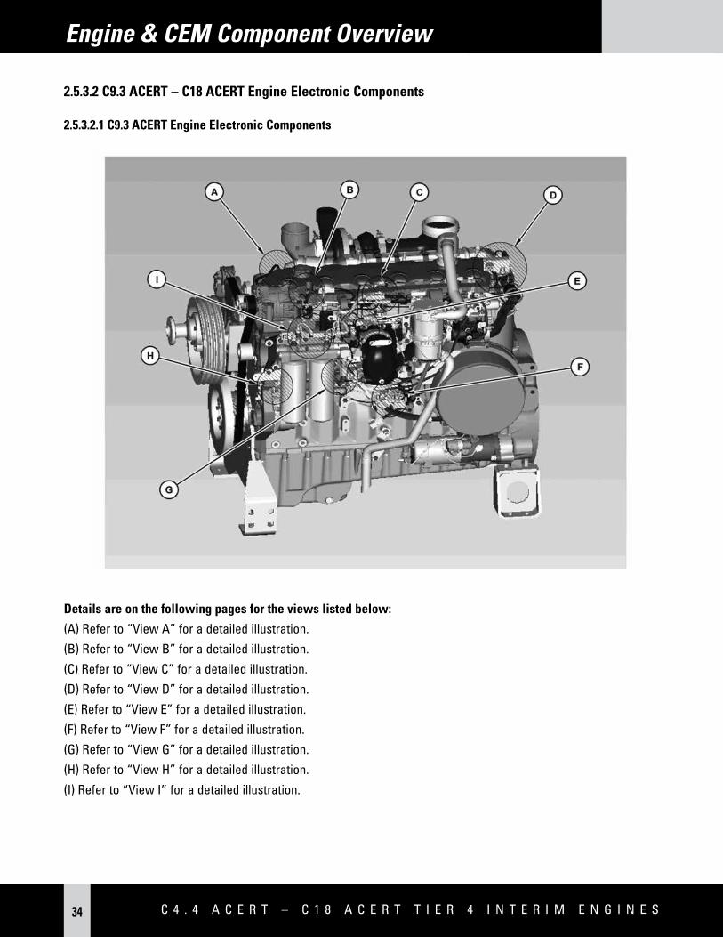
Details are on the following pages for the views listed below:
(A) Refer to “View A” for a detailed illustration.(B) Refer to “View B” for a detailed illustration.(C) Refer to “View C” for a detailed illustration.(D) Refer to “View D” for a detailed illustration.(E) Refer to “View E” for a detailed illustration.(F) Refer to “View F” for a detailed illustration.(G) Refer to “View G” for a detailed illustration.(H) Refer to “View H” for a detailed illustration.(I) Refer to “View I” for a detailed illustration.
E L E C T R O N I C S a p p L I C a T I O N a N d I N S T a L L a T I O N G U I d E 35
Engine & CEM Component Overview
View A View B
(1) Coolant temperature sensor (2) Intake manifold pressure sensor
E L E C T R O N I C S a p p L I C a T I O N a N d I N S T a L L a T I O N G U I d E 37
Engine & CEM Component Overview
View I
(13) Fuel pressure sensor at the inlet of the tertiary fuel filter(14) Fuel pressure sensor(15) Fuel pressure sensor at the outlet of the tertiary fuel filter
C 4 . 4 A C E R T – C 1 8 A C E R T T i E R 4 i N T E R i M E N g i N E s38
Locations of the engine sensors (typical left-side engine view):
(1) Differential pressure sensor for the crankcase (8) ECU J1 connector(2) Barometric pressure sensor (9) ECU J2 connector(3) Temperature sensor for the charged air cooler (10) CEM harness connector(4) Balance valve actuator (11) Terminator resistor(5) Connector for the injector harness (12) TDC probe(6) Intake manifold air pressure sensor (13) Secondary speed timing sensor “2” (camshaft)(7) Intake manifold air temperature sensor (14) Primary speed timing sensor “1” (crankshaft)
E L E C T R O N I C S a p p L I C a T I O N a N d I N S T a L L a T I O N G U I d E 39
Engine & CEM Component Overview
Locations of the engine sensors (typical top-engine view):
(1) Differential pressure sensor for the crankcase (15) NRS temperature sensor(2) Barometric pressure sensor (16) NRS absolute pressure sensor(3) Temperature sensor for the charged air cooler (17) NRS actuator(4) Balance valve actuator (18) NRS Delta-P pressure sensor(5) Connector for the injector harness
C 4 . 4 A C E R T – C 1 8 A C E R T T i E R 4 i N T E R i M E N g i N E s40
Engine & CEM Component Overview
Locations of the engine sensors (typical right-side engine view):
(19) Coolant temperature sensor (20) Fuel pressure sensor(21) Fuel temperature sensor
E L E C T R O N I C S a p p L I C a T I O N a N d I N S T a L L a T I O N G U I d E 41
(1) Combustion air valve (9) Cat Regeneration System fuel manifold filter(2) Combustion air valve controller (10) Coolant in/out(3) Cat Regeneration System ignition coil (11) Coolant in/out(4) Combustion air absolute pressure sensor (12) Pilot fuel control valve(5) Combustion air control group (13) Main fuel control valve(6) Absolute pressure sensor (14) Pilot fuel pressure sensor(7) Relay for the Cat Regeneration System nozzle heater (15) Main fuel pressure sensor(8) CEM connector to the ECU (16) Exhaust inlet
E L E C T R O N I C S a p p L I C a T I O N a N d I N S T a L L a T I O N G U I d E 43
CEM overview (typical example):(1) Muffler (8) CEM connector to ECU(2) Exhaust outlet (9) Combustion air valve(4) Diesel particulate filter (10) Exhaust inlet(5) DOC/inlet cap (11) Outlet cap(7) Absolute pressure sensor (12) Cat Regeneration System head
Engine & CEM Component Overview
C 4 . 4 A C E R T – C 1 8 A C E R T T i E R 4 i N T E R i M E N g i N E s44
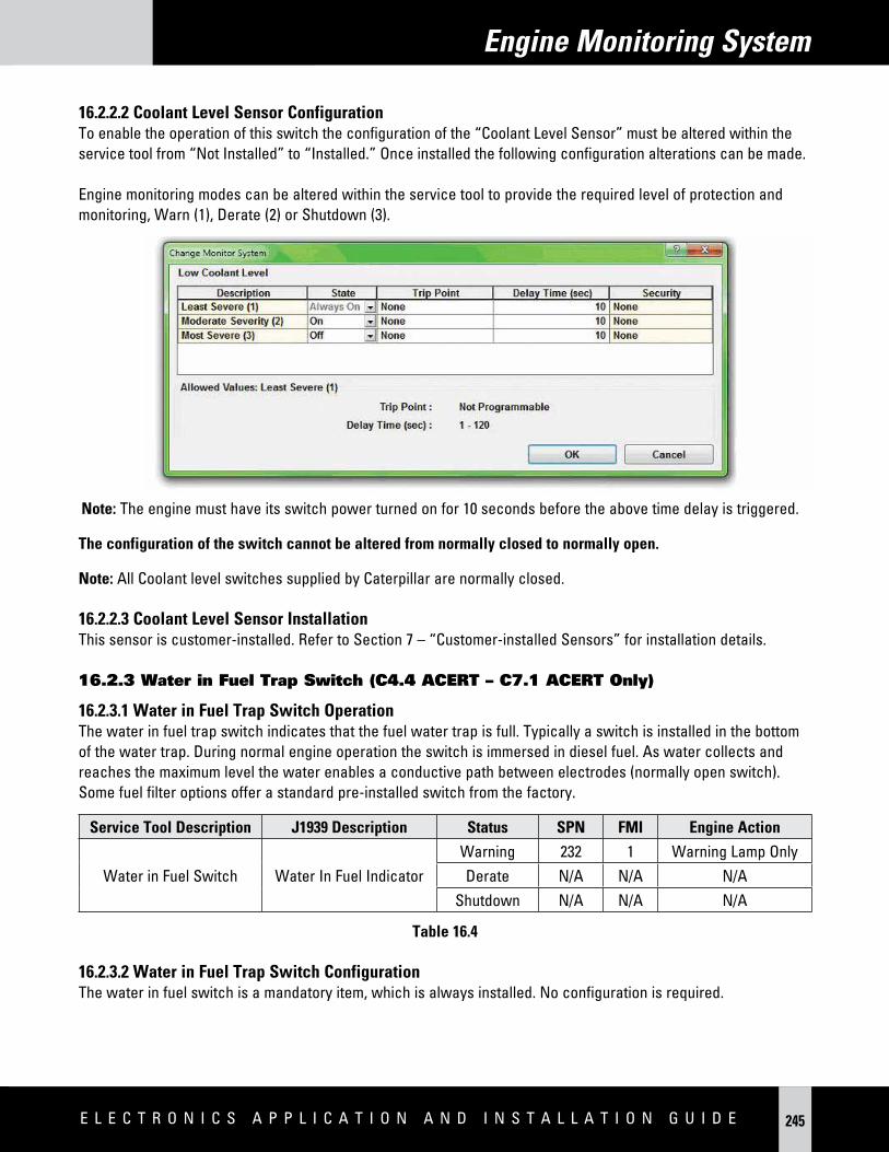
Certain installation requirements must be fulfilled in order for an installation to be acceptable to Caterpillar.
Mandatory ComponentsC4.4 ACERT
&C6.6 ACERT
C7.1 ACERT
C9.3 ACERT – C18 ACERT
<750 hp/560 kW
Section
Battery X X X Power and Grounding Considerations
Circuit Protection X X X Power and Grounding Considerations
Engine to CEM interconnection Harness X X X(3) Connecting Engine to CEM
Keyswitch X X X Starting and Stopping the Engine
Warning Lamp(1) X X X Engine & CEM Indicators & Operator Displays
Shutdown Lamp(1) X X X Engine & CEM Indicators & Operator Displays
Wait to Start Lamp(1) X X Engine & CEM Indicators & Operator Displays
Glow Plug Relay X X Cold Starting Aid
Speed Demand Input X X X Engine Speed Demand
Engine Service Tool Connector wiring X(2) Connectors and Wiring Requirements
LSR Enable X(4) X(4) X(4) Regeneration System & Operator Interface
HSR Enable X(4) X(4) Regeneration System & Operator Interface
DPF Lamp (1) X X Engine & CEM Indicators & Operator Displays
HEST Lamp(1) X X Engine & CEM Indicators & Operator Displays
Regen Inhibited Lamp(1) X X Engine & CEM Indicators & Operator Displays
Regeneration Inhibit Switch(1) X X Regeneration System & Operator Interface
Regeneration Forced Switch(1) X X Regeneration System & Operator Interface
Cat Regeneration System Fuel Pump X X Connecting Engine to CEM
Elect Fuel Lift Pump X X Connecting Engine to CEM
DPF Soot Sensor Control Box X X Connecting Engine to CEM
DPF Inlet Temperature Sensor X Connecting Engine to CEM
Water in Fuel Sensor X X Monitored Inputs for Customer-installed Sensors
Inlet Air Temperature X X X Connecting Engine to CEM
(1) Requirement may be fulfilled by a J1939 display capable of utilizing and displaying J1939 messages to replace lamps and switches.(2) Requirement is available by purchasing optional 70 to 70-pin (previously 70 to 40-pin) customer harness. If purchased, this harness
includes the 9-pin service tool wiring and connector.(3) Requirement is available by purchasing standard length interconnect harnesses from Caterpillar. Refer to the Industrial Price List or your
Caterpillar Application and Installation Engineer for details including available lengths.(4) In some cases, this input may not be necessary. Review the relevant section of this guide and if necessary, contact Caterpillar or your
Cat dealer application and installation engineer for details.
E L E C T R O N I C S a p p L I C a T I O N a N d I N S T a L L a T I O N G U I d E 45
Customer System Overview
3.2 Minimum Mandatory CEM Connection & Interconnection Customer Requirements
Component C4.4 ACERT, C6.6 ACERT
C7.1 ACERTC9.3 ACERT, C13 ACERT, C15
ACERT, C18 ACERT < 750 hp/560 kW
Cat Regeneration System X X
DOC X X X
DPF X X X
J1/P1 X X X
31-pin CEM connector X
40-pin CEM connector X(1)
(1) Customer may choose to connect to the primary and secondary fuel filters via this 40-pin interconnection harness.
3.3 Optional Customer Functionality
3.3.1 Optional Functionality Quick Reference ChartIndustrial engines offer a set of application features that can be specified by the customer to meet the application operating requirements. Application of these features requires a different set of customer-installed components based on the features selected. Each installation requires the minimum set of customer-installed components. See the identified section for further information.
C 4 . 4 A C E R T – C 1 8 A C E R T T i E R 4 i N T E R i M E N g i N E s46
Customer System Overview
Optional ComponentsC4.4 ACERT
&C6.6 ACERT
C7.1 ACERTC9.3 ACERT –
C18 ACERT < 750 hp/560 kW
Section
Low Oil Pressure Lamp X X Engine & CEM Indicators & Operator Displays
Maintenance Due Lamp X(2) X(2) X(2) Engine & CEM Indicators & Operator Displays
Remote Shutdown Switch X X X Starting and Stopping the Engine
Coolant Level Switch X X X Monitored Inputs for Customer-installed Sensors
Air Filter Restriction (Inlet Depression) Switch X X X Monitored Inputs for Customer-installed Sensors
1 or 2 PWM Throttle Position Sensors X X X Engine Speed Demand
1 or 2 Analog Throttle Position Sensors with Idle Validation Switch X X Engine Speed Demand
Throttle Arbitration Switch X X X Engine Speed Demand
Multi-Position Switch X X X Engine Speed Demand
Throttle Lock Selector Switch X X X Engine Speed Demand
Throttle Lock On/Off Switch X X X Engine Speed Demand
Throttle Lock Set/Lower Switch X X X Engine Speed Demand
Throttle Lock Raise/Resume Switch X X X Engine Speed Demand
Throttle Lock Disengage Switch X X X Engine Speed Demand
Mode Switches X X Engine Governor
Governor/Intermediate Engine Speed Switch X X X Engine Speed Demand
Ether Start X X X Cold Starting Aid
Engine Cooling Fan Control X X X Engine Cooling Fan control
Oil Level Switch X X Monitored Inputs for Customer-installed Sensors
2 Auxiliary Temperature Sensors X(4) X(4) X Monitored Inputs for Customer-installed Sensors
1 Auxiliary Pressure Sensor X X X Monitored Inputs for Customer-installed Sensors
Overspeed Verify Switch X X X Engine Speed Demand
Air Shutoff Relay X X X Starting and Stopping Engine
Charge Air Cooler Outlet Temperature Sensor X X X(3) Engine Cooling Fan control
Fan Reverse Switch X X X Engine Cooling Fan control
Reversing Fan Dout X X X Engine Cooling Fan control
Analog Pitch Sensor Input for Flexxaire Fan X X X Engine Cooling Fan control
(1) C9.3 ACERT uses Constant Lift Brake Switch. C13 ACERT – C18 ACERT engines use compression brakes.(2) Maintenance due lamp available only via a J1939 message.(3) Charge air cooler outlet temp sensor is factory installed on all C9.3 ACERT – C18 ACERT engines. (4) C4.4 ACERT – C7.1 ACERT engines provide only one auxiliary temperature sensor.
E L E C T R O N I C S a p p L I C a T I O N a N d I N S T a L L a T I O N G U I d E 47
Customer configuration parameters are ECU software settings that the customer can change in order to suit the needs of the specific application. These parameters are changed within the configuration screen in Cat ET. If a customer has more than one engine that should have the same configuration, the fleet configuration option is available to save the configuration settings to a file and download the settings to all subsequent engines that are to have the same configuration settings. Default values for these parameters are set in the factory when the new ECU is flash programmed for the first time. The customer configuration parameters may be reprogrammed if the ECU is flashed programmed for the first time. Refer to the Cat ET Service Tool Features Section for System Configuration Parameters for a complete list of supported programmable parameters. Further definition of each parameter can be found within the section of the document that defines a software feature that uses the parameter to support installation or operation of that specific software feature.
Customer configuration parameters in legacy product that are no longer supported:• C7 ACERT – C18 ACERT Maintenance Lamp (Section 15.4 LEBH4623)
Notes on Programming Parameters
1. Changing parameters protected by factory passwords may void Caterpillar warranty. Consult industrial application support center or dealer support network prior to making any changes.
2. In order for the programmed values to change, the keyswitch (switched power only) may need to be cycled off and on.
3. If there is an interlock error (personality module mismatch), then the programmed parameters will not change. It may appear that the parameters are changed, but they will not change until the “Personality Module Mismatch” code is cleared.
C 4 . 4 A C E R T – C 1 8 A C E R T T i E R 4 i N T E R i M E N g i N E s48
Customer System Overview
3.4 Typical Customer-Installed Component diagram
The engine can be configured and wired in many different ways depending upon the application features selected. The following examples act as a guide for the customer.
Basic ApplicationThis solution is suitable for applications where very little integration or additional engineering is required when compared to the solution used for a mechanical engine. This solution can be used in most mechanically governed engine replacement situations. The customer needs to consider only basic functions: power supply, operator indication, cold start aid, a method of controlling the engine and as with all Tier 4 applications, a mandatory interface to the engine aftertreatment system.
Construction ApplicationAn application where the engine, in response to an arrangement of switched inputs, will operate at one of a range of defined speeds. This is suitable for applications where the device has multiple operating speeds that are defined for the specific output reasons, for simplicity of operator use, or for operation dependent upon the environment; i.e., quiet modes this could include auxiliary engine on-road sweeper, multiple speed water pumps etc. There are sixteen possible set speeds based on four discrete ECU inputs. In addition to the keyswitch, a separate engine shutdown switch is used to stop the engine.
Industrial Open Power Unit ApplicationAn application where the engine, in response to a control input such as a depressed button, accelerates from idle speed up to the pre-defined operating engine speed. Once at the pre-defined operating speed, the engine speed may be raised or lowered by increment/decrement buttons. This functionality may benefit the user when they wish to use a “set speed operation,” but with the capability to adjust the set speed manually. Applications could include concrete pumps and hydraulic driven applications.
Example Agricultural Application (C7.1 ACERT Only)The application will allow single or twin throttles, engine twin set speed control, multi-mode operation, integrated display drive, etc. This set-up is suitable for applications where the customer requires a high degree of operator control over the application’s behavior. It is one of the most complex applications. Typically, this is used in mobile applications that may be driven to the place of work and require operator selectable speed operation while performing their chosen task. Applications include tractors, combines and backhoe loaders.
E L E C T R O N I C S a p p L I C a T I O N a N d I N S T a L L a T I O N G U I d E 49
17 AIR INLET TEMPERATURE SENSOR12AIR INLET TEMPERATURE SENSOR
57 BATTERY +
12 ETHER START AID SOLENOID
5 DIGITAL SENSOR RETURN
ETHER START AID SOLENOID
3 ANALOG SENSOR RETURN
8AWG
MODE SWITCH 1
MODE SWITCH 2
PWMTHROTTLESENSOR 1
66 PWM THROTTLE SENSOR INPUT
5Amp
Note 5
59 ACTUATOR DRIVER RETURN
35 WATER IN FUEL SWITCH3
21
WATER IN FUEL SWITCH
49 COOLANT LEVEL SWITCHA
BC
COOLANT LEVEL SWITCH
ELECTRONIC LIFT PUMP
1
2
BATT +
BATT -
1. CAN shield connection at ECM is optional2. Fuses must be as close to battery as possible. ECM main supply fuses should be Rated to meet the current requirements contained within the Electrical / Electronic A&I Guide. ECM supply must not be taken from starter motor terminals3. CDL connection may be used for secondary diagnostic connection4. Fit suppression diodes across relay coils and solenoids5. Glow Plug fuse rating differs between 4cyl and 6cyl engines6. Starter motor control circuits will vary7. ECM Power supply splices should be made using 14AWG cable for mechanical strength and current carrying capability.
NOTES
NOTE 7
NOTE 7
A5E2 ECUJ1 CONNECTOR
C 4 . 4 A C E R T – C 1 8 A C E R T T i E R 4 i N T E R i M E N g i N E s50
Customer System Overview
3.4.1.2 C7.1 Basic Schematic OEM Harness
A5E 2 ECM J 1 CONNECTOR
OFFON
START
IGNITION KEY
SWITCH SHUTDOWN LAMP
WARNING LAMP
48 BATTERY +
1 ..2. Fuses must be as close to battery as possible. Refer to
4.1.4 for ECM main supply fuse sizing. ECM supply must not be taken from starter motor terminals. .3 . CDL connection may be used for secondary
diagnostic connection .4 . Fit suppression diodes across relay coils and
solenoids.5 . Glow Plug fuse rating differs between 4 cyl and 6
cyl engines.6 . Starter motor control circuits will vary .7 . All Cables are to be 18 AWG or 0.82 mm 2 with GXL
insulation unless alternative sizes are stated within table 1 on page 2 of this schematic.
NOTES
UNCONTROLLED DOCUMENT FOR INDICATION ONLY
Caterpillar Confidential Green
Battery
OEM Wiring Schematic DRAFT
52 BATTERY +
53 BATTERY +
55 BATTERY +
61 BATTERY -
63 BATTERY -
65 BATTERY -
67 BATTERY -
69 BATTERY -
28 SHUTDOWN LAMP
29 WARNING / DERATE
20GLOW PLUG START AID
RELAY
70 IGNITION KEYSWTICH
CAN J 1939 BUS
120 OHM
50 CAN A J 1939 +
34 CAN A J 1939 -
42 CAN A J 1939 SHIELDNOTE 1
19 WAIT TO STARTCOLD START - WAIT TO START LAMP
8 CDL +
9 CDL -NOTE 3
62 MODE SW 1
4 SENSOR SUPPLY 8V
TO GLOW PLUGSGLOW PLUG
RELAY
64INLET AIR RESTRICTION
SWITCH / MODE SW 2
TO STARTER MOTOR MAG
SWITCH
120 OHM
Battery
12 or 24 V
Refer to notes 2 and 5
CAN Display
2 ANALOG SENSOR 5 V SUPPLY
17AIR INLET TEMPERATURE
SENSOR12
AIR INLET TEMPERATURE SENSOR
57 BATTERY +
12 ETHER START AID SOLENOID
5 DIGITAL SENSOR RETURN
ETHER START AID SOLENOID
3 ANALOG SENSOR RETURN
B
14 AWG
14 AWG
14 AWG
14 AWG
14 AWG
14 AWG
14 AWG
14 AWG
14 AWG
14 AWG
8 AWG
C
MODE SWITCH 1
MODE SWITCH 2
66PWM THROTTLE SENSOR
INPUT
5 Amp
Note 5
59 ACTUATOR DRIVER RETURN
35 WATER IN FUEL SWITCHA
BC
WATER IN FUEL SWITCH
49 COOLANT LEVEL SWITCHA
BC
COOLANT LEVEL SWITCH
ELECTRIC LIFT PUMP RELAY
PWMTHROTTLESENSOR 1
NOTE 4
Ascent Lift Pump 21
45
46
HIGH SPEED REGEN ENABLE
LSR Enable
SWITCH RETURN18
HIGH SPEED REGEN ENABLE SW
LSR Enable
BATT +
BATT -
1
2
30DPF LAMP
7
23 FORCE REGENERATION SW .
INHIBIT REGENERATION SW .Auto
Force
Inhibit
MANUAL REGENERATION
CONTROL
DPF LAMP
CAN shield connection at ECM is optional
31 HEST LAMPHEST LAMP
A5E2 ECU
E L E C T R O N I C S a p p L I C a T I O N a N d I N S T a L L a T I O N G U I d E 51
1 . CAN shield connection at ECM is recommended. 2 . Fuses must be as close to battery as possible. ECM main supply fuse should be 30A. ECM supply must not be sourced from starter motor terminals.3 . CDL connection may be used for secondary diagnostic Connection.4 . Install suppression diodes across relay coils and solenoids.5 . Starter motor control circuits will vary.6 . All Cables are to be 18 AWG or 0.82 mm2 with GXLinsulation unless alternative sizes are stated.7 . The fuel priming pump switch may alternatively be wired to the 40 – pin CEM connector.
NOTES
HSR Enable47 HSR Enable Switch
14Electronic Fuel Pump Manual Prime Sw
Electronic Fuel Pump Manual Prime Sw (refer to Section 6.3.2 for specific details)
A4E4 v3.1 ECUJ1 CONNECTOR
C 4 . 4 A C E R T – C 1 8 A C E R T T i E R 4 i N T E R i M E N g i N E s52
Customer System Overview
3.4.2 Construction schematic OEM Harness
3.4.2.1 C7.1 ACERT Construction Schematic OEM Harness
17 AIR INLET TEMPERATURE SENSOR12AIR INLET TEMPERATURE SENSOR
57 BATTERY +
12 ETHER START AID SOLENOID
5 DIGITAL SENSOR RETURN
ETHER START AID SOLENOID
3 ANALOG SENSOR RETURN
8AWG
7 REGENERATION INHIBIT
23 FORCE REGENERATIONMANUALREGENERATIONCONTROL
AUTO
INHIBIT
FORCE
44 PTO SPEED SELECT 2 / USER DEFINED SHUTDOWN SWITCH
31 HEST LAMPHEST LAMP
13 DPF REGENERATION DISABLED LAMP
DPF REGEN DISABLED
USER DEF SHUTDOWN
PWMTHROTTLESENSOR 1
66 PWM THROTTLE SENSOR INPUT
5Amp
Note 5
59 ACTUATOR DRIVER RETURN
35 WATER IN FUEL SWITCH3
21
WATER IN FUEL SWITCH
49 COOLANT LEVEL SWITCHA
BC
COOLANT LEVEL SWITCH
46 LSR ENABLELSR ENABLE
ELECTRONIC LIFT PUMP
1
2
BATT +
BATT -
1. CAN shield connection at ECM is optional2. Fuses must be as close to battery as possible. ECM main supply fuses should be Rated to meet the current requirements contained within the Electrical / Electronic A&I Guide. ECM supply must not be taken from starter motor terminals3. CDL connection may be used for secondary diagnostic connection4. Fit suppression diodes across relay coils and solenoids5. Glow Plug fuse rating differs between 4cyl and 6cyl engines6. Starter motor control circuits will vary7. ECM Power supply splices should be made using 14AWG cable for mechanical strength and current carrying capability.
NOTES
NOTE 7
NOTE 7
45 HSR ENABLEHSR ENABLE
A5E2 ECUJ1 CONNECTOR
E L E C T R O N I C S a p p L I C a T I O N a N d I N S T a L L a T I O N G U I d E 53
Customer System Overview
3.4.2.2 C9.3 ACERT – C18 ACERT Construction Schematic OEM Harness
A4E4 V3.1 ECM J 1 CONNECTOR
OFF
ON
START
IGNITION KEY SWITCH
S HUTDOWN LAMP
WARNING LAMP
48 BATTERY +
1. CAN shield connection at ECM is recommendedd.2. Fuses must be as close to battery as possible. Refer to 4.1.4 for ECM main supply fuse sizing. ECM supply must not be taken from starter motor terminals.3. CDL connection may be used for secondary diagnostic connection.4. Install suppression diodes across relay and solenoid coils.5. Starter motor control circuits will vary.6. All cables are to be 18 AWG or 0.82 mm2 with GXL insulation unless alternative sizes are stated.7. The fuel priming pump switch may alternatively be wired to the 40 – pin CEM connector.
Electronic Fuel Pump Manual Prime Sw (refer to Section 6.3.2 for specific details.)
A4E4 v3.1 ECUJ1 CONNECTOR
C 4 . 4 A C E R T – C 1 8 A C E R T T i E R 4 i N T E R i M E N g i N E s54
Customer System Overview
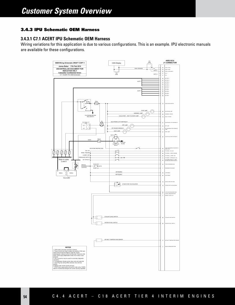
3.4.3 IPu schematic OEM Harness 3.4.3.1 C7.1 ACERT IPU Schematic OEM Harness Wiring variations for this application is due to various configurations. This is an example. IPU electronic manuals are available for these configurations.
17 AIR INLET TEMPERATURE SENSOR12AIR INLET TEMPERATURE SENSOR
57 BATTERY +
12 ETHER START AID SOLENOID
5 DIGITAL SENSOR RETURN
ETHER START AID SOLENOID
3 ANALOG SENSOR RETURN
8AWG
SET SPEED 2 44 PTO SPEED SELECT 2 / USER DEFINED SHUTDOWN SWITCH
5Amp
Note 5
59 ACTUATOR DRIVER RETURN
35 WATER IN FUEL SWITCH3
21
WATER IN FUEL SWITCH
49 COOLANT LEVEL SWITCHA
BC
COOLANT LEVEL SWITCH
ELECTRONIC LIFT PUMP
1
2
BATT +
BATT -
1. CAN shield connection at ECM is optional2. Fuses must be as close to battery as possible. ECM main supply fuses should be Rated to meet the current requirements contained within the Electrical / Electronic A&I Guide. ECM supply must not be taken from starter motor terminals3. CDL connection may be used for secondary diagnostic connection4. Fit suppression diodes across relay coils and solenoids5. Glow Plug fuse rating differs between 4cyl and 6cyl engines6. Starter motor control circuits will vary7. ECM Power supply splices should be made using 14AWG cable for mechanical strength and current carrying capability.
NOTES
NOTE 7
NOTE 7
30 DPF LAMPDPF LAMP
31 HEST LAMPHEST LAMP
13 DPF REGENERATION DISABLED LAMP
DPF REGEN DISABLED
7 REGENERATION INHIBIT
23 FORCE REGENERATIONMANUALREGENERATIONCONTROL
AUTO
INHIBIT
FORCE
46 LSR ENABLELSR ENABLE
45 HSR ENABLEHSR ENABLE
A5E2 ECUJ1 CONNECTOR
E L E C T R O N I C S a p p L I C a T I O N a N d I N S T a L L a T I O N G U I d E 55
Customer System Overview
3.4.3.2 C9.3 ACERT – C18 ACERT IPU Schematic OEM Harness (See Section 6.3.2 for details)
A4E4 V3.1 ECM J 1 CONNECTOR
OFF
ON
START
IGNITION KEY
SWITCHS HUTDOWN
LAMP
WARNING LAMP
48 BATTERY +
RAISE / RESUME
Battery
52 BATTERY +
53 BATTERY +
55 BATTERY +
61 BATTERY -
63 BATTERY -
65 BATTERY -
BATTERY -
28 SHUTDOWN LAMP
29 WARNING / DERATE
70 IGNITION KEYSWTICH
LOWER / SET
ON / OFF
41PTO MODE - DISENGAGE (NC)
DISENGAGE SWITCH
CAN J1939 BUS
120 OHM
50 CAN A J1939 +
34 CAN A J1939 -
42 CAN A J1939 SHIELDNOTE 1
DPF LAMPDPF LAMP
HEST LAMPHEST LAMP
8 CDL +
9 CDL -NOTE 3
60 PTO MODE – LOWER / SET
58PTO MODE - RAISE/
RESUME
56 PTO MODE - ON / OFF
TO STARTER MOTOR MAG
SWITCH
120 OHM
Battery
Refer to note 2
CAN Display
17AIR INLET TEMPERATURE
SENSOR12
AIR INLET TEMPERATURE SENSOR
12 ETHER START AID SOLENOID
ETHER START AID SOLENOID
3 ANALOG SENSOR RETURN
BATT +
8AWG
8AWG
14AWG
14AWG
14AWG
14AWG
14AWG
14AWG
14AWG
14AWG
BATT -to FRAME
SET SPEED 2 35 PTO SPEED SELECT 1/ 2
5Amp
49 COOLANT LEVEL SWITCHA
BC
COOLANT LEVEL SWITCH
69
30
31
12 or 24V
Negative Battery
MANUALREGENERATIONCONTROL
AUTO REGEN
FORCE
INHIBIT
LSR Enable
14
46
23
7
FUEL PRIMING PUMP
LSR Enable Switch
FORCE REGENERATION SWITCH
INHIBIT REGENERATION SWITCH
FUEL PRIMING PUMP SWITCHNOTE 7
13 REGEN DISABLED LAMPREGEN DISABLED LAMP
18 SWITCH INPUT RETURN
HSR Enable 47 HSR Enable Switch
64AIR INLET RESTRICTION SW.
AIR INLET RESTRICTION SW.
4 DIGITAL SENSOR 8V SUPPLY
Notes1. Can shield connection at ECM is recommended2. Fuses must be as close to battery as possible. Refer to 4.1.4 for ECM main supply fuse sizing. ECM supply must not be taken from starter motor terminals.3. CDL connection may be used for secondary diagnostic connection.4. Install suppressions diodes across relay coils and solenoids.5. Starter motor control circuits will vary.6. All cables are to be 18 AWG or .82 mm2 with GXL insulation unless alternative sizes are specified.7. The fuel priming pump switch may alternatively be wired to the 40 pin CEM connector.
14 Electronic Fuel Pump Manual Priming SwElectronic Fuel Pump Manual Prime Sw (refer to Section 6.3.2 for specific details)
A4E4 V3.1 ECUJ1 CONNECTOR
C 4 . 4 A C E R T – C 1 8 A C E R T T i E R 4 i N T E R i M E N g i N E s56
17 AIR INLET TEMPERATURE SENSOR12AIR INLET TEMPERATURE SENSOR
57 BATTERY +
12 ETHER START AID SOLENOID
5 DIGITAL SENSOR RETURN
ETHER START AID SOLENOID
3 ANALOG SENSOR RETURN
8AWG
SET SPEED 2 44 PTO SPEED SELECT 2 / USER DEFINED SHUTDOWN SWITCH
MODE SWITCH 1
5Amp
Note 5
59 ACTUATOR DRIVER RETURN
35 WATER IN FUEL SWITCH3
21
WATER IN FUEL SWITCH
49 COOLANT LEVEL SWITCHA
BC
COOLANT LEVEL SWITCH
ELECTRONIC LIFT PUMP
1
2
BATT +
BATT -
1. CAN shield connection at ECM is optional2. Fuses must be as close to battery as possible. ECM main supply fuses should be Rated to meet the current requirements contained within the Electrical / Electronic A&I Guide. ECM supply must not be taken from starter motor terminals3. CDL connection may be used for secondary diagnostic connection4. Fit suppression diodes across relay coils and solenoids5. Glow Plug fuse rating differs between 4cyl and 6cyl engines6. Starter motor control circuits will vary7. ECM Power supply splices should be made using 14AWG cable for mechanical strength and current carrying capability.
NOTES
C4.4 ACERT/C6.6 ACERT Agricultural OEM Schematic
A5E2 ECUJ1 CONNECTOR
E L E C T R O N I C S a p p L I C a T I O N a N d I N S T a L L a T I O N G U I d E 57
2 21 ELECTRIC LIFT PUMP RELAYELECTRIC LIFT PUMP RELAY
45
46
HIGH SPEED REGEN ENABLE
LSR Enable
HIGH SPEED REGEN ENABLE SW
LSR Enable
SHUTDOWN LAMP
23
7 INHIBIT REGENERATION SW.
FORCE REGENERATION SW.
AUTO
FORCE
INHIBITMANUAL
REGENERATION CONTROL
Notes1. Can Shield connection at ECM is recommended.2. Fuses must be as close to battery as possible. Refer to 4.1.4 for ECM main supply fuse sizing. ECM supply must not be taken from starter motor terminals.3. CDL connection may be used for secondary diagnostic connection.4. Install suppression diodes across relay coils and solenoids.5. Glow plug fuse rating differs between 4 cyl and 6 cyl engines.6. Starter motor control circuits will vary.7. All cables are to be 18 AWG or 0.82 mm2 GXL insulation unless alternative sizes are stated.
30 DPF Lamp
31 HEST Lamp
DPF Lamp
HEST Lamp
ENGINE ECUJ1 CONNECTOR
C 4 . 4 A C E R T – C 1 8 A C E R T T i E R 4 i N T E R i M E N g i N E s58
Customer System Overview
3.5 Customer Id & Passwords
3.5.1 Equipment Identification
3.5.1.1 Equipment Identification OperationEquipment identification is a configuration parameter that the customer can program in the ECU to uniquely identify an engine installation. Typical uses for the equipment identification parameter include manufacturer model number, machine number, installation location, etc. Configuration of this parameter is optional as the parameter is for customer reference only.
3.5.1.2 Equipment Identification ConfigurationOne parameter must be updated with Cat ET to set the equipment ID. The equipment ID defaults to “Not Programmed” and can be set to a customer-defined identification for the engine. A maximum of 17 characters may be entered in the field. Characters can be any alphanumeric character.
3.5.2.1 Customer Passwords OperationCustomer passwords are sometimes referred to as “OEM Passwords.” Customer passwords may be programmed in order to limit access to certain parameters. There are two customer passwords available. Both customer passwords do not need to be programmed in order to provide protection. If both customer passwords are programmed, then both are required to access and change the password-protected parameters. The only parameter protected with customer password is “Ether Solenoid Configuration.”
Customer Password Operation ChangesTier 4 changes from Tier 3 customer password operation are outlined below:• When customer passwords are entered, they are temporarily saved for the duration of the current ECU
connection. This permits users to continue service without repeatedly entering customer passwords and without having the current passwords memorized.
• If the customer passwords are unknown, users may click the “Factory Passwords” button in the Enter Customer Passwords dialog. This generates factory passwords and permits users to continue service without knowing customer passwords.
• If the ECU must be disconnected and then reconnected during servicing, the customer password reset/restore feature may be used.
E L E C T R O N I C S a p p L I C a T I O N a N d I N S T a L L a T I O N G U I d E 59
Customer System Overview
3.5.2.2 Customer Passwords ConfigurationOne or two parameters must be configured in Cat ET prior to using customer passwords:1. Customer Password #12. Customer Password #2Both passwords default to an empty field. The display shows “********” whether or not the password is set. A maximum of eight alphanumeric characters may be entered for each of the two available customer passwords. These passwords are case sensitive.
Key cycle is required after the passwords have been configured to activate the protection. This is true for most changes to programmable parameters detailed in this document for feature activation.
3.5.3.1 Parameter Lockout OperationParameter lockout changes the protection level of certain parameters from normal Cat ET access to factory password required. If customer passwords are programmed, these will also be required to lock an unlocked parameter in the parameter lockout Cat ET screen.
The following configuration parameters can be selected to be locked out: • High Idle Speed• Top Engine Limit • Intermediate Engine Speed • Low Idle Speed • Programmable Monitoring System
3.5.3.2 Parameter Lockout ConfigurationAccess the parameter lockout screen in the service menu of Cat ET. If customer passwords are programmed, they are required to access this screen. One or more of the listed configuration parameters can be locked or unlocked in one session. All parameters default to “unlocked.”
If a locked out parameter must be changed, there are two options:1. Remove the lockout – In the parameter lockout screen, a factory password allows the protection level to be
changed back to normal Cat ET access.2. Retain the lockout – In the configuration screen, a factory password allows changing the value one time.
C 4 . 4 A C E R T – C 1 8 A C E R T T i E R 4 i N T E R i M E N g i N E s60
Power and Grounding Considerations
4.0 Power and Grounding Considerations
4.1 Power Requirements
4.1.1 Engine system VoltageThe electronic control system is voltage specific. Engines configured in the Price List or Engines Sales Manual to be 12 VDC must be installed with 12 VDC supply. Engines configured in the Price List or Engines Sales Manual to be 24 VDC must be installed with 24 VDC supply. The correct system voltage must be applied (12V or 24V), the following engine system components are system voltage sensitive: • C4.4 ACERT – C7.1 ACERT Fuel Suction Control Valve• Smart Wastegate Regulator Valve • Intake Throttle Valve • Exhaust Backpressure Valve (C4.4 ACERT – 6.6 ACERT only)• NRS Valve Actuator• Cat Regeneration System Fuel Supply/Fuel Priming Pump (C7.1 ACERT – C18 ACERT < 750 hp/560 kW only)• Hot Nozzle Heater and Relay (C7.1 ACERT – C18 ACERT < 750 hp/560 kW only)• NRS Balance Valve Actuator
NOTE: All C9.3 ACERT – C18 ACERT engines are shipped with “System Operating Voltage” configured to 24 volt. All 12 volt applications must have this parameter configured to “12 volts” prior to installation. Refer to Section 18.2.1 “System Configuration Parameters” for parameter configuration details.
The switched positive battery and the unswitched positive battery connections to the ECU are made at the P1/J1 customer harness connector. The minimum battery voltage for the ECU to actuate the fuel injectors, regardless of system voltage (12 VDC or 24 VDC) is 9 VDC. The batteries, charging system, starter, and associated wiring must be sized and designed correctly to allow the starter to crank the engine to an appropriate minimum engine speed to start the engine. The engine installation should meet the minimum cranking speeds at the COLDEST ANTICIPATED TEMPERATURES. Refer to TMI System Data (C9.3 ACERT – C18 ACERT) or the Engine Sales Manual (C4.4 ACERT – C7.1 ACERT) for minimum cranking speed requirements.
4.1.2 Engine ECu Battery (+) ConnectionThe A5E2 (C4.4 ACERT – C7.1 ACERT) ECU requires five unswitched battery (+) inputs. The A4E4 (C9.3 ACERT – C18 ACERT) ECU requires four unswitched battery (+) inputs. These unswitched battery (+) inputs may be powered through a battery isolation switch. Battery isolation switches should be carefully selected. These switches can add significant resistance within the ECU power circuit. The A4E4 and A5E2 both require one switched power input. An ignition keyswitch typically powers this switched power input. When battery (+) is not applied to the switched input, the ECU is in sleep mode. When the ECU is in sleep mode it draws a very small residual current through the unswitched battery inputs. When the switched power is connected to battery (+), the ECU will become active, allowing the engine to start and run. The switched power for both ECUs is connected on pin P1/J1-70 and carries approximately 2 mA on a 12 VDC system and 4 mA on a 24 VDC system. The keyswitch should be used as the primary switch to power down the engine. The battery isolation switches should not be used to power down the engine.
E L E C T R O N I C S a p p L I C a T I O N a N d I N S T a L L a T I O N G U I d E 61
Power and Grounding Considerations
Note: There are certain Tier 2 and Tier 3 engine installations that were allowed to power off “switched” and “unswitched” power simultaneously. Tier 4 engines MUST use the keyswitch input only to power off the engine.
4.1.3 Correct Power supply WiringThe unswitched battery (+) input connections should run directly from the P1/J1 connector to the positive side of the battery. These inputs carry nearly all power to the ECU. Switched power must be turned off before connecting or disconnecting the ECU J1 connector. This helps prevent damage to the P1/J1 pins. Power to all designated unswitched battery (+) inputs must be provided to prolong the service life of the ECU.
C 4 . 4 A C E R T – C 1 8 A C E R T T i E R 4 i N T E R i M E N g i N E s62
Power and Grounding Considerations
4.1.4 Voltage and Current RequirementsThe ECU power supply requirements must be carefully considered when designing the supply circuit. There are specific limitations that must be considered in the design to ensure a reliable, consistent power supply to the engine electronic components.
Voltage Supply SystemC7.1 ACERT C6.6 ACERT & C4.4 ACERT
12V 24V 12V 24V
Max peak current (500uS) 68A 67A 55A 54A
Max peak current (150mS) 46A 45A 40A 39A
Peak current cranking 11A 9A 11A 9A
Max RMS current(1) 31A 26A 26A 22A
Suggested fuse rating(2) 40 A 30A 30A 30A
Sleep current <5 mA <4 mA <5 mA <4 mA
Key on current engine off <1A <1A <1A <1 A
Min running voltage 9V 18V 9V 18V
Max running voltage(3) 16V 32V 16V 32V
Minimum battery voltage during cranking 7.3V 7.3V 7.3V 7.3V
Maximum total ECU power circuit wire resistance 50 m Ohm 100 m Ohm 50 m Ohm 100 m Ohm
Target circuit resistance 40 m Ohm 80 m Ohm 40 m Ohm 80 m Ohm
Table 4.1 – CPS Engine Voltage Supply Requirements
(1) All Current measurements have been taken from Tier 4 Interim C4.4 ACERT – C7.1 ACERT Electronic System. Max RMS currents are based upon an engine speed of 2500 rpm with a DPF regeneration in progress for the C7.1 ACERT and running at rated speed for the C6.6 ACERT and C4.4 ACERT. RMS currents will vary with engine speed (assuming constant supply voltages). The current levels shown in the table were measurements made with no lamps or application side components installed. The system design, therefore, needs to account for any such added components.
(2) Suggested fuse rating are based on automotive blade type fuses and are for guidance only.(3) The ECU can survive higher voltages. ECU will survive for at least 5 minutes on a supply voltage of 60V.
Based on engine operating at rated speed and load with 65% input/output load.
Voltage Supply SystemA4E4 v3.1 C9.3 ACERT
A4E4 v3.1 C13 ACERT/C15 ACERT/C18 ACERT
12V 24V 12V 24V
Max peak current (.08 ms) 29.8 A – 29.8 A –Max peak current (.07 ms) – 42 A - 42 ANormal operating current – peak 47 A 39 A 46 A 38 APeak current crankingNormal RMS current 24 A 20 A 23 A 19 ASuggested fuse rating** 40 A 40 A 40 A 40 ASleep current (keyswitch off) 17 mA 14 mA 17 mA 14 mAKey On current Engine Off 895 mA 525 mA 895 mA 525 mAMin Running Voltage 9V 18V 9V 18VMax Running Voltage 16V 32V 16V 32VMaximum total ECU power circuit wire resistance 50 m Ohm 100 m Ohm 50 m Ohm 100 m OhmTarget circuit resistance 40 m Ohm 80 m Ohm 40 m Ohm 80 m Ohm
Table 4.2 – C9.3 ACERT – C18 ACERT LPS Engine Voltage Supply System Requirements
E L E C T R O N I C S a p p L I C a T I O N a N d I N S T a L L a T I O N G U I d E 63
Power and Grounding Considerations
4.1.5 Circuit ProtectionPowering the ECU through dedicated circuits with circuit protection reduces the possibility of degradation of electronic control system performance. This also minimizes the chance of an engine shutdown due to a short in the electrical system. Additional loads should not be connected between the ECU and the circuit protection for the ECU. Circuit protection wiring is illustrated in earlier in this section (4.1.3.) Caterpillar prefers the circuit protection to be located in the operator cab (if applicable). If not in the cab, for ease of service, the circuit protection should be located in an easily accessible and documented location.
Note: Caterpillar requires the use of circuit breakers or fuses for circuit protection. Circuit protection should be located with all other circuit protection in a centrally located, dedicated panel. If circuit breakers that automatically reset are used, consideration of the environment of the location of the breaker is critical as it can affect the breaker trip point. The trip point of some circuit breakers can be significantly reduced below the rated trip point if the circuit breaker is exposed to high temperatures. This can cause intermittent shutdowns that result in the needless replacement of electronic components.
4.1.6 ECu Power supply Circuit Resistance Often during engine cranking the battery voltage will drop to values much lower than the normal system operating voltage. Under these special conditions the ECU will operate with a minimum battery voltage of 7.3V. In this mode the ECU has reduced functionality to enable the use of a low supply voltage. To prevent excessive voltage drop ECU power supply circuit resistance must be closely controlled. Once the engine enters “run” mode, the minimum ECU voltage required to enable full ECU functionality increases to 9V.
The maximum permissible circuit resistance including positive and negative wires is designated earlier in this section (4.1.4.) Caterpillar recommends that the target values, not maximum values be used during design. It is often difficult to predict the final circuit resistance when considering other factors such as fuse holders, connector resistance and aging.
Figure 4.1 ECU Supply Circuit
As with all electrical circuits, wire should be selected so that the rated maximum conductor temperature is not exceeded for any combination of electrical loading, ambient temperature, and heating effects of bundles, protective braid, conduit and other enclosures. Consult wire manufacturers data sheets for further information.
A5E2 ECU
Circuit Load (ECU)
Total Circuit Length
Note: Circuit protection not shown
C 4 . 4 A C E R T – C 1 8 A C E R T T i E R 4 i N T E R i M E N g i N E s64
Power and Grounding Considerations
4.1.7 Important Voltage supply Circuit ConsiderationsPoorly designed or installed ECU supply circuitry can lead to intermittent engine problems and reduce the engine ECU’s ability to maintain optimum performance under harsh conditions such as cold ambient temperatures and low battery voltage.
To ensure that the integrity of the electrical supply circuit is not compromised during system design and installation, adherence to the following is recommended:1. Supply cable wire gauge or CSA must be capable of meeting the maximum electrical requirement demanded by
the engine ECU under all conditions.2. When specifying ECU supply and return cables that are to be routed around hot components or form part of
an application wiring harness bundle, an accounting for the resulting reduction of the cable current carrying capacity should be made.
3. All ECU power pins must be connected to the main battery supply to ensure a complete and robust electrical circuit is made.
4. When splicing the ECU supply and/or return cables to main feeder and/or return cables, the main feeder and/or return cables must be rated to carry the total circuit current and provide sufficient mechanical durability for the number of splices made.
5. The total ECU circuit resistance must meet the stated limits (50 mOhms for 12V and 100 mOhms for 24V systems) to ensure that voltage drop across these cables is minimized.
4.1.8 ECu Internal Battery (C9.3 ACERT – C18 ACERT Only) The ECU has an internal battery that powers critical circuits and battery backed memory when all power sources are disconnected from the ECU. The internal battery is expected to meet a 15-year battery life if the ECU is stored, or switched off without any external battery connection, at a storage temperature at or below 30°C. The exact storage life is dependent on temperature. The storage life may fall to as low as 10 years if the storage temperature is elevated to 70°C. The C4.4 ACERT – C7.1 ACERT product using the A5E2 ECU does not require battery backed memory and thus does not have an internal battery.
4.1.9 CEM Battery (+) ConnectionRefer to Section 6 – Connecting Engine to CEM.
4.2 Engine system Grounding
4.2.1 Engine GroundingAlthough the engine electronics are all directly grounded via the ECU connector, it is also necessary that the engine block be properly grounded to provide a good return path for components such as starter motor, alternator and cold start aids. Proper grounding for vehicle and engine electrical systems is necessary for proper performance and reliability. Improper grounding results in unreliable electrical circuit paths. Stray electrical currents can damage mechanical components such as main bearings, crankshaft journal surfaces, and aluminum components. They can also cause electrical noise, degrading electronic control systems, sensitive vehicle electronic components, speedometer, and radio performance. These problems are often very difficult to diagnose and repair.
E L E C T R O N I C S a p p L I C a T I O N a N d I N S T a L L a T I O N G U I d E 65
Power and Grounding Considerations
The diagrams below indicate acceptable grounding locations for each engine model.
C7.1 ACERT Grounding Location
C9.3 ACERT Grounding Location
C13 ACERT – C18 ACERT Grounding Location
C 4 . 4 A C E R T – C 1 8 A C E R T T i E R 4 i N T E R i M E N g i N E s66
Power and Grounding Considerations
4.2.2 Engine ECu Battery (-) ConnectionsA5E2 (C4.4 ACERT – C7.1 ACERT) ECU requires five battery (-) connections. A4E4 (C9.3 ACERT – C18 ACERT) ECUs require four battery (-) connections. These inputs should be permanently connected to the application battery and all inputs must be used to ensure the ECU is supplied with an adequate connection to ground. Failure to use all five inputs could result in intermittent communication and or driver operation.
The ECU negative inputs must be connected back to the main bat (–) terminal on the application batteries and not through application chassis. The consistent quality of the ground path cannot be guaranteed when grounding the negative return through the chassis, which may cause intermittent system failures and excessive noise levels on the ECU supply circuit. Caterpillar will not approve installations, which do not meet this requirement. Section 4.3.1 shows the correct method of supplying both Power and Ground connections to the ECU.
Battery Connection – Do not supply power to the ECU from the starter motor connections:
4.2.3 Engine Ground stud to Vehicle Battery GroundTo ensure proper functioning of the vehicle and engine electrical systems, there must be a direct wire path from the engine ground stud to the battery negative post.
NOTE: If a case grounded starter is used, this ground current requirement should be considered when sizing this wire.
A maximum of three ring terminals are to be connected to the engine ground point to ensure ground connection integrity. More than three terminals can cause the stud/bolt to loosen too easily. Caterpillar recommends splicing like-size wires together as a method of reducing ring terminal congestion at the ground point. A connection routed to a main frame ground can also be made if the following guidelines are followed:1. Connections to the frame must not be made with star washers. Star washers should not be counted on to
remove paint from painted surfaces. Use flat washers for this connection, with the paint completely removed in this area.
2. Any paint must be completely removed from the frame rail at the point where the connection is made. Failure to do so reduces the effectiveness of the connection.
3. The ground path is not made through frame cross members. Bolted connections of frame cross members may not always provide required continuity for this critical connection.
4. Conductive grease or other methods are used to reduce/eliminate the effect of corrosion on the frame rail connection. Caterpillar does not recommend a connection from the engine ground stud to the main frame rail at a connection point different than where the battery ground connection is made. A two-point frame rail connection method depends on frame rail connections. Manufacturing process control of frame rail connections is difficult to control. This multiple frame rail connection scheme is also more difficult to troubleshoot.
E L E C T R O N I C S a p p L I C a T I O N a N d I N S T a L L a T I O N G U I d E 67
Power and Grounding Considerations
4.3 Example schematics Method of Power and Ground Connection
4.3.1 Correct Method of ECu Battery Connection
Correct Power Supply Wiring
• ECU positive wires connected direct to battery, not via starter motor.• Power supply wires go to all designated power and ground pins on the ECU connector.• Negative is wired to the battery rather than return through chassis. The engine is grounded.
4.4 Engine ECu Power supply Circuit Resistance Test
Cat Part Number Supplier Part Number Quantity
J1 receptacle 133-8751* 776184-1 1
2.2 ohm Resistor 200W N/A N/A 1
Relay (low contact resistance) N/A N/A 1
Pushbutton N/A N/A 1
Voltmeter N/A N/A 2
*J1 receptacle is not available through Morton Parts.
C 4 . 4 A C E R T – C 1 8 A C E R T T i E R 4 i N T E R i M E N g i N E s68
Power and Grounding Considerations
NOTE: The total ECU supply circuit resistance forms part of the Application Appraisal. Circuits not meeting requirements stated in Section 4.1.4 will not be allowed.
E L E C T R O N I C S a p p L I C a T I O N a N d I N S T a L L a T I O N G U I d E 69
Power and Grounding Considerations
4.4.1 Test ProcedureRecord the measured resistance value of the test resistor used. Disconnect the J1 engine ECU plug from the ECU and connect the test apparatus detailed in the above diagram to the plug. Press the button for three seconds and at the same time record the voltage measured from Voltmeter 1 and Voltmeter 2.
The following components require a power supply direct from the application battery, these components are voltage dependent:• Soot Sensor (C4.4 ACERT – C7.1 ACERT Only)• Cat Regeneration System Fuel Supply Pump and Relay (C7.1 ACERT only) • Cat Regeneration System Fuel Supply/Fuel Priming Pump & Fuel Flow Selection Valve (C9.3 ACERT – C18 ACERT
< 750 hp/560 kW) • CEM interconnect harness – for hot nozzle (C7.1 ACERT – C18 ACERT < 750 hp/560 kW)• Engine Electric Fuel Lift Pump and relay for C4.4 ACERT, C6.6 ACERT, C7.1 ACERT engines
Other components such as the air inlet temp sensor may need power or grounding. Those components will be supplied from the ECU.
More information regarding the installation requirements for the soot sensor and the Cat Regeneration System fuel pump can be found in Connecting Engine to CEM Section 6 of this document.
C 4 . 4 A C E R T – C 1 8 A C E R T T i E R 4 i N T E R i M E N g i N E s70
Power and Grounding Considerations
4.6 Powering the Engine ECu via Auxiliary Power supplies
If the engine is to be supplied with electrical power via any other means than a standard application battery arrangement, care must be taken when choosing the power supply. Engine ECU’s powered by devices such as switch mode power supplies can be particularly troublesome due to the intermittent high current load demands of the engine ECU during engine operation. To ensure that the power supply operates correctly, management of these intermittent high current spikes is employed. For more assistance when implementing auxiliary power supplies please contact the Applications Engineering Department.
All engines installed with a CEM module will require a dedicated ground connection for the CEM module itself. The ground connection for this module can be made via the 40-way CEM module connector and should be made by a wire gauge size of 14AWG (2 mm²). As with the ground connection on the engine block the surface of the application chassis must be free from lacquer, paint and dirt before connection is made. For more information regarding the CEM grounding pins and the connection list for the CEM 40-way connector please see Section 6.
NOTE: CEM ground and engine ground are common and the voltage difference between the ECU ground (“Vbat –“ at ECU) and CEM at Interface Connector Pin 25 must be within 0.1V.
4.8 Air starter Equipped Vehicles
Refer to the guidelines for connection to the main frame ground in engine Ground Stud to Vehicle Battery Ground (Section 4.2.3).
4.9 sensor Common Connections
Certain components that interface directly with the ECU are connected to the dedicated sensor returns at the P1/J1 customer connector. Separate sensor returns are provided for analog and digital signals.
4.9.1 digital sensor ReturnP1/J1 Pin 18 should only be connected to the ground side of the ECU digital switched input sensors.
P1/J1 Pin 5 should only be connected to the ground side of the ECU PWM input sensors.
4.9.2 Analog sensor ReturnP1/J1 Pin 3 should only be connected to the ground side of the ECU analog input sensors.
E L E C T R O N I C S a p p L I C a T I O N a N d I N S T a L L a T I O N G U I d E 71
Power and Grounding Considerations
4.10 suppression of Voltage Transients
Note: The installation of transient suppression at the source of the transient is required. Caterpillar follows a stringent electrical environment standard that is similar to SAE recommended practices.
The use of inductive devices such as relays and solenoids can result in the generation of voltage transients in electrical circuits. Voltage transients that are not suppressed can exceed SAE specifications and lead to the degradation of the performance of the electronic control system.
Figure 4.2 Voltage Suppression Diagram
The customer should specify relays and solenoids with built-in voltage transient suppression. Refer to Figure 4.2 for ways to minimize voltage transients from relays and solenoids without built-in voltage transient suppression. Techniques include the installation of a diode or resistor of the proper size in parallel with the solenoid or the relay coil.
Diodes and resistors accomplish suppression in different ways. Diodes clamp the voltage across the coil to approximately -0.7V when the switch opens. The current circulates in the loop until it eventually diminishes. Suppression resistors will allow the transient voltage to increase to a value determined by the forward current flow through the coil and the value of resistance of the suppression resistor. However, resistor suppression causes the current in the loop to diminish much faster than would a diode.
Diode selection should be based on the normal voltage and current seen by the coil. For example, if the normal voltage applied to the coil is 24V and the coil has a resistance of 50 ohms, then the current passing through the coil is 480 mA (I=V/R). The diode then would need to be able to withstand a reverse voltage of 24V and a forward current of 480 mA when the current to the coil is interrupted by the opening of the switch since the collapse of the coil’s magnetic field will attempt to maintain that current. The 189-3158 suppressor would function well in this application since it can withstand a reverse voltage of 600V and a forward current of 2A.
C 4 . 4 A C E R T – C 1 8 A C E R T T i E R 4 i N T E R i M E N g i N E s72
Power and Grounding Considerations
Suppression resistors are low-cost alternatives and can be less stressful on relay coils. Resistor selection should be determined by the voltage applied across the coil, the resistance of the coil, maximum power dissipation allowed, and the level of transient voltage to be tolerated. For example, if the coil is 50 ohms and the voltage applied is 24V, an 82 ohm suppression resistor would allow the transient voltage to reach -39.6V (V=IR= -.48 A X 82 ohms, the voltage is shown as negative since the polarity reverses when the switch opens). Using a 330 ohm resistor would allow a -158V transient but the current would diminish in the loop faster. For power dissipation concerns, the resistor‘s power rating should be considered. For example, if 24V is applied across a 330 ohm resistor, the power dissipated by the resistor would be 1.75W (P=V2/R). Therefore, the 330 ohm resistor should be selected that could dissipate at least 2 W. The heat generated by the resistor should be considered when selecting a resistor.
Note: If the resistance of the suppression resistor is too low, the driver circuitry in the ECU may be loaded to a point where the relay or solenoid does not function properly. If the resistance is too high, the transient voltage may reach undesirable levels.
There are other techniques that can be used for transient suppression. Snubbers, Zener diodes, and varistors are all methods that have characteristics that make them better suited for some applications. But, for the simple applications of relays or solenoids, diodes or resistors should suffice.
Inductive devices such as relays or solenoids should be located as far as possible from the components of the electronic control system. Wiring harnesses that are installed by the customer should be routed as far as possible from the wiring harness of the electronic control system in order to avoid problems that are associated with electrical noise.
4.11 Battery disconnect switch
The application OEM should incorporate a battery disconnect switch on the negative battery side of the battery circuit. The purpose of this switch is to disconnect the battery during long-term storage and to prevent electrical shock during application service. This switch should not be used as an emergency shutdown switch or as an E-stop.
Note: The battery disconnect switch is not an emergency shutdown switch.
E L E C T R O N I C S a p p L I C a T I O N a N d I N S T a L L a T I O N G U I d E 73
Connectors and Wiring Harness Requirements
5.0 Connectors and Wiring Harness Requirements
Industrial engines have several attachment options in the price list that provide different options for the customer to interface to the engine ECU. The options are summarized as follows:• ECU Only (standard option)• Customer Harness• Factory-installed Control Panels• 70- to 70-pin Harness (C9.3 ACERT – C18 ACERT)
The ECU only option is included in the base engine pricing arrangement. Customer harness and factory installed panels are price listed options. The ECU only option provides complete access to all ECU connections and has the customer providing all wiring to the engine. The customer harness and factory-installed panels provide the 70-pin connection to the ECU, a service tool connector on engine, and a customer interface connection. The customer interface connection can vary depending on which attachment option is selected. Typically, the customer connector interface is a Deutsch DRC 40-pin connector for CEM.
This section covers component and wiring harness design requirements for the customer to design the required harnessing to interface to the engine. The requirements spelled out in this section are the same used by Caterpillar in the construction of engine wiring harnesses. Adherence to these requirements by the customer will provide the same level of reliability, durability, and performance that are characteristics of Cat engine harnesses. For example, when properly constructed, the customer harness should protect against moisture entry into the connectors when the connectors are temporarily immersed in water. The pinout information for the ECU and customer harness connectors are not included in this section. The pinout information can be found within the section that defines a component’s installation and also in pinout summary tables in the Appendix A.
5.1 Wiring Harness Components
5.1.1 deutsch dT ConnectorThe DT connector is the low-cost preferred choice for inline applications. The connector is available in 2, 3, 4, 6, 8, and 12 terminal configurations. It is also intended for SAE J1939 application use. The wire size range the connector will accept is 0.8 mm2 (18 AWG), 1.0 mm2 (16 AWG), and 2.0 mm2 (14 AWG). The plug assembly with interface seal accepts socket terminals and the receptacle assembly accepts pin terminals. Sealing plugs are to be used in unused wire cavities. The DT connector has a wedge that locks the pins and the sockets in place. The wedge can be removed and replaced without cutting the wires. The wedge removal tool (p/n 147-6456) can be used to aid in the removal of the wedges. When the receptacle is inserted into the plug, a click should be heard as the two halves lock together. The connector should not be able to be pulled apart.
The tables on the following page contain the Cat part numbers for DT inline connector plug and receptacle kits for all available number of pin positions. The kit is comprised of the plug or receptacle and the respective locking wedge.
The connector has also been configured for bulkhead mountings and integral component applications (e.g. lamp housing, engine sensor, etc.). Terminal configurations and mounting configurations vary for these applications. Contact the local Deutsch sales contact for more information on these connectors.
C 4 . 4 A C E R T – C 1 8 A C E R T T i E R 4 i N T E R i M E N g i N E s74
Connectors and Wiring Harness Requirements
5.1.2 deutsch Hd-10 ConnectorsThis circular connector is used for inline and bulkhead applications. It is more expensive than other connector choices, but easier to adapt to wire harness conduit applications (i.e. CSA, Marine, etc.). The connector is available in 3, 6, and 9 terminal configurations. The wire size range the connector will accept is 0.8 mm
2 (18 AWG),
1.0 mm2 (16 AWG), and 2.0 mm2
(14 AWG), and 3.0 mm2 (12 AWG). The plug assembly with interface seal accepts
socket terminals and the receptacle assembly accepts pin terminals. Sealing plugs are to be used in unused wire cavities.
J1939 DT Connectors (All 3 Terminals)
Component Cat Part Number
Plug Kit 174-0503
Receptacle Kit 176-9299
Plug Resistor 174-3016
Receptacle Resistor 134-2540
Receptacle Tee 133-0970
Standard DT Connectors
TerminalNumbers
Cat Part Number
Plug Kit Receptacle Kit
2 155-2270 102-8802
3 155-2260 102-8803
4 155-2271 197-7565
6 155-2274 102-8805
8 155-2265 102-8806
12 155-2255 102-8801 Ensure that the wires in the plug align with the corresponding wires in the receptacle. Ensure that the index markings on the plug and the receptacle are aligned. Rotate the plug until the plug slips into the receptacle. Rotate the coupling by approximately 90 degrees until a click is heard. Ensure that the plug and the receptacle cannot be pulled apart.
The following table contains the Cat part numbers for HD-10 inline connector plug and receptacle for all available number of pin positions. Most common usage for the HD-10 connector is the 9-position connectors used for Cat service tool interface.
HD-10 Connectors
Terminal Numbers Plug Kit Receptacle Kit
3 8T-8731 8T-8732
6 8C-3654 7T-3272
9 8T-8735 8T-8736
Interface sealing caps and wire strain reliefs are available for the connectors. Contact the local Deutsch sales contact for more information on these components.
E L E C T R O N I C S a p p L I C a T I O N a N d I N S T a L L a T I O N G U I d E 75
Connectors and Wiring Harness Requirements
5.1.3 deutsch dRC/AEC ConnectorThe connector is available in 24, 40, and 70 terminal configurations. It can be used for inline or bulkhead mountings. The connector is frequently used in electronic box applications. The wire size range the connector will accept is 0.8 mm2 (18 AWG), 1.0 mm2 (16 AWG), and 2.0 mm2 (14 AWG). The plug assembly with interface seal accepts socket terminals and the receptacle (header) assembly accepts pin terminals. Sealing plugs are to be used in unused wire cavities.
The optional Cat customer harness uses the DRC 70 terminal configuration. Customer interface with this harness is the 70-position plug connector (Cat part number 160-7689). This connector is labeled as P61 on engine wiring schematics. The DRC connectors are keyed to align correctly when the two parts are mated together. An allen head screw holds the two connectors in place. Ensure that the allen head screw is tightened to a torque of 2.25 + 0.25 N•m (20 + 2 lb-in.).
5.1.4 ECu 70-Pin Connector5.1.4.1 ECU 70-Pin Mating Connector (J1)The ECU uses an integral rectangular 70-terminal AMP connector to interface to the OEM vehicle wiring harness (AMP part number 776241-1, Cat part number 160-7689). ECU connector screw torque should be 6 N•m ±1 N•m (4.4 lb-ft ± 0.7 lb-ft, 53 lb-in. ± 8.9 lb-in.). Refer to Figure 5.1 for connector picture and placement on the ECU.
5.1.4.2 ECU Connector EndbellAn AMP 776498-1 (Cat part number 237-0336) connector endbell is available to provide additional protection and controlled wire routing for the harness at the ECU. This is a new part number for the A4 control.
Note: Unless special arrangements are made with Caterpillar, the AMP 70-Pin connector and connector endbell are available only through the Cat parts system.
Figure 5.1: ECU Customer Connector (J1)
C 4 . 4 A C E R T – C 1 8 A C E R T T i E R 4 i N T E R i M E N g i N E s76
Connectors and Wiring Harness Requirements
5.1.4.3 ECU Harness Tie-Down PointThe A4 ECU has a harness mounting bracket (Cat part number 233-0891) mounted to the ECU. The wiring harness exiting the ECU connector (J1) must be secured to the ECU housing mounting bracket using a tie wrap clamp (Cat part number 9X-6772). The wiring harness design is to adhere to design guidelines such that the ECU harness at the J1 connector meets the requirements defined in Wiring Harness Design (section 5.1.4).
The wire harness for ECU connector J1 must be secured to the engine within 600 mm from the ECU harness bracket, preferably 300 ± 50 mm. The referenced length is measured along the centerline of the harness bundle.
The wire harness is not to be pulled tight between the ECU harness bracket and first engine tie-down point such that the mounting interferes with the ECU shock mounting.
5.1.4.4 ECU 70-Pin Connector Sealing (Weatherproofing)ECU connector interface seal is serviceable using Cat part number 159-9322.
Harness Tie-DownPoint
Connector Interface Seal
E L E C T R O N I C S a p p L I C a T I O N a N d I N S T a L L a T I O N G U I d E 77
Connectors and Wiring Harness Requirements
5.1.5 Connector Terminal ContactsThere are two types of terminal contacts available for production use: machined, and stamped and formed. Machined terminal contact, also referred to as a solid contact, is used for low volume harness production and for field repair. Stamped and formed contact is used for high volume harness production and is the lowest cost terminal contact option.
Terminal contacts are available with nickel or gold plating. Gold plating should be used for applications of 5 volts or less and/or less than 100 milliamps. Typically these low level circuits require low resistance at the pin/socket connection and gold plating is the best low-cost choice. Nickel-plated contacts can be used in power-type circuits or circuits where low resistance at the pin/socket connection is not a concern. Gold-plated contacts can be used in all circuit applications regardless of the voltage and current requirements. Gold plating provides some marginal improvement in vibration versus nickel plating. Caterpillar requires that only gold-plated sockets be used in the ECU connector (J1).
Note: Deutsch nickel-plated stamped and formed terminals are not recommended for use because of excessive voltage drop experience in laboratory tests.
Hand Crimping for Prototype applications and Low Volume Production:A hand crimping tool and appropriate die are required for crimping contact sockets. The hand crimping tool and the socket removal tool part numbers are shown in table on the following page. These components can be ordered via the Cat parts system.
C 4 . 4 A C E R T – C 1 8 A C E R T T i E R 4 i N T E R i M E N g i N E s78
Connectors and Wiring Harness Requirements
Component Cat Part Number
Contact socket126-17689X-3402
Crimp tool number 1U5804Removal tool 151-6320
Hand Crimping Tool Part Numbers
Note: The insulation should be stripped to 5 mm from the end of the wire. Only a single wire must be crimped into each terminal.
Machine Crimping For High Volume ProductionFor high volume and automated crimping solutions please contact the supplier directly for tooling details.
5.1.6 Wire Type and Gauge size
5.1.6.1 Wire SelectionWire must be of a type suitable for the application. Wire must be selected so that the rated maximum conductor temperature is not exceeded for any combination of electrical loading, ambient temperature, and heating effects of bundles, protective braid, conduit, and other enclosures. Typical factors to be considered in the selection are voltage, current, ambient temperature, mechanical strength, connector sealing range, abrasion, flexure, and extreme environments such as areas or locations susceptible to significant fluid concentrations.
5.1.6.2 Wire SizeThe minimum conductor size used on Cat products is 0.8 mm2 (18 AWG). Smaller conductors are susceptible to breakage and fatigue failures. SAE J1614, wiring distribution systems for construction, agricultural, and off-road work machines require wire sizes no smaller than 0.8 mm2 (18 AWG).
E L E C T R O N I C S a p p L I C a T I O N a N d I N S T a L L a T I O N G U I d E 79
Connectors and Wiring Harness Requirements
5.1.6.3 Wire Insulation
Note: Thermoplastic Polyvinyl Chloride (PVC) insulation shall not be used in wire harness designs because of its low operating temperature range (-40 to 85°C), and melt and flammability characteristics.
Cross Linked Polyethylene (XLPE) is the primary wire insulation type used in chassis, cab, and engine compartment locations. It has a temperature rating of -50 to 120°C. The voltage rating for Cat 1E0815 wire and SAE J1128, Type SXL is 50 volts. The circuit voltage shall be considered when making wire selections. This wire insulation is also available with 50, 150, 300, or 600-volt ratings.
Outside diameter insulation range is 2.26 to 3.33 mm (0.089 to 0.131 in). The table below provides insulation diameter range for each gauge and wire type.
5.1.6.4 Battery Cable InsulationThe preferred minimum cable size for the starting system is 2/0 AWG wire size with a wire specification that meets SAE J1127 for low voltage battery cable, type SGX. The start motor to frame ground cable shall be no smaller than the battery cables, but may need to be larger for dual starting motor systems. This is to ensure that starting currents will be adequately handled in jump-start conditions.
C 4 . 4 A C E R T – C 1 8 A C E R T T i E R 4 i N T E R i M E N g i N E s80
Connectors and Wiring Harness Requirements
5.1.7 Connector seal PlugAll unused cavities for sockets and pins must be filled with seal plugs in order to ensure that the connector is sealed. Two options are available for plugging unused connector cavities. Either the Deutsch 114017 (Cat part number 8T-8737) or PEI Genesis 225-0093-000 (Cat part number 9G-3695) sealing plugs can be used.
Figure 5.2: Plug Insertion in Unused Connector Cavity
The seal plugs are installed from the wire insertion side of the plug or receptacle. Correct installation of either of these cavity plugs is critical to maintain connector sealing integrity. Figure 2 illustrates the correct insertion of the plug. The seal plug cap is designed to rest against the seal, not inserted in the hole in the seal.
5.1.8 OEM Harness dress Cover with Integrated strain Relief To ensure that the application wiring harness is correctly supported and protected at the ECU connector, the dress cover with integrated strain relief shown in figure below must be used. This dress cover is a mandatory installed item. The part number for the component is 343-1867 and has a tightening torque to the ECU of 6.5 N•m +/- 0.5 N•m. At this release, this component is in process of being released but not yet available. The interim solution for this component is 237-0336.
ECU J1 Customer Harness Dress Cover and Strain Relief
E L E C T R O N I C S a p p L I C a T I O N a N d I N S T a L L a T I O N G U I d E 81
Connectors and Wiring Harness Requirements
5.2 Wiring Harness design
5.2.1 Harness RoutingWiring shall be routed to ensure reliability and to offer protection from the following:1. Chafing/rubbing/vibrating against other parts.2. Use as handholds or as support for personal equipment.3. Damage by personnel moving within the vehicle.4. Damage by impact, or thrown or falling debris.5. Damage by battery acid fumes, engine and hydraulic oil, fuel, and coolant.6. Abrasion or damage when exposed to rocks, ice, mud, etc.7. Vandalism damage (to the maximum extent practicable).8. Damage by moving parts.9. Harsh environment such as nitrite mines, high temperatures, or areas susceptible to significant fluid or fume
concentration.
Wire harnesses shall not be located in close proximity to oil and fuel fluid fill areas or below fuel and oil filter locations. If these locations cannot be avoided, additional protective covers and shields must be provided to protect the harness. Harnesses shall be located a minimum of 50 mm from high heat sources (e.g. exhaust manifolds, turbochargers, hydraulic components, etc.) to avoid insulation and/or connector deterioration.
5.2.2 Maintenance ConsiderationsThe maintainability of the wiring system shall be an important consideration in the selection, design, and installation of harnesses, cable assemblies, and other wiring system components. All wiring components shall be accessible, repairable, and replaceable (i.e. connector terminals).
High-pressure wash systems are now in frequent use by maintenance people. Place electrical connectors in accessible locations while using other physical elements for protection and prevention of direct exposure to wash systems (e.g. brackets, housings, sheet metal structure, etc.). Where direct exposure to high pressure wash systems cannot be avoided, protective shields will need to be designed and installed.
5.2.3 AppearanceThe primary purpose for the wiring system is to provide electrical and electronic component function. There is, however, another important and intangible value to consider when designing the wiring system. The appearance of the wire harness and its routing path should reflect an orderly, well-thought-out design plan. A poorly executed plan can have a negative impact on customer perceptions of the entire product. Use the product’s horizontal and vertical lines for routing paths. Design preformed bends into large harnesses to facilitate product assembly and improve appearance. Use other product elements to shield or hide the harness from view. Benchmark new automotive product applications for ideas.
C 4 . 4 A C E R T – C 1 8 A C E R T T i E R 4 i N T E R i M E N g i N E s82
Connectors and Wiring Harness Requirements
5.2.4 Harness BendsRouting of the harness should insure connector seals are not stressed because the harness curvature is too close to the connector. This applies to routing of customer lines on or near the engine harness as well as the ECU customer connector (J1/P1).
The minimum bend radius for a braided wire harness as measured from the inside of the bend shall be four times the outer diameter of the harness. Tighter bends are possible if the bend is preformed during harness manufacture. The bend radius size and location must be specified on the wire harness drawing.
Bends in jacketed cables shall be based on manufacturer recommendations. A bend must not adversely affect the operating characteristics of the cable. For flexible coaxial cables, the bend radius must not be less than six times the outside diameter. For semi-rigid coaxial cable, the bend radius must not be less than ten times the outside diameter of the cable.
The minimum bend radius for flexible conduit must be six times the outer diameter of the conduit. Conduit bends shall not cause internal chafing of the wiring.
5.2.5 Harness Bends near ConnectorsAvoid wire harness bends within 25 mm (1 in.) of the connector. When a harness bend is too close to the connector, the connector seal is stretched away from the wire, providing an opening for moisture entry. The wire should exit perpendicular to the connector before curving as necessary for routing. Refer to illustration in Figure 5.3.
Figure 5.3: Example of Wire Harness Routing at the ECU Connector
Wire harness bends near a connector must be no less than twice the wire harness diameter. Special consideration shall be given to connectors with large wire counts. Stresses placed upon the retention system of the connector can cause contact retention failures and wire pull-out. In order to avoid this problem, consider the following options: 1. Pre-form the harness to the required bend. The harness assembly drawing shall detail the harness bend
requirements (e.g. location and radius). The harness braid protection should be applied up to the tangent point of the bend furthest from the connector. Connector orientation to the bend may be necessary and should be specified on the harness print.
E L E C T R O N I C S a p p L I C a T I O N a N d I N S T a L L a T I O N G U I d E 83
Connectors and Wiring Harness Requirements
2. If harness braiding is used, increase the unbraided harness length to 150 mm. This will allow the wires to fan out when the harness is bent, greatly reducing the forces placed on the connector contact retention system. The connector should also be oriented properly with respect to the harness so that upon installation to the product the harness will not need to be twisted to align the connector.
5.2.6 drip loopWhen a harness is routed downward to a connector, terminal block, panel, or junction box, a trap or drip loop shall be provided in the harness. This feature will prevent fluids or condensation from running into the above devices.
5.2.7 sealing splices and Ring TerminalsCaterpillar requires all ring terminals and splices connected to the engine ECU are sealed using Raychem ES2000 adhesive lined heat shrink tubing or equivalent. Refer to Table 5.1 for heat shrink tubing sizing information.
Table 5.1: Heat Shrink Tubing Reference Table
5.2.8 Wire Connection GuidelinesThe following requirements ensure the correct installation of solid contacts into connector terminals:
• Do not solder the contact (socket or pin) to the wire.
• Never crimp more than one wire into a contact. Connector contacts are designed to accept only one wire of a specified gauge or gauge range, do NOT insert multiple wires of a smaller gauge.
• All contacts should be crimped on the wires. Use the crimp tool (Cat part number 1U-5804) for 12 to 18 AWG wire.
• Perform the pull test on each wire. The pull test is used to verify that the wire is properly crimped in the contact and the contact is properly inserted in the connector terminal. Each contact and connector terminal should easily withstand 45 N (10 lb) of pull such that the wire remains in the connector body.
C 4 . 4 A C E R T – C 1 8 A C E R T T i E R 4 i N T E R i M E N g i N E s84
Connectors and Wiring Harness Requirements
5.3 Customer-supplied service Tool Connector (J66) Wiring
An optional Cat customer harness is available and is called a “Harness – ECU Interconnect” in the Industrial Price List’s Optional Attachments. This optional customer harness provides a service tool connector designated as J63. If this optional customer harness is not utilized, a customer-supplied service tool connector is required. The Cat service tool cable (Cat part number 139-4166) has a Deutsch HD 9-position plug connector, thus the customer must supply the mating receptacle on the engine harness.
For an engine compartment-mounted diagnostic connector, Caterpillar recommends grounding the engine data link connector directly to the engine ground stud. It must not be grounded to ECU sensor common connections.
The Cat Service Tool (Cat ET) communicates with industrial engines via the Cat Data Link and J1939.
It is recommended that one service tool connector is located in close proximity to the engine, and a second service tool connector is located in the operator cab or station. Proper wiring of the customer supplied service tool connector is essential for reliable communications. The maximum length of the Cat Data Link cable is 30 meters (100 ft).
Figure 4 illustrates the pinout location on the Deutsch HD 9-position connector for ease of reference. All customer-supplied wiring shown in Figure 4 is required. This includes power and ground, as well as all Cat Data Link and J1939 data link wiring. Wiring from the ECU to the service tool connector is illustrated in Figure 5.4. The Cat Data Link wiring should be twisted two-conductor cable (18 AWG wire) with one twist per 25 mm (approx. 1 inch).
Reference Cat service tool cable (part number 143-5018). See Section 5.4 for J1939 Data Bus wiring requirements.
Figure 5.4: Service Tool Connector Pin Locations
E L E C T R O N I C S a p p L I C a T I O N a N d I N S T a L L a T I O N G U I d E 85
Connectors and Wiring Harness Requirements
Figure 5.5: Service Tool Connector Wiring Diagram
Note: All 7 wires, J1939, Cat Data Link, power and ground as shown in this diagram are required.
Note: The ECU provides the only ground necessary for the J1939 shield. Do not apply any other grounding to this line.
5.4 sAE J1939/11 – data Bus Wiring
5.4.1 J1939 data Bus Harness designThe data bus connector that Caterpillar uses is a modified DT connector, special wedge, cable, and extended socket. The harness assembly requirements are unique to typical Cat wire harnesses. Caterpillar recommends 2 conductor shielded cable from Raychem Corp (Raychem part number 2019D0309-0 or Cat part number 153-2707) for all J1939 data link wiring. This is twisted pair wiring. If the Caterpillar recommended cable is not used, the cable must meet J1939 specifications for conductors (refer to Table 5.2). For additional information regarding the electrical system design see the SAE publication J1939/11 “Physical Layer.” The minimum bend radius for the data bus cable is 40 mm.
Table 5.2: J1939 Conductor Specifications
C 4 . 4 A C E R T – C 1 8 A C E R T T i E R 4 i N T E R i M E N g i N E s86
Connectors and Wiring Harness Requirements
In order that the data bus will function as intended the following requirements must be identified on the customer wire harness print.
1. Remove 75 mm of the outer jacket of data link shielded cable. (Reference Cat part number 153-2707)
2. Remove the foil shield from the exposed wires to within 3 mm of the cable jacket end.
3. Crimp gold-plated socket terminals to the wires and the extended socket terminal to the drain wire.
4. Slide heat shrink tube over the cable end. (Reference Cat part number 125-7876)
5. Install the terminals into the appropriate connector cavity positions.
6. Install the wedge into the connector.
7. Apply the heat shrink tube over the back of the connector body and the jacket of the cable.
The above components and assembly procedures must be used to ensure the cable to connector joint will be sealed. Failure to conform to these requirements will result in cable contamination and result in loss of shield performance. See Figure 5.6.
Figure 5.6: SAE J1939 Connector Assembly
Note: Refer to SAE J1939-11 “Physical Layer” document for more information.
E L E C T R O N I C S a p p L I C a T I O N a N d I N S T a L L a T I O N G U I d E 87
Connectors and Wiring Harness Requirements
5.4.2 Connecting Modules to the CAn data linkThe SAE J1939 data link is used to communicate engine information to an SAE J1939 compatible display or other desired SAE J1939 compatible modules. Refer to SENR9764 “Installation Guide for Industrial Electronic Engine Displays” for more information on connecting J1939 displays to Cat industrial engines.
The illustration in Figure 5.7 shows two J1939 modules properly connected to the J1939 data bus. The key components to note are as follows:• The total length of the data link between terminal resistors must not exceed 40 m (130 ft).• Length of each branch, or stub length, must not exceed 1 m (3.3 ft). Reference cable assembly (Cat part number
165-0200) that is .15 m long with Deutsch DT 3 pin plug on one end and J1939 signal and shield wires with appropriate crimped socket on the other end for insertion into J1939 module connector.
• All splices and end nodes can be implemented using a connector tee. (Reference Deutsch DT receptacle assembly – Cat part number 133-0970).
• Two terminal resistors must be installed. One resistor is required at each end of the data link in order to ensure proper operation. These two terminal resistors are critical for the proper operation of the network. (Reference Deutsch DT plugs with integrated termination resistor – Cat part number 174-3016).
Figure 5.7: J1939 Multiple Module Installation Example
Note: If the requirements for J1939 data link connections are met, any number of display modules or service tool connectors may be connected to the J1939 data link.
Note: One terminal resistor for the J1939 data link is included in the optional customer harness. If the optional customer harness is not present, two terminal resistors must be installed. Any J1939 data link must have a terminal resistor at each end of the data link.
Note: A terminal resistor is required at the terminal ends of the data link cable. A terminal resistor is not required at each node on the data link.
(1) Two terminal resistors are required. Optional customer harness provides the resistor at the ECU if installed.
(2) Maximum stub length = 1 m (3.3 ft)(3) Fabricate 153-2707 cable to length
C 4 . 4 A C E R T – C 1 8 A C E R T T i E R 4 i N T E R i M E N g i N E s88
Connecting Engine to CEM
6.0 Connecting Engine to CEM
With the introduction of Tier 4 emissions regulations the use of some form of engine exhaust aftertreatment is mandatory for Tier 4 Interim C4.4 ACERT – C18 ACERT < 750 hp/560 kW engine ratings. Each Cat engine family may use a different hardware set, software strategy or a combination of them both to meet these engine emission restrictions. This section details the connection requirements for each engine family.
Some of the component hardware is used for more than one engine range, such as the soot sensor; however the wiring connections are different. The following sections describe in specific detail the components, connections and wiring required for each engine model.
6.1 C4.4 ACERT and C6.6 ACERT Emission Critical Aftertreatment Installation
6.1.1 Passive Regeneration system Overview
Figure 6.1 Low Temperature System Electrical Component Layout
E L E C T R O N I C S a p p L I C a T I O N a N d I N S T a L L a T I O N G U I d E 89
Connecting Engine to CEM
All engines designed for a rated power output between 61.5 and 130 kW (82-174 hp) are supplied with the following components:1. Aftertreatment assembly made up of: A. Diesel Oxidation Catalyst (DOC) C. DPF ID Module B. Diesel Particulate Filter (DPF) D. DPF Inlet Temperature Sensor2. Soot Sensor Box3. Air Inlet Temperature Sensor
In addition, the customer must supply two 120-ohm resistors to complete the CAN data link connection to the soot sensor box.
The connection of these components is the responsibility of the customer. Connection requirements will be detailed throughout this section.
6.1.2 Top level system Connection, Harness design and schematic
Specific installation details for the customer-installed components shown in Figure 6.2 are shown in this section. For mechanical installation instructions please refer to the Mechanical A&I Guide.
Note: All connectors shown here are installed with a standard wire seal. Some connectors may require a small wire seal if there is a requirement for high temp cabling to be used such as Teflon.
C 4 . 4 A C E R T – C 1 8 A C E R T T i E R 4 i N T E R i M E N g i N E s90
Connecting Engine to CEM
The wiring schematic in Figure 6.3 below details all mandatory wiring harness connections with engine ECU A5E2.
Figure 6.3 Passive Regeneration System Wiring Schematic
Component FunctionPin Allocation
Component Connector
ECU 70-Way J1 Connector
Battery Connection
DPF ID Module
Sensor 5V Supply 1 2 –Not Used 2 – –Aftertreatment ID Digital Signal 3 14 –Not Used 4 – –Not Used 5 – –Sensor 0V Return 6 5 –
DPF Inlet Temperature Sensor
Sensor 5V Supply 1 2 –Sensor 0V Return 2 3 –DPF Inlet Temperature 3 26 –Not Used 4 – –
Air Inlet Temperature SensorAnalog 5V Sensor Return 2 3 –Air Inlet Temperature 1 17 –
Table 6.1 Low Temperature Aftertreatment Connection Interfaces
E L E C T R O N I C S a p p L I C a T I O N a N d I N S T a L L a T I O N G U I d E 91
Connecting Engine to CEM
6.1.3 Component level Harness BreakdownThis section will review each component connection shown in Section 6.1.2 in greater detail. There is one section for each component shown in Figure 6.2.
6.1.3.1 DPF Inlet Temperature Sensor
6.1.3.1.1 DPF Inlet Temperature Sensor OperationThe DPF inlet temperature sensor measures exhaust temperature, entering the DPF. This measurement is used to help determine the exhaust air inlet temperature to the DPF and feed this signal back into the engine ECU control algorithm to control the backpressure valve. The backpressure valve will then elevate and regulate the exhaust gas temperature to enable DPF regeneration. This sensor is used to help control emissions.
6.1.3.1.2 DPF Inlet Temperature Sensor ConfigurationNo Cat ET configuration is required for this component. The DPF inlet temperature sensor is a mandatory customer interconnected item for all C4.4 ACERT and C6.6 ACERT engines.
6.1.3.1.3 DPF Inlet Temperature Sensor InstallationThe DPF inlet temperature sensor is delivered pre-installed to the inlet of the DPF and the sensor connector mounted to a mounting plate, which is attached to the DPF. The sensor connector has thermal limitations and must not be removed from its mounting plate. Refer to component thermal limits in CEM A&I Guide.
It is the customer’s responsibility to connect the DPF inlet temperature sensor to the ECU J1 connector. This connection is shown in Figure 6.3 and Table 6.1. All wires should be 18 AWG.
Description Cat Part Number Supplier Part Number
4 Way Amp Seal 239-7349 776487-2
Sockets 18AWG 9X-3402 D462-201-1631
Table 6.2 DPF Inlet Temperature Sensor Interface Part Numbers
The DPF inlet temperature sensor is installed with a 4-way connector with a key.
Note: If the cable routing passes through any area of the installation with a surface or ambient temperature exceeding that of the standard GXL cable insulation limits (Cross linked polyethylene, -50 – 120oC), high temperature cabling must be used. In this instance, there may be a requirement for a reduced diameter seal connector to maintain the 4-way mating connector’s sealing capabilities.
C 4 . 4 A C E R T – C 1 8 A C E R T T i E R 4 i N T E R i M E N g i N E s92
Connecting Engine to CEM
6.1.3.2 DPF Identification Module
6.1.3.2.1 DPF Identification Module OperationThe DPF identification module is supplied installed on aftertreatment. The module is used on engine start-up to verify that the engine has been connected to a compatible aftertreatment device. If the engine ECU detects that the wrong aftertreatment has been installed to the engine then a fault code indicating the mismatch is raised and the engine will derate by 100%. 6.1.3.2.2 DPF Identification Module ConfigurationNo DPF identification module Cat ET configuration is required. All data contained within the ID module is programmed prior to delivery of Aftertreatment hardware.
6.1.3.2.3 DPF Identification Module Configuration InstallationThe module is supplied attached to a sensor mounting plate, which forms part of the overall aftertreatment system. The OEM is responsible for connecting the DPF ID module to the engine ECU J1 connector. Connection to the aftertreatment ID module is made via a 6-way plug. Table 6.3 provides the connector part number. DPF identification is shown in Figure 6.3 and Table 6.1. All wires should be 18 AWG.
Description Cat Part Number Supplier Part Number
6 Way Amp Seal 281-8811 776433-3
Sockets 18/16 AWG 9X-3402 D462-201-1631
Table 6.3 DPF Identification Interface Part Numbers
6.1.3.3 ECU J1 Harness Breakdown Figure 6.3 and Table 6.1 show the wiring interface connection from the module to the engine ECU J1-70 pin customer interface connector. All wires should be 18 AWG. For the J1-70 pin connector details, refer to Section 5.1. 6.1.3.4 J1939 CAN Terminating ResistorsSection 17.2 provides acceptable Cat terminating resistors. The customer may also supply their own terminating resistors, however, they must comply with SAE J1939-11 Physical Layer requirements.
6.1.3.5 Soot Sensor Box (C4.4 ACERT – C7.1 ACERT Only)Refer to Section 6.4.1.1 for more information with regard to this component.
6.1.3.6 Air Inlet Temperature SensorThe air inlet temperature sensor information is similar for all products. Refer to Section 6.4.2.1 for more information with regard to this component.
E L E C T R O N I C S a p p L I C a T I O N a N d I N S T a L L a T I O N G U I d E 93
Connecting Engine to CEM
6.2 C7.1 ACERT Emission Critical CEM
6.2.1 C7.1 ACERT Active Regeneration system Overview
Figure 6.4 CEM Electrical Component Layout
The C7.1 ACERT Emissions Critical Aftertreatment is called a Clean Emissions Module (CEM) and is referred to as Active Regeneration because this system uses an active means to elevate the exhaust temperature for DPF regeneration. The CEM is capable of regenerating in two different modes of operation. The same CEM will be used for both modes and therefore, the installation requirements are very similar but not completely identical. All C7.1 ACERT engines are supplied with the following components:1. Clean Emissions Module made up of: A. Diesel Oxidation Catalyst (DOC) B. Diesel Particulate Filter (DPF) Note: The controls, actuators and sensing devices used to operate this system are supplied pre-wired
to a 40-way CEM Connector for ease of connection to the engine system. Included in this group of components is the DPF ID module equivalent to the C4.4 ACERT and C6.6 ACERT engines. Since the DPF ID module is integrated into the CEM it is not necessary to address its wiring requirements individually.
2. Soot Sensor Control Box3. Air Inlet Temperature Sensor4. Cat Regeneration System Fuel Supply Pump & Relay
In addition, the customer must supply one 120-ohm resistor to complete the J1939 CAN data link connection to the soot sensor control box.
The connection of these components is the responsibility of the customer. Connection requirements will be detailed throughout this section.
C 4 . 4 A C E R T – C 1 8 A C E R T T i E R 4 i N T E R i M E N g i N E s94
Connecting Engine to CEM
6.2.2 Top level system Connection, Harness design and schematicThe bulk of the engine aftertreatment connections are made via the CEM 40-way to the engine 31-way connector. Some components, which require application specific mounting locations, are connected to the engine ECU J2 connector via the 31 Way CEM plug or to the engine ECU J1 plug via the installation’s interconnection harness.
Specific installation details for the customer-installed components shown in Figure 6.5 are shown in this section. For mechanical installation instructions please refer to the Mechanical A&I Guide.
ECU J1 Connector
Note: All pins and sockets used here are to be gold plated except those used for main ECU power.
E L E C T R O N I C S a p p L I C a T I O N a N d I N S T a L L a T I O N G U I d E 95
Connecting Engine to CEM
The wiring schematic below details all mandatory wiring harness connections.
Figure 6.6 C7.1 ACERT Active Regeneration System Wiring Schematic
Notes: Refer to Section 6.2.4.3 C7.1 ACERT Cat Regeneration System fuel pump installation for 12 and 24V wiring options. Cat Regeneration System fuel pump is the same as the ARD fuel lift pump in the figure above.
All cables are 18AWG unless otherwise stated.
1
2
3
5
10
11
12
13
14
19
20
21
22
SENSOR +5V SUPPLY (ARD SENSORS)
SENSOR 0V RETURN (ARD SENSORS)
ARD FUEL PRESSURE 2 SENSOR (MAIN)
ARD EXHAUST GAS TEMPERATURE SENSOR (COMBUSTION DETECT)
ARD FUEL INJECTOR HEATER RELAY
ARD AIR PRESSURE CONTROL VALVE (ACTUATOR) +
ARD IGNITION COIL +
ARD IGNITION COIL -
ARD FUEL PRESSURE 1 SENSOR (PILOT)
ARD FUEL PRESSURE 1 CONTROL VALVE (PILOT) +
ARD FUEL PRESSURE 1 CONTROL VALVE (PILOT) -
DPF EXHAUST MONITORING SENSOR +
DPF EXHAUST MONITORING SENSOR -
ARD FUEL PUMP RELAY
ARD AIR PRESSURE CONTROL VALVE (ACTUATOR) -
23
24
26
45 CEM IC: SENSOR 5V SUPPLY
55 CEM IC: SENSOR 0V RETURN
33 CEM IC: ARD EXHAUST GAS TEMP SENSOR (COMBUSTION DETECT)
58 CEM IC: ARD AIR PRESSURE CONTROL VALVE (ACTUATOR) +
48 CEM IC: ARD AIR PRESSURE CONTROL VALVE (ACTUATOR) -
12 CEM IC: ARD IGNITION COIL +
13 CEM IC: ARD IGNITION COIL -
26 CEM IC: ARD FUEL PRESSURE 1 SENSOR (PILOT)
67 CEM IC: ARD FUEL PRESSURE 1 CONTROL VALVE (PILOT) +
68 CEM IC: ARD FUEL PRESSURE 1 CONTROL VALVE (PILOT) -
29 DPF EXHAUST MONITORING SENSOR +
21 DPF EXHAUST MONITORING SENSOR -
42 CEM IC: ARD FUEL PUMP RELAY
27 CEM IC: ARD FUEL PRESSURE 2 SENSOR (MAIN)
43 CEM IC: ARD FUEL INJECTOR HEATER RELAY
41 CEM IC: ACTUATOR RETURN
1
2
3
5
6
9
10
11
12
13
14
18
19
20
21
22
25
31 Pin Engine J2 Connector Interface
40 Pin CCEM Connector
SENSOR +5V SUPPLY (ARD SENSORS)
SENSOR 0V RETURN (ARD SENSORS)
ARD FUEL PRESSURE 2 SENSOR (MAIN)
ARD EXHAUST GAS TEMPERATURE SENSOR (COMBUSTION DETECT)
Cat Regeneration System Main Fuel Pressure Control Valve + 15 – 11 –
Cat Regeneration System Main Fuel Pressure Control Valve - 16 – 59 –
NOT USED 17 17 – –
Battery + 18 – – Y
Actuator Return 19 19 – –
Cat Regeneration System Pilot Fuel Pressure Sensor 20 20 – –
Cat Regeneration System Fuel Pressure Control Valve + 21 21 – –
Cat Regeneration System Fuel Pressure Control Valve - 22 22 – –
CAN +, Soot Sensor – 23 – –
CAN -, Soot Sensor – 24 – –
CEM To Application Chassis Return 25 – – YCat Regeneration System Fuel Lift Pump Relay – 26 – –
Aftertreatment ID Digital Signal 27 27 – –
Aftertreatment ID Digital Return 28 28 – –
Table 6.4 CEM Connection Harness Interfaces
E L E C T R O N I C S a p p L I C a T I O N a N d I N S T a L L a T I O N G U I d E 97
Connecting Engine to CEM
6.2.3 Component level Harness BreakdownThis section will review each component connection shown in Section 6.2.2 in greater detail. There is one section for each connection shown in Figure 6.5.
6.2.3.1 31 Way Engine Side Harness Connector Breakdown
31 Pin Plug Cat Part Number 225-3854
Pin 31 Way Connector Assignment Wire Gauge Terminal Part Number
1 Sensor +5V Supply 18 PIN 9X-3401
2 Sensor 0V Return 18 PIN 9X-34013 Cat Regeneration System Main Fuel Pressure Sensor PIN 9X-34014 DPF Inlet Pressure Sensor 18 PIN 9X-34015 Cat Regeneration System Combustion Detection Temperature Sensor 18 PIN 9X-34016 DPF Inlet Temperature Sensor 18 PIN 9X-34017 NOT USED8 Cat Regeneration System Combustion Air Pressure Sensor 18 PIN 9X-34019 Cat Regeneration System Combustion Air Control Valve 18 PIN 9X-3401
10 Cat Regeneration System Hot Nozzle 18 PIN 9X-340111 Cat Regeneration System Combustion Air Control Valve + 18 PIN 9X-340112 Cat Regeneration System Combustion Air Control Valve - 18 PIN 9X-340113 Cat Regeneration System Spark Plug Ignition Coil + 18 PIN 9X-340114 Cat Regeneration System Spark Plug Ignition Coil - 18 PIN 9X-340115 NOT USED X PLUG 8T-873716 NOT USED X PLUG 8T-873717 NOT USED X PLUG 8T-873718 NOT USED X PLUG 8T-873719 Actuator Return 18 PIN 9X-340120 Cat Regeneration System Pilot Fuel Pressure Sensor 18 PIN 9X-340121 Cat Regeneration System Pilot Fuel Control Valve + 18 PIN 9X-340122 Cat Regeneration System Pilot Fuel Control Valve - 18 PIN 9X-340123 Soot Sensor (J1939) + 18 PIN 9X-340124 Soot Sensor (J1939) - 18 PIN 9X-340125 NOT USED X PLUG 8T-873726 Cat Regeneration System Fuel Lift Pump 18 PIN 9X-340127 Aftertreatment ID Digital Signal 18 PIN 9X-340128 Aftertreatment ID Digital Return 18 PIN 9X-340129 NOT USED X PLUG 8T-873730 NOT USED X PLUG 8T-873731 NOT USED X PLUG 8T-8737
Table 6.5 Engine Harness 31 Way CEM Connector Pin Allocation
C 4 . 4 A C E R T – C 1 8 A C E R T T i E R 4 i N T E R i M E N g i N E s98
Connecting Engine to CEM
6.2.3.2 40 Way Harness Connector Breakdown
40 Pin Plug Cat Part Number 324-6266
Pin 40 Way CEM Pin Assignment Wire Gauge Terminal Part Number
1 Sensor +5V Supply 18 SOCKET 9X-34022 Sensor 0V Return 18 SOCKET 9X-34023 Cat Regeneration System Main Fuel Pressure Sensor 18 SOCKET 9X-34024 DPF Inlet Pressure Sensor 18 PIN 9X-34015 Cat Regeneration System Combustion Detection Temperature Sensor 18 SOCKET 9X-34026 DPF Inlet Temperature Sensor 18 SOCKET 9X-34027 NOT USED X PLUG 8T-87378 Cat Regeneration System Combustion Air Pressure Sensor 18 SOCKET 9X-34029 Cat Regeneration System Combustion Air Control Valve 18 SOCKET 9X-3402
10 Cat Regeneration System Hot Nozzle 18 SOCKET 9X-340211 Cat Regeneration System Combustion Air Control Valve + 18 SOCKET 9X-340212 Cat Regeneration System Combustion Air Control Valve - 18 SOCKET 9X-340213 Cat Regeneration System Spark Plug Ignition Coil + 18 SOCKET 9X-340214 Cat Regeneration System Spark Plug Ignition Coil - 18 SOCKET 9X-340215 Cat Regeneration System Main Fuel Pressure Control Valve + 18 SOCKET 9X-340216 Cat Regeneration System Main Fuel Pressure Control Valve - 18 SOCKET 9X-340217 NOT USED X PLUG 8T-873718 Switched Battery + 16 SOCKET 9X-340219 Actuator Return 16 SOCKET 9X-340220 Cat Regeneration System Pilot Fuel Pressure Sensor 18 SOCKET 9X-340221 Cat Regeneration System Fuel Pressure Control Valve + 18 SOCKET 9X-340222 Cat Regeneration System Fuel Pressure Control Valve - 18 SOCKET 9X-340223 NOT USED X PLUG 8T-873724 NOT USED X PLUG 8T-873725 CEM To Application Chassis Return 14 SOCKET 126-176826 NOT USED X PLUG 8T-873727 Aftertreatment ID Digital Signal 18 SOCKET 9X-340228 Aftertreatment ID Digital Return 18 SOCKET 9X-340229 NOT USED X PLUG 8T-873730 NOT USED X PLUG 8T-873731 NOT USED X PLUG 8T-873732 NOT USED X PLUG 8T-873733 NOT USED X PLUG 8T-873734 NOT USED X PLUG 8T-873735 NOT USED X PLUG 8T-873736 NOT USED X PLUG 8T-873737 NOT USED X PLUG 8T-873738 NOT USED X PLUG 8T-873739 NOT USED X PLUG 8T-873740 NOT USED X PLUG 8T-8737
Table 6.6 CEM 40 Way Connector Pin Allocation
E L E C T R O N I C S a p p L I C a T I O N a N d I N S T a L L a T I O N G U I d E 99
Connecting Engine to CEM
6.2.3.3 ECU J1 Harness Breakdown Figure 6.6 and Table 6.4 show the wiring schematic for connection of the module to the engine ECU J1 customer interface connector. All wires should be 18 AWG. For 70-pin connector details, refer to Section 5.1.
6.2.4 C7.1 ACERT Cat Regeneration system Fuel Pump (ARd Fuel lift Pump) and Relay
6.2.4.1 C7.1 ACERT Cat Regeneration System Fuel Pump OperationThe auxiliary regeneration device requires its own fuel pump to supply fuel for the active regeneration process to take place.
The fuel pump is not supplied connected to the CEM and must be mounted on the application by the customer. For more information regarding the mounting requirements for the pump please consult Section 8 of the Mechanical A&I Manual.
There are two fuel pumps available, one for 12V applications and the other for 24V systems. Both pumps are shown below, which also indicates the two different connectors used for each pump.
24V Fuel Pump with 2 pin Connector
12V Fuel Pump with 2 pin Connector
The electrical fuel lift pumps both require an unswitched fused battery supply connection. Both the 12V and 24V pump options electrical characteristics are shown in Table 6.7 on the following page.
C 4 . 4 A C E R T – C 1 8 A C E R T T i E R 4 i N T E R i M E N g i N E s100
Connecting Engine to CEM
Power Requirements 12V 24V Units
Voltage 12 +/-2 24 +/-5 Volts DCMinimum Voltage 9VDC 16VDC Volts DCMaximum Voltage 18VDC 32VDC Volts DC2-pin Control Signal 12 +/-2 24 +/-5 Volts DCFuse Rating 20 15 AmpsMax Current 24 12 AmpsCable Size 12AWG 14AWG 14AWG
Table 6.7 Cat Regeneration System Fuel Lift Pump Electrical Requirements
6.2.4.2 C7.1 ACERT Cat Regeneration System Fuel Pump ConfigurationNo Cat ET configuration is required for this component. The Cat Regeneration System fuel pump is a mandatory installed item for all C7.1 ACERT engines.
6.2.4.3 C7.1 ACERT Cat Regeneration System Fuel Pump InstallationBoth the 12V and 24V fuel pumps provide a 2-pin connection for battery power supply connection. The 24V option is fitted with a 2-pin amp seal connector and the 12V option is supplied with a 2-pin Deutsch connector. A diagram of the two mating connectors is shown in Figure 6.7 and the part numbers for use in Table 6.8.
24V Connector
12V Connector
Figure 6.7 ARD Fuel Lift Pump Mating Connector
E L E C T R O N I C S a p p L I C a T I O N a N d I N S T a L L a T I O N G U I d E 101
To operate the ARD fuel lift pump a relay is also required. The part numbers for the relay, base plate and terminals is shown in Table 6.9. If a relay not supplied by Caterpillar is to be used, care must be taken to ensure that both the coil and the contacts are specified to cope with the electrical requirements detailed in Table 6.7.
Figure 6.8 Fuel Pump Control Relay
The relay is specified to withstand temperatures of between –40°C and +85°C and must be mounted in a location where this temperature will not be exceeded. The relay can withstand vibration levels up to 4.5 Grms and must not be mounted to the engine. When fully assembled the relay has an IP rating of IP67. However, it is good practice to ensure that the relay is mounted in a position which is not exposed to harsh abrasives or fluids. To ensure that fluids do not collect around the base of the relay and the relay contacts, which cause corrosion, the unit must be mounted so that the terminals are facing downwards.
Figure 6.9 ARD Fuel Pump Control Relay Connector
C 4 . 4 A C E R T – C 1 8 A C E R T T i E R 4 i N T E R i M E N g i N E s102
When installing the ARD fuel pump and relay the following relay contacts must be used along with the corresponding Terminal as shown below:T30 – Main Battery Supply FeedT87 – Main Battery Feed to ARD Pump via N/O ContactT85 – Relay Coil ControlT86 – Relay Coil ControlThe wiring schematics for each of the two fuel pump voltage options are shown in Figure 6.10.
Figure 6.10 ARD Fuel Pump Wiring Schematics
E L E C T R O N I C S a p p L I C a T I O N a N d I N S T a L L a T I O N G U I d E 103
Connecting Engine to CEM
6.2.5 soot sensor Box & switched Battery supplyThe soot sensor box information is for C4.4 ACERT – C7.1 ACERT engines. Switched + battery supply must be brought only to the soot sensor box. Refer to Section 6.4.1 for more information with regard to this component.
6.2.6 Air Inlet Temperature sensorThe air inlet temperature sensor information is similar for all products. Refer to Section 6.4.2 for more information with regard to this component.
6.2.7 J1939 CAn Terminating ResistorsSection 17.2 provides acceptable Cat terminating resistors. The customer may also supply their own terminating resistor however they must comply with SAE J1939-11 physical layer.
6.3.1 C9.3 ACERT – C18 ACERT <750 hp Active Regeneration system Overview
Figure 6.11 CEM Electrical Component Layout
C 4 . 4 A C E R T – C 1 8 A C E R T T i E R 4 i N T E R i M E N g i N E s104
Connecting Engine to CEM
The Clean Emissions Module (CEM) is capable of regenerating in two different modes of operation. These modes are called high speed and low speed regeneration. The same CEM will be used for both modes and therefore the installation requirements are very similar but not completely identical. All C9.3 ACERT – C18 ACERT <750 hp/ 560 kW engines are supplied with the following components:
1. Clean Emissions Module made up of: - Diesel Oxidation Catalyst (DOC) - Diesel Particulate Filter (DPF) - Cat Regeneration System Note: The controls, actuators and sensing devices used to operate this system are supplied pre-wired to a
40-way CEM connector for ease of connection to the engine system. Included in this group of components is the DPF ID module equivalent to the C4.4 ACERT and C6.6 ACERT engines. Since the DPF ID Module is integrated into the CEM it is not necessary to address its wiring requirements individually.
2. Air Inlet Temperature Sensor
3. Cat Regeneration System Fuel Supply System including: - Cat Regeneration System Fuel Supply & Fuel Priming Pump (single pump) - Fuel Flow Selection Valve - Cat Regeneration System Supply/Fuel Priming Pump Relay
In addition, the customer must supply one 120-ohm termination resistor to complete the CAN data link connection to the 12 pin OEM Connector PL-C3 of Figure 6.10 per SAE J1939-15 requirements. Refer to Section 17.2.2 “Connecting Modules to the CAN Data Link” for more details.
The connection of all components is the responsibility of the customer. Connection requirements are detailed throughout this section.
6.3.2 Top level system Connection, Harness design and schematic
The OEM wiring connection interface varies significantly based on the engine’s original build configuration. The original build configuration is the same as the engine “as shipped” consist in TMI or SIS Web. The differences predominately come as a result of Fuel Filter or CEM mounting options. The following sections provide specific wiring instruction for the OEM for each possible engine/CEM “as built” configuration.
Engine system configurations that have engine and CEM “Shipped Loose” or requiring engine to CEM interface connections by the OEM are called “Not-Installed CEM” configurations. Those engine systems that are “shipped as one unit” have different OEM interface requirements and are referred to as “Installed CEM” configurations. An example of this would be IPU applications. These applications have unique OEM interface requirements. Both of these engine systems are shown over the next several pages to detail the OEM interface.
6.3.2.1 Engine System Configurations “Not-Installed CEM”The bulk of the engine aftertreatment connections are made via the CEM 40-way to the engine 40-way connector, which is attached to the engine wiring harness. The pin and socket connection lists for all connectors are shown in Tables 6.10, 6.11, 6.12, 6.13, and 6.14. However, some components require application specific mounting locations. These components are connected to the engine ECU J2 connector via the 40-way engine side receptacle and in some cases require a connection back to battery via the customer’s interconnection harnesses.
E L E C T R O N I C S a p p L I C a T I O N a N d I N S T a L L a T I O N G U I d E 105
Specific installation details for the customer-installed components shown in Figure 6.12 are shown in this section. For mechanical installation instructions please refer to the Mechanical A&I Guide.
ECU
C 4 . 4 A C E R T – C 1 8 A C E R T T i E R 4 i N T E R i M E N g i N E s106
The 12-pin OEM connector provides interface connections to customer responsible connections with the various options on engine systems purchased without the CEM installed (“Not-Installed CEM”). This is outlined in Figure 6.13.
The engine 40-pin to CEM 40-pin interconnect harness may be provided as an optional attachment. Two standard lengths will be available. In addition, Cat part number 353-2568 Connection Gp. - Electrical provides plugs, receptacles; sockets etc. (not including wire) to create a custom length interconnect harness similar to the part numbers shown in Table 6.10.
1
2
3
4
5
6
7
8
9
10
11
12
13
14
15
16
17
18
19
20
21
22
23
24
25
26
27
28
29
30
31
32
33
34
35
36
37
38
39
40
Cat CEM +5 V Supply
Cat CEM Return Cat CEM ReturnCat CRS Main Fuel Pressure Cat CRS Main Fuel Pressure
DPF Intake Pressure DPF Intake PressureFlame Detect Temperature Flame Detect Temperature
DPF Intake Temperature DPF Intake Temperature
Aftertreatment Secondary Air Pressure Aftertreatment Secondary Air Pressure
E L E C T R O N I C S a p p L I C a T I O N a N d I N S T a L L a T I O N G U I d E 107
Connecting Engine to CEM
Harness Part # Overall Length Voltage
351-1682 2.5 m 12/24348-5800 4.0 m 12/24
Table 6.10 Engine 40-pin to CEM 40-pin Cat Interconnect Harness Part Numbers
In addition, harnesses to connect the 4 and 6 pin primary and secondary fuel filters respectively, shown in Figure 6.13, are available as optional attachments. Table 6.11 details the options available. These harnesses are only necessary when remote mounting the primary and/or secondary fuel filters.
Cat HarnessPart Number
Harness ConnectingFrom Engine to CEM Interconnect to: Harness Length Voltage
351-1690 Primary Fuel Filter 2.0 m 12351-1688 Primary Fuel Filter 2.0 m 24350-0744 Primary Fuel Filter 4.0 m 12348-5799 Primary Fuel Filter 4.0 m 24351-1691 Primary Fuel Filter 6.0 m 12351-1705 Primary Fuel Filter 6.0 m 24351-1694 Secondary Fuel Filter 2.0 m 12/24351-1696 Secondary Fuel Filter 4.0 m 12/24351-1699 Secondary Fuel Filter 6.0 m 12/24
Table 6.11 Primary and Secondary Remote-Mount Fuel Filter Connection Harness Part Numbers
Note: A J1939 termination resistor is required at each end of the network. The network length is limited to 131 ft. (40 m) and maximum length of cable from network to control is 3.3 ft (1 m) for SAE J1939-11 and 9.9 ft (3 m) for SAE J1939-15. SAE J1939-15 is the default physical layer used.
C 4 . 4 A C E R T – C 1 8 A C E R T T i E R 4 i N T E R i M E N g i N E s108
Connecting Engine to CEM
OEM Wiring for On-Engine Primary and
Left Side Secondary Fuel Filters
Fuel Pump Relay Control
Fuel Pump Relay Control Return
CAN -
Fuel Pump Power (from relay)
Fuel Priming Pump Ground
Switched Battery +
Fuel Pump Manual Switch
Fuel Pump Manual Switch Return
CAN +
1
2
3
4
5
6
7
8
10
9
11
12
Sec ondary Fuel Fi l ter Bas e Connec tor – 230-5010
Prim ary Fuel Fi l ter Bas e Connec tor - 239- 7349
No OEM Connection Required
Switched Bat t +
Bat t -
Fuel Pump Relay
Note A : Pin 8 m ust be connected to a switched bat tery source capable of providing 13 A cont inuously
Note A
Note B
Note B : An SAE J 1939/15 specif ied cable with Term inat ion Resistor connects to pins 4 and 5 of 12 Pin Connector PL-C3.
Note C
241- 8835241- 8834
Interconnect Harness(Refer to Fig 6.10)
To PJ - C1(ECU) and PJ - C2 (CEM )
PL- C3PL- C4
PL- C2
To J1 Pin 14
To J1 Pin 18
30 87
8586
Ground from CEM
To ECU Customer Interface Connector J 1
Note C: A ll C 9.3 – C 18 (<750 HP) engines will not necessarily of fer remote primary and /or remote secondary opt ions . Review the Indust rial Price lis t for applicable compat ibilit y
30A/12 V 20A/24 V
Fuse
20 A Fuse
Refer to Fig. 6.13
NOTE A: Pin 8 must be connected to a switched battery source capable of providing 13 A continuously. Switched Batt + directly from the keyswitch is required for CEM power circuit (pin 8). The fuel pump relay load side requires 12 Amps (24V) or 22 Amps (12V). The fuel pump circuit can be supplied with switched or unswitched power. It is important to note that the keyswitch must be sized to include the fuel pump circuit when switched power is used for both circuits. Circuit protection is recommended for both circuits as indicated.
NOTE B: An SAEJ 1939/15 specified cable with termination resistor connects to pins 4 and 5 of 12 Pin Connector PL-C3.
NOTE C: All C9.3 ACERT – C18 ACERT (<750 hp) engines will not necessarily offer remote primary and/or remote secondary options. Review the Industrial Price list for applicable compatibility.
Figure 6.14 OEM Wiring for On-Engine Primary and Left Side Secondary Fuel Filters
E L E C T R O N I C S a p p L I C a T I O N a N d I N S T a L L a T I O N G U I d E 109
Connecting Engine to CEM
Figure 6.15 OEM Wiring for On-Engine Primary and Right Side Secondary Fuel Filters
OEM Wiring for On -Engine Primary and Right Side Secondary Fuel Filters
Fuel Pump Relay Control
Fuel Pump Relay Control Return
CAN -
Fuel Pump Power (from relay)
Fuel Priming Pump Ground
Switched Battery +
Fuel Pump Manual Switch
Fuel Pump Manual Switch Return
CAN +
1
2
3
4
5
6
7
8
10
9
11
12
Primary Fuel Filter Base Connector - 239- 7349
No OEM Connection Required
Switched Bat t +
Fuel Pump Relay
Note A : Pin 8 m ust be connected to a switched bat tery source capable of providing 13 A cont inuously
Note A
Note B
Note C
241- 8835241 -8834
Interconnect Harness( Refer to Fig 6.10)
To PJ -C1(ECU) and PJ - C2 (CEM )
PL-C3PL- C4
PL-C2
To J1 Pin 14
To J1 Pin 18
30 87
8586
Ground from CEM
To ECU Customer Interface Connector J1
Note C : A ll C9.3 ACERT – C18 ACERT (<750 hp) engines will not necessarily of fer remote primary and/or remote secondary opt ionsReview the Indust rial Price lis t for applicable compat ibilit y
OEM to connect Secondary Fuel
Filter JL - C4 to PL- C4 on Engine to CEM Jumper Harness
351- 1682 (2.5 m) or 348- 5800 (4.0 m).
Secondary Fuel Filter Base Connector –
230- 5010
20 A Fuse
30A/12 V 20A/24 V
Fuse
Batt -
Note B : An SAE J1939/15 specif ied cable with terminat ing resistor must be used to connect to pins 4 & 5 of 12 pin connector PL-C3.
Refer to Fig. 6.13
C 4 . 4 A C E R T – C 1 8 A C E R T T i E R 4 i N T E R i M E N g i N E s110
Connecting Engine to CEM
Figure 6.16 OEM Diagrams for Remote-Mounted Fuel Filters
OEM Wiring for Remote Primary Fuel Filter and Remote Secondary Fuel Filter
Note C
OEM Wiring
Fuel Pump Relay Control
Fuel Pump Relay Control Return
Ground from CEM
CAN -
Fuel Pump Power
Switched Battery +
Fuel Pump Manual Switch
Fuel Pump Manual Switch Return
CAN +
1
2
3
4
5
6
7
8
10
9
11
12
Prim ary Fuel Fi l ter Bas e Connec tor - 239-7349
Switched Bat t +
Bat t -
Fuel Pump Relay
Note A
Note B
241 -8835241 -8834
1
2
3
4
1
2
1
2
1
2
+5 V
Ret
Sig
Fuel Pressure Sensor
Sig
Ret
Fuel Temperature
Sensor
Interconnect Harness(Refer to Fig 6.10)
To PJ -C1(ECU) and PJ -C2 (CEM)
Fuel Jumper
Prim ary Fuel Fi l ter Base
Fuel Pump Manual Switch
1
2
CRS Selection Valve
1
2
Motor+-
Fuel Pump
1
2
PL -C3 PL - C4
PL -C2
1
23
1
2
3
4
5
61
2
Secondary Fuel Fi l ter
Base
Fuel Jumper
Note A : Pin 8 must be connected to a switched bat tery source capable of providing 13 A cont inuously
Note B: An SAE J 1939-15 specif ied cable with Terminat ing Resistor must be used to connect pines 4 and 5 to the 12 pin connector PL-C3.
Note C: A ll C9.3 ACERT – C18 ACERT (<750 hp) engines will not necessarily of fer remote primary and/or remote secondary opt ions. Review the Indust rial Price lis t for applicable compat ibilit y.
Note D: Refer to Table 6.15 for fuel jumper part numbers
Note D
Note D
FJ -C4
FJ- C2
FM -C1
FJ -C1FM- C2
FP- C1
P
FP-C5
FP-C2
FP-C3
8730
86 85
To J1 Pin 18
To J1 Pin 14
Deutsch DT06
B lack
B lack
Amp 776427 -2
G r ey
Deutsch DTP06
+5 VRet
Sig
Diff Fuel Pressure Sensor
(C9.3 ACERT Only)
1
23
FJ -CX
Fuel Priming Pump Ground
Must be connected to ECU Customer
Interface Connector J1
20 A Fuse
30 A/12V 20 A/24V
Fuse
Refer to Fig. 6.13
E L E C T R O N I C S a p p L I C a T I O N a N d I N S T a L L a T I O N G U I d E 111
Connecting Engine to CEM
Figure 6.17 OEM Diagrams for Remote Primary Fuel Filter andLeft Side On-Engine Secondary Fuel Filter
Interconnect Harness(Refer to Fig 6.10)
OEM Wiring
OEM Wiring for Remote Primary Fuel Filter and
Left Side On-Engine Secondary Fuel Filter
Fuel Pump Relay Control
Fuel Pump Relay Control Return
From CEM Ground
CAN -
Fuel Pump Power (from relay)
Fuel Priming Pump Ground
Switched Battery +
Fuel Pump Manual Switch
Fuel Pump Manual Switch Return
CAN +
1
2
3
4
5
6
7
8
10
9
11
12
Sec ondary Fuel Fi l ter
Bas e Connec tor –230 -5010
Prim ary Fuel Fi l ter Bas e Connec tor - 239-7349
No OEM Connection Required
Switched Bat t +
Bat t -
Fuel Pump Relay
Note A
Note B
Note C
241 -8835241- 8834
Fuel Pump
1
2
3
4
1
2
1
2
1
2
PL -C3 PL-C4
PL -C2
Prim ary Fuel Fi l ter Base
Fuel Pump Manual Switch
1
2
CRS Selection Valve
1
2
Motor+-
1
2
To PJ-C1 (ECU) and PJ - C2 (CEM )
Fuel Jumper
Note A : Pin 8 must be connected to a switched bat tery source capable of providing 13 A cont inuously
Note B : An SAE J1939-15 specif ied cable with Terminat ing Resistor must be used to connect pins 4 and 5 of the 12 pin connector PL-C3
Note C: A ll C9.3 ACERT – C18 ACERT (<750 hp) engines will not necessarily of fer remote primary and /or remote secondary opt ions. Review the Indust rial Price lis t for applicable compat ibilit y .
Note D: Refer to Table 6.15 for fuel jumper part numbers
Note D
FP-C1
FP-C4
FP-C5
FP-C2
FP-C3
To J1Pin 18
To J1 Pin 14
8730
86 85
Deutsch DTP 06
Amp 776427 -2
Deutsch DT06 B lack
G r ey
B lack
Must be connected to ECU Customer Interface
Connector J1.
20 A Fuse
30A/12 V 20A/24 V
Fuse Std .
Refer to Fig. 6.13
C 4 . 4 A C E R T – C 1 8 A C E R T T i E R 4 i N T E R i M E N g i N E s112
Connecting Engine to CEM
Figure 6.18 OEM Diagrams for Remote Primary Fuel Filter andRight Side On-Engine Secondary Fuel Filter
Interconnect Harness(Refer to Fig 6.10)
OEM Wiring
OEM Wiring for Remote Primary Fuel Filter and
Right Side On - Engine Secondary Fuel Filter
Fuel Pump Relay Control
Fuel Pump Relay Control Return
From CEM Ground
CAN -
Fuel Pump Power ( from relay )
Fuel Priming Pump Ground
Switched Battery +
Fuel Pump Manual Switch
Fuel Pump Manual Switch Return
CAN +
1
2
3
4
5
6
7
8
10
9
11
12
Prim ary Fuel Fi l ter Bas e Connec tor - 239-7349
Switched Bat t +
Bat t -
Fuel Pump Relay
Note A
Note B
Note C
241-8835241-8834
Fuel Pump
1
2
3
4
1
2
1
2
1
2
PL-C3
PL -C2
Prim ary Fuel Fi l ter B ase
Fuel Pump Manual Switch
1
2
CRS Selection Valve
1
2
Motor+-
1
2
To PJ -C1(ECU) and PJ -C2 (CEM)
Fuel Jumper
Note A : P in 8 must be connected to a switched bat tery source capable of providing 13 A cont inuously
Note B : An SAE J 1939-15 specif ied cable with terminat ing resistor must be used to connect pins 4 and 5 of the 12 pin connector PL-C3 Note C: A ll C9.3 ACERT – C18 ACERT (<750 hp) engines will not necessarily of fer remote prim ry aaa nd /or remote secondary opt ions. Review the Indust rial Price lis t for applicable compat ibilit y
Note D: Refer to Table 6.15 for fuel jumper part numbers
Note D
FP-C1
FP-C4
FP-C5
FP-C2
FP-C3
To J1 Pin 18
To J 1 Pin 14
8730
86 85
Deutsch DTP06
Amp 776427 - 2
Deutsch DT06 Black
G r ey
Black
Must be connected to ECU Customer Interface
Connector J 1.
PL - C4
OEM to connect Secondary Fuel
Filter JL -C4 to PL -C4 on Engine to
CEM Jumper Harness 351-1682
(2.5 m) or 348-5800 (4.0 m).
Secondary Fuel Filter Base Connector –
230 -5010
20A Fuse
30A/12 V 20A/24 V
Fuse
Figure 6.13.1 OEM Diagrams for Remote Primary Fuel Filter and
Right Side On-Engine Secondary Fuel Filter
Refer to Fig. 6.13
E L E C T R O N I C S a p p L I C a T I O N a N d I N S T a L L a T I O N G U I d E 113
Connecting Engine to CEM
6.3.2.2 Engine System Configurations “Installed CEM”
These configurations are different from “Not-Installed CEM” arrangements and their applications have unique OEM interface requirements. An example of this would be IPU applications.
Engine systems purchased with the CEM installed (“Installed CEM”) do not have a 12-pin connector for customer wiring. Engines purchased with installed aftertreatment have provisions for providing switched power to the CEM and for wiring the fuel pump switch, and fuel pump relay. The following interface connection diagrams detail these options.
Specific installation details for the customer-installed components as above are shown in this section in the figures below. For mechanical installation instructions please refer to the Mechanical A&I Guide.
ECU J2
C 4 . 4 A C E R T – C 1 8 A C E R T T i E R 4 i N T E R i M E N g i N E s114
Connecting Engine to CEM
C9.3 ACERT – C18 ACERT IPU Engine to CEM Interconnect Harness
5 Cat Regeneration System Combustion Detection Temperature Sensor 18 SOCKET 9X-3402
6 DPF Inlet Temperature Sensor 18 SOCKET 9X-34027 DPF #1 Differential Pressure Sensor 18 SOCKET 9X-34028 Cat Regeneration System Combustion Air Pressure Sensor 18 SOCKET 9X-34029 NOT USED - PLUG 8T-873710 Cat Regeneration System Hot Nozzle 18 SOCKET 9X-340211 NOT USED PLUG 8T-873712 NOT USED PLUG 8T-873713 Cat Regeneration System Spark Plug Ignition Coil + 16 SOCKET 9X-340214 Cat Regeneration System Spark Plug Ignition Coil - 16 SOCKET 9X-340215 Cat Regeneration System Pilot Fuel Pressure Control Valve + 18 SOCKET 9X-340216 Cat Regeneration System Main Fuel Pressure Control Valve + 18 SOCKET 9X-3402
17 Fuel Pump Manual Switch (Application Dependent – can be done on J1 instead) 18 SOCKET 9X-3402
18 Fuel Pump Manual Switch Return (Application Dependent – can be done on J1 instead) 18 SOCKET 9X-3402
19 Cat Regeneration System Fuel Selection Actuator Return 18 SOCKET 9X-340220 Cat Regeneration System Pilot Fuel Pressure Sensor 18 SOCKET 9X-340221 Cat Regeneration System Pilot Fuel Control Valve + 18 SOCKET 9X-340222 Cat Regeneration System Pilot Fuel Control Valve Return 18 SOCKET 9X-340223 CAN +, 18 SOCKET 9X-340224 CAN -, 18 SOCKET 9X-340225 Fuel Pump Power (from relay) 14 SOCKET 126-176826 Fuel Pump Relay Control 18 SOCKET 9X-340227 Aftertreatment ID Digital Signal 18 SOCKET 9X-340228 Aftertreatment ID Digital Return 18 SOCKET 9X-340229 Battery - 14 SOCKET 126-176830 Fuel Temperature Sensor (if remote) 18 SOCKET 9X-340231 Fuel Pressure Sensor Before Filter (if remote) 18 SOCKET 9X-340232 Fuel Pressure Sensor After Filter (If remote) 18 SOCKET 9X-340233 Cat Regeneration System Fuel Selection Valve Actuator 18 SOCKET 9X-340234 NOT USED PLUG 8T-873735 NOT USED PLUG 8T-873736 NOT USED PLUG 8T-873737 NOT USED PLUG 8T-873738 NOT USED PLUG 8T-873739 NOT USED PLUG 8T-873740 NOT USED PLUG 8T-8737
Table 6.12 Engine Harness 40 Way CEM Connector Pin Allocation
E L E C T R O N I C S a p p L I C a T I O N a N d I N S T a L L a T I O N G U I d E 121
Connecting Engine to CEM
6.3.3.2 40-Way CEM Side Harness Connector Breakdown
40-pin Plug Cat Part Number 324-6266
Pin 40 Way Cem Pin Assignment Wire Gauge Terminal Part Number
1 Sensor +5V Supply 16 SOCKET 9X-34022 Sensor 0V Return 16 SOCKET 9X-34023 Cat Regeneration System Fuel Main Pressure Sensor 18 SOCKET 9X-34024 DPF Intake Pressure 18 SOCKET 9X-34025 Cat Regeneration System Combustion Detection Temperature Sensor 18 SOCKET 9X-34026 DPF Inlet Temperature Sensor 18 SOCKET 9X-34027 DPF #1 Differential Pressure Sensor 18 SOCKET 9X-34028 Cat Regeneration System Combustion Air Pressure Sensor 18 SOCKET 9X-34029 NOT USED PLUG 8T-8737
10 Cat Regeneration System Hot Nozzle Relay 18 SOCKET 9X-340211 NOT USED PLUG 8T-873712 NOT USED PLUG 8T-873713 Cat Regeneration System Spark Plug Ignition Coil + 16 SOCKET 9X-340214 Cat Regeneration System Spark Plug Ignition Coil - 16 SOCKET 9X-340215 Cat Regeneration System #2 (Main) Fuel Pressure Control Valve + 18 SOCKET 9X-340216 Cat Regeneration System #2 (Main) Fuel Pressure Control Valve Return 18 SOCKET 9X-340217 NOT USED - SOCKET 9X-340218 Switched + Battery to CEM (Nozzle Heater) 14 SOCKET 9X-340219 Cat Regeneration System Nozzle Heater Relay Return 18 SOCKET 9X-340220 Cat Regeneration System Pilot Fuel Pressure Sensor 18 SOCKET 9X-340221 Cat Regeneration System Pilot Fuel Control Valve + 18 SOCKET 9X-340222 Cat Regeneration System Pilot Fuel Control Valve Return 18 SOCKET 9X-340223 CAN +, 18 SOCKET 9X-340224 CAN -, 18 SOCKET 9X-340225 CEM Frame Ground (Battery -) 14 SOCKET 126-176826 NOT USED PLUG 8T-873727 Aftertreatment ID Digital Signal 18 SOCKET 9X-340228 Aftertreatment ID Digital Return 18 SOCKET 9X-340229 Batt - 14 SOCKET 126-176830 NOT USED PLUG 8T-873731 NOT USED PLUG 8T-873732 NOT USED PLUG 8T-873733 NOT USED PLUG 8T-873734 Cat Regeneration System Air Flow Controller, Battery + 14 SOCKET 9X-340235 NOT USED PLUG 8T-873736 NOT USED PLUG 8T-873737 NOT USED PLUG 8T-873738 NOT USED PLUG 8T-873739 NOT USED PLUG 8T-873740 NOT USED PLUG 8T-8737
Table 6.13 CEM 40 Way Connector Pin Allocation
C 4 . 4 A C E R T – C 1 8 A C E R T T i E R 4 i N T E R i M E N g i N E s122
6.3.4.1 Cat Regeneration System & Fuel Priming Pump OperationThe fuel supply for the Cat Regeneration System is obtained from the engine’s primary fuel system. The Cat Regeneration System fuel supply is taken after the engine’s primary fuel filter. An electric Cat Regeneration System pump is used to provide regulated fuel to the Cat Regeneration System combustion head located on the CEM.
The main component of this fuel system design is the Cat electric priming and regeneration unit. This unit integrates the engine primary fuel filter base and an electric pump that is used for the Cat Regeneration System fuel supply and engine priming. It also contains a pressure regulator for the Cat Regeneration System fuel supply, a two-way valve for switching from priming mode to Cat Regeneration System mode, and a check valve to prevent back flow during priming. The Cat electric priming and regeneration unit is uniquely designed for this application and cannot be replaced with other units.
The Cat electric priming and regeneration unit is made up of 4 components:
1. Electric Fuel Pump. This pump is integrated into the primary fuel filter head. The pump performs two functions. – Supplies fuel to the Cat Regeneration System during regeneration. – Acts as the engine fuel system’s priming pump. This function replaces previously supplied hand-operated
manual fuel priming pumps. Note: Consult the Fuel System section of the Mechanical A&I Guide for more information regarding the mounting requirements for the pump.
2. Fuel Flow Selection Valve. This selection valve is integrated into the primary fuel filter head. This valve opens a flow path to the engine for priming purposes. The ECU controls this valve. If there is no signal provided by the ECU, then the valve will provide for Cat Regeneration System operation, but not for fuel priming. This provides the ability to run the Cat Regeneration System if there is any problem with the electrical system or components.
3. Fuel Pump Relay. The ECU triggers this relay. It is triggered either when the Cat Regeneration System becomes active or when the manual fuel priming pump switch has been activated. Note: The manual priming pump switch will prime the engine only when the switched power (keyswitch) is on.
4. Manual Fuel Priming Pump Switch. A manual fuel priming pump switch is part of the Caterpillar supplied primary fuel filter head. There is no functional requirement to add a second switch. However, if the customer desires, a second, customer-supplied, manual fuel priming pump switch may be provided. This may be desirable so that a fuel priming pump switch may be remotely located such as in an operator cab. There are multiple places to connect this switch. They will be discussed in the installation section.
When a regeneration of the DPF is necessary, the ECU will activate the Cat Regeneration System fuel pump via the fuel pump relay. The pump will then supply high-pressure fuel to the Cat Regeneration System. The fuel pump will operate until the regeneration is finished. Once the regeneration has finished, the ECU will deactivate the pump.
E L E C T R O N I C S a p p L I C a T I O N a N d I N S T a L L a T I O N G U I d E 125
Connecting Engine to CEM
When it is necessary to manually prime the engine’s fuel system, the ECU must have its switched power (keyswitch) on and it must receive a manual input from an operator. The manual input can come from the momentary switch provided on the primary fuel filter head or from a customer-supplied switch. Once the ECU receives this input and there are no diagnostic codes present, it will shift the fuel selection valve and start the fuel pump. At this point the engine and CEM fuel systems are priming. The fuel priming pump will only operate for a predetermined time each time the momentary manual fuel priming pump switch is held on. The switch must be released before another priming event can take place. The system will continue to allow the pump to operate the predetermined time for multiple priming events. Once the priming event has completed the last timeout, the fuel pump will stop and the fuel flow selection valve will return to Cat Regeneration System mode position. There are two fuel pumps available, one for 12V applications and the other for 24V systems.
C 4 . 4 A C E R T – C 1 8 A C E R T T i E R 4 i N T E R i M E N g i N E s126
Connecting Engine to CEM
Schematic 6.1 C9.3 ACERT – C18 ACERT <750 hp/560 kW Cat Regeneration System Fuel System with Cat Electric Priming and Regeneration Unit
The Cat Regeneration System fuel pump will always be supplied with a manual priming switch and a fuel selection valve. Part numbers are shown in Table 6.18.
6.3.4.2 Cat Regeneration System & Fuel Priming Pump ConfigurationNo Cat ET configuration is required for this component. The Cat Regeneration System fuel pump is a mandatory installed item for all C9.3 ACERT – C18 ACERT <750 hp engines.
6.3.4.3 Cat Regeneration System & Fuel Priming Pump InstallationAll electrical fuel lift pumps require direct fused supply direct back to the application battery. Both the 12V and 24V pump options electrical characteristics are shown in Table 6.17.
Power Requirements 12V 24V Units Description
Voltage 12 +/-2 24 +/-5 Volts DC
Minimum Voltage 9VDC 16VDC Volts DC
Maximum Voltage 18VDC 32VDC Volts DC
2-pin Control Signal 12 +/-2 24 +/-5 Volts DC
Fuse Rating 30 20 Amps Standard Fuse Type
Max Current 24 12 Amps
Cable Size 12AWG 14AWG
Table 6.19 Cat Regeneration System Fuel Lift Pump Electrical Requirements
Description Cat Part Number Supplier Part Number
12V Pump (C9.3 ACERT – C18 ACERT) 348-6959
2 Way Deutsch Plug 177-9646 DTP06-2S-E003
Wedge Lock 177-9647 WP-2S
Kit (connector & lock) 177-9648 N/A
Sockets 12AWG 7T-0094 0462-203-12141
24V Pump (C9.3 ACERT – C18 ACERT) 348-6960
2 Way Amp Seal Plug Key 4 281-8801 776427-4
Sockets 14AWG 126-1768 0462-209-1631
Table 6.20 Cat Regeneration System Fuel Pump Part Numbers
From Tank
Manifold
Combustion Head
CEM
Fuel line to engine
Fuel line from fuel tank
Fuel
Fuel Selection
Valve
TransferPump
1900 +/- 120 kPa
Cat Electric Priming and Regeneration UnitCat ElectricPriming and
Regeneration Unit
Cat RegenerationSystem Pump
E L E C T R O N I C S a p p L I C a T I O N a N d I N S T a L L a T I O N G U I d E 127
Connecting Engine to CEM
Both the 12V and 24V fuel pumps provide a 2-pin connection for main fused battery power supply. The 24V option is installed with a 2-pin Amp Seal connector and the 12V option is supplied with a 2-pin Deutsch connector. A diagram of the two mating connectors is shown in Figure 6.26 and the part numbers for use in Table 6.18.
The Figure 6.12 shows generic wiring for the fuel pump. Table 6.17 indicates wire size and fuse recommendations for the two different voltage systems.
24V Connector 281-8801
12V Connector 177-9648
Figure 6.26 Cat Regeneration System Fuel Lift Pump Mating Connector
Refer to Section 6.3.2 Figure 6.12 for wiring diagram.
To operate the Cat Regeneration System fuel lift pump a relay is also required. The part numbers for the relay, base plate and terminals is shown in Table 6.19. If using a relay not supplied by Caterpillar, care must be taken to ensure that both the coil and the contacts are specified to cope with the electrical requirements detailed in Table 6.17 and 6.18 on the previous page.
Figure 6.27 Fuel Pump Control Relay
C 4 . 4 A C E R T – C 1 8 A C E R T T i E R 4 i N T E R i M E N g i N E s128
Connecting Engine to CEM
Description Cat Part Number Supplier Part Number (Delphi Packard)
Table 6.21 Cat Regeneration System Fuel Pump Relay and Connection Part Numbers
The relay is specified to withstand temperatures of between –40°C and +85°C and so must be mounted such that this specification will be met.
The relay can withstand vibration levels up to 4.5 Grms and must not be mounted under any circumstances to the engine.
When fully assembled, the relay has an IP rating of IP67. However, it is good practice to ensure that the relay is mounted in a position that is not exposed to harsh abrasives or fluids. To ensure that fluids do not collect around the base of the relay and the relay contacts, which cause corrosion, the unit must be mounted so that the terminals are facing downwards.
6.4 Auxiliary devices
6.4.1 soot sensor (C4.4 ACERT – C7.1 ACERT Only)
6.4.1.1 Soot Sensor OperationThe function of the soot sensor is to provide information for the determination of the amount of soot in a diesel particulate filter. Two antennas are installed in the diesel particulate filter, one upstream and one downstream of the filter section. The exhaust monitor is connected to the antennas and the engine electronic control module (see wiring schematic for more details for specific engine family).
The exhaust monitor cables are coaxial cables. The connection of these cables to the antennas is non-polarity specific and so can be connected to the antennas interchangeably. The order is insignificant to the sensor function.
The soot sensor is designed to operate with specific combinations of diesel particulate filters and engine software. The sensor is calibrated to each individual installation to ensure accuracy. The monitor outputs its measurement via SAE J1939 industry standard messages over a Controller Area Network (CAN) bus.
UP
E L E C T R O N I C S a p p L I C a T I O N a N d I N S T a L L a T I O N G U I d E 129
UP
OR
Connecting Engine to CEM
6.4.1.2 Soot Sensor ConfigurationThere is no configuration required for first application usage. 6.4.1.3 Soot Sensor InstallationThe required mounting orientation for the electronic boxes is shown in the picture below. Having the cables and harness lead wires both exiting horizontally is the preferred method to avoid water collecting on the wire seals.
Figure 6.17 Soot Monitor Orientations
The electronic control box has a maximum ambient operating temperature of 85°C and a minimum of -40°C. It must be mounted in a location where it will not exceed this temperature. The antennas will be screwed into the DPF. They have been designed with heat sinks to shed enough heat so they can withstand the 200°C skin temperature. The cables between the antennas are high temperature coaxial cable. They are capable of surviving temperatures up to 200°C.
The soot monitor is totally protected against dust and protected against temporary water immersion (15 cm to 1 m) and pressure wash. It has an Ingress Protection (IP) rating of 67.
Coaxial cables should not have harsh bends or twists in them or it may damage the internal conductor or insulator. The minimum wire bend radius for this cable is 51 mm. Any extra cable should be coiled, not bundled to conform to the 51 mm minimum wire bend radius.
The cable to antenna connection shall be tightened to 1.2 N•m +/- 0.2 N•m.
The soot monitor must be fastened using M6 or 1/4" bolts and appropriate washers. The installation torque is 12 N•m +/- 3 N•m.
This sensor currently uses a 6-pin, key 3 receptacle. The part number for the mating connector is: 281-8811 as shown in Figure 6.26.
Figure 6.28 Soot Sensor Interface Connector
C 4 . 4 A C E R T – C 1 8 A C E R T T i E R 4 i N T E R i M E N g i N E s130
Connecting Engine to CEM
Description Cat Part Number Supplier Part Number
6 Way Amp Seal 281-8811 776433-3Sockets 18AWG 9X-3402 D462-201-1631
Connector Pin Assignment
1 Vbat2 Ground3 Unused4 CAN -5 CAN +6 CAN Shield (if supported)
Table 6.22 Soot Sensor Pin Allocation and Connector Part Numbers
There are two different length antenna cables available for the sensor, to accommodate various mounting locations in application. Please note however, that where possible, the shortest length cable (1.5 m) should be used. The part numbers for each of the antenna cables are shown below:• 340-0623: 1.5 meter antenna cables• 340-0624: 2.5 meter antenna cables
The coaxial cables must be supported correctly to ensure that they are sufficiently protected from damage during machine operation and routine product maintenance. Caterpillar recommends the use of the temperature resistant P-clip as shown in Figure 6.29. Tie wraps and fur trees are acceptable methods of cable clipping/retention, however, the following criteria must be met for these methods to meet the Application Appraisal requirements.• Care must be taken to ensure cables are not routed over or next to sharp objects, which could cause damage
to the coaxial cables.• Cables must not be pulled tight to prevent unnecessary stress loadings being placed on the coaxial cable
connections.• If tie wraps are used to clamp the cables then care must be taken to ensure that they do not clamp the cable
excessively causing the damage to the coaxial cable itself.• Cables must be supported at regular intervals to ensure that the cable is correctly supported.
Figure 6.29 P-Clip Cat part number 349-0951
E L E C T R O N I C S a p p L I C a T I O N a N d I N S T a L L a T I O N G U I d E 131
Connecting Engine to CEM
The wiring schematics for the Soot Sensor are shown in Figure 6.28.
Figure 6.30 CEM Soot Sensor Wiring Schematic for Each Engine Family
Note: Sensor coaxial cables are not serviceable and must be replaced together with Soot Sensor Box. Cutting, splicing or repair is of this cable is prohibited.
6.4.2 Air Inlet Temperature sensor (AIT)
6.4.2.1 Air Inlet Temperature Sensor OperationThe air inlet temperature sensor is a passive sensor used to measure the ambient air temperature. This temperature is used to regulate the engine NRS system during a number of scenarios such as engine cold starting. This sensor is a mandatory installed item, as the performance of the engine will be severely affected if it is not installed. The air inlet temperature sensor must not be exposed to temperatures in excess of 125oC, as temperatures above the limit will exceed the temperature rating of the sensor connector.
ECU
C 4 . 4 A C E R T – C 1 8 A C E R T T i E R 4 i N T E R i M E N g i N E s132
Connecting Engine to CEM
Figure 6.31 Air Inlet Temperature Sensor
6.4.2.2 Air Inlet Temperature (AIT) Sensor Configuration The air inlet temperature sensor must be calibrated for the overall engine installation. Refer to Section 14.0 of LEBH0003 Field Test Procedures for the proper calibration method. Once the calibration has been conducted Cat ET will display an 8 digit alphanumeric code. This code MUST be entered into the Cat ET configuration for each successive identical installation. Refer to LEBH0003 for full details.
Note: This value will not be carried through by the Fleet Configuration command unless Cat ET 2011C or newer is used.
All engines will have a fault code active (Cat ET – 1305-1 or J1939 3498-11) until this AIT sensor has been (1) calibrated or (2) a calibration code entered. The first calibration on each engine may be done with customer licensed ET or dealer licensed ET and will not require a factory password. All subsequent changes to the AIT calibration value will require dealer licensed Cat ET and a factory password.
Failure to install the sensor will result in an engine fault code (630-2) being generated and a monitoring system action will be evoked such as engine derating.
6.4.2.3 Air Inlet Temperature Sensor InstallationThe air inlet temperature sensor should be installed within inlet pipe between the air filter and turbo compressor inlet. There are two sensor part numbers available, with the only difference being the external thread. Both sensor part numbers are shown in Table 6.20.
Figure 6.32 Air Inlet Temperature Sensor Mating Connector
E L E C T R O N I C S a p p L I C a T I O N a N d I N S T a L L a T I O N G U I d E 133
Connecting Engine to CEM
Description Cat Part Number Supplier Part Number
Sensor Metric (M18 X 1.5 o-ring) 256-6454 N/ASensor Imperial (#8 o-ring port required) 256-6453 N/A
2 Way Amp Seal 230-4011 776427-1Sockets 18AWG 9X-3402 D462-201-1631
Table 6.23 Air Inlet Temperature Mating Connector Part Number
Note: This sensor will form part of the standard customer J1 application harness.
Figure 6.33 Air Inlet Temperature Installation Wiring
The sensor should be installed after the air cleaner and tightened to a torque of 20+/-3 N•m.
ECU
C 4 . 4 A C E R T – C 1 8 A C E R T T i E R 4 i N T E R i M E N g i N E s134
Monitored Inputs for Customer-Installed Sensors
7.0 Monitored Inputs for Customer-installed sensors
This section covers the optional switches and sensors available for the customer to install/connect. All optional switches and sensors are available within the Cat parts system and available for order. Some of the switches and sensors are customer-installed and require customer wiring to connect them to the engine ECU. Others are factory installed and require the customer to provide a connection to the ECU. It should also be noted that not all switches and sensors are available across the product range.
7.1 Air Filter service Indicator – Air Intake Restriction switch
7.1.1 Air Intake Restriction switch OperationThe air filter restriction switch indicates that the air intake circuit is restricted. The switch is installed or piped to the air filter housing or air induction pipe so that it is monitoring clean air (between the air filter and the engine). The air intake restriction switch input is used to provide a warning and/or derate if engine speed is above 1400 rpm and boost pressure is greater than 70 kPa.
7.1.2 Air Intake Restriction switch ConfigurationThe Cat ET configurable parameter “Air Filter Restriction Switch Installation Status” must be set to “Installed.”
The Cat ET configurable parameter “Air Filter Restriction Switch Configuration” must be set to either “Closed” or “Open” based on the type of switch used. Closed means Normally Closed and Open means Normally Open.
Engine monitoring modes can be altered within the Cat ET service tool to provide the required level of protection and monitoring, warn or derate. Refer to Section 16.2.2 for Engine Monitoring and Protection configuration.
E L E C T R O N I C S a p p L I C a T I O N a N d I N S T a L L a T I O N G U I d E 135
Monitored Inputs for Customer-Installed Sensors
7.1.3 Air Intake Restriction switch InstallationExample below is for N.O. configuration. Switch installation requires J1/P1 Pin 64 be connected through a “normally open” contact switch to “+ Battery” through a 12 or 24 volt connection with circuit protected by circuit breaker or fuse.
Cat P/N Air Press (kPa) Mount Logic Mating Connector
7.2 Coolant level sensor7.2.1 Coolant level sensor OperationThe coolant level switch enables the ECU to monitor the coolant level within the radiator or expansion tank to protect the engine against operation with low or no coolant. The switch is to be mounted so that it is immersed during all normal operating conditions. If the switch is not fully immersed then the ECU will take action as configured within the engine monitoring system. The engine must have been running for at least 10 seconds before a fault condition can be triggered. The coolant level switch (part number 239-9957) is a normally closed switch.
Note: This switch cannot be used as protection against catastrophic coolant loss.
7.2.2 Coolant level sensor ConfigurationTo enable the operation of this switch the configuration of the coolant level switch must be altered within the Cat ET service tool from “Not Installed” to “Installed.” Once the switch is installed, configuration alterations can be made. Refer to Section 16 for appropriate configuration that reflects application requirements.
Note: All coolant level switches supplied by Caterpillar are normally closed. Cat ET does not support contact state configuration for this switch.
C 4 . 4 A C E R T – C 1 8 A C E R T T i E R 4 i N T E R i M E N g i N E s136
7.3 Water in Fuel Trap switch (C4.4 ACERT – C7.1 ACERT Only)
7.3.1 Water in Fuel Trap switch OperationThe water in fuel trap switch indicates that the fuel water trap is full. Typically, a switch is installed in the bottom of the water trap. During normal engine operation the switch is immersed in diesel fuel. As water collects and reaches the maximum level it provides a conductive path between electrodes (normally open switch). Some fuel filter options offer a standard pre-installed switch from the factory.
7.3.2 Water in Fuel Trap switch ConfigurationThe water in fuel switch is a mandatory item, which is always installed. No configuration is required.
7.3.3 Water in Fuel Trap switch Installation
ECU
E L E C T R O N I C S a p p L I C a T I O N a N d I N S T a L L a T I O N G U I d E 137
Monitored Inputs for Customer-Installed Sensors
Component Cat Part Number Supplier Part Number
Sensor 363-5084 Not AvailableSensor Receptacle Connector Housing 281-8805 Amp C-282191-1
7.4.1 Auxiliary Temperature sensor #1 & #2 OperationAn auxiliary temperature feature is available to provide monitoring of any external temperature within the sensor’s range of measurement. The ECU can provide the temperature information over the J1939 CAN data link as well as take action as specified in the engine monitoring system configuration for this sensor. Refer to Section 16 for Engine Monitoring and Protection configuration.
7.4.2 Auxiliary Temperature sensor #1 & #2 Configuration One parameter must be configured within the service tool prior to using an auxiliary temperature sensor. Within the configuration screen the default setting for the auxiliary temperature sensor is “Not Installed.” This must be programmed to “Installed” before the sensor input can be used. Refer to Section 16 for Engine Monitoring and Protection configuration.
7.4.3 Auxiliary Temperature sensor #1 & #2 InstallationCaterpillar supplied auxiliary temperature sensor must be used. Third party sensors will not be compatible with the hardware and software. The Cat auxiliary temperature sensor is a 0-5V passive Analog sensor with an operating range of –40 to 150 Deg C (-40 to 302 Deg F). Refer to Section 16 for set point trip range.
Note: Do not splice the sensor signal wire for input to third party devices.
The following harness design and routing guidelines are recommended for best accuracy of passive analog devices:• Use of gold sockets is strongly recommended.• Sensor wires should be shielded or they should be routed in a separate harness bundle from switching currents
that are greater than 100 mA.• Maximum allowable wire length from the ECU to the sensor is 3.65 m (12 ft).• Preferred wire gauge is 16AWG (1.5 mm²).• The maximum allowable number of connector junctions is two.
The following installation instructions must be observed with sensors incorporating a pigtail harness:• The connector interface should never be secured directly to a point that is subject to vibration.• Pigtail wire lead should be tied down on only one side of the connector interface. It is recommended that one
of the following locations are selected, midpoint on the sensor pigtail or 150 mm from the connector on the harness side.
C 4 . 4 A C E R T – C 1 8 A C E R T T i E R 4 i N T E R i M E N g i N E s138
Monitored Inputs for Customer-Installed Sensors
Shown below are the part numbers required to install these components.
7.5.1 Auxiliary Pressure sensor OperationAn auxiliary pressure feature is available to provide monitoring of any external pressure within the sensor’s range of measurement. The ECU can provide the pressure information over the J1939 CAN data link as well as take action as specified in the engine monitoring system configuration for this sensor.
7.5.2 Auxiliary Pressure sensor ConfigurationOne parameter must be configured within the service tool prior to using an auxiliary pressure sensor. Within the configuration screen the default setting for the High Auxiliary Pressure Sensor Installation Status is “Not Installed.” This must be programmed to “Installed” before the sensor input can be used. Refer to Section 16 for Engine Monitoring and Protection configuration.
7.5.3 Auxiliary Pressure sensor InstallationThe Cat auxiliary pressure sensor part number must be used in order to accurately measure pressure. Third party sensors will not be compatible with the hardware and software. The Cat auxiliary pressure sensor is an analog sensor with an operating range of 0 to 3050 kPa (0 to 442 psi).
Note: Do not splice the sensor signal wire for input to third party devices.
ECU
E L E C T R O N I C S a p p L I C a T I O N a N d I N S T a L L a T I O N G U I d E 139
Monitored Inputs for Customer-Installed Sensors
This sensor as with the auxiliary temperature sensor incorporates a pigtail harness as part of the sensor assembly. Special pigtail installation considerations are given for this type of sensor in Section 7.4.3 of this document.
Shown below are the part numbers required to install this component.
C 4 . 4 A C E R T – C 1 8 A C E R T T i E R 4 i N T E R i M E N g i N E s140
Regeneration System & Operator Interface
8.0 Regeneration system & Operator Interface
8.1 Passive Regeneration system The Passive Regeneration system is only available with the C4.4 ACERT and C6.6 ACERT engine families and operates using an integrated control strategy, which ensures that the engine CEM system is regenerated during normal application operation without any operator interaction. This strategy also employs mechanisms to ensure that, when required, the engine exhaust temperature can be raised to ensure regeneration takes place.
8.1.1 Passive Regeneration system OverviewTo aid the effectiveness of the regeneration system all <175 hp/130 kW engines will be installed with a backpressure valve. This valve will be activated automatically depending upon the DPF soot loading to raise the exhaust temperatures to temperatures between 250°-400°C. At which point the DPF regeneration can begin.
Figure 8.1 Passive Regeneration System Control Overview
8.1.2 Passive Regeneration Operator Interface
8.1.2.1 Low Temp Regeneration Lamp StrategyThe Passive Regeneration strategy requires no operator intervention; the engine management system will activate the engine backpressure valve as needed to attempt to raise the exhaust temperature to a level where regeneration can take place.
Note: The DPF soot loading can be displayed via a J1939 enabled gauge as with the C7.1 ACERT – C18 ACERT <750 hp/560 kW engine range if required. This is not however a mandatory installation requirement.
E L E C T R O N I C S a p p L I C a T I O N a N d I N S T a L L a T I O N G U I d E 141
Regeneration System & Operator Interface
8.1.3 Passive Regeneration system Operation ExampleThe DPF soot loading example shown in Figure 8.2 indicates three scenarios of operation (please note that real life operation is likely to be a combination of these scenarios but they have been split here for information purposes). The three scenarios are:
• An engine being used with a moderate to high duty cycle that is not exposed to low ambient temperature operation.
• An engine being used with a low duty cycle, with operation in cold ambient conditions.
• A soot load trace for an engine being used with high sulphur fuel or regeneration system failure.
Table 8.1 describes the system operation as the DPF soot loading increases and decreases throughout the monitoring system loading categories.
Figure 8.2 DPF Soot Loading Examples
C 4 . 4 A C E R T – C 1 8 A C E R T T i E R 4 i N T E R i M E N g i N E s142
Regeneration System & Operator Interface
DPF Soot Load System Description Engine % Derate Lamp Status
0 < 79%
From 0 to 79% soot loading applications requiring a moderate to high duty cycle should regenerate without any control system intervention. In some cases (low duty cycle or cold ambient) the DPF soot loading may exceed 79%.
N/A N/A
80 < 89%The Passive Regeneration system may take action to oxidize soot, depending on the application operating conditions.
N/A N/A
90 < 99%Backpressure valve is operated as required. The backpressure valve is inhibited as soon as the soot loading reduces to 79% or below.
100 < 119%
The Passive Regeneration system takes more aggressive actions to attempt to reduce soot load. The engine will derate slightly and transient response may be affected. The engine management system raises an event code at this point (E995-2) which in turn activates the engine warning lamp.
Slight derate affecting transient
response Flashing EngineWarning Lamp
120 < 140%
Once the engine exceeds 119% the engine will be 100% derated and an event code (E955-3) is raised. The shutdown lamp is also operated. If configured the engine will shutdown and regeneration will be inhibited.
The Cat Regeneration System is used on C7.1 ACERT – C18 ACERT <750 hp/560 kW engine range. The high temperature system uses Cat Regeneration System to raise and maintain the exhaust gas temperature to levels where DPF regeneration can take place.
8.2.1 Active Regeneration system OverviewThis regeneration system is configured as standard to monitor the DPF soot loading and take the necessary actions to clear the DPF when conditions allow it. The control system strategy calculates the DPF soot loading during operation and takes action to ensure that the engine and CEM achieve optimum performance and helps protect against long term damage.
E L E C T R O N I C S a p p L I C a T I O N a N d I N S T a L L a T I O N G U I d E 143
Regeneration System & Operator Interface
8.2.2 Active Regeneration system IntegrationThis regeneration system is designed to operate at idle – LSR and while the engine application is working – HSR.• LSR requires that the engine speed & load remains constant. • HSR is designed to: – Operate at most engine speeds and loads. – HSR is also capable of operating through most speed and load transient events. (For more information with
regard to engine speed and load transient events refer to Section 8.2.3.2 “HSR Assessment”).
Each regeneration mode has a specific set of speed control concessions. When regeneration is required, the ECU will choose which mode to use. The ECU must be allowed to have some control of the engine’s speed to accomplish regeneration. This speed control is critically important. The objective is to optimize fuel consumption and eliminate or minimize engine/machine downtime. The OEM must understand and agree to these speed control concessions before communicating via engine ECU input that they are acceptable.
In addition, in the case of HSR, the specific application must be compared to a list of known acceptable applications. Refer to Section 8.2.3.2 for more information.
It is strongly recommended that the OEM enable both of these modes of operation. This is done by connecting ECU J1/P1 input pins:• C9.3 ACERT – C18 ACERT: 46 (LSR) and 47 (HSR) to Digital Sensor Return pin 18• C7.1 ACERT: 45 (LSR) and 47 (HSR) to Digital Sensor Return pin 18 Every installation must connect at least 1 of these 2 inputs to Digital Sensor Return. Cat Regeneration System will not operate without this connection. Once the switch(s) are installed Cat ET provides the status for the switched input(s) shown below on the ET Status screen:
Note: At time of publication these ET Status Parameters are only available for C9.3 ACERT – C18 ACERT engines.
C 4 . 4 A C E R T – C 1 8 A C E R T T i E R 4 i N T E R i M E N g i N E s144
Regeneration System & Operator Interface
8.2.3 Active Regeneration decision TreeThe Active Regeneration decision tree is designed to assist the OEM in their decision regarding which Active Regeneration mode to use for their application. Each step is outlined and described following the decision tree. At least 1 of the 2 regeneration modes must be chosen before application is accepted.
Active Regeneration Decision Tree
Figure 8.3 Active Regeneration Decision Tree
1500 RPM
LI </=1500 RPM
E L E C T R O N I C S a p p L I C a T I O N a N d I N S T a L L a T I O N G U I d E 145
Regeneration System & Operator Interface
The starting point for this decision tree is to first assess the “LSR” system requirements to determine if your application is acceptable for this mode.
8.2.3.1 LSR Assessment: (Also refer to Figure 8.3)1. Low Idle – Is Low Idle (or lowest anticipated engine speed) less than or equal to 1500 rpm? – If this is acceptable, then proceed to Step 2. – If this is not acceptable, “LSR is Unacceptable.” Proceed to “HSR Assessment.”
2. Acceptable Engine Load at Low Idle (Note: Fuel Volumes are as shown in Cat ET Status Screen) – Minimum Delivered Fuel Volume mm3/~NM = 10/~50 – Maximum Delivered Fuel Volume mm3/~NM:
C7.1 ACERT <70/300 C9.3 ACERT, C13 ACERT, C15 ACERT, C18 ACERT <200/torque value not available at time of publishing
– Does application fall within required engine load at low idle? – If “Yes” proceed to Step 3. – If “No” “LSR is Unacceptable,” Proceed to “HSR Assessment.”
3. LSR Speed Concessions – The OEM must connect engine ECU J1/P1 pin 46 (LSR enable) to J1/P1 pin 18 (Digital Sensor Return) to
enable LSR. Note: By doing so the OEM accepts the speed control concessions required to use full LSR functionality.
LSR will not elevate engine speed if this connection is not made. If the HSR enable pin is connected to J1 – Pin 18, LSR events may occur without LSR enable connected to the digital sensor return. However, in this case LSR will only occur when the engine enters the LSR speed and load window. During these regens the engine will not elevate engine speed. Further, since the HSR enable input is connected to digital sensor return, the 1000 rpm minimum speed limit will be invoked. Refer to 8.2.3.2.
J1-46 is NOT connected to J1-18
Is J1-47 connected to J1-18?
LSR does not triggerLSR WILL NOT elevate
engine speed to ~1500 rpm when LSR triggers
LSR may trigger based on soot % only if the
engine is already operating in the LSR
load and speed window
1,000 rpm minimum speed will be in effect,
however the engine will NOT increase speed to
get up to 1,000 rpm
J1-46 IS connected to J1-18
LSR WILL elevate engine speed to ~1500 rpm when LSR triggers
LSR triggers based on soot % and elevate
speed to get into the LSR load and speed
window
No
Yes
C 4 . 4 A C E R T – C 1 8 A C E R T T i E R 4 i N T E R i M E N g i N E s146
Regeneration System & Operator Interface
It is very important for the OEM to understand and accept the applicable speed control concessions outlined below:
• The engine may automatically increase its minimum speed to 1000-1400 (C7.1 ACERT) or 1000-1500 rpm (C9.3 ACERT – C18 ACERT).
• This speed increase will happen when the ECU determines that conditions are acceptable for a LSR to take place. Engine speed may still be increased using standard speed demand inputs (refer to Section 12). If a speed demand input exceeds 1400/1500 rpm, the regen will stop (see #2 on the following page).
The regeneration can be stopped three ways: • Regen inhibit input (refer to Section 8.2.6) • Increase engine speed above 1400 or 1500 depending on engine model using standard speed demand inputs. • Disconnect J1/P1 Pin 46 (LSR enable) to J1/P1 pin 18 (digital sensor return).
The list below describes the engine’s behavior when an active LSR is stopped via the inhibit input, due to an engine speed increase, disconnecting only J1/P1 Pin 46 or disconnecting J1/P1 Pin 46 and J1/P1 Pin 47 (45 for C7.1 ACERT engines).1. Inhibit function: Engine speed drops to 1000 rpm for 30 seconds to prevent DPF damage. After 30 seconds the
engine speed drops to low idle.2. Increase the engine speed momentarily above 1400/1500 rpm (then to low idle): After the desired engine speed
is reduced to low idle the actual engine speed drops to 1000 rpm for 30 seconds to prevent DPF damage. After 30 seconds engine speed drops to low idle.
3. Disconnect J1/P1 pin 46 and J1/P1 pin 47 (pin 45 for C7.1 ACERT engines) still connected to digital return: Engine speed drops to 1000 rpm and regeneration continues.
4. Disconnect J1/P1 pin 46 and J1/P1 pin 47 (pin 45 for C7.1 ACERT engines) also disconnected from the digital return: Engine speed drops to 1000 rpm for 30 seconds to prevent DPF damage. After 30 seconds engine speed drops to low idle.
Note: If the programmed low idle speed is >/= 1000 rpm, actual engine speed will be = to the configured low idle speed with the same behavior as stated in items 1-4 above.
All three methods for stopping a regen are acceptable.
Note: In every case the minimum speed of 1000 rpm will be enforced for 30 seconds after regeneration has been stopped by the ECU.
A few examples of application states that can provide this input to the ECU are: • Transmission “In Park” switch • Parking Brake • Tied to digital return permanently (if the speed control is always allowable) – Are these speed concessions acceptable? – If “Yes” “LSR is Acceptable.” Proceed to “HSR assessment.” – If “No” “LSR is Unacceptable.” Proceed to “HSR Assessment.”
E L E C T R O N I C S a p p L I C a T I O N a N d I N S T a L L a T I O N G U I d E 147
Regeneration System & Operator Interface
8.2.3.2 HSR Assessment: (Also refer to Figure 8.3)It is very important for the OEM to understand that this input must only be switched to digital sensor return when:• The applicable minimum speed control concessions (below) are acceptable to the OEM.• HSR is acceptable in the application.
Speed Control ConcessionsWhen the HSR enable input is provided to the ECU, the engine may automatically increase its minimum speed to 1000 rpm. This minimum speed increase will take place in the background while the engine is operating at speeds in excess of 1000 rpm. When the engine speed is reduced, the speed will be held at 1000 rpm.
This minimum speed increase will be activated when the ECU determines that conditions are correct for a HSR regen to take place. This minimum speed increase will be transparent to the application unless the engine’s desired speed attempts to go below 1000 rpm.
Note: If low idle is >/= 1000 rpm then this input will have no impact on engine speed.If this minimum speed is not acceptable then there are two ways to cause the engine to stop regenerating and allow the engine to return to a speed below 1000 rpm. • Activate regen inhibit input (refer to Section 8.2.6)• Disconnect J1/P1 pin 45/47 (HSR enable) from J1/P1 pin 18 (digital sensor return).
Pin 45 is HSR Enable for C7.1 ACERT Pin 47 is HSR Enable for C9.3 ACERT – C18 ACERT
The list below describes the engine’s behavior when an active HSR is stopped via the inhibit input, disconnecting only J1/P1 Pin 47, disconnecting J1/P1 Pin 47 (45 for C7.1 ACERT engines) and J1/P1 Pin 46.1. Inhibit function: Engine speed drops to 1000 rpm for 30 seconds to prevent DPF damage. After 30 seconds the
engine speed drops to low idle.2. Disconnect Pin 47 (Pin 45 for C7.1 ACERT engines) and J1/P1 Pin 46 is still connected to digital return: Engine
speed drops to 1000 rpm and regeneration continues.3. Disconnect J1/P1 Pin 47 (Pin 45 for C7.1 ACERT engines) and J1/P1 Pin 46 also disconnected from the digital
return: Engine speed drops to 1000 rpm for 30 seconds to prevent DPF damage. After 30 seconds engine speed drops to low idle. Note: If the programmed low idle speed is >/= 1000 rpm, actual engine speed will be = to the configured low idle
speed with the same behavior as stated in items 1-4 above.• Are these speed control concessions acceptable?• If “Yes” proceed to “Acceptable HSR Applications List.”• If “No” proceed to “HSR is Unacceptable” then proceed to “Is at Least 1 of 2 Regens Acceptable.”
C 4 . 4 A C E R T – C 1 8 A C E R T T i E R 4 i N T E R i M E N g i N E s148
Regeneration System & Operator Interface
Acceptable HSR Applications List
The following HSR applications are examples:
The Following HSR Applications Are ExamplesAir CompressorRock DrillHorizontal DrillRock CrusherGrinder/ChipperPaversWater Pump (Irrigation)TrencherAgriculture – Combine/HarvesterSnow GroomerPetroleum – Workover RigPetroleum – CementerPetroleum – BlenderPetroleum – Kill/CT Pump SkidPetroleum – Hydration/Dry Gel UnitHydraulic Power Pack/Hammer
• Is your Application Listed?• If “Yes” proceed to “HSR is Acceptable.”• If “No” Consult Cat dealer and/or Engine Application Engineering.
8.2.3.3 HSR Decision Tree Conclusion• Is at Least 1 of 2 Regens Acceptable?• If “Yes” Enable Acceptable Modes – Both HSR and LSR are strongly recommended!• If “No” Consult Cat Dealer and/or Engine Application Engineering.
8.2.4 low speed Regeneration (lsR)
8.2.4.1 LSR Operation This section should only be used if the application has been judged capable of using LSR in Section 8.2.3. LSR is intended to operate while the engine installation is at idle. Typically, a LSR would not take place while the engine is doing any work. LSR is not capable of taking place during engine speed and load transients of any kind. LSR will initiate automatically when the following application conditions are met: • Soot Load exceeds minimum threshold. Refer to Section 8.2.6.• > than 10 minutes since last regen attempt
Note: This condition applies only to automatic regens. Forced regen is viewed as an operator input indicating that regen is preferred, therefore the delay is not a condition.
• DPF Inlet Temp > 50°C/122°F• No Cat Regeneration System Diagnostics Active• Cat Regeneration System Nozzle Heater Not Active• Steady State Speed and Load for 1-5 minutes. Refer to Speed and Load Window in Section 8.2.3.1, Steps 2 & 3.• Coolant Temp:
> 40°C/104°F if Ambient is > 0°C/32°F > 60°C/140°F if Ambient is < 0°C/32°F
• Force/inhibit switch in auto mode – inhibit mode is latched until force mode is depressed or the keyswitch is cycled.
E L E C T R O N I C S a p p L I C a T I O N a N d I N S T a L L a T I O N G U I d E 149
Regeneration System & Operator Interface
LSR maximum engine load at
Low Idle
C 4 . 4 A C E R T – C 1 8 A C E R T T i E R 4 i N T E R i M E N g i N E s150
Regeneration System & Operator Interface
8.2.4.2 LSR Configuration The Cat ET configuration parameter “ARD Auto Regeneration Enable Status” must be enabled. This configuration parameter turns on the automatic system. If this parameter is disabled, only forced regens can take place.
In addition, the Cat ET configuration parameter “ARD Manual Inhibit Status” must be “Not Inhibited.” This configuration parameter set to “Inhibit” will inhibit all regens including forced regens.
Refer to Section 8.2.7 for more information on the force regen.
8.2.4.3 LSR Installation
Figure 8.4 LSR Switch Wiring
A few examples of application states that can provide this input to the ECU are:• Transmission “In Park” switch• Parking Brake• Tied to digital return permanently (if the speed control is always allowable).
8.2.5 HsR Regeneration
8.2.5.1 HSR Regeneration OperationThis section should only be used if the application has been judged capable of using HSR regen in Section 8.2.3. HSR regen is capable of initiating a DPF regeneration event at engine speeds > 1400 rpm. Once an automatic HSR regen has been initiated at > 1400 rpm the system will continue to regen, assuming operating parameters allow it, at engine speeds as low as 1000 rpm. If an HSR regen is initiated with force input (refer to Section 8.2.7), the engine must remain in the speed and load window until the regen is completed. If the engine leaves the window, the regen will terminate but the 1000 rpm minimum speed limit will remain in effect for the designated time. HSR is capable of operating though typical load and speed transient events associated with the acceptable HSR applications listed in Section 8.2.3.2.
Regen will not activate until conditions are acceptable for regen to take place.• Soot Load exceeds minimum threshold. Refer to Section 8.2.6.• > than 10 minutes since last regen attempt.
NOTE: This condition applies only to automatic regens. Force regen is viewed as an operator input indicating that regen is preferred, therefore the delay is not a condition.
• DPF Inlet Temp > 50°C/122°F• No Cat Regeneration System Diagnostics Active• Cat Regeneration System Nozzle Heater Not Active
ECU
E L E C T R O N I C S a p p L I C a T I O N a N d I N S T a L L a T I O N G U I d E 151
Regeneration System & Operator Interface
• Coolant Temp: > 40°C/104°F if Ambient is > 0°C/32°F > 60°C/140°F if Ambient is < 0°C/32°F
• Force/inhibit switch in auto mode – inhibit mode is latched until force mode is depressed or the keyswitch is cycled.
Note: Diagnostic fault code SPN3474 FMI-14 will be generated if an HSR regeneration flameout has occurred. Essentially, when a HSR regen flameout has occurred several times this fault code becomes active. It inhibits the HSR regeneration until a LSR occurs (if both HSR and LSR are enabled) or key cycle event occurs. HSR regeneration will then be enabled. This is a J1939 DM1 (Diagnostic Message) and is not required to be indicated to the operator when both HSR and LSR are enabled and a LSR event occurs during operation. If HSR is the only mode enabled or a LSR event has not occurred during operation, then this diagnostic should be indicated to the operator.
C 4 . 4 A C E R T – C 1 8 A C E R T T i E R 4 i N T E R i M E N g i N E s152
Regeneration System & Operator Interface
8.2.5.2 HSR Regeneration Configuration Cat ET configuration parameter “ARD Auto Regeneration Enable Status” Enabled
C13 ACERT D and E ratings as well as C18 ACERT A, B, and C single turbo ratings will have a configurable parameter called “High Speed Regeneration Minimum Engine Speed Configuration Code.” This parameter will default to 1. When it is changed to 2 it will require a factory password. When this parameter is set to a 2 the minimum engine speed during a regeneration event is increased from 1000 rpm to 1300 rpm. In addition, it will increase the DPF inlet temperature at which the Cat Regeneration System can initiate a regeneration event. This parameter is often used in high parasitic load applications such as air compressors and mining or water well drills.
8.2.5.3 HSR Regeneration Installation
Figure 8.5 HSR Enable Switch Wiring
8.2.6 HsR and lsR InteractionIf HSR and LSR are both enabled, then the two modes will combine to optimize fuel consumption and eliminate or minimize engine/machine downtime. If both modes are enabled, typically LSR is preferred in order to optimize fuel consumption. LSR is activated at a lower percentage soot value in order to attempt to take advantage of idle regeneration opportunities. If LSR does not get an opportunity to activate, then HSR becomes active at a comparatively higher percentage soot value. HSR is typically less fuel efficient as compared to LSR. HSR is designed to operate during a work cycle to ensure that the engine does not have to stop working in order to regenerate.
The engine will enable LSR at soot levels ranging from 30-55%. The engine will decide what soot percentage to activate LSR based on engine’s past several hours of operation. HSR will always be enabled halfway between the LSR activation percentage soot and the DPF Lamp activation point. This value will range from 60-75% percentage soot.
ECU
E L E C T R O N I C S a p p L I C a T I O N a N d I N S T a L L a T I O N G U I d E 153
Regeneration System & Operator Interface
8.2.7 Regeneration Force/Inhibit Interface switch
8.2.7.1 Regeneration Force/Inhibit Interface Switch OperationAll C7.1 ACERT – C18 ACERT <750 hp/560 kW installations must be installed with either hard-wired devices or software driven devices capable of providing the operator with the opportunity to inhibit or force a DPF regeneration event. This hardware switch or J1939 enabled device gives the application operator a level of control over the CEM regeneration process. Dedicated ECU I/O is available for hard-wired solutions. Each application solution must provide the operator with the following functions:• Automatic Mode – Default position, which is only overridden when either the force or inhibit inputs are
activated and operates between 30 and 116% soot loading. • Inhibit Regeneration – Operating this function will inhibit the engine regeneration process. Once the ECU
received this input and activated the inhibit lamp there are two ways to return to Automatic Regeneration (uninhibited). First, provide the ECU with a “Force Regen Input.” Once the ECU receives this input it will attempt a regeneration event and turn the automatic regeneration strategy back on. Second, shut the engine down and restart. Cycling switched power will reset the inhibit command and turn the automatic regen strategy back on again.
• Force Regeneration – Operating this function forces the engine into an active regeneration. This function is usually used in conjunction with the inhibit function. The force function is made active and can be selected once the DPF soot loading reaches 15% and remains active until the DPF soot loading reaches 105%.
Note: If the force or inhibit inputs are held to ground longer than one minute, the ECU will provide a J1939 code. For further information on this code and the subsequent actions, refer to the specific engine’s troubleshooting guide in SISWeb.
Note: ARD test can be initiated by pressing and holding the force regeneration switch for 15 seconds providing there are no faults in the system. If fault codes relating to aftertreatment are not cleared by keyswitch cycling then these faults must be cleared with Cat ET prior to performing ARD Test.
C 4 . 4 A C E R T – C 1 8 A C E R T T i E R 4 i N T E R i M E N g i N E s154
Regeneration System & Operator Interface
8.2.7.2 Regeneration Force/Inhibit Interface Switch ConfigurationThis feature is called “DPF Regeneration Force/Inhibit Switch Installation” in the Cat ET Service Tool Configuration.• All C7.1 ACERT – C18 ACERT <750 hp/560 kW engines have this feature default “Installed” through Cat ET. • If the J1939 command messages will be used instead of a hard wired switch, then this Cat ET parameter must
be changed to “Not Installed.”• Applications using the J1939 control option should refer to J1939 Applications Integration Section 17.4.4.4 of this
document for the information on the “Cab Message 1” (CM1) PGN 57344.
8.2.7.3 Regeneration Force/Inhibit Interface Switch InstallationCaterpillar can provide a switch designed to provide both the force and inhibit functions to the machine operator. This component is available via the Cat parts system and can be ordered using the part numbers shown in the table below.
Component Cat Part Number
ARD Switch 327-6999 (24V) or 362-4720 (12V)
Terminals 185-1860
Wire Grommet 185-1860
Plug Connector 223-4778
Table 8.2 Regeneration Interface Switch Assembly Part Numbers
Figure 8.6 Regeneration Switch and Lamp Installation Wiring
E L E C T R O N I C S a p p L I C a T I O N a N d I N S T a L L a T I O N G U I d E 155
Regeneration System & Operator Interface
Note: The force input corresponds to connection of Terminals 2 and 3 and 5 and 6. The Inhibit input corresponds to momentary connection of Terminals 2 and 1 and 5 and 4.
OEM’s wishing to supply their own interface switch with a directly wired input to the engine ECU must ensure that the switch mechanism used incorporates a momentary switch contact design and not latching. The symbols shown in Figure 8.2.6.3.2 must also be mounted on or near to the switch mechanism to ensure that the operator is aware of their function. This momentary requirement applies whether the ECU input is hard wired or via the J1939 message. 8.3 Total Regeneration system Operation ExampleThe following section explains the complete regeneration system operation and the role of the customer interface system as the regeneration takes place.
The engine management software controls the response of the engine monitoring system to the level of soot loading within the DPF. The status of the engine aftertreatment system is communicated to the operator both as the DPF is being filled with soot and during a regeneration event. The engine monitoring system behaves differently depending upon the level of soot contained within the DPF. The table below describes the reaction of the system at various stages of the soot loading profile.
The action at 116% +5 minutes is configurable by the Cat ET parameter “High Soot Load Protection Enable Status.”• If “Enabled” the engine will idle down one time at 116% + 5 min. This can be cleared and the engine throttled up with a single key cycle.• If “Disabled” the engine will not perform this idle down.
Configurable parameter “Flexed Parameter – High Soot Load Aft Protection Shutdown Config” options are: “Permanent System Lockout” or “Temporary System Lockout.”
High Soot Load Protection Enable Status Enabled Enabled Disabled Disabled
116% + 5 min Single Idledown Yes Yes No No
Flexed Parameter – High Soot Load Aft Protection Shutdown Config
Permanent System Lockout
Temporary System Lockout
Permanent System Lockout
Temporary System Lockout
116% + 10 min 30 sec rolling shutdowns No Yes No Yes
LSR System Lockout 120% 116% + 10 min 120% 116% + 10 min
HSR System Lockout 116% + 5 min 116% + 5 min 120% 116% + 10 min
Regen Disabled (Replace DPF) - Idledown for 30 second prior to rolling shutdown
Regen Disabled, % soot depends on Configurable Parameters, See Chart below
Engine Derated ~50%, LSR / HSR is disbaled, see notes below
See notes below for configurable actions
Engine Derated ~25%
Operator Warning Begins
DPF Lamp
Lowest Point that LSR/HSR AUTO Regen is Enabled Engine Stop Lamp
Engine Warning Lamp
No Regen Allowed
Lowest Point that LSR AUTO Regen is Enabled
Forced Regen Enabled
Time
100%
80%
15%
30%
60%
3719-16 (no inhibit) 3703-31 (inhibt active)
3715-31 (140%)
No event code (120%)
3719-0 (116%) 3714-31 (116% + 10 min)
Soot
Loa
d Pe
rcen
t
0%
120%
116%
140%
C 4 . 4 A C E R T – C 1 8 A C E R T T i E R 4 i N T E R i M E N g i N E s156
Regeneration System & Operator Interface
Note: If the DPF soot loading is allowed to reach 140% or above the DPF is no longer serviceable and must be replaced.
Note: The Operation & Maintenance Manual (OMM) for C7.1 ACERT – C18 ACERT states to clean the DPF at 5000 hours. The following actions are taken when DPF reaches 5000 hours and above: • At 5000 hours a Level 1 (least severe) is logged with a fault code 3720-15 on J1939 or E997(1) on
Cat Data Link. • At 5100 hours and ash loading at 100% a Level 2 (severe) is logged with a fault code 3720-16 on J1939 or
E997(2) on Cat Data Link and the amber (check engine) lamp is on. • Starting at 5100 hours the engine may invoke derates or shutdowns to protect the engine system.
The engine monitoring system response shown in Table 8.3 applies for both an automatic and a manual regeneration.
The soot loading lamp and J1939 annunciation is via lamp activity and associated J1939 event codes when soot loading exceeds 100%. Refer to Section 15.1.3 for Data Link Driven J1939 Monitoring System Display annunciation.
The Drop-to-Idle (DTI) feature drops the engine rpm to low idle when J1/P1 input pins 46 and 47 lose ground. The table below provides feature details of DTI and LSR/HSR response relative to ground status of 46 and 47. Zero (0) represents open and one (1) represents grounded.
Refer to Section 8.2.3.1 item 3 and Section 8.2.3.2 for additional detail on speed control for the LSR strategy, HSR strategy, and Drop To Idle (DTI) protection.
DTI and Regeneration Feature Response Table
LSR Enable (pin 46)
HSR Enable (pin 47) DTI Regen Type
(Forced, Auto, LSR, HSR)
0 0 No No LSR and No HSR
0 1 Yes LSR/HSR will occur if remains in speed/load window while starting and staying in the range throughout the regeneration time.
1 0 Yes
HSR (Forced, if remains in speed/load window while starting and staying in range throughout the regeneration time.)
No Auto HSR (since pin 47 is not grounded)
LSR (Forced and Auto) will occur (speed/load window doesn’t have to be met)
1 1 Yes
LSR will occur; engine speed will be increased if necessary.
HSR Forced can occur ONLY, if started and continued in speed/load window.
Auto HSR can occur ONLY, if started in the speed/load window but doesn’t have to stay in speed window to continue regeneration.
Table 8.4
E L E C T R O N I C S a p p L I C a T I O N a N d I N S T a L L a T I O N G U I d E 157
Regeneration System & Operator Interface
8.4 Active Regeneration system Operator display
8.4.1 lamp strategyThe C7.1 ACERT – C18 ACERT <750 hp/560 kW Active Regeneration system requires the customer to install three lamps in addition to the engine warning and shutdown lamps. These lamps are specific to the CEM and are used to indicate to the operator the status of the DPF soot loading and the exhaust system. These lamps and their symbols are shown in Table 8.5.
Lamp Description Symbol
DPF Lamp
DPF Regeneration Inhibited
HEST (High Exhaust System Temperature)
Table 8.5 CEM Lamp Symbols
Refer to Section 10.0 of the Tier 4 Mechanical A&I Guide LEBH0004 for installation details of these lamps.
Each of the lamps above, are used to indicate the following:
DPF Lamp – Elevated soot loading of DPF >80%. DPF lamp turns off once an active regeneration has been initiated.
DPF Regen Inhibited – Anytime the automatic regeneration is inhibited. This can be from the operator controlled regen force/inhibit input switch or via setting the configuration in Cat ET to ARD Auto Regeneration Enable Status – Inhibited.
HEST Lamp – Turned on during an active regeneration. Remains on during exhaust system cool down immediately following an active regeneration until the DPF temp falls below 400°C or the machine goes back to work.
C 4 . 4 A C E R T – C 1 8 A C E R T T i E R 4 i N T E R i M E N g i N E s158
Starting and Stopping the Engine
9.0 starting and stopping the Engine9.1 starting the EngineUnlike mechanically controlled fuel systems, no customer connection to the fuel pump solenoid is necessary. To activate the engine, ECU battery voltage needs to be constantly applied to Pin 70. When the ECU is active the engine crankshaft needs to be rotated above a minimum cranking speed, a typical cranking speed is 180 rpm (this will differ dependent on the application). Once the ECU has determined engine cranking speed and engine position, fuel pressure and delivery will be controlled.
Note: Refer to TMI System Data or the Engine Sales Manual for minimum required engine cranking speeds.
The most popular way to control engine starting is by a specifically designed 3-position keyswitch. The keyswitch controls battery voltage to the keyswitch input and the starter motor circuit.
Automatic Starting – Some applications need to be started automatically. There is no automatic start feature available on this product. If an automatic start sequence is required the following points must be considered:• Start Aid – Wait to Start Control• Starter Cranking Duration• Starter Abutment Detection• Number of Start Attempts• Starter Disengagement Speed• Warm Up Period• Cool Down Period
The ECU software considers the engine running when the engine speed is > low idle – 100 rpm, at this point, after a predetermined period of time, the engine will switch from cranking fuel maps to running fuel maps. It is important to note that starter motors must be disengaged earlier to prevent the starter motor being driven by the engine.
Note: Following a cold start the engine will operate in Cold Mode until the following typical conditions are satisfied. (Refer to the engine specific troubleshooting guide found in SIS Web for the most current information. – Coolant temperature is > 20°C (68°F) – Coolant temperature is > 40°C (104°F) and NRS gas temperature is < 40°C (104°F) – Coolant temperature is > 80°C (176°F) and NRS gas temperature is < 35°C (95°F)
Once coolant temperature is > 80°C (176°F) regardless of NRS gas temperature, no cold mode strategy will be active.
During this time engine power availability may be less than advertised. If the engine is started with the above conditions immediately satisfied, there will still be one minute during which the engine will be power limited. After this one minute delay the engine will be capable of producing full power assuming that no other derate is invoked.
E L E C T R O N I C S a p p L I C a T I O N a N d I N S T a L L a T I O N G U I d E 159
Starting and Stopping the Engine
9.2 stopping the Engine (and Preventing Restart)
There is often some confusion about the different methods and devices used to either stop the engine or to prevent it from starting. These devices may be divided into the following categories:• Ignition Keyswitch• Emergency Stop Button• Battery Isolation Switch • Remote Stop Button • J1939 Data Link Stop• Engine Air Shutoff• Overspeed Verify Switch
Each of these devices is described below to assist the OEM in selecting the method that is most suitable for his application and his market. It remains, however, the responsibility of the OEM to ensure compliance of the application with regulations in the territories into which it is sold.
It is recommended that the OEM perform a risk assessment such as a Failure Mode Effects Analysis (FMEA) on the application to determine the most appropriate method of stopping the engine and/or preventing it from being restarted.
Note: Recommended shutdown practices are provided in each engine’s Operation and Maintenance Manual. If these instructions are not possible because of the driven equipment and/or the nature of the installation, it is advisable to drop the engine to the lowest possible load and rpm for 3-5 minutes prior to shutting down the engine. This can be accomplished manually or via machine controls.
9.2.1 Ignition KeyswitchIt is a Caterpillar requirement that all applications have a simple intuitive and accessible method of stopping the engine. This will normally be a directly wired ignition keyswitch. When the keyswitch is turned to the OFF position or when the key is removed, power must be removed from the ignition keyswitch pin (pin 70) of the ECU J1 connector. During normal operating conditions the engine will shutdown immediately. Refer to Section 9.2.5 for information on the Delayed Engine Shutdown feature.
9.2.2 Emergency stop ButtonAn emergency stop button is a failsafe method for an operator to stop an application to protect people or equipment.
Emergency stop buttons are defined by national or international standards in terms of color, functionality, shape, size, latching/locking. In the EU for example, they are described in the Machinery Directive.
C 4 . 4 A C E R T – C 1 8 A C E R T T i E R 4 i N T E R i M E N g i N E s160
Starting and Stopping the Engine
For mobile machines, however, true emergency stop buttons are not always appropriate and are rarely installed, due to the following issues:• Stopping a diesel engine in a mobile machine may not always be safe. In particular, the vehicle may need the
power to move to a safe position (for example, off the public highway, or off a railway track).• In practice it is difficult to find components, such as safety relays, which are suitable for mounting on mobile
machines due to the high vibration and water ingress protection, and the low voltages that occur during starting.• Fail-safe wiring can be a cause of application unreliability and can create faults that are difficult to detect in
the field.
Note: Cutting all electrical power from the engine while it is running will result in an uncontrolled shutdown of the high pressure fuel system. Uncontrolled fuel system shutdowns are likely to compromise the reliability of the high pressure fuel pump. Therefore, the methods detailed below are the only recommended ways of stopping the engine.
Note: Cutting all electrical power to an ECU controlled air shutoff equipped engine can result in an uncontrolled shutdown. In the event that an ECU controlled air shutoff event needs to take place, it will not be possible without any power to the ECU. In this scenario the unswitched power to the ECU should remain available.
If a true emergency stop button is required for an application it is recommended that it is implemented such that both the +battery and the ignition keyswitch lines are cut directly by the emergency stop button.
Caterpillar does not provide a standard recommendation, or approval, for a circuit for multiple emergency stop buttons, as the differences between application mean that significant time and resources are necessary to design a system which will be fail safe without adversely affecting reliability.
9.2.3 Battery Isolation switchesBattery isolation switches are usually installed in the battery or the engine compartment of an application. In some applications there may be a small number of low current devices which are not switched off by this device e.g. clocks or anti-theft tracking devices.
The function of a battery isolation switch is as follows:• Prevent battery discharge during vehicle shipping or storage.• Protect service technicians from danger caused by inadvertent engine crank or start. To offer good protection
of service personnel is it possible to provide a switch which can be locked in the open position (e.g. with a padlock) and the key removed and given to the service engineer who is working on the dangerous components.
The battery isolation switch is not a suitable method for stopping an engine, as it is not guaranteed to stop the engine as the ECU may continue to operate with power generated by the alternator.
It is also possible that opening the battery isolation switch when the engine is running will cause an “alternator load dump.” This is a kind of electrical transient that can cause damage to electronic components.
Battery isolation switches are normally installed in the negative path, close to the battery.
E L E C T R O N I C S a p p L I C a T I O N a N d I N S T a L L a T I O N G U I d E 161
Starting and Stopping the Engine
9.2.4 Remote shutdown switch
9.2.4.1 Remote Shutdown Switch OperationRemote stop is intended to provide a convenient method of stopping the engine. It is not designed to be fail safe and so should not be used assure the protection of either personnel or equipment. Remote stop buttons may be used on large machines, which can be operated from ground level and where the operator wants to stop the machine without climbing into the cab.
On some engines, if the remote shutdown switch is closed to ground, then released, the engine stops. However, if the inertial load keeps the engine turning, the monitoring system will continue to measure sensor outputs (i.e. oil pressure, fuel pressure, etc.) and may record an event code. If the remote shutdown switch is held closed until the engine quits turning, a fault will not be recorded.
When the remote shutdown switch is closed to ground, the ECU disables fuel injection. Under normal conditions, disabling fuel injection stops the engine. However, the remote shutdown switch is not designed to be used as an emergency stop switch.
There are a number of variations on remote stop button circuits. The engine uses a single normally open contact, which must be closed to stop the engine. The remote stop button will function as follows:
Note: The remote shutdown switch is not an emergency stop switch. A large, red, mushroom-type E-stop button should not be used for the remote stop switch. The remote shutdown switch is not designed to be fail-safe. It should not be used to assure the protection of personnel or equipment.
Note: During a remote shutdown, the air shutoff solenoid is not activated and the ECU remains energized. This will allow the J1939 data link to stay active. In addition, the ECU will not enter sleep mode which will result in a high current draw.
9.2.4.2 Remote Shutdown Switch ConfigurationWith C4.4 ACERT – C7.1 ACERT the user defined shutdown feature must be enabled within the engine ECU using Cat ET Configuration screen. With LPS engines there is no configuration.
Note: For C4.4 ACERT – C7.1 ACERT the user defined shutdown feature shares ECU I/O with the throttle lock speed select function. Only one of these features can be activated on a particular engine. If the user defined shutdown feature is required then the throttle lock mode speed select feature must be inhibited.
C 4 . 4 A C E R T – C 1 8 A C E R T T i E R 4 i N T E R i M E N g i N E s162
Starting and Stopping the Engine
9.2.4.3 Remote Shutdown Switch InstallationA single switch to ground input on Pin 44 of the ECU J1 Connector (several stop buttons can therefore be connected in parallel).
9.2.5.1 Delayed Engine Shutdown OperationThis feature allows the customer to have the engine run for a period of time after the keyswitch input has been turned off. Once the programmed amount of time has passed, following the keyswitch input being turned off, the engine will shut down on its own.
9.2.5.2 Delayed Engine Shutdown ConfigurationThere are two Cat ET configurable parameters that affect this feature’s operation.
Delayed engine shutdown enable status must be configured to enabled in order for the feature to become active. Factory passwords are required to enable this configurable parameter.
Delayed engine shutdown maximum time defaults to five minutes and can be configured from 0 to 10 minutes. The default configuration is five minutes.
9.2.5.3 Delayed Engine Shutdown InstallationThere is no wiring required for this feature.
9.2.6 Intake Air shutoff Valve
9.2.6.1 Intake Air Shutoff Valve OperationThere are industries where flammable gases could be inhaled by the engine, potentially resulting in engine speed runaway. The engine software shall monitor engine speed. If a predefined engine speed is exceeded, the engine software shall invoke the shutoff process. This involves disabling fueling and closing an intake shutoff valve (installed by the customer). This feature will aid in stopping the engine in a runaway condition.
Some regulatory requirements in mining and petrochemical industries stipulate the use of an engine intake shutoff. This feature allows the user to control an air shutoff system, by monitoring engine speed and activating the air shutoff valve output driver when required.
Once installed using the service tool, the engine software monitors the measured engine speed and compares it to a maximum engine speed limit, which must also be configured using the service tool.
ECU
E L E C T R O N I C S a p p L I C a T I O N a N d I N S T a L L a T I O N G U I d E 163
Starting and Stopping the Engine
The air inlet shutoff can also be triggered manually through an ECU input. This is accomplished by switching the air inlet shutoff pin on the ECU to ground. Grounding this pin will disable fuel injection and energize the customer-installed air inlet shutoff relay for 2.5 seconds. The air inlet shutoff switch must be opened, the keyswitch (switched power) must be cycled, and the shutoff valve physically reset in order to restart the engine after shutting down in this manner.
If desired the air inlet shutoff can also be wired directly, outside of the control of the ECU. The shutoff solenoids are not rated for continuous duty and will be damaged if powered for an extended period of time. When installing this type of control system, a method to interrupt the power to the solenoid after approximately 2.5 seconds is required. This can be done by various methods depending upon your control system needs and/or abilities. Ex. 1) momentary switch as illustrated in the figure below, 2) a timer device to break the circuit after 2.5 seconds, 3) a relay to break the circuit after sensing no engine speed or oil pressure, 4) a proximity switch that breaks the circuit after sensing the air shutoff has moved to its safe/closed position.
9.2.6.2 Intake Air Shutoff Valve ConfigurationTwo parameters should be configured using the service tool prior to using the intake air shutoff solenoid.• “Air Shutoff” defaults to “Inhibited” and must be set to “Enabled”• “Air Intake Shutoff Detection Installation Status” should be set to “Installed”
Air Intake Shutdown Detection Status allows the ECU to raise an event code of “Air Intake Shutoff Closed.” If it is not installed, the ECU will raise an event code of “Air Intake Shutoff Detection Circuit Detected But Not Installed.”
Once installed, the engine monitoring system parameter for engine overspeed maybe changed to establish the level of protection necessary for the specific installation. Please refer to Engine Overspeed Section 16.2.11 for more information regarding the configuration of the engine overspeed limit.
9.2.6.3 Intake Air Shutoff Valve InstallationAir shutoffs are typically installed on engine inlet mixer down configurations. Wiring including the circuit protection, relay, and ECU J1 connection is supplied by customer. The intake air shutoff valve is controlled by the engine ECU using an electrical solenoid. The solenoid requires electrical connection to the engine ECU as shown in Figure 9.3 and 9.4 with HS Driver current limited to 2A max.
Figure 9.5 Example Air Shutoff Wiring Diagram with Manual Air Shutoff and Overspeed Verify Switch
9.2.7 Overspeed Verify switch
9.2.7.1 Overspeed Verify Switch OperationThe overspeed verify switch compliments the air intake shutoff feature. The overspeed verify switch allows the user to verify that the shutoff feature is operating correctly without exceeding or reaching the engine overspeed speed limit. The switch input allows the user to test the air intake shutoff feature at 75 percent of the engine speed limit.
9.2.7.2 Overspeed Verify Switch ConfigurationThere is no configuration necessary for the overspeed verify switch.
AIR SHUTOFF SOLENOID / FANREVERSING SOLENOID CONTROL
ACTUATOR DRIVER RETURN
11
67
ECU(Typically 25 amp circuit protection is required)
E L E C T R O N I C S a p p L I C a T I O N a N d I N S T a L L a T I O N G U I d E 165
Starting and Stopping the Engine
9.2.7.3 Overspeed Verify Switch Installation The switch is a normally open switch. When the switch is closed and the actual engine speed is equal to or exceeds 75 percent the air intake shutoff feature is activated. Figure 9.6 shows the wiring required for this feature to be activated. Feature shared with CPS and LPS on Pin 54.
It will be possible to stop the engine via a data link (J1939 or Cat Data Link). As per the remote stop button, described above, the data link stop is not fail safe and may meet the requirements of certain applicable emergency stop regulations or standards so should not be relied on to assure the safety of application operators or other personnel.
Data link stops may be used in the following circumstances:• Immobilizers• Application protection strategies• Automatic application features (e.g. idle shutdown timer)• Stopping applications by radio control or other telemetry. Geo-fencing is a particular application, where a
machine will not operate outside defined map coordinates.
It is recommended that if such features are implemented, then they are clearly documented and communicated to the final users and owners of the application. If this is not done then there may be complaints that the engine is stopping unexpectedly.
9.2.9 Common Problems with the Application of stop devices
• It is possible, although extremely rare, that diesel engines continue to run even if all electrical power is removed. This can happen when high quantities of oil vapor or other flammable gases are present in the air in the engine. The only way to prevent this is to provide an air inlet shut-off valve. It is not common practice to install such devices to all engines, but they should be considered where there is a risk of flammable gases (e.g. in petroleum applications), or where the application demands high engine gradeability (slopes).
• Some hazards are present when the engine is being cranked by the starter motor, as well as when it is running. For example, components will still rotate, hydraulic pressure will still be present, and fuel may still be pumped to high pressures.
• In general, removing all power at once to the ECU is not recommended. There may be certain installations that do require such an installation. In this case, it is important to note that if an emergency stop button is pressed to cut power to ECU and ignition, but is released while the engine is still turning, it is possible for the engine to continue to run.
C 4 . 4 A C E R T – C 1 8 A C E R T T i E R 4 i N T E R i M E N g i N E s166
Note: Compression brake cannot be used with all industrial engine models: • C9.3 ACERT engines use constant lift brake for engine retarding • C13 ACERT – C18 ACERT engines use compression brakes for engine retarding.
Constant lift brake is only used to differentiate medium duty (MD – C9.3 ACERT) and heavy-duty (HD – C13 ACERT – C18 ACERT) compression brake systems. Both are compression brake systems.
Note: Aftermarket compression brakes are not approved for use on engines covered by this document. Use of these devices VOIDS normal engine warranty.
A compression brake is a device that attaches to the cylinder head to control exhaust valve position on a piston compression stroke. When enabled, the compression brake holds the exhaust valve open so when the piston descends on what would normally be the power stroke there is no pressure remaining in the cylinder to act on the piston. The engine expends energy to pump air through the engine, thus slowing the engine down drastically. The compression brake also requires a software strategy within the ECU to enable the compression brake and to inhibit injection when the compression break is enabled. A Caterpillar designed compression brake is offered as an optional attachment in the Industrial Engine Price List. The Cat compression brake, often referred to as Cat brake, includes a brake actuator assembly, wiring harness from ECU to brake actuator solenoids, and ECU brake strategy support in the software. The Cat brake components are installed and tested in the factory when ordered with the engine. Please contact your local Cat dealer for assistance if a compression brake is desired and the engine was NOT ordered with the factory-installed Cat compression brake.
10.1.1 Compression Brake/Constant lift Operation
The Cat compression brake system has one brake actuator assembly per pair of adjacent cylinders. Each brake actuator assembly has one electronically controlled solenoid valve that, when energized, allows the brake actuator to open the exhaust valve for the cylinder that is on its compression stroke. The solenoid valve is controlled directly by a current driver output on the ECU. The Cat compression brake strategy allows one or two brake actuator assemblies to be activated, resulting in two or four cylinder progressive braking. The ECU software supports the progressive braking strategy by providing three levels of engine braking: Off, Low (two cylinders) and Medium (four cylinders) for HD. MD uses two levels of engine braking: Off and medium (four cylinders). The customer wiring to the “Jake LO/HI and HD Jake MED/HI” switch inputs on the ECU determines the level of engine braking. The ECU compression brake strategy uses the braking level setting and current engine operating conditions to determine when and which brake actuator to activate.
The compression brake can only be engaged if all of the following conditions are met:• Engine coolant temp is >20°C• Desired engine speed is equal to LOW IDLE• Actual engine speed is greater than 1000 rpm
– Low Idle plus 100 rpm (if Low Idle is > 900 rpm)• The engine has a valid speed/timing sensor signal• There are no diagnostic codes on the throttle signal
– At least one PWM throttle must be installed
E L E C T R O N I C S a p p L I C a T I O N a N d I N S T a L L a T I O N G U I d E 167
Engine Retarding
The compression brake can be used with the intermediate speed switch (J1/P1-59) enabled or with the throttle lock (J1/P1-56) switch enabled as long as the resulting desired engine speed is equal to the low idle speed. The compression brake will be turned off or inhibited if any of the following conditions are met during compression brake operation:• Actual engine speed falls below 950 rpm• Desired engine speed does not equal LOW IDLE• The ECU detects a speed/timing sensor diagnostic code• The ECU detects a throttle signal diagnostic code
Note: At publication, compression brake control is not supported for the J1939 data link.
10.1.2 Compression Brake Configuration
Two parameters must be configured in Cat ET prior to using a compression brake. 1. “Engine Retarder Enable Command” defaults to “Inhibited” and must be set to “Enabled.” 2. Low Idle Speed defaults must be configured to less than or equal to 900 rpm.
10.1.3 Compression Brake Installation
Note: The use of a compression brake requires a specific iron set from Caterpillar. Prior to completing installation, ensure that the engine is properly equipped. For more information, consult with the Application Support Center.
Customer installation of the Cat compression brake and constant lift brake system requires the following ECU connections:
C 4 . 4 A C E R T – C 1 8 A C E R T T i E R 4 i N T E R i M E N g i N E s168
Engine Cooling Fan Control
11.0 Engine Cooling Fan Control
Refer to Appendix E: “Commercial Engine Cooling Fan Summary” for detailed description of Engine Cooling Fan feature.
Note: Fan clutch control feature is not supported for T4 engine applications.
11.1 Hydraulic Fan Control
Note: The current hydraulic fan controls control speed in an inversely proportional method. This means that if the ECU senses an open circuit it will drive the fan to full speed. Prod 6 software will introduce the capability to configure the hydraulic fan controls to either the current inversely proportional method or alternatively to a proportional method where the ECU will drive the fan to minimum speed. This section will be updated in the future to reflect Prod 6 functionality. At the time of publication, Prod 6 is scheduled for release in late third quarter of 2012.
For all C4.4 ACERT – C18 ACERT products the engine ECU and core engine software is enabled to support the use of hydraulic engine fan control. This feature enables a hydraulically controlled fan arrangement to be controlled directly from the engine ECU, removing the need for additional controllers. The engine ECU provides a configurable current output to a hydraulic valve to vary the speed of the hydraulic fan. The solenoid required to control the oil flow to the fan is not provided by Caterpillar and must be sourced by the customer.
11.1.1 Hydraulic Fan Control Operation
The machine fan control strategy is suitable for the control of hydraulic fans only. Fan control is achieved using a number of configurable sensor inputs including:• Engine Coolant Temperature• Charge Air Cooler Out Temperature• Auxiliary Temperature Input (optional, refer to Section 7.4 for installation details) – one input available for C4.4 ACERT to C7.1 ACERT, two inputs for available for C9.3 ACERT to C18 ACERT• J1939 Inputs for Transmission Oil and Hydraulic Oil Temps
The default minimum requirement for the fan strategy to operate correctly is with the coolant temperature and charge air cooler outlet temperature. The coolant temperature sensor is installed on the engine as standard for all engines. For C4.4 ACERT to C7.1 ACERT engines, the charge air cooler temperature is an additional sensor which needs to be installed when the fan strategy option is selected. The fan control is achieved using an open loop control strategy as no fan speed feed back is required.
Before attempting to use this feature it is important that the following system parameters are understood.
11.1.2 Hydraulic Fan Control Configuration
Configuration of the fan speed control feature can be achieved using Cat ET service tool. Table 11.1 shows the configurable fields available within Cat ET and their minimum and maximum values. For the hydraulic fan control calibration procedure refer to Appendix D: Hydraulic Fan Control Calibration Procedure.
E L E C T R O N I C S a p p L I C a T I O N a N d I N S T a L L a T I O N G U I d E 169
Engine Cooling Fan Control
Parameter Min Value Max Value Operation
Engine Fan Control OFF ON Enable/disable fan control
Engine Fan Type Configuration Variable Hydraulic
Variable Hydraulic
Only variable hydraulic fan control is available
Engine Cooling Fan Pulley Ratio 0 2 Not used
Temperature Error Increasing Hysteresis 0% 100% Ensures smooth ramping of fan speed as error increases
Temperature Error Decreasing Hysteresis 0% 100% Ensure smooth ramping of fan speed as error decreases
Current Ramp Rate 0.0A 3A Rate at which the fan speed will increase/ sec for a given change in current demand.
Fan Speed Proportional Gain % 0% 600% Not Used
Fan Speed Integral Stability % 0% 600% Not Used
Top Engine Fan Speed 800 2000 Max fan speed
Min Desired Engine Cooling Fan Speed 300 800 Min fan speed when below min trigger temp thresholds
Solenoid Min Current 0.010A 0.5A Min current = max fan speed
Solenoid Max Current 0.01A 3.7A Max current = min fan speed
Solenoid Dither Frequency 30 Hz 500 Hz Rated dither freq of valve
Solenoid Dither Amplitude (peak to peak) 0A 1A Rated dither freq amplitude of valve
Table 11.1 – Parameter Configuration Table
The engine temperature points at which the fan speed is a min and max value is also configurable using the service tool. Fan control is achieved using two engine temperature values. The first is the engine coolant temperature and the second the air charge cooler outlet temperature. Table 11.2 describes the default fan min and max air flow settings.
Parameter Min Value Max Value DefaultFan Max Air Flow Charge Air Cooler Outlet Temperature 40°C 55°C 47°C
Fan Min Air Flow Charge Air Cooler Outlet Temperature 30°C 50°C 40°C
Fan Max Air Flow Engine Coolant Temperature 90°C 100°C 100°C
Fan Min Air Flow Engine Coolant Temperature 80°C 90°C 90°C
Table 11.2 Temperature Setting for Min & Max Air Flow
The configuration settings for the chosen hydraulic valve can be found within the component technical data sheet or by contacting the valve supplier directly. Caterpillar does not offer an off-the-shelf hydraulic valve for engine fan control.
C 4 . 4 A C E R T – C 1 8 A C E R T T i E R 4 i N T E R i M E N g i N E s170
Engine Cooling Fan Control
11.1.3 Hydraulic Fan Control Installation
The engine ECU has a dedicated output driver for the hydraulic fan control solenoid. The output from this driver is a current control PWM signal who’s parameters for min and max fan speed are set using ET. The diagram in Figure 11.1 indicates the correct connection of a hydraulic valve to the engine ECU.
Figure 11.1 Hydraulic Fan Solenoid Wiring Schematic
In addition, for C4.4 ACERT – C7.1 ACERT (C9.3 ACERT – C32 ACERT are factory installed), the wiring shown an air charge cooler temperature sensor must be installed to ensure correct control of the hydraulic fan. The sensor used to measure the charge air temperature is 256-6454.
When installing and testing the hydraulic fan it is important that the system is fully validated in line with the normal cooling pack performance sign off criteria (TPD1750). Failure to correctly install and configure the cooling fan features can result in a range of engine cooling problems. Extensive field tests at various ambient temperatures are advised to ensure that the fan performs as expected.
Caterpillar does not accept any responsibility for engine issues caused by the incorrect application of the hydraulic fan control feature.
11.2 Reversing Hydraulic Fan Control
This feature provides the ability to reverse the installed hydraulic fan to enable the removal of dust and debris from radiator packages. 11.2.1 Reversing Fan Control Operation
The fan reversing strategy is designed to work with hydraulic fan packages only. The reversing feature is designed to operate based on three different configuration settings, these are:• Automatic Purge – This cycle is time based and will initiate a fan reverse event (assuming all activation
conditions are met) once a configurable time interval between reverse events has been reached. • Manual Fan Purge 0peration – Invoked by the operator using a switch input.• Automatic Purge with Manual Override – Combination of modes described above.
When a fan reverse/purge cycle is desired either automatically or via the manual switch input a number of engine conditions must be met before the fan reverse solenoid output can be activated.
ECU
E L E C T R O N I C S a p p L I C a T I O N a N d I N S T a L L a T I O N G U I d E 171
Engine Cooling Fan Control
Conditions for hydraulic fan reverse include:• Actual engine speed must be > 0 rpm• IMAT warnings?
The duration of the fan reversing cycle is determined by the engine ECU. This value is configurable via the service tool. Post completion of a fan reversing operation a configurable delay is applied before another reverse request can be activated. This prevents the fan being left in a reverse state for prolonged periods and reduces the risk of engine overheating due to incorrect operation of the fan reverse strategy.
Once initiated the fan reverse cycle can not be inhibited. The current fan reverse cycle will be completed before fan direction is returned to normal operation.
11.2.2 Reversing Fan Control Configuration
The fan reversing feature can be enabled using the Cat ET service tool. To enable the feature the following configurable fields need to be populated within the main configuration screen.
ET Parameter Min Value Max Value Default Description
Engine Fan Reversing Feature Disable Enable Disable Parameter to enable to activation of the reversing feature
Engine Fan Manual Purge Disable Enable Disable Enables the switch input to the ECU to activate the reverse function
Engine Fan Suspend Radiator Purge enable Status Disabled Enabled Disabled
Used to disabled the automatic purge cycle with this parameter enabled the manual reverse cycle will still operate.
Engine Fan Purge Cycle Interval 300 sec 7200 seconds
1200 seconds
Determines the time interval between reverse operations
Engine Fan Purge Cycle Duration 60 sec 600 seconds 180 seconds Determines the duration of a reverse
operation
Table 11.3 Hydraulic Fan Reversing Feature Configurable Fields
To configure the hydraulic fan option to operate in one of the three available states, automatic, manual and auto manual the following configuration set-up is required.
Automatic• Engine fan reversing feature “Enable”• Engine manual purge “Disable”• Engine fan suspend “Disable”• Engine fan purge cycle interval (set to required time interval between purge cycles)• Engine fan purge cycle duration (set to required time duration of fan purge)
Manual• Engine fan reversing feature “Enable”• Engine manual purge “Enable”• Engine fan suspend “Enable”• Engine fan purge cycle interval (set to required time interval between purge cycles)• Engine fan purge cycle duration (set to required time duration of fan purge)
C 4 . 4 A C E R T – C 1 8 A C E R T T i E R 4 i N T E R i M E N g i N E s172
Engine Cooling Fan Control
Auto/Manual• Engine fan reversing feature “Enable”• Engine manual purge “Enable”• Engine fan suspend “Disable”• Engine fan Purge cycle interval (set to required time interval between purge cycles)• Engine fan purge cycle duration (set to required time duration of fan purge)
11.2.3 Reversing Fan Control Installation
The activation of the fan reversing feature if using the manual purge option is achieved by grounding Pin 54 of the engine ECU. The installation wiring for this switch is shown in Figure 11.2.
Figure 11.2 Reverse Hydraulic Fan Switch Input Wiring
11.3 Variable Pitch Fan Control
11.3.1 Flexxaire Fan Operation:
The variable pitch fan control strategy is suitable for the control of Flexxaire fans only. Fan pitch control is achieved using a number of configurable sensor inputs including:• Engine coolant temperature• Charge air cooler output temperature• Two – auxiliary temperature input (optional)• J1939 inputs for transmission oil and hydraulic oil temps
The default minimum requirement for the fan strategy to operate correctly is with the coolant temperature. While the coolant temperature sensor is installed on the engine as standard, the charge air cooler temperature is an additional sensor which needs to be installed when the fan strategy option is selected. The fan pitch control is achieved using a closed loop control strategy that requires a fan pitch sensor to be installed on the fan and wired back to the ECU. The pitch sensor returns a 1 to 4V signal back to the ECU, which the ECU uses to determine the actual pitch of the fan blades.
ECU
E L E C T R O N I C S a p p L I C a T I O N a N d I N S T a L L a T I O N G U I d E 173
Engine Cooling Fan Control
On a startup after the ECU has been power cycled, a calibration procedure occurs. After a startup delay, the software should initiate a reverse cycle. Go to full reverse (-100% Pitch), hold for the full reverse time and then return to full pitch (100% Pitch) for at least five seconds. The ECU will record the highest and lowest voltages provided by the pitch sensor during this cycle. The highest voltage corresponds to full pitch and the lowest voltage corresponds to full reverse pitch. Any time that the fan goes into full reverse pitch, the calibration procedure will be repeated in order to adjust for any changes that may have occurred in the system.
Once the calibration procedure is complete, the fan will operate in a normal engine cooling mode. The ECU will calculate a desired fan pitch that will be based on the system temperatures that it is reading. It will then control the hydraulic actuator to drive the fan pitch to the desired pitch.
When the control system is monitoring multiple temperatures, it will use the temperature that corresponds to the highest fan pitch in order to set the desired pitch.
11.3.2 Flexxaire Fan Configuration
Configuration of the fan speed control feature can be achieved using Cat ET service tool. Table 11.4 shows the configurable fields available within Cat ET and their min and max values.
Parameter Min Value Max Value Operation
Engine Fan Control OFF ON Enable/Disable fan control
Engine Fan Type Configuration Direct Drive Variable Hydraulic Should be set to Variable Pitch
Temperature Error Increasing Hysteresis 0% 100%Sets the amount of hysteresis in terms of temperature error before the fan pitch will start increasing.
Temperature Error Decreasing Hysteresis 0% 100%
Sets the amount of hysteresis in terms of temperature error before the fan pitch will start decreasing.
Current Ramp Rate 0.01A 3A Rate at which the fan speed will increase/ sec for a given change in current demand.
Fan Speed Proportional Gain % 0% 600%Tuning parameter that affects how fast or slow the fan pitch will change and stabilized with a changing temperature.
Fan Speed Integral Stability % 0% 600%Tuning parameter that affects how fast or slow the fan pitch will change and stabilized with a changing temperature
Solenoid Min Current 0.010A 0.5A Min current = full pitch. This value should be set to 0.100A
Solenoid Max Current 0.01A 3.7A Max current = reverse pitch. This should be set to 0.800A
Solenoid Dither Frequency 50 Hz 500 Hz Rated dither freq of valve
Solenoid Dither Amplitude (peak to peak) 0.5A 1A Rated dither freq amplitude of valve
Table 11.4 Parameter Configuration Table
C 4 . 4 A C E R T – C 1 8 A C E R T T i E R 4 i N T E R i M E N g i N E s174
Engine Cooling Fan Control
The engine temperature points at which the fan pitch is a min and max value is also configurable using the service tool. The system temperatures may include charge air cooler output temperature, engine coolant temperature, transmission oil temperature, hydraulic oil temperature, or 2 auxiliary temperatures, depending on how the system is configured. Each system temperature has two setpoints associated with it that determine the desired pitch associated with that system temperature. There is a maximum air flow temperature and a minimum air flow temperature. The maximum air flow temperature refers to the temperature at which the fan will be at full pitch (100% pitch) when that parameter reaches that temperature. The minimum air flow temperature refers to the temperature at which the fan will be at 50% pitch when that parameter reaches that temperature. Refer to Table 11.5 below for the min, max, and default values for each setpoint.
When the control system is monitoring multiple temperatures, it will use the temperature that corresponds to the highest fan pitch in order to set the desired pitch.
Parameter Min Value Max Value Default
Fan Max Air Flow Charge Air Cooler Outlet Temperature 40°C 55°C 47°C
Fan Min Air Flow Charge Air Cooler Outlet Temperature 30°C 50°C 40°C
Fan Max Air Flow Engine Coolant Temperature 90°C 100°C 100°C
Fan Min Air Flow Engine Coolant Temperature 80°C 90°C 90°C
Engine Cooling Fan Maximum Air Flow Transmission Oil Temperature 100 200 150
Engine Cooling Fan Minimum Air Flow Transmission Oil Temperature 30 100 100
Engine Cooling Fan Maximum Air Flow Hydraulic Oil Temperature 100 200 150
Engine Cooling Fan Minimum Air Flow Hydraulic Oil Temperature 30 100 100
Engine Cooling Fan Maximum Air Flow Auxiliary #1 Temperature 25 150 150
Engine Cooling Fan Minimum Air Flow Auxiliary #1 Temperature 25 150 100
Engine Cooling Fan Maximum Air Flow Auxiliary #2 Temperature 25 150 150
Engine Cooling Fan Minimum Air Flow Auxiliary #2 Temperature 25 150 100
Table 11.5 Temperature Setting for Min & Max Air Flow
The configuration settings for the chosen hydraulic valve can be found within the component technical data sheet or by contacting the valve supplier directly. Caterpillar does not offer an off-the-shelf hydraulic valve for engine fan control.
11.4 Variable Pitch Fan Reversing (Purging) This feature provides the ability to reverse the pitch of the fan blades to enable the removal of dust and debris from radiator packages.
Note: Purging must be enabled in order for the calibration procedure to be performed at engine startup. If purging is not enabled, the control strategy will use the default values for reading the pitch sensor and so the control strategy may not function exactly as expected.
E L E C T R O N I C S a p p L I C a T I O N a N d I N S T a L L a T I O N G U I d E 175
Engine Cooling Fan Control
11.4.1 Fan Reversing Operation
The reversing feature is designed to operate based on three different configuration settings, these are:• Automatic Purge – This cycle is time based and will initiate a fan reverse event (assuming all activation
conditions are met) once a configurable time interval between reverse events has been reached. • Manual Fan Purge Operation – Invoked by the operator using a switch input.• Automatic Purge with Manual Override – Combination of modes described above.
When a fan reverse/purge cycle is desired either automatically or via the manual switch input a number of engine conditions must be met before the fan reverse solenoid output can be activated.
Conditions for hydraulic fan reverse include:• Actual engine speed must be > 0 rpm
The duration of the fan reversing cycle is determined by the engine ECU. This value is configurable via the service tool. Post completion of a fan reversing operation a 3-minute delay is applied before another reverse request can be activated. This prevents the fan being left in a reverse state for prolonged periods and reduces the risk of engine overheating due to incorrect operation of the fan reverse strategy.
Once initiated the fan reverse cycle cannot be inhibited. The current fan reverse cycle will be completed before fan direction is returned to normal operation.
In the case where a manual purge is initiated within 3 minutes of a scheduled automatic purge, the countdown timer will reset to 180 seconds before the automatic purge will occur.
11.4.2 Fan Reversing Configuration
The fan reversing feature can be enabled using the Cat ET service tool. To enable the feature the following configurable fields need to be populated within the main configuration screen.
ET Parameter Min Value Max Value Default Description
Engine Fan Reversing Feature Disable Enable DisableParameter to enable to activation of the reversing feature. Must be enabled for calibration process to occur.
Engine Fan Manual Purge Disable Enable Disable Enables the switch input to the ECU to activate the reverse function
Engine Fan Suspend Radiator Purge Enable Status Disabled Enabled Disabled
Used to disabled the automatic purge cycle with this parameter enabled the manual reverse cycle will still operate.
Engine Fan Purge Cycle Interval 300 sec 7200 sec 1200 sec Determines the time interval between reverse operations
Engine Fan Purge Cycle Duration 60 sec 600 sec 180 sec Determines the duration of a reverse operation
Table 11.6 Hydraulic Fan Reversing Feature Configurable Fields
C 4 . 4 A C E R T – C 1 8 A C E R T T i E R 4 i N T E R i M E N g i N E s176
Engine Cooling Fan Control
To configure the hydraulic fan option to operate in one of the three available states, automatic, manual and auto manual the following configuration set-up is required.
Automatic• Engine Fan Reversing Feature Enable• Engine Manual Purge Disable• Engine Fan Suspend Disable• Engine Fan Purge Cycle Interval (set to required time interval between purge cycles)• Engine Fan Purge Cycle Duration (set to required time duration of fan purge)
Manual• Engine Fan Reversing Feature Enable• Engine Manual Purge Enable• Engine Fan Suspend Enable• Engine Fan Purge Cycle Interval (set to required time interval between purge cycles)• Engine Fan Purge Cycle Duration (set to required time duration of fan purge)
Auto/Manual• Engine Fan Reversing Feature Enable• Engine Manual Purge Enable• Engine Fan Suspend Disable• Engine Fan Purge Cycle Interval (set to required time interval between purge cycles)• Engine Fan Purge Cycle Duration (set to required time duration of fan purge)
11.4.3 Fan Reversing Installation
The activation of the fan-reversing feature if using the manual purge option is achieved by grounding Pin 54 of the engine ECU. The installation wiring for this switch is shown in Figure 11.3.
Figure 11.3 Reverse Hydraulic Fan Switch Input Wiring
ECU
E L E C T R O N I C S a p p L I C a T I O N a N d I N S T a L L a T I O N G U I d E 177
Engine Speed Demand
12.0 Engine speed demand
It is necessary to select a device that converts the speed requirements of the engine operator or controller to an electrical signal recognized by the engine ECU. There are five types of speed demand inputs:1. Analog Sensor 2. Pulse Width Modulation (PWM) Sensor 3. Throttle Lock (previous PTO Mode) – also known as “engine speed cruise control” or “set speed control”4. Multi Position Throttle Switches (MPTS)5. Torque Speed Control – TSC1 (Speed control over CAN J1939)
The speed demand type must be carefully considered and appropriate for the application.
There are two dedicated software input channels that can be configured to accept specific types of speed demand inputs. The valid combinations and throttle logic are given in the following bulleted items and diagram: • Throttle lock mode can be used with Analog/PWM combinations but cannot be used with multi position switch. • The J1939 TSC1 parameter will override any speed demand input when broadcast for C4.4 ACERT – C7.1 ACERT
engines today. • Intermediate Engine Speed replicates Tier 3 feature override functionality for C9.3 ACERT – C18 ACERT. • Droop is applied to the requested desired engine speed only when all speed governing is selected.
Figure 12.1 Engine Speed Demand Software Control
ANALOG EngineThrottle with IVS(C4.4 ACERT –
C7.1 ACERT only)
MPTS (Multi PositionThrottle Switch)
DemandValidation
Droop
TSC 1
Throttle Type Selection andNumber of Throttles (one throttletype selected for each channel)
Mode Selection (includingDroop Value, High Idle,Rated Speed and Gov.
Selection)
DemandValidation Droop
Throttle Lock(PTO Mode)
Throttle 1 & 2Arbitration
OverallArbitration with
other speeddemands
Ramp Rates
Desired Engine Speed
PWM Engine Throttle
ThrottleChannel
1
ThrottleChannel
2
PWM Engine Throttle
ANALOG EngineThrottle with IVS(C4.4 ACERT –
C7.1 ACERT only)
MPTS (Multi PositionThrottle Switch)
C 4 . 4 A C E R T – C 1 8 A C E R T T i E R 4 i N T E R i M E N g i N E s178
Engine Speed Demand
12.1 Analog sensor (C4.4 ACERT – C7.1 ACERT)
12.1.1 Analog sensor Operation (C4.4 ACERT – C7.1 ACERT)
Two inputs are available for analog throttle devices, which may be pedal, lever or cable operated. The analog sensor gives a DC analog output in the range 0.5 to 4.5 volts, when connected to the engine ECU. The ECUprovides a regulated 5V 200 mA power supply.
The analog sensor should use non-contact hall effect technology. Robust potentiometer contact sensors designed for use in vehicles may be considered. Under no circumstances should ordinary carbon track or wirewound potentiometers be used, as they will not be reliable.
For all mobile applications, and those where a rapid change in engine speed could cause a hazard, an idle validation switch is required. The idle validation switch closes to ground when the sensor is in the minimum position. Off idle switches and kickdown switches are not monitored by the engine ECU.
This analog input must only be used to control engine speed from a direct operator input, and is not suitable as the mechanism for speed control by another electronic controller.
There is no special requirement for a relationship between angular movements of the pedal and output voltage.
This document does not measure component acceptability in terms of:• Temperature• Vibration• Electromagnetic Compatibility• Design Life• Supply Voltage Requirements (min, max, stability)• Legal Compliance
It the responsibility of the OEM and the throttle device manufacturer to ensure that the component is suitable for the application in which it is to be used.
12.1.2 Analog sensor Configuration (C4.4 ACERT – C7.1 ACERT)
Before an analog throttle can be used the configurable parameters must be programmed into the ECU via the service tool. These parameters are selectable in the main throttle configuration screen.
Note: Tier 4 Analog Input “Latching Feature:” • Any signal duty cycle outside the acceptable signal duty cycle range will result in a fault logged and
engine speed will be “latched” at the last speed recorded. This sensor input will be locked out until keyswitch is cycled.
• Beginning with production software 2nd quarter 2011 this latching feature can be configured “Off” using Cat ET service tool.
• Tier 3 software only logs a fault with engine speed continuing at last recorded speed and resumes function when a valid duty cycle signal returns to this input. No latching takes place.
E L E C T R O N I C S a p p L I C a T I O N a N d I N S T a L L a T I O N G U I d E 179
Engine Speed Demand
12.1.3 Analog sensor Installation (C4.4 ACERT – C7.1 ACERT)
The following procedure should be used to evaluate whether an analog throttle is compatible with the engine ECU. This may be used either by the OEM in selecting components or by the manufacturer of devices which are to be connected to the engine.
The following test circuits must be used when evaluating analog throttle devices.
Analog Input Test Circuit:
ECU
ECU
C 4 . 4 A C E R T – C 1 8 A C E R T T i E R 4 i N T E R i M E N g i N E s180
Engine Speed Demand
Idle Validation Test Circuit:
12.1.4.1 Test Procedure
Test 1: Output at Min Position Place the Device Under Test (DUT) in its minimum or “released” condition. Measure the voltage V1.
Test 2: Output at Min Position: Forced Without causing damage, pull the pedal/handle hard against the minimum travel end stop. Measure the voltage V1.
Test 3: Output at Max Position Place the DUT in its maximum or “fully depressed” condition. Measure the voltage V1.
Test 4: Output at Max Position: Forced Without causing damage push the pedal/ handle hard against the maximum travel end stop. Measure the voltage V1.
Test 5: IVS Switch Closed Voltage Place the DUT in its minimum or “released” condition. Measure the voltage V2.
Test 6: IVS Switch Opening Threshold Place the DUT in its minimum or “released” condition.
Test 7: IVS Switch Open Voltage Place the DUT in its maximum or “fully depressed” condition. Measure the voltage V2.
Test 8: IVS Switch Closing Threshold Place the DUT in its minimum or “released” condition.
Test 9: Track Resistance (potentiometer type sensors only) If the DUT is a potentiometer type device, disconnect it from the test circuit and measure the resistance across the track (from V+ to V-).
E L E C T R O N I C S a p p L I C a T I O N a N d I N S T a L L a T I O N G U I d E 181
Engine Speed Demand
12.1.4.2 Required ValuesIf the results obtained from the tests above are in the ranges specified below, then the device will be compatible with the default values in the ECU.
If the results of the tests are not in the range specified in the table above, the device will not be compatible with the default settings in the ECU. Contact the electronic applications team to determine whether it will be possible to configure the input to meet the device needs.
A pulse width modulated signal is a signal whose voltage is either at a maximum or a minimum. The duration of the on time as a ratio to the total time determines the strength of the outputted signal. This means that the outputted PWM signal takes the form of a square wave as shown in Figure 12.2.
Figure 12.2 Pulse Width Modulation Waveform
C 4 . 4 A C E R T – C 1 8 A C E R T T i E R 4 i N T E R i M E N g i N E s182
Engine Speed Demand
Figure 12.2 shows that the square wave voltage is either fully ON or fully OFF. The only parameter that changes is the duration of the on time or pulse width compared to the Cycle Time. The time between the rising and falling edge of the “On” pulse is classed as the pulse width and the ratio of this pulse width or ON time compared to the sum of the On and OFF time or Cycle Time is defined as the duty cycle. In the case of the Cat PWM drivers the larger the duty cycle the stronger the signal. Cycle time equates to frequency of the waveform where 1 cycle time of 1 sec= 1 Hz.% Duty Cycle = (Pulse Width/Cycle Time) x 100
When mounted on the pedal and/or lever the duty cycle as shown in Figure 12.2 will vary determined by the position of pedal or lever. It is possible however, to program the upper and lower duty cycle limits by adjusting the throttle configuration within Cat ET.
Note: Tier 4 PWM Input “Latching Feature:” • Any signal duty cycle outside the acceptable signal duty cycle range will result in a fault logged and
engine speed will be “latched” at the current engine speed. This sensor input will be locked out until keyswitch is cycled.
• Beginning with production software second quarter 2011 this latching feature can be configured “Off” using Cat ET service tool.
• Tier 3 software only logs a fault with engine speed continuing at last recorded speed and resumes function when a valid duty cycle signal returns to this input. No latching takes place.
All PWM sensors used should have a sinking (low side) driver output with a frequency of 500 Hz (+/- 50 Hz). The ECU requires a valid sensor output within 150 ms of the main power being supplied to the sensor.
There are two PWM throttle inputs available allowing a maximum of two PWM throttles to be connected directly to the engine ECU. These devices may be pedal, lever or cable operated and controller supplied. A regulated “Sensor Supply 8V,” 100 mA power supply is provided by the ECU for sensor power as required.
Figure 12.3 PWM Throttle Wiring Diagram
ECU J1 Connector
E L E C T R O N I C S a p p L I C a T I O N a N d I N S T a L L a T I O N G U I d E 183
Engine Speed Demand
12.3 Throttle Position sensor Calibration
12.3.1 C4.4 ACERT – C7.1 ACERT Throttle Auto Calibration
The majority of throttle components have mechanical and electrical tolerances that affect the final output of a device. For example, two components of the same design and part number may produce a different voltage output in the open position. Throttle components mechanically wear. When they wear, the device’s output will change. To accommodate these differences and changes the engine ECU may be configured to automatically calibrate to differing input values at the upper and lower physical throttle positions. The diagrams below give an example pedal design where the open and closed positions of the throttle pedal are set by adjusting the manufacturing adjustment screws. With this type of arrangement the mechanical accuracy is limited and therefore auto calibration may be used. The calibration control logic needs a number of parameters specific to the chosen device to allow auto calibration.
This feature is configurable for analog and PWM inputs. The algorithm treats either a PWM or analog input as a “raw signal” in the range 0 to 100% for example the analog voltage range is 5V therefore 0.05V is treated as 1%.
Several parameters are used to:1. Define the boundaries for calibration in the open and closed positions.2. Define the amount of dead zone from the open and closed positions.3. Define the upper and lower diagnostic boundaries.
Figure 12.4 Analog Throttle Setup Example
Low
er P
ositi
on L
imit
Initi
al L
ower
Pos
ition
Low
er D
eadz
one
Diagnostic Upper Limit
Upper Position Limit
Initial Upper Position
Dia
gnos
tic L
ower
Lim
it
Upper Deadzone
0%
100%
10% 20%
70%
85%
5%
95%
5%
5%
Pedal Rotation
Sensor L
ever
Rotation
Lock Screws
Pedal
Sensor
Foot Force
C 4 . 4 A C E R T – C 1 8 A C E R T T i E R 4 i N T E R i M E N g i N E s184
Engine Speed Demand
The diagram on the previous page is a simplified representation of a throttle pedal assembly; a small lever attaches the pedal to a throttle position sensor. Two lock screws limit the open and closed pedal movement, one for each position. The lever movement is directly proportional to the electrical output signal of the throttle sensor. The electrical raw signal is shown as a percentage of the total permissible input range.
Eight parameters are shown on the diagram scale, each parameter has a purpose; these parameters are required for correct calibration. The parameters are expressed as a percentage of raw signal, the parameters may be changed/configured to match the chosen device:
12.3.1.1 C4.4 ACERT – C7.1 ACERT Throttle Auto Calibration Parameter DescriptionDiagnostic Lower LimitThe lower diagnostic limit is the absolute minimum raw value accepted as a valid signal by the engine ECU. Any values below this point will flag appropriate diagnostics and invoke the limp-home strategy. The limp home strategy will take the following action:– If engine speed is above 1200 rpm, the engine will go to the configured limp home speed. – If engine speed is below 1200 rpm, the engine will go to the configured low idle speed.
Most analog devices are classed as faulted with a voltage of 0.25V and below (5%) this is to prevent a possible open or short circuit being mistaken for a valid signal, for similar reasons a PWM duty cycle should not fall below 5% duty cycle.
Lower Position LimitThis is the minimum point of the lower calibration boundary.
Initial Lower Position LimitThis is the maximum point of the lower calibration boundary. This value is also used as the initial lower position when no calibration has been applied.
Lower Dead ZoneThis position is given as a discrete raw signal percentage value. The lower dead zone effectively gives some play at the lower position. This dead band is expressed in terms of a raw signal percentage, such that the initial lower position plus the lower dead zone will give the 0% throttle position.
Initial Upper Position LimitThis is the minimum point of the upper calibration boundary. This value is also used as the initial upper position when no calibration has been applied.
Upper Position LimitThis is the maximum point of the upper calibration boundary.
Upper Dead ZoneThis position is given as a discrete raw signal percentage value. The upper dead zone effectively gives some play at the upper position. This dead band is expressed in terms of a raw signal percentage, such that the initial upper position minus the upper dead zone will give the 100% throttle position.
Diagnostic Upper LimitThe upper diagnostic limit is the absolute maximum raw value accepted as a valid signal by the engine ECU. Any values above this point will flag appropriate diagnostics and invoke the limp-home strategy. Most analog devices are classed as faulted with a voltage of 4.75V and above, this is to prevent a possible open or short circuit being mistaken for a valid signal, for similar reasons a PWM duty cycle should not go above 95% duty cycle.
E L E C T R O N I C S a p p L I C a T I O N a N d I N S T a L L a T I O N G U I d E 185
Engine Speed Demand
12.3.1.2 C4.4 ACERT – C7.1 ACERT Throttle Auto Calibration FunctionWhen the engine ECU is active the raw throttle signal is continuously monitored. The following diagrams explain how the automatic calibration functions. The adjustment screws in the diagram have been purposely adjusted and differ from the previous throttle pedal diagram. When the engine ECU is active the raw throttle value is checked, if the value falls within the lower calibration region (defined by the “lower position limit” & “Initial lower position limit”) calibration will take place. In the diagram below the lever position is at 11% and falls within the lower calibration area so auto calibration will be applied.
Figure 12.5 Analog Throttle Lower Calibration Prior to Calibration
Diagram A, before calibration, the sensor output falls within the lower calibration region, without auto calibration the “initial lower position limit” is used by the engine ECU as the throttle start point. Once clear of the dead zone the desired engine speed will change. In this case, the lever would have to move 14% of the raw signal (9% + 5% dead zone) before desired engine speed changes. This is situation is undesirable.
C 4 . 4 A C E R T – C 1 8 A C E R T T i E R 4 i N T E R i M E N g i N E s186
Engine Speed Demand
Figure 12.6 Analog Throttle Lower Calibration Post Configuration
Diagram B, after calibration, the start position used by the engine ECU has changed; with this new initial lower position the lever needs to travel through the dead zone only. Once clear of the dead zone the desired engine speed will change.
The same principal applies for the upper calibration region as shown in the following diagram.
E L E C T R O N I C S a p p L I C a T I O N a N d I N S T a L L a T I O N G U I d E 187
Engine Speed Demand
Figure 12.7 Analog Throttle Upper Calibration Prior to Adjustment
Diagram C, before calibration, the sensor output falls within the upper calibration region, without auto calibration the “initial upper position limit” is used by the engine ECU as the throttle maximum point. Once clear of the dead zone the desired engine speed will change. In this case, the lever would have to move 10% of the raw signal (5% + 5% dead zone) before desired engine speed changes. This is situation is undesirable.
C 4 . 4 A C E R T – C 1 8 A C E R T T i E R 4 i N T E R i M E N g i N E s188
Engine Speed Demand
Figure 12.8 Analog Throttle Upper Calibration Post Configuration
Diagram D, after calibration, the maximum position used by the engine ECU has changed; with this new initial upper position the lever needs to travel through the dead zone only. Once clear of the dead zone the desired engine speed will change.
The auto calibration feature is continuously active during engine operation if a lower minimum position or higher maximum position is seen auto calibration will take place on the new values. The initial positions (defined by the initial lower position limit and initial upper position limit) will be re-instated whenever the power to the ECU is recycled.
E L E C T R O N I C S a p p L I C a T I O N a N d I N S T a L L a T I O N G U I d E 189
Engine Speed Demand
12.3.1.3 C4.4 ACERT – C7.1 ACERT Throttle Idle Validation SwitchAnalog devices must use an idle validation switch. The idle validation switch is required to validate that a change in signal is indeed valid and not a potential electrical fault. Two parameters need to be defined for correct operation. When configured the engine ECU continually monitors the speed demand request and the idle validation switch.
Idle validation maximum ON threshold (Closed)The value is defined as percent raw signal. At low idle the idle validation switch should be “ON” (the input should be switched to ground). When increasing engine speed the ECU will continually monitor the idle validation switch. The switch needs to have switched “OFF” between the two IVS thresholds. If the switch state does not change by the ‘Idle validation maximum ON threshold’ the ECU will invoke the limp home strategy and the throttle will not respond. The limp home strategy will take the following action:– If engine speed is above 1200 rpm, the engine will go to the configured limp home speed. – If engine speed is below 1200 rpm, the engine will go to the configured low idle speed.
Idle validation minimum OFF threshold (Open)The value is defined as percent raw signal. At high idle the Idle Validation switch should be ‘OFF’ (the input should be switched to open). When decreasing engine speed the ECU will continually monitor the idle validation switch. The switch needs to have switched ‘ON’ between the two IVS thresholds. If the switch state does not change by the “idle validation minimum off threshold” the ECU will invoke the limp home strategy and the throttle will not respond.
Figure 12.9 Idle Validation Switch Transition
C 4 . 4 A C E R T – C 1 8 A C E R T T i E R 4 i N T E R i M E N g i N E s190
Engine Speed Demand
12.3.2 Throttle Position sensor (TPs) (C9.3 ACERT – C18 ACERT)
12.3.2.2 TPS Operation (C9.3 ACERT – C18 ACERT)
Refer to Section 12.2.1 for an explanation of TPS PWM duty cycle and compatibility.
C9.3 ACERT – C18 ACERT engines throttle position sensors to do not utilize the auto calibration feature used by C4.4 ACERT – C7.1 ACERT engines. C9.3 ACERT – C18 ACERT engines are often used in installations much different than C4.4 ACERT – C7.1 ACERT, thus the complication of auto calibration is not typically required or desired.
Four programmable parameters for two TPS inputs are provided in order for the ECU to interface with any PWM TPS. These four parameters are Throttle Input High Idle Duty Cycle, Throttle Input High Idle Duty Cycle #2, Throttle Input Low Idle Duty Cycle and Throttle Input Low Idle Duty Cycle #2.• When the ECU receives a PWM signal from the TPS less than or equal to the programmed value for “Throttle
Input Low Idle Duty Cycle,” the engine will govern speed at the programmed value for engine low idle.• When the ECU receives a PWM signal from the TPS greater than or equal to the programmed value for
“Throttle Input High Idle Duty Cycle,” the engine will go to full engine speed as dictated by Top Engine Limit (TEL) and high idle programmable parameters.
In addition:
Note: The ECU will interpret throttle signals between a PWM duty cycle of 5 percent or less, or 95 percent or more, as invalid and consequently invoke the limp home strategy and log a diagnostic code. The limp home strategy will take the following action: – If engine speed is above 1200 rpm, the engine will go to the configured limp home speed. – If engine speed is below 1200 rpm, the engine will go to the configured low idle speed.
This is referred to in the PWM throttle set-up diagram (Figure 12.11) as the upper and lower diagnostic zone.
Note: Tier 4 PWM TPS input now has a configurable parameter that allows faults to be latched in until the keyswitch is cycled.
Figure 12.10: Throttle Position Sensor Parameter Diagram
Note: The relationship of engine speed to PWM duty cycle may not be perfectly linear.
E L E C T R O N I C S a p p L I C a T I O N a N d I N S T a L L a T I O N G U I d E 191
Engine Speed Demand
12.3.2.2 TPS Configuration (C9.3 ACERT – C18 ACERT)For single PWM TPS installations three (3) Cat ET parameters must be configured. For dual PWM throttle installations six (6) Cat ET parameters must be configured. Engine speed must be “0 rpm” and key cycled for changes to take effect.
To configure a single or the first of two PWM TPS:
1. Cat ET “Service” drop down menu, select “Throttle Configuration” select or “Throttle #1” as a PWM throttle from the drop down menu.
2. Cat ET main configuration screen, set throttle input low idle duty cycle defaults to 10, can be set from 10 to 40 percent (refer to PWM throttle set-up procedure below to determine proper settings).
3. Cat ET main configuration screen throttle input high idle duty cycle defaults to 90, can be set from 50 to 90 percent (refer to PWM throttle set-up procedure below to determine proper settings).
To configure a second PWM TPS:
4. Cat ET “Service” drop down menu, select “Throttle Configuration” select “Throttle #2” as a PWM throttle from the drop down menu.
5. Cat ET main configuration screen, set “Throttle Input #2 Low Idle Duty Cycle” defaults to 10, can be set from 10 to 40 percent (refer to PWM throttle set-up procedure below to determine proper settings).
6. Cat ET main configuration screen “Throttle Input #2 High Idle Duty Cycle” defaults to 90, can be set from 50 to 90 percent (refer to PWM throttle set-up procedure below to determine proper settings).
After these Cat ET parameters have been configured the PWM throttle position sensor (TPS) input will function. However, there are 3 more Cat ET configurable parameters that affect the TPS functionality.
#1 If the Cat ET configurable parameter “Throttle Failure Mode Latch Enable Status” is:
• “Enabled” then any signal duty cycle outside the acceptable signal duty cycle range (< 5% or > 95%) will result in a fault logged and engine speed will be “latched” at the last speed recorded. This sensor input will be locked out until keyswitch is cycled.
• “Inhibited” then any signal duty cycle outside the acceptable signal duty cycle range (< 5% or > 95%) will result in a fault logged however engine speed will be NOT be “latched” or locked out until keyswitch is cycled.
Note: Tier 3 C7 ACERT – C32 ACERT software does not offer this configurable parameter. Tier 4 engines will handle TPS faults similar to Tier 3 engines when configured to “Inhibited.”
#2 & #3 The Cat ET configurable parameters engine acceleration rate & engine speed decelerating ramp rate can be used to control the engine’s response to TPS inputs.
• These configurable parameters affect only TPS inputs. Engine acceleration rate controls the rate at which engine speed increases. Engine speed decelerating ramp rate controls the rate at which engine speed decreases.
C 4 . 4 A C E R T – C 1 8 A C E R T T i E R 4 i N T E R i M E N g i N E s192
Step 1. Connect the customer TPS to the engine according to the graphic in TPS Installation (Section 12.3.2.3). Connect with Cat ET to the engine. Locate “Throttle Input Duty Cycle” (or “Throttle Input #2 Duty Cycle” if configuring a second PWM TPS) in the Cat ET status screens. It will most likely be status screen 6, but the status screen number can vary depending upon engine model and Cat ET version.
Step 2. Be sure the throttle is in the low idle position. It may be necessary to twist against stop or to pull up on a foot pedal, etc. Note the value shown for “Throttle Input Duty Cycle.”
Step 3. Add 5 to the “Throttle Input Duty Cycle” (or “Throttle Input #2 Duty Cycle” if configuring a second PWM TPS) value. The sum is the proper value of “Throttle Input Low Idle Duty Cycle” (or “Throttle Input #2 Low Idle Duty Cycle if configuring a second PWM TPS).” Write down the value.
Note: This value cannot be less than 10 percent or greater than 40 percent.
Adding 5 provides a tolerance (dead band) for wear and mechanical variations.
Step 4. Be sure the throttle is in the high idle position. It may be necessary to twist against stop or to push down on a foot pedal, etc. Note the value shown for “Throttle Input Duty Cycle” (or “Throttle Input #2 Duty Cycle” if configuring a second PWM TPS).
Step 5. Subtract 5 from the “Throttle Input Duty Cycle” (or “Throttle Input #2 Duty Cycle” if configuring a second PWM TPS) value. The difference is the proper value of “Throttle Input High Idle Duty Cycle” (or “Throttle Input #2 High Idle Duty Cycle if configuring a second PWM TPS).” Write down the value.
Note: This value cannot be greater than 90 percent or less than 50 percent. Subtracting 5 provides a tolerance (dead band) for wear and mechanical variations.
Step 6. Enter the values for the two parameters into the configuration screen in Cat ET.
Figure 12.11: PWM Throttle Set-up Diagram
E L E C T R O N I C S a p p L I C a T I O N a N d I N S T a L L a T I O N G U I d E 193
C 4 . 4 A C E R T – C 1 8 A C E R T T i E R 4 i N T E R i M E N g i N E s194
Engine Speed Demand
12.4 Throttle lock (Previously PTO Mode)
12.4.1 Throttle lock OperationThrottle lock has previously been referred to as “PTO Mode,” “Engine Speed Cruise Control” or “Set Speed Control.” Throttle lock is a cost effective way to control engine speed, as it only requires switched inputs. Another benefit is that it can be used in an application where it is necessary to control the engine speed from several different points on the machine. The disadvantage of using throttle lock is that the maximum engine speed rate of change is governed by throttle lock increment and decrement ramp rate.
The feature can use up to five switched inputs, which are shown below in Table 12.2.
On/Off Enables and disables the throttle lock feature. Enables and disables the throttle lock feature.
Raise/ Resume
Increase engine speed onlyIncreases desired engine speed and functions as a resume for memorized or programmed set speeds.
Lower/Set Decrease engine speed onlyDecreases desired engine speed and functions as a set or memorize current speed demand.
Interrupt N/ADisengages throttle lock while retaining speeds memorized since engine has been running.
Speed Toggle N/AAllows the operator to select between two Throttle Lock set speeds (if programmed in Cat ET).
Table 12.2 Throttle Lock Operation
Note: In order to test this feature, the engine must be running. In Tier 3 and prior software, the feature could be tested using the service tool with the engine not running. However, with Tier 4 software, the engine must be running in order to see the changes when the switches are activated.
Throttle lock can be used with or without the interrupt and speed toggle Inputs. Typically when these two inputs are used, the feature is referred to as Set/Resume Mode. When these 2 inputs are not used, the feature is referred to as Raise/Lower (previously Ramp Up/Ramp Down). Previous Tier 3 C7 ACERT – C18 ACERT software used a Cat ET programmable parameter to select one of these two modes of operation. This Cat ET configuration parameter is no longer necessary.
E L E C T R O N I C S a p p L I C a T I O N a N d I N S T a L L a T I O N G U I d E 195
Engine Speed Demand
12.4.1.1 Throttle Lock Raise/Lower Mode Operation• This mode uses three of the five switched inputs, therefore provides simpler operation. • In this mode with the “On/Off” input set to “On” the engine speed can be raised using the “Raise/Resume”
switched input. • When the “Raise/Resume” switched input is closed, engine speed will increase at a rate defined by the
“Throttle Lock Increment Speed Ramp Rate” as long as this rate is lower than the overall “Engine Acceleration Rate Ramp Rate.” Engine speed will increase until desired engine speed equals “High Idle.’’ If the signal is removed at any point the engine will remain at the “Actual” NOT the “Desired” engine speed.
• If the “Raise/Resume“ switched input is closed momentarily, and a value is programmed for “Throttle Lock Engine Set Speed #1” the engine will immediately accelerate to that programmed set speed.
• If the “Lower/Set” switched input is closed, engine speed will decrease the rate defined by the “Throttle Lock Decrement Speed Ramp Rate” as long as this rate is lower than the overall “Engine Speed Deceleration Rate Ramp Rate.” Engine speed will decrease until desired engine speed equals “Low Idle’’ or until another speed demand input is equal to the desired speed. If the signal is removed at any point the engine will remain at the “Actual” NOT the “Desired” engine speed.
• If the “Lower/Set” switched input is closed momentarily, the ECU will memorize that actual speed and return to it if and when it receives a momentary “Raise/Resume” switched input.
12.4.1.2 Throttle Lock Set/Resume OperationThis mode uses all five switched inputs and therefore provides the full throttle lock functionality. 12.4.1.3 Throttle Lock Switch OperationThe following sections describe in more detail the operation of each switched input and corresponding configurable settings.
ON/OFF SwitchWhen this switch input is open or “Off” then the throttle lock feature is inhibited and none of the other buttons will have any effect. When the switch is turned “Off,” any adjusted memorized speed will be lost.
Raise/Resume Button When the on/off Input is “On” or closed to ground as referenced by 12.4.2 Throttle Lock Wiring Diagram, but not yet controlling engine speed, pressing the resume button will increase engine speed to the configured throttle lock engine set speed.
Note: This speed change request will be accomplished and governed by any overall engine ramp rates applied to this speed change configured separately from throttle lock feature.
The raise/resume input will increase engine speed via raise mode if the throttle lock set feature has already been engaged by the set button. The ramp rates and increment/decrement rates configured in the throttle lock feature will be applied as well as any overall ramp rates (i.e. whichever is lowest).
After throttle lock has been disengaged using the interrupt switch described below, then pressing the raise/ resume button will set the engine speed to the last memorized speed via the resume mode.
C 4 . 4 A C E R T – C 1 8 A C E R T T i E R 4 i N T E R i M E N g i N E s196
Engine Speed Demand
Lower/Set Button When the throttle lock feature is on but not engaged, the first time that the set button is pressed it will save the actual engine speed as the memorized speed, and the engine will try to run at this speed.
Once a throttle lock speed has been engaged, if the button is pressed again, or if it is held down, the engine speed will be lowered. The ramp rates and increment/decrement rates configured in the throttle lock feature will be applied as well as any overall ramp rates (i.e. whichever is lowest).
Interrupt SwitchIf the interrupt switch input is opened the engine speed will not follow the memorized speed, but will return to the next highest engine speed demand.
The interrupt switch may be a operator panel switch, or may be a micro switch on the brake, clutch, or other component of the application.
Speed Toggle SwitchThe speed toggle switch enables the operator to select between two configurable set speeds. This enables the operator to manually set two throttle lock speeds and manually switch between them via a single switch. The following speed toggle switch conditions apply:• Open is Default Set Speed Channel 1. • Closed is Set Speed Channel 2.
Each of the two speeds can be set with a default RPM value via the service tool, and then new values set by pressing the set button while the engine is in operation. When the set button is pressed the actual engine speed will be stored as the new set speed value determined by set speed channel selection at the time (1 or 2).
Note: When the ECU is switched off any new set speed values will be lost and the ECU will revert to the default value set via the service tool.
When the resume button is then pressed, the desired engine speed will ramp to the set speed value stored.
Preset SpeedThe preset speed is programmed via the service tool. A speed may be selected such that if the resume button is pressed, before the set button has been pressed, then the engine speed will go immediately to this speed.
Throttle Lock Speed Ramp RatesThe throttle lock mode function provides the ability to configure independently the rate at which the engine speed increases (accelerate) when the raise function is selected and the speed decreases (decelerate) when the lower function is selected. These ramp rates are independent of the main throttle ramp rate configurations when the ramp rates are lower than the main throttle ramp rate.
Note: Any overall ramp rates configured outside of this feature will also be applied to the overall speed demand.
The ramp rates can be configured to operate at rates between 20 and 600 rpm/second. This function is operated when holding down the raise or lower buttons.
E L E C T R O N I C S a p p L I C a T I O N a N d I N S T a L L a T I O N G U I d E 197
Engine Speed Demand
Example of Throttle Lock OperationIt is recognized that the precise function of the throttle lock is difficult to understand from a written text document, especially for engineers for whom English is not their first language. The following table illustrates the operation of the throttle lock feature. In this example the preset speed 1 has been set on the service tool to 1800 rpm.
19 No effect if both buttons are pressed at once 1 1 Momentary
CloseMomentary
Close 1200 1800 1200
*0 = Open, 1 = Closed
C 4 . 4 A C E R T – C 1 8 A C E R T T i E R 4 i N T E R i M E N g i N E s198
Engine Speed Demand
Throttle Lock Operation under Engine LoadThe throttle lock mode set and resume functions are used to provide the operator with a method of storing a required engine speed and resuming operation at this speed by the use of a simple interface. Care must be taken however when using this function under engine load conditions as the engine load may mean that the desired engine speed is not achieved (lug curve operation). The example below describes the feature operation under load conditions.
Example
The operator using the “raise/resume” switch increases desired engine speed to 2000 rpm. Load is applied to the engine, which lugs the engine speed down to 1500 rpm. The operator tries to increase the speed of the engine (still under load) back up to 2000 rpm by pressing the “raise/resume” switch. However, as the engine is lugging back under load, the engine speed cannot increase and will remain at 1500 rpm. Once the operator releases the “raise/resume” switch, because the actual engine speed is still at 1500 rpm, the throttle lock set speed will now be set to 1500 rpm.
If the engine load now decreases, because the set speed has been lowered to 1500 rpm the engine speed will not increase back up to 2000 rpm but remain at 1500 rpm. The operator can now increase engine speed back to 2000 rpm using the“raise/resume” button. Figure 12.12 illustrates the throttle lock mode operation.
Figure 12.12 Throttle Lock Operation Under Engine Load
The throttle lock feature is configured to operate in this way to prevent the engine from sudden increases in engine speed due to the raise throttle lock speed button being pressed while the engine is under load and lugging back along the torque curve. This operation also ensures that the engine ECU can maintain proper engine operation under all conditions.
E L E C T R O N I C S a p p L I C a T I O N a N d I N S T a L L a T I O N G U I d E 199
Engine Speed Demand
12.4.2 Throttle lock Configuration
Seven Cat ET programmable parameters are available when using throttle lock. One parameter must be configured in order to utilize the feature. Six parameters are optional and should be configured to suit the customer’s requirements.
Throttle Lock Cat ET Configuration Parameters
Cat ET Description Range or Option DescriptionUsed inMode:
Throttle Lock Feature Installation
Status
Not Installed/ Installed Used to install the throttle lock feature. Raise/Lower
Set/Resume
Throttle Lock Engine Set Speed 1 0 to Hi Idle rpm Memorized speed used as the initial resume speed. Set/Resume
Throttle Lock Engine Set Speed 2 0 to Hi Idle rpm Memorized speed used as the initial resume speed. Set/Resume
Throttle Lock Decrement Speed
Ramp Rate1 to 600 rpm/sec Speed at which the engine will accelerate or decelerate
when holding the raise or lower button down.Raise/LowerSet/Resume
Throttle Lock Increment Speed
Ramp Rate1 to 600 rpm/sec Speed at which the engine will accelerate or decelerate
when holding the raise or lower button down.Raise/LowerSet/Resume
Throttle Lock Engine Set Speed
Decrement10 to 200 rpm/sec Speed at which the engine will increment or decrement
when the raise or lower button is momentarily pressed.Raise/Lower Set/Resume
Throttle Lock Engine Set Speed
Increment10 to 200 rpm/sec Speed at which the engine will increment or decrement
when the raise or lower button is momentarily pressed.Raise/Lower Set/Resume
Table 12.3 Throttle Lock and Throttle Lock Configurable Parameters
Note: The throttle lock feature shares the same hardware ECU J1 pins, as the multi position switch feature and so can not be used if the MPTS feature is enabled. If you try to select multi position switch without uninstalling throttle lock first, the ECU will not allow you to select MPS.
C 4 . 4 A C E R T – C 1 8 A C E R T T i E R 4 i N T E R i M E N g i N E s200
Engine Speed Demand
12.4.3 Throttle lock Installation
Figure 12.13 shows the installation wiring required to implement the full Throttle Lock function.
Note: If Raise/Lower Mode functionality is desired, then only Pins 56, 58 and 60 must be installed.
Figure 12.13 Throttle Lock Wiring Diagram
Note: Tier 3 C7 ACERT – C18 ACERT Electronic A&I may have noted that digital switched input returns can be connected to negative battery. However this practice has changed for Tier 4 to ensure these returns are connected to ECU switched input return only.
12.5 Multi Position Throttle switch (MPTs)12.5.1 MPTs OperationThe MPTS feature enables the user to select up to 16 pre-configured speed settings as defined by four throttle switch inputs. These switch inputs can be operated via individual or combined switching devices such as rotary switches. All switch devices that use a mechanical means of switching from one position to the other must be “break-before-make” type switches.
Note: This feature shares inputs with the throttle lock feature. Throttle lock and multi position switch cannot be used in the same installation.
This is a very powerful and flexible feature that may be used in a number of ways. For example:• Principal speed control method for hydrostatic machines where engine speed is selected and then not required
to be frequently changed by the operator. This feature may be a good alternative to the hand throttle. The speeds selected on the switch can be designed to correspond to the optimum operating speeds of hydraulic pumps. A rotary encoded 10 position switch component is available for this function. Please contact the electronic applications team for further details.
• Machine limp home speed feature. For example, if the normal throttle fails the operator could remove a fuse or a link and the engine would go to a speed that would allow the machine to be moved. In this application, only one of the available four switch inputs would be used.
• Elevated idle. For example the OEM could increase the idle speed when work lights are switched on so that the alternator will provide sufficient current to recharge the battery. In this application only one of the available four switch inputs would be used.
If a switch combination is detected which has been configured as “Not Valid” then a fault code will be raised (29-2 or 774-2) and the ECU will ignore the MPTS for the rest of the key cycle if latching feature is “OFF” (Section 12.3.2.2).
E L E C T R O N I C S a p p L I C a T I O N a N d I N S T a L L a T I O N G U I d E 201
Engine Speed Demand
12.5.1.1 Intermediate Engine Speed FunctionThe intermediate speed function can be installed to provide an intermediate set speed option via pin:• 59 of the ECU J1 connector for C9.3 ACERT – C18 ACERT <750 hp/560 kW• 60 of the ECU J1 connector for C4.4 ACERT – C7.1 ACERT
This function gives the option of a single set speed. C4.4 ACERT – C7.1 ACERT current software allows this speed input to overrides all other speed requests including TSC1. C9.3 ACERT – C18 ACERT current software does not override other requests as the C4.4 ACERT – C7.1 ACERT does. However, future Prod 5.4/5.5 software releases will alter intermediate engine speed inputs for C9.3 ACERT – C18 ACERT to replicate Tier 3 override functionality. All C9.3 ACERT – C18 ACERT Prod 5.5 and newer software will allow intermediate engine speed to override TSC1. This function can be activated when required by switching one of input pins above to ground.
Cat ET Configurable parameter “Intermediate Engine Speed” must be set to the desired speed before this feature can be used. The default setting is 1100 rpm.
This feature can be used in conjunction with the MPTS. However, if both functions are required Pin 60 will be dedicated to the intermediate speed function leaving the remaining three inputs for the MPTS function on CPS engines only. This will reduce the number of MPTS set speeds available for selection from 16 to 8.
12.5.2 MPTs ConfigurationThe MPTS option can be configured using the Cat ET service tool by selecting the following menu location service/throttle configuration. Engine speed must be “0 rpm” and key cycled for changes to take effect.
Note: Engine speed changes in MPTS will take place at the engine speed ramp rates: • Engine Acceleration Rate Ramp Rate • Engine Speed Deceleration Rate Ramp Rate
C 4 . 4 A C E R T – C 1 8 A C E R T T i E R 4 i N T E R i M E N g i N E s202
Engine Speed Demand
Select throttle #1 or #2 once throttle configuration has been selected. Select multi position switch and then number of switch inputs used. All unused programmable speed settings should be programmed with the physical position enabled set to “NO.”
Only one multi position switch can be configured. The other throttle # can be programmed to PWM or “No Throttle” but not multi position feature. Throttle lock feature cannot be used with multi position switch configured.
E L E C T R O N I C S a p p L I C a T I O N a N d I N S T a L L a T I O N G U I d E 203
Engine Speed Demand
The table below gives an example of how the four switchable inputs can be configured to give a range of set engine speeds. Switches 1-4 are not configurable. Logical position will default to “1” in Cat ET when physical position enabled is set to “No.”
0 Open Open Open Open No 1 8001 Open Open Open Closed Yes 1 8002 Open Open Closed Open Yes 3 18003 Open Open Closed Closed Yes 2 14004 Open Closed Open Open Yes 7 20505 Open Closed Open Closed Yes 6 20006 Open Closed Closed Open Yes 4 19007 Open Closed Closed Closed Yes 5 19508 Closed Open Open Open No 8009 Closed Open Open Closed No 80010 Closed Open Closed Open No 80011 Closed Open Closed Closed No 80012 Closed Closed Open Open Yes 8 210013 Closed Closed Open Closed Yes 9 220014 Closed Closed Closed Open No 80015 Closed Closed Closed Closed Yes 10 2350
Table 12.4 MPTS Switch Configuration
12.5.3 MPTs InstallationFour switch inputs are available on the ECU for a switch-controlled throttle. The ECU may be configured so that different combinations of switch inputs will relate to different engine speed demands. There are 16 different combinations of states of these four switches, although not all of these combinations need to be programmed. Diagram below shows the wiring for C9.3 ACERT – C18 ACERT engines. If CPS applications where both MPTS and intermediate set speed features are required then Pin 60 will be used for intermediate feature enable.
Figure 12.14 MPTS Wiring Diagram (pins are common to throttle lock)
ECU
C 4 . 4 A C E R T – C 1 8 A C E R T T i E R 4 i N T E R i M E N g i N E s204
Engine Speed Demand
12.6 Torque speed Control TsC1 (speed Control Over CAn)
A special J1939 message called Torque/Speed Control #1 (TSC1) allows other electronic devices to control or to limit the engine speed. This message is explained in detail in Data Link Support Section 17.4.2 of this Application and Installation Guide.
12.7 Arbitration of speed demand
In applications where there is more than one source of engine speed demand, it is necessary to arbitrate between the different demands. The speed arbitration does not apply to the throttle lock speed demand feature. There are four methods of arbitration:
• Max Wins – The highest speed demand is the one that controls the engine. This is the default configuration.
• Manual Selection Switch – A switch input can be used to define which speed input has control. This is particularly useful in applications where there are 2 driver seat positions.
• TSC1 Override – As described above, the TSC1 message over J1939 will override speed demand from any other source.
• Intermediate Engine Speed Switch – Used as part of the MPTS function but will override all speed demands when operated including TSC1.
• Lowest Wins – In this case the low engine speed demanded will be the overall speed selected.
12.7.1 Manual Throttle selection switchJ1/P1 Pin 62 or J1/P1 Pin 40 are + battery switch inputs and are used for throttle arbitration with a manual throttle selection between Throttle #1 and #2. An open circuit to Pin 62 for C9.3 ACERT – C32 ACERT or Pin 40 for C4.4 ACERT – C7.1 ACERT will default to Throttle #1. A closed circuit to one of these pins from +Bat will select Throttle #2.
12.8 Acceleration and deceleration Ramp Rates
It is possible to limit the overall acceleration rate of the engine speed. The acceleration limit applies to overall engine speed, irrespective of applied strategy. Refer to the specific speed demand input being used for ramp rate configurability. The rates may be configured in Cat ET. The rate is defined in units of rpm per second. 0 rpm/s represents no limit to engine acceleration (i.e. turns off the feature.) The default ramp rate will be 0 rpm/s.
When ramp rates are being used within the throttle lock function it should be noted that if overall acceleration and deceleration ramp rates are also being used the engine software will apply the lower of the two values.
E L E C T R O N I C S a p p L I C a T I O N a N d I N S T a L L a T I O N G U I d E 205
Engine Speed Demand
12.9 Throttle Behavior during Engine Governor ChangesTo protect the engine and drivetrain system during engine governor selection changes, interlocks between engine speed demand and governor mode have been employed. It should be noted therefore, that when changing between governor modes via the mode switches (CPS only) or J1939 message, the following throttle features are enabled/inhibited.
All Speed Governing Yes YesMin/Max Governing No No
Table 12.5 Throttle Features and Governor Compatibility
To switch between engine governing modes the desired engine speed must be returned to its low idle setting under all circumstances. If this condition is not met then the governor mode will not change regardless of the switched input state. For more information on engine governing and its configuration please refer to Engine Governor Section 13 of this document.
12.10 definition of Engine speed Points
There are a number of engine speed configuration points available for configuration by the customer. These points effect the engines operation when installed into an application and should be configured to meet the specific needs of the application. Each point is listed below and shown and in Figure 12.15 where their relationship with the torque curves can be seen.
Engine High Idle Lower Limit (HILL) Yes Yes Yes YesEngine High Idle Upper Limit (HIUL) Yes Yes Yes Yes
Rated Speed Lower Limit (RSLL) Certain Ratings Only
Certain Ratings Only
Certain Ratings Only Yes
Rated Speed Upper Limit (RSUL) Certain Ratings Only
Certain Ratings Only
Certain Ratings Only Yes
Introduction and Purpose
C 4 . 4 A C E R T – C 1 8 A C E R T T i E R 4 i N T E R i M E N g i N E s206
Engine Speed DemandEngine Speed Demand
Figure 12.15 Example Power Curve with All Available Speed Settings
12.10.1 Engine low Idle
12.10.1.1 Engine Low Idle Operation The engine low idle speed determines the minimum allowable engine speed during normal engine operation i.e. if no throttle demand is supplied to the engine ECU (assuming the engine is running) and there is no load on the engine the engine will idle at low idle speed.
12.10.1.2 Engine Low Idle ConfigurationC4.4 ACERT – C7.1 ACERT: The desired engine low idle speed can be set using the service tool via the configuration screen. The low idle speed defaults to 750 and can be programmed to any value between 700 and 1200 rpm step size of 10 rpm. The selectable low idle engine speed is can be set using Cat ET within the low idle lower limit and the low idle upper limit. These limits are fixed in software and are not configurable.
C9.3 ACERT – C18 ACERT: The desired engine low idle speed can be set using the service tool via the configuration screen. The low idle speed defaults to 700 and can be programmed to any value between 700 and 1400 rpm. The selectable low idle engine speed can be set using Cat ET within the low idle lower limit and the low idle upper limit. These limits are fixed in software and are not configurable.
*Only IPU ratings for C7.1 provide programmable TEL settings
12.10.1.3 Engine Low Idle Installation No installation is necessary.
E L E C T R O N I C S a p p L I C a T I O N a N d I N S T a L L a T I O N G U I d E 207
Engine Speed Demand
12.10.2 Engine High Idle
12.10.2.1 Engine High Idle OperationThe engine high idle speed determines the engine full throttle desired engine speed value. As with the low idle setting this parameter is configurable by the customer and can be set to an engine speed limited by the fixed software limits High Idle Lower Limit (HILL) and High Idle Upper Limit (HIUL).
The high idle speed setting also works in conjunction with the Rated Speed (RS) setting to determine the Governor (G) run out line. Varying the rated speed and high idle settings can alter the gradient of this line and the resulting governor response.
Note: For more information regarding the interaction between the RS and HI settings along with the G please refer to Engine Governor Section 13.0.
Note: Under some circumstances the engine may not be able to reach the desired HI setting under full throttle conditions due to application torque requirement at this speed.
12.10.2.2 Engine High Idle ConfigurationThe desired engine high idle speed can be set using the service tool via the configuration screen. The engine high idle speed defaults to rated speed and can be adjusted to a value between HILL and HIUL. As previously stated the relationship between high idle and rated speed is not mutually exclusive for this reason HILL is set to RS and HIUL is RS + up to 12%. This means that the max HI setting available for any engine is RS + up to 10%.
Engine DefaultEngine High Idle
Configurable Range (rpm)Increments
(rpm)
C4.4 ACERT & C6.6 ACERT Rating SpecificConfigured TEL +12%
TBD
C7.1 ACERT Rating SpecificConfigured TEL +12%
TBD
C9.3 ACERT2420
(Default TEL +10%)Configured TEL +10%
1
C13 ACERT & C15 ACERT2310
(Default TEL +10%)Configured TEL +10%
1
C18 ACERT2090
(Default TEL +10%)Configured TEL +10%
1
12.10.2.3 Engine High Idle Installation No installation is necessary.
C 4 . 4 A C E R T – C 1 8 A C E R T T i E R 4 i N T E R i M E N g i N E s208
Engine Speed Demand
12.10.3 Top Engine limit
12.10.3.1 Top Engine Limit OperationTop Engine Limit (TEL) is a programmable parameter that allows the engine’s full load (rated hp) speed to be programmed within the top engine speed range. Top engine speed range is displayed on the configuration screen in Cat ET. This top engine speed range has a lower and upper limit and will span either 100 or 400 rpm. It is important to consider that TEL and high idle (another programmable parameter) work together to determine the overrun* portion of the power curve. The overrun portion of the power curve will change as TEL and high idle are modified. The slope of the overrun curve will be determined by the difference between TEL and high idle. Refer to the Engine Governing for more information on engine operation between TEL and high idle speed.
*Some other common terms for overrun are “run out,” “governor curve,” or “fuel limiting.”
Note: TEL is not programmable on agriculture engine ratings.
The top engine limit determines the point at which the governor cuts in. This speed setting is normally pre defined as the point at which the maximum engine power is obtained (normally set to 1900, 2100 or 2200 rpm). In many cases, this value is fixed due to the specific rating development. However, some ratings do offer the possibility of adjusting the top engine limit within the limits of the top engine speed range.
It should be noted that for those ratings, which support the configuration of the top engine limit, the power and torque produced by the engine across the adjustable speed range is not always constant. For this reason, a thorough investigation into the application’s power and torque requirement compared to that given by the engine at the new rated speed point must be made. Consideration must also be made to the availability of torque back-up when reducing the engine’s rated speed.
12.10.3.2 Top Engine Limit Configuration
Engine Default (rpm) Minimum Top Engine Limit Setting (rpm)
Maximum Top Engine Limit Setting (rpm)
Increments (rpm)
All C4.4 ACERT & C6.6 ACERT
Engine Rated Speed Not Configurable Not Configurable N/A
C7.1 ACERT Loose Engine Ratings
Engine Rated Speed Not Configurable Not Configurable N/A
E L E C T R O N I C S a p p L I C a T I O N a N d I N S T a L L a T I O N G U I d E 209
Engine Speed Demand
12.10.3.2.1 Top Engine Limit Configuration (C4.4 ACERT – C7.1 ACERT)If the customer wants the engine’s full load (rated hp) speed to be equal to the high side of the top engine speed range, then no configuration is necessary. The engine will always default to the highest engine speed in the top engine speed range. If the customer wants TEL to be reduced from the highest engine speed in the top engine speed range, then two parameters must be configured in Cat ET.
1. Run out control must be configured to “ON.” The keyswitch (switched power) must be cycled in order to change TEL. Otherwise, TEL will remain unavailable. If run out control is “OFF,” then TEL will appear as “Not Installed” in the Cat ET Configuration screen.
2. Top engine limit must be changed to the customer’s desired full load (rated hp) speed. This desired speed must be within the top engine speed range displayed in Cat ET.
The configuration of the top engine limit setting can be made using the service tool (only for those engine ratings supporting this feature) via the engine mode selection feature. Please refer to Section 13.0 Engine Governor for more information on the configuration and use of the engine mode selection feature.
The top engine limit for those engine ratings supporting the feature can be configured to limits set by the Rated Speed Lower Limit (RSLL) (1800 rpm) and Rated Speed Upper Limit (RSUL) (2100/2200 rpm). These are fixed limits set within the engine software and cannot be altered.
12.10.3.2.2 Top Engine Limit Configuration (C9.3 ACERT – C18 ACERT)If the customer wants the engine’s full load (rated hp) speed to be equal to the high side of the top engine speed range, no configuration is necessary. The engine will always default to the highest engine speed in the top engine speed range. If the customer wants TEL to be reduced from the highest engine speed in the top engine speed range, two parameters must be configured in Cat ET.
1. Engine performance run out control configuration must be configured to either “Fuel Limiting” or “Speed Droop.” The keyswitch (switched power) must be cycled in order to change TEL. Otherwise, TEL will remain unavailable. If run out control is “Not Installed,” TEL cannot be changed in the Cat ET Configuration screen.
Speed Droop and Fuel Limiting brief explanation: When either parameter is selected, the engine will run at high idle with 0% load and at TEL with 100% load.
The difference between these two settings pertains to how the engine governs between high idle and TEL speeds. When configured to fuel limiting the engine will operate much like a Tier 3 C7 ACERT – C32 ACERT. The engine will (simplistically) set its speed based on the load applied. This results in the engine trying to maintain a certain speed for any given load. When configured to speed droop the engine does not chose a speed based on directly load between high idle and TEL. Simplistically, the engine will settle in at a given speed between high idle and TEL based on load, but it is not trying to govern at that speed. The speed the engine runs at a given load is simply the result of that load. Fuel limiting is sometimes used to solve engine speed instability problems that are associated with the engine’s speed governor (in the case of speed droop) interacting with another governor somewhere in the driveline.
Note: Speed droop will typically provide the most stable values for engine percent load. Speed droop simply
attempts to govern engine speed from high idle speed at no load to TEL speed at full load.
2. Top engine limit must be changed to the customer’s desired full load (rated hp) speed. This desired speed must be within the top engine speed range displayed in Cat ET.
The top engine limit for those engine ratings supporting the feature can be configured to limits set by the Rated Speed Lower Limit (RSLL) (1800 rpm) and Rated Speed Upper Limit (RSUL) (2100/2200 rpm). These are fixed limits set within the engine software and cannot be altered.
C 4 . 4 A C E R T – C 1 8 A C E R T T i E R 4 i N T E R i M E N g i N E s210
Engine Governor
13.0 Engine Governor
13.1 Min/Max Governing
13.1.1 Operation
The min/max engine speed governor will provide an approximate amount of power for a given throttle position. Engine speed is allowed to vary between the low idle and high idle engine speed settings. This governor essentially only “governs” engine speed when at the minimum or maximum allowed engine speed. In between these limits, the throttle position will cause the engine to produce power proportional to its value. The benefit of this type of governor is smoother shifting for engines with electronic automatic/automated transmissions. The min/max governor is also known as the “limiting speed” or “power throttle” governor.
The min/max engine speed governor control strategy uses the isochronous speed governor to control the engine speed when operating at the minimum (low idle) and maximum (high idle) speeds. This is the same control strategy used by the full range engine speed governor, but with a fixed desired engine speed input of low idle and high idle. The governor control strategy does not try to control fuel delivery and engine speed at the operating speeds between low idle and high idle.
The min/max engine speed governor will attempt to maintain a constant engine power output based on the throttle position. This design provides optimized shift quality with automatic transmissions and offers excellent power modulation, which allows the operator to adjust the engine power output to match typical vehicle operating conditions. The engine will accelerate or decelerate to “find” a vehicle load level that matches the engine output command by the throttle. If the throttle is commanding more power than the vehicle load will offer, the engine will accelerate to the high idle speed.
Applications that are lightly loaded will achieve a desired acceleration at a lower throttle position than applications that are heavily loaded. Machines with very high power/weight ratios will accelerate at very low throttle positions.
Figure 13.1 illustrates the min/max engine speed governor operation across the engine operating speed range. The curve is bounded by the rating torque curve between LI and rated engine speed once above rated speed the G limit curve takes over. For a fixed throttle position, the min/max governor will deliver a constant amount of power proportional to the throttle position, the engine power output will remain fairly constant, and engine speed will vary with engine load.
E L E C T R O N I C S a p p L I C a T I O N a N d I N S T a L L a T I O N G U I d E 211
Min/max governing above the configured RS is limited by the G limit curve. This region of operation is often referred to as the overrun region (shown in Figure 13.1 as the Governor operating area). The G limit curve is always below the rated torque curve. This curve is linear and the slope of the line is determined by the configured RS point and HI engine speeds (run out line).
Figure 13.1 Min Max Governor Operating Regions
13.1.2 Configuration
The min/max governing option is available for all levels of engine software and is enabled by selecting min/max governing of the engine software. Please refer to the mode selection section of this document for more information on the configuration of these switches.
To switch between torque control and speed control modes there are several methods.1. Use the ET service tool and switch governor modes in the configuration screen with the engine governor
primary mode configuration.2. Use a CAN datalink. Up to two independent third-party CAN controllers can simultaneously send this request to
the ECU. An arbitration strategy is used to pick the higher priority message of the two. – If more than one governor mode input device is used, the engine ECU chooses or “arbitrates” between the
different devices. The CAN datalink input has the highest priority. If the switch is installed as in method 3, the ET service tool configuration is ignored, and is displayed as UNAVAILABLE.
3. Use a hardwired switch input. If the switch is set to “installed,” an open circuit on J1-22 results in torque control and a closed circuit results in speed control.
– The following conditions have to be TRUE to use the hardware switch or ET service tool for changing governor mode.
C 4 . 4 A C E R T – C 1 8 A C E R T T i E R 4 i N T E R i M E N g i N E s212
Engine Governor
13.1.3 Installation
The min/max governing feature requires no special installation other than a method of engine speed demand TPS or MPTS. Please refer to the engine speed demand section of this document for more information on the methods supported by the engine ECU.
13.2 All speed (Full Range)
The default governor type is an all speed governor, also known as a variable speed governor. The diagrams and text below in Figures 13.2 and 13.3 illustrate the torque and speed characteristics of this governor.
13.2.1 Operation
The all speed engine governor will attempt to hold a constant engine speed for a given throttle position. The governor senses engine speed and load and meters the fuel supply to the engine such that the engine speed remains constant or to vary with the load in a predetermined manner. This governor type is recommended for use on applications with a constant operating speed and applications with manual transmissions. The all speed governor is also known as “variable speed” or “full range engine speed governor.”
The governor strategy calculates the fuel quantity required to keep the actual engine speed equal to the desired engine speed. The desired engine speed is the output of the throttle arbitration strategy defined in the Engine Speed Demand Section 12.0 of this document. All speed refers to the fact that the engine governor operates across the full engine speed operating range. The governor strategy has control parameters classed as governor gains, which determine the engine response and engine stability. These gains are “tuned” by Caterpillar to ensure that they are configured for optimum performance under both steady state and transient conditions.
Under default conditions the engine is set to operate with isochronous governing across the engine speed range, during which the engine fuelling is bound by the engine torque curve. Note that the engine may not be capable of reaching the torque fuel limit curve in some circumstances. For example, if the turbocharger is not providing the required boost pressure, the fuel will be limited so that the engine does not emit black smoke.
Engines can however be configured to operate with a level of engine droop, under the torque curve. Droop is the variation of engine speed as load is applied. For example, if an engine has 10% droop and is running at 1500 rpm without load, as load is applied the operator will feel and hear the engine speed gradually decreasing. This is represented by the diagonal dotted lines under the torque curve in the diagram below.
When the load reaches the torque limit curve of the engine, the engine will lug back along the curve.
Note: (C4.4 ACERT – C7.1 ACERT engines only) Droop values can be assigned to the multi position throttle switch input, PWM accelerator pedal/lever input and the TSC1 speed demand over J1939. Droop does not apply, however to the throttle lock mode, which always operates isochronously (0% droop).
The governor (governor run-out) is governed by the relationship between the rated engine speed (this is fixed for each rating and cannot be altered) and the chosen high idle speed. High idle is the maximum speed that the engine will reach. Note that this is on the bare engine and when installed in an application, it may not be possible to reach this speed due to the parasitic loads of the driven equipment. The range of possible high idle speeds is defined by the parameters, High Idle Lower limit (HILL) and High Idle Upper Limit. (HIUL). High Idle cannot be specified to be less than RS and can not exceed RS+12%. This HIUL is specified to ensure governor stability is maintained throughout the engine operating range.
E L E C T R O N I C S a p p L I C a T I O N a N d I N S T a L L a T I O N G U I d E 213
Engine Governor
Example Governing 1 – Droop and G slopes approximately equal.
Figure 13.2 Engine with Droop Settings (CPS only)
Example Governing 2 – Isochronous droop but with a shallow G slope.
Figure 13.3 Isochronous Droop Settings (CPS only)
(rpm)
(rpm)
C 4 . 4 A C E R T – C 1 8 A C E R T T i E R 4 i N T E R i M E N g i N E s214
Engine Governor
13.2.2 ConfigurationThe Cat ET configurable parameter for engine governing is “Engine Governor Primary Mode Configuration.” This parameter can be configured to speed control or torque control. The speed control setting refers to the all speed engine governing option and this is the default governor selected for all levels of engine software and can be de-selected/selected via the engine mode selection switches as with the min/max governor. Please refer to the mode selection Section 13.6 of this document for more information on the configuration of these switches.
To switch between torque control and speed control modes there are several methods.1. Use the ET service tool and switch governor modes in the configuration screen with the engine governor
primary mode configuration.2. Use a CAN datalink. Up to two independent third-party CAN controllers can simultaneously send this request to
the ECU. An arbitration strategy is used to pick the higher priority message of the two. – If more than one governor mode input device is used, the engine ECU chooses or “arbitrates” between the
different devices. The CAN datalink input has the highest priority. If the switch is installed as in method 3, the ET service tool configuration is ignored, and is displayed as UNAVAILABLE.
3. Use a hardwired switch input. If the switch is set to “installed,” an open circuit on J1-22 results in torque control and a closed circuit results in speed control.
– The following conditions have to be TRUE to use the hardware switch or ET service tool for changing governor mode.
13.2.3 InstallationThe all speed engine governing feature requires no special installation other than a method of engine speed demand. Please refer to the Engine Speed Demand Section 12.0 of this document for more information on the methods supported by the engine ECU.
13.3 Auxiliary GovernorIt is possible to control the engine speed by the output shaft speed of another module. Caterpillar does not offer a speed sensor for this component, nor is there any direct speed sensor input, for the following reasons:• There are a wide variety of speeds to be measured.• Speed sensor’s output signals are low in amplitude and sensitive to electromagnetic interference.• The engine is often not close to the output shaft to be measured, resulting in poor quality speed signals.
The recommended solution for this requirement is as follows:
The speed measured close to the output shaft by a third party electronic control module, which would give an engine speed demand to the engine, using J1939 TSC1 speed control or throttle lock mode raise and lower inputs.
The third party module could also incorporate a display and/or operator control buttons. The electronic applications team can give advice on specifying and selecting the third party electronic module for this function.
The advantage of this approach is that, although the initial cost of the module is higher than a direct speed input, the cost of the additional components is reasonable and the advantages in reliability and ease of commissioning outweigh the disadvantages.
E L E C T R O N I C S a p p L I C a T I O N a N d I N S T a L L a T I O N G U I d E 215
Engine Governor
13.4 Rating selection via Cat ET service ToolSome engines will have the capability to run more than one power rating. If this is the case, the highest allowed rating may be changed via the “rating” parameter on the configuration screen with Cat ET. Note however, that the engine may not be running the highest enabled rating due to the status of the mode switches or due to requests from another electronic module on the machine over the J1939 data link.
13.5 Engine Governor (Governor Run-out)
13.5.1 Engine Governor Operation
The Cat Tier 4 Series engine range offers the ability to configure the run-out gradient of the Governor (G) via the configuration of the top engine limit RS and the engine HI.
Note: Not all engine ratings support the configuration of the engine RS.
The G curve is a linear line. The slope of this line can be adjusted using the HI and RS speed settings. The line determines the response of the engine once the engine speed enters the G controlled area of the torque curve. Figure 13.4 shows a G run out line with the same rated speed and two different HI settings.
Figure 13.4 G Run Out Example
13.5.2 Engine Governor Configuration
The governor run out line gradient can be configured using the service tool and the mode selection feature as described in Section 13.6 of this document. This is achieved by modifying RS or HI or both. It should be noted that HI can not be configured to be less than RS and no higher than RS + 12%.
rpm
C 4 . 4 A C E R T – C 1 8 A C E R T T i E R 4 i N T E R i M E N g i N E s216
Engine Governor
13.6 Mode selection
13.6.1 Mode selection Operation
A mode is a performance characteristic in terms of power/torque, droop, speed governing and rated speed. There are up to four modes configurable on the C4.4 ACERT, C6.6 ACERT, and C7.1 ACERT engines. These modes are selectable during normal engine operation while the engine is running and on load apart from when a speed governing change is required.
Two ECU J1 switched inputs are provided for this feature and each switch combination can be configured to provide a separate mode configuration. Examples of the selectable modes for C4.4 ACERT – C7.1 ACERT are shown below:• Engine % Droop• Engine T Curve Rating (if multi ratings are enabled)• Top Engine Limit (only if the rating supports multiple rated speeds)• Engine Speed Governing Mode (min/max or all speed)• High Idle
Note: The only mode selectable for C9.3 ACERT – C18 ACERT is the engine speed governing mode (min/max or all speed).
ModeSelectionNumber
ModeSelection
Switch Input 1
ModeSelection
Switch Input 2Enabled
RatingNumber
RatedSpeed(rpm)
HighIdle
Throttle 1Droop
Percentage
Throttle 2Droop
Percentage
TSC1Droop
Percentage
GovernorType
1 Open Open Yes 1 2200 2420 10 10 10 All Speed
2 Open Closed Yes 1 1800 1800 0 0 0 All Speed
3 Closed Open No 1 0 0 0 0 0 All Speed
4 Closed Closed No 1 0 0 0 0 0 All Speed
Table 13.1 Engine Mode Selection Table
It should be noted that the engine mode switch 2 input is also used for the following feature:• Mode Switch 2 or Inlet Air Restriction Switch
If this alternative feature is required then associated mode switch function can not be used.
If an invalid switch position is selected a fault code will be raised (1743 -2) and the feature will revert to its last good state.
Note: If a change of governing is required i.e. from all speed to min/max then unlike mode changes such as droop etc. the engine speed must be seen to be at low idle or 0 rpm before this change will take place regardless of the mode switch position.
13.6.2 Mode selection Configuration
Configuration of the available engine modes is carried out by using the Cat ET service tool under the following menu location, Service/Engine Operating Mode Configuration.
E L E C T R O N I C S a p p L I C a T I O N a N d I N S T a L L a T I O N G U I d E 217
Engine Governor
13.6.3 Mode selection Installation
Figure 13.5 Mode Switch Installation Wiring
13.6.4 Rating and droop Changes Requested via the J1939 data link
For those applications wishing to use the J1939 CAN bus system during machine integration, the engine rating and droop settings can be adjusted using the Off Highway Engine Control Selection (OHECS) message PGN FDCB (C4.4 ACERT – C7.1 ACERT only). For more information on configuring the J1939 messages please refer to data link support Section 17 of this document.
Note: If a rating is selected over J1939 the last programmed rated speed will be applied, as rated speed cannot be changed over J1939.
J1/P1 ECUC4.4 ACERT – C7.1 ACERT
C9.3 ACERT – C18 ACERT
C 4 . 4 A C E R T – C 1 8 A C E R T T i E R 4 i N T E R i M E N g i N E s218
Cold Starting Aid
14.0 Cold starting Aid
Note: Caterpillar absolutely requires ether injection be controlled ONLY by “Engine Electronics.”
The two types of start aid available are glow plugs (installed as standard to all < 175 hp/130 kW engines) and ether (customer configurable option). C4.4 ACERT, C6.6 ACERT, and C7.1 ACERT engines can be purchased with both start aids enabled however, it should be noted that under no circumstances will the glow plugs and ether system be used in conjunction with one another. In general the following applies:
• Glow plugs only used from +5°C.
• Ether start activation is based on temperature and barometric pressure but in general will activate at temperatures below –25°C.
When selecting both start aids the control shown in Figure 14.1 applies.
In addition to the aids required for engine starting there is also a need for an engine regeneration aid for the following engine ranges C4.4 ACERT Passive Regeneration system and C6.6 ACERT <175 hp/130 kW Passive Regeneration system.
This regeneration aid, which involves the use of an elevated idle strategy is only required for applications wishing to operate below –18°C ambient with light parasitic loading. Further details on the operation of this system are given in Section 14.3. More information can also be found detailed within Section 14 of the Mechanical A&I Guide.
E L E C T R O N I C S a p p L I C a T I O N a N d I N S T a L L a T I O N G U I d E 219
Cold Starting Aid
Figure 14.1 ECU Start Aid Control
Start Aid Control
Engine Coolant Temperature Sensor
Intake Manifold air temperature
Key ON
N
Coolant Temp
Inta
ke T
emp
Time
ECU activatesWait to
Start Lampand Glow Plugs
for period determined from
Pre-heat map
N
Engine speed >= to low idle -200 rpm?
ECU activates Glow Plugs for
Post-start period of 15 seconds
Start Aid End
Pre-heat map
ECU selects coldest
temperature
Y
ECU activates Glow Plugs during
cranking for maximum of 10 sec
The operator should wait until after the Pre-heat period
before cranking. The Glow Plugs will remain off after the
Pre-heat period until the engine is cranked.
N
Operator crank engine when lamp
turns off
No Start Aid required
Typical Values (May Vary)
Air Inlet Temperature
Temperature <= +5 degC ?
Temperature <=-25 degC?
Operator Cranks the Engine
Engine ECU Initiates Ether
dosing
ECU activates Ether for Post engine start
duration
Engine Speed within 50 rpm of LI
?
?
Typical Values (May Vary) Not yet defined!
Time
Y
Y
N
C 4 . 4 A C E R T – C 1 8 A C E R T T i E R 4 i N T E R i M E N g i N E s220
Cold Starting Aid
14.1 Control of Glow Plugs by the Engine ECu (C4.4 ACERT – C7.1 ACERT Only)
14.1.1 Glow Plug system Operation
Glow plugs are installed as standard in C4.4 ACERT – C7.1 ACERT engines.
When the ignition keyswitch is on, the engine ECU will monitor the coolant temperature and the inlet air temperature and decide whether the glow plugs are required. If so, the ECU will activate the glow plug relay and supply current to the engine glow plugs.
On a cold start when the ECU decides that it is necessary for the glow plugs to be activated prior to starting, a lamp output will indicate to the operator that they need to “wait to start.” Note that it is possible that the start aids will also be used either during cranking or when the engine has started. Under these conditions however, the lamp will not be active. The control strategy for start aid control is shown in Figure 14.2
E L E C T R O N I C S a p p L I C a T I O N a N d I N S T a L L a T I O N G U I d E 221
Cold Starting Aid
Figure 14.2 ECU Glow Plug Control
Figure 14.2 ECM Glow Plug Control
14.1.2 Glow Plug System Configuration If operation of engine glow plugs is not required, then no control hardware is required to be installed. Please note that while both Glow plugs and ether can be installed to the same engine, the start aids must never be operated at the same time. Please do not under any circumstances bypass the ECM control of either start aid.
Start Aid Control
Engine Coolant Temperature Sensor
Intake Manifold Air Temperature
Temperature <= +5 degC ?
Key ON
N
Coolant Temp
Inta
ke T
emp
Time
ECU activatesWait to
Start Lampand Glow Plugs
for period determined from
Pre-heat map
Y
Engine speed >= to low idle -200 rpm?
ECU activates Glow Plugs for
Post-start period of 15 seconds
Start Aid End
Pre-heat map
ECU selects coldest
temperature
Y
ECU activates Glow Plugs during
cranking for maximum of 10 sec
The operator should wait until after the Pre-heat period
before cranking. The Glow Plugs will remain off after the
Pre-heat period until the engine is cranked.
N
Operator crank engine when lamp
turns off
No Start Aid required
Typical Values (May Vary)
Air Inlet Temperature
C 4 . 4 A C E R T – C 1 8 A C E R T T i E R 4 i N T E R i M E N g i N E s222
Cold Starting Aid
14.1.2 Glow Plug system Configuration
If operation of engine glow plugs is not required, installation of control hardware is not required.
Note: While both glow plugs and ether can be installed in the same engine, the start aids must never be operated at the same time. Do not under any circumstances bypass the ECU control of either start aid.
14.1.3 Glow Plug system Installation
Figure 14.3 Glow Plug Relay Electrical Connection
The relay coil must not draw more than 1A and should be installed with either a resistor or diode to suppress flyback energy (back emf).
As the glow plugs may be active during cranking, when the battery voltage may be low, it is recommended that the relay be specified such that it will close at a voltage equivalent to 60% of nominal battery voltage or lower.
The relay contacts should be rated to withstand the current characteristics outlined in the table below. Note that for the purpose of relay specification, the glow plugs are a purely resistive load (no inductive element).
Although the glow plugs are normally operated for a short time only, in cold ambient conditions, best practice would be to size the cable to withstand the stabilized glow plug current continuously. This will allow for a relay that fails closed. For example, a four cylinder 12V application should have a wire size capable of carrying 50A. Refer to the recommended cable sizes in the table below.
A Caterpillar recommended glow plug relay is also available for use with the C4.4 ACERT, C6.6 ACERT and C7.1 ACERT engine range. There are two part numbers available as shown in Table 14.2. Both relays are supplied with a two pin connector for easy connection of the relay coil control circuit.
The relays must be remote mounted from the engine and have a maximum ambient temperature limit of +85°C and vibration levels less than 15.3 Grms.
Both relays are also installed with suppression diodes.
E L E C T R O N I C S a p p L I C a T I O N a N d I N S T a L L a T I O N G U I d E 223
Tier 4 Interim C9.3 ACERT – C18 ACERT <750 hp/560 kW engines use a CEM consisting of a Cat Regeneration System (Cat Regeneration System), Diesel Oxidation Catalyst (DOC) and Diesel Particulate Filter (DPF). Ether can pass through the engine system and into the CEM during cold starts. Ether controlled by the ECU is capable of preventing regeneration events from taking place too quickly after the use of ether. The ECU will delay regeneration events for sufficient time such that the ether will be cleared out of the CEM.
Warning: If the ECU does not control all ether use, there is a risk of initiating a regeneration event with ether in the CEM. All ether used in Tier 4 Interim C9.3 ACERT – C18 ACERT <750 hp/560 kW engines must absolutely be controlled by the engine ECU to ensure no regeneration events are initiated too soon following the use of ether.
The ether solenoid control is available to drive a relay and/or solenoid to control ether delivery to the intake manifold. The ECU controls the ether solenoid control output when conditions dictate the use of a starting aid. Caterpillar offers an optional ether start system matched to each engine’s particular cold start strategy. Please refer to the Mechanical A&I LEBH0004 for other details regarding the ether start system. Please refer to the Industrial Engine Price List for the appropriate parts.
C 4 . 4 A C E R T – C 1 8 A C E R T T i E R 4 i N T E R i M E N g i N E s224
Cold Starting Aid
If there are active faults on both the coolant temperature sensor and the inlet air temperature sensor, the ECU will not activate the ether injection system. If there is an active fault on either the air temperature sensor or the coolant temperature sensor, the valid sensor will be used in the ether control strategy. If both the air temperature and coolant temperature sensor are valid, then the coldest temperature will be used. If both sensors are valid, then usage of a block heater will not affect the ether control strategy.
The ether control strategy establishes ether injection durations based on temperature and altitude. The temperature threshold is not programmable by the customer. If the temperature is below the threshold [0°C (32°F) at sea level] and an attempt is made to start the engine, the ether solenoid control will be enableduntil the engine rpm reaches 50 rpm less than low idle. If the engine starts or a condition occurs that prevents fuel from being injected, the ether solenoid control will be inhibited.
Ether will only be injected while engine speed is greater than zero. Ether will not be injected prior to cranking the engine.
14.2.2 Ether start Configuration
Ether solenoid configuration parameter must be configured in Cat ET prior to using ether start. Ether solenoid configuration defaults to “Not Installed” and must be programmed to “Continuous Flow Solenoid” before ether start feature controlled by ECU can work.
14.2.3 Ether start Installation
The continuous flow ether system is available as an optional attachment on the Industrial Engine Price List. The component in the ether system that controls ether quantity and spray angle is the atomizer. The atomizer has a control orifice that is sized for a specific range of intake air flow. Be sure to order the correct ether system to match the engine.
Note: Ether atomizer location is critical to proper operation of each engine model’s cold start strategy. For proper ether atomizer location, specific to each engine model, consult with the application support center.
The ECU can activate the ether control valve solenoid with a direct connection from ECU to the solenoid. Older systems required the use of a relay to switch battery supply to the solenoid, but the relay is no longer required due to more efficient solenoids and the higher current capability of the ECU driver.
Note: The ECU will source 2.0 amps at normal operating conditions. At cold operating conditions, the ECU may source as low as 1.0 amp to the solenoid or relay. Cat Industrial Price List components have been selected to operate in this 1.0 – 2.0 amp range.
E L E C T R O N I C S a p p L I C a T I O N a N d I N S T a L L a T I O N G U I d E 225
Cold Starting Aid
C4.4 ACERT, C6.6 ACERT, and C7.7 ACERT Ether Start Installation:
Figure 14.4 Example Ether Control Valve
The mating connector for both the 12 and 24V ether solenoid options available for the C4.4 ACERT and C6.6 ACERT product range are shown in Figure 14.5. The part numbers required for the ether solenoid connection are also shown in Table 14.3. Figure 14.5 Mating Electrical Connector 155-2270
C 4 . 4 A C E R T – C 1 8 A C E R T T i E R 4 i N T E R i M E N g i N E s226
Cold Starting Aid
Component Cat Part Number Manufacturer Part NumberEther Control Valve 24V 239-1134 N/AEther Control Valve 12V 260-1844 N/A
2 Way Plug Kit 155-2270 N/A2 Way Plug 155-2269 DT06-2S-EP06
For the applications wishing to operate at low idle for long periods of time at an ambient below -18°C a regeneration aid is required. This regeneration aid is designed to allow the engine to passively regenerate when required by elevating the engine speed from it current low idle position to a fixed speed of 1200 rpm. The engine will only take control of engine speed if the associated wiring is completed and the engine determines that regeneration is required.
Increasing engine speed to 1200 rpm allows the engine control strategy to maintain the engine exhaust temperatures required to activate passive regeneration of the engine DPF. This feature is available for C4.4 ACERT and C6.6 ACERT engines and requires no specific configuration.
14.3.2 Cold Weather Regeneration Aid Configuration
No configuration is required for this feature as all engine software contains the ability to increase engine speed to aid regeneration when required.
14.3.3 Cold Weather Regeneration Aid Installation
LSR strategy is enabled by taking Pin 46 of the engine ECU J1 connector to Pin 18 the ground switch return pin. Example wiring is shown below in Figure 14.6.
Figure 14.6 Cold Weather Elevate Idle Wiring
This switch input can be enabled and disabled as required by the OEM. For example, the OEM could choose to only enable this strategy when the operator is at the machine or the machine is in neutral etc.
Engine ECU
E L E C T R O N I C S a p p L I C a T I O N a N d I N S T a L L a T I O N G U I d E 227
Engine & CEM Indicators & Operator Displays
15.0 Engine & CEM Indicators & Operator displays
15.1 Engine Management system status Indication
The engine ECU is configured to monitor a number of core engine critical as well as application configurable parameters. This monitoring system enables the engine to take actions such as warn the operator, derate the engine or shutdown completely. The configuration of this system is discussed further in Section 16 of this document and the remainder of this section is focused around the display of these engine monitoring system states.
It should be noted that due to the increased complexity of the engine system required to meet Tier 4 Interim emissions regulations additional lamp outputs must be used to indicate the status of the CEM system. These lamps are in addition to the mandatory core engine lamps. Table 15.1 gives an overview of the mandatory installed indicators required for each Tier 4 engine family. Section 15.2 gives more details on the interaction between the core engine and CEM indicators.
Note: While the use of the hard wired lamp outputs are not mandatory, the indication of each of the following lamp status is mandatory. Whether using a hardwired or J1939 driven system all status indicators must use the CEM symbols shown in Section 15.2.1.
Table 15.1 Mandatory Engine and CEM Status Indicators
15.1.1 Engine Monitoring system status levels
The engine management system provides numerical codes to detail specific engine or CEM diagnostics and system events. These codes are split into two categories, a system diagnostic code and an event code.• Diagnostic Code – A diagnostic code is raised when a malfunction with one or more of the engine or CEM
electronic components enters a fault condition.• Event Code – An engine event code is raised when one of more of the engine or CEM electronic components
measures a value, which is outside of a pre-configured threshold.
C 4 . 4 A C E R T – C 1 8 A C E R T T i E R 4 i N T E R i M E N g i N E s228
Engine & CEM Indicators & Operator Displays
Each of these engine system codes has a severity applied to them, which corresponds to a physical engine action and monitoring system status indicator display. These severity levels are defined by three levels:
• Level 1 – Warn only (no immediate action is required, the system may need attention soon).
• Level 2 – Derate the engine by a specific error determined percentage (change application operation or perform maintenance to the system).
• Level 3 – Activate or advise an engine shutdown be implemented for engine protection (immediately perform a safe application shutdown).
The remainder of this section deals specifically with the display of these engine states. For more information regarding the configuration of these thresholds and the actual engines physical response to specific error levels please refer to Section 16.
15.1.2 Hardwired lamp Monitoring system display
For applications implementing a hardwired lamp system direct to the engine ECU J1 connector, two lamps are used to display both the fault status indicator level and the resulting severity. These lamps are the stop lamp and the warning lamp. Table 15.2 shows how the engine management system triggers the operation of these lamps depending upon the engine/CEM status. Upon activation of an engine management system diagnostic or event status level a fault code is also generated.
Fault StatusIndicator Level
Severity Level(3 = Most Severe)
Engine Lamps
Stop Lamp Warning Lamp
Diagnostic 1 ON
2 FLASH
3 ON FLASH
Event 1 ON
2 FLASH
3 ON FLASH
Table 15.2 Hardwired Lamp Operation
Note: ON = Lamp on solid low severity, FLASH = Increase in severity
E L E C T R O N I C S a p p L I C a T I O N a N d I N S T a L L a T I O N G U I d E 229
Engine & CEM Indicators & Operator Displays
15.1.3 data link driven J1939 Monitoring system displayOEM’s wishing to use the J1939 DM1 message to display the fault status indicator level must ensure that the application controller/display is configured to monitor the following lamp outputs: • Stop Lamp • Warning Lamp • Protect Lamp
The engine management system diagnostic and event levels operate different lamp sequences when using J1939 data link driven monitoring system as defined by the J1939 specification. A diagnostic condition is indicated using the stop and warning lamps while an event uses the stop and protect lamps.
Note: ON = Lamp on solid low severity, FLASH = Increase in severity
Table 15.4 is an example that shows a comparison between the indications given by lamps connected directly to the engine ECU as opposed to those given by a J1939 driven display for a given set of soot load events.
Table 15.4 Soot Loading – J1939 Diagnostics and Lamp Condition
C 4 . 4 A C E R T – C 1 8 A C E R T T i E R 4 i N T E R i M E N g i N E s230
Engine & CEM Indicators & Operator Displays
15.2 Gauge drivers
OEMs are increasingly selecting data link-driven intelligent displays for their applications instead of traditional gauges and lamps directly driven from sensors or the engine ECU.
If a needle type analog gauge is required to display an engine parameter such as engine speed, oil pressure, or coolant temperature, it is recommended that the OEM use a gauge or display that can use the parameters broadcast by the ECU on the J1939 data link.
As an alternative, traditional single wire gauge “senders” may be used if a suitable tapping is available. If this implementation is required, please contact the applications team to discuss requirements.
A traditional tachometer signal may be obtained from the “W” terminal of the alternator, although this will not be as accurate as the value transmitted on the J1939 data link.
15.2.1 data link driven Intelligent displays
J1939 enabled operator display/gauge units can be connected to the engine J1939 data link. Caterpillar offers lamp information which conforms to the J1939 standard PGN and SPN messaging system. For more information on the J1939 messages supported via the ECU J1939 data bus please refer to Section 19 of this document.
Devices that are connected to the J1939 data link should meet the following standard if the OEM does not intend fitting the indicator lamps.
15.2.2 Minimum Functional specification for J1939 display
The following points describe the functional specification for the installation of an operator display:• CEM lamps displayed if not discrete lamps installed.• The display is always on when the engine is running.• The display should be in the line-of-sight of the application operator during application operation.• Display of the whole J1939 fault code including Suspect Parameter Number (SPN), Failure Mode Indicator (FMI)
and occurrence number.• Clear indication of what action, if any the operator is required to take.• Display of engine speed.• Audible or bright lamp warning when a new fault code is detected.• The scaling of any gauges (e.g. coolant temperature) should be such that the needle is not far to the right of
vertical when the engine is in normal operation (this would give the impression that the engine was abnormally hot, when in fact, it is running within its design limits).
Caterpillar will under no circumstances change the engine J1939 implementation in order to resolve compatibility issues with gauges or displays other than those supplied directly by Caterpillar.
Gauge manufacturers may contact the electronic applications team, however for information and assistance in ensuring that their products are compatible with the engine ECU.
To support new standards and requirements, Caterpillar may add to the fault code table. Therefore, any active engine fault codes including those not recognized or referenced should be displayed.
E L E C T R O N I C S a p p L I C a T I O N a N d I N S T a L L a T I O N G U I d E 231
Engine & CEM Indicators & Operator Displays
15.2.3 Customer Triggered Engine Fault Codes
The engine will raise fault codes (event codes) when its design limits are exceeded; for example, excessive coolant temperature. The fault code algorithms are carefully designed and validated so that they do not cause spurious codes when there is in fact no fault.
Some intelligent instrument clusters available on the market are also capable of raising fault codes themselves, based on the information that the engine transmits on the J1939 data link, such as “engine coolant temperature.” The application designer could set a limit that is more conservative than the warning threshold defined by Caterpillar. This raises the possibility that the display will say that the engine has a fault when the engine is in fact running within its design limits. This is undesirable as it may result in a service technician being called to resolve a problem when in fact, no problem exists. It will also cause damage to the reputation of Caterpillar and the OEM.
Caterpillar recommends therefore, that intelligent displays DO NOT have their own fault detection for engine over temperature/oil pressure etc., but that they use the fault codes generated by the engine sent within the J1939 “Diagnostic Message” (DM1).
15.3 lamp Outputs
There are a number of lamp outputs available direct from the engine ECU. Some of these lamps are a mandatory requirement such as the engine stop lamp, while others are optional. Table 15.5 lists the lamp outputs available from the engine ECU and which engine families they are applicable to.
Lamp Description Mandatory Installed Engine Family Pin Allocation
C 4 . 4 A C E R T – C 1 8 A C E R T T i E R 4 i N T E R i M E N g i N E s232
Engine & CEM Indicators & Operator Displays
15.3.1 IsO Reference for CEM symbols
Shown below in Table 15.6 are the standard ISO symbols and terminology used for the CEM system. The table also shows the ISO number used to represent each symbol and its use.
SymbolISO
Symbol Title Caterpillar
Symbol TitleDescription ISO Ref
Engine Emissions System Filter
Diesel Particulate Filter
To indicate that the DPF is in need of regeneration.
ISO 7000-2433
Engine Emissions System
Temperature
High Exhaust System Temperature
Indicates that a regeneration is underway and that emission system temps are elevated.
ISO 7000-2844A
Engine Emission Filter Active
Regeneration Inhibited
DPF Inhibited LampIndicates that a regeneration has been inhibited.
ISO 7000-2947
Table 15.6 ISO Specified CEM System Indicator Symbols
E L E C T R O N I C S a p p L I C a T I O N a N d I N S T a L L a T I O N G U I d E 233
Engine & CEM Indicators & Operator Displays
15.3.2 Indicator lamps
Warning Lamp
(Also known as Alert Lamp)
Shutdown Lamp
(Also known as Action Lamp)
LampState
Description of WhatLamp Status is Indicating
Engine State
On On
Lamp Check
When the keyswitch is moved to the ON position, the lamps come on for a period of 5 seconds and the lamps will then go off.
The keyswitch is in the ON position but the engine has not yet been cranked.
Off Off
No Faults Present
With the engine in operation, there are no active warnings, diagnostic codes or event codes.
The engine is operating with no detected faults.
On Off
Active Diagnostic
If the warning lamp comes on during engine operation, this indicates that an active diagnostic code (an electrical fault) is present.
The engine is operating normally but there are one or more faults with the electronic management system for the engine.
Flash Off
Derate
If the warning lamp flashes during engine operation, this indicates that the current engine operating condition is sufficiently serious to cause an engine derate.
The engine is operating but there is one or more active diagnostic or event codes that have initiated an engine derate.
FlashOn
Shutdown
If the amber warning lamp is flashing and the red shutdown lamp comes on during engine operation, this indicates one of the following conditions.
If “shutdown” enabled.
After a short period of time, the engine will shut down. If “shutdown” is NOT enabled.
The Engine has reached a critical point of operation and needs to be shutdown by the operator.
The engine is either shutdown or an engine shutdown is imminent. One or more monitored engine parameters have exceeded the limit for an engine shutdown. This pattern of lamps can be caused by the detection of a serious active diagnostic code.
Flash Off
FlashCodes
Flash codes through the diagnostic lamp found in SIS OMM
Cycle the keyswitch from “Off” to “On” twice within 3 seconds. The codes will be flashing in sequence. For example if the flash code equals 133, the diagnostic lamp flashes once, pause, flashes three times, pause, and flashes three times.
After the complete code has flashed, a three second pause will take place before the next code will begin to flash (if another code is present).
15.3.3.1 Engine Stop Lamp OperationThe engine shutdown lamp is operated upon the engine entering an operating / fault condition which requires the engine to shutdown for control / safety reasons. If the engine monitoring system is configured to a level 3 (warn, de-rate and shutdown) then a number of these conditions are configurable within the engine monitoring system. Some parameters are non-configurable, however, such as DPF soot loading exceeds 140%. Further details on these parameters can be found in Section 16.
15.3.3.2 Engine Stop Lamp ConfigurationThe engine stop lamp is a mandatory installed item unless this function is displayed via a data link driven device. There is no Cat ET configuration necessary for the Engine Stop Lamp to operate.
15.3.3.3 Engine Stop Lamp Installation
Lamp drivers are low side drivers and capable of 300 ma maximum current.
C 4 . 4 A C E R T – C 1 8 A C E R T T i E R 4 i N T E R i M E N g i N E s236
15.3.4.1 Engine Warning Lamp OperationThe Warning lamp is used to alert the operator of an engine operating condition that has the potential to cause engine damage. The lamp will illuminate on when there is any active diagnostic code raised or any active event code. The warning lamp will flash for any diagnostics that cause an engine derate or any event code with a severity level 2 or greater. Cycling of the keyswitch in a specific sequence will provide flash codes.
15.3.4.2 Engine Warning Lamp ConfigurationThe engine warning lamp is a mandatory installed item unless this function is displayed via a data link driven device. There is no Cat ET configuration necessary for the Engine Warning Lamp to operate.
15.3.4.3 Engine Warning Lamp Installation
Lamp drivers are low side drivers and capable of 300 ma maximum current.
15.3.5 Wait to start lamp (C4.4 ACERT – C7.1 ACERT)
15.3.5.1 Wait to Start Lamp OperationC4.4 ACERT – C7.1 ACERT engines are provided with a wait to start engine lamp driver within the ECU. The lamp is a mandatory installed component, which is used to indicate to the operator that the engine is ready to start. The lamp is controlled by the engine cold start strategy and while illuminated indicates that the engine should not be started.
15.3.5.2 Wait to Start Lamp Configuration No configuration required.
15.3.5.3 Wait to Start Lamp Installation
Lamp drivers are low side drivers and capable of 300 ma maximum current.
E L E C T R O N I C S a p p L I C a T I O N a N d I N S T a L L a T I O N G U I d E 237
15.3.6.1 Low Oil Pressure Lamp OperationThe low engine oil pressure lamp is used in conjunction with the engine monitoring system to indicate to the operator that the engine oil pressure has dropped below a predefined threshold. Details of the threshold levels are given in Section 16 of this document. The lamp will illuminate once this threshold is exceeded and remain on until the pressure has stabilized again above the threshold level.
15.3.6.2 Low Oil Pressure Lamp ConfigurationThe Threshold level for the lamp activation are set within the engine software and are non-configurable. There is no Cat ET configuration necessary for the Engine Stop Lamp to operate.
15.3.6.3 Low Oil Pressure Lamp Installation
Lamp drivers are low side drivers and capable of 300 ma Maximum current.
15.3.7 Maintenance due lamp The maintenance due feature is only available via J1939 for C9.3 ACERT – C18 ACERT. The fixed I/O feature has been removed for Tier 4 Interim on C4.4 ACERT – C18 ACERT engines.
Two Cat ET parameters must be configured in order to use this feature. 1. “Maintenance Indicator Mode” defaults to “Off.” It must be set to the desired method of indication. 2. PM 1 Interval should be set to either a number of hours or fuel volume.
Refer to the configurable parameters Section 18.2 and to the J1939 Parameters Section 15.4, Table 15.9 for details. 15.3.8 DPF Lamp (C7.1 ACERT – C18 ACERT <750 hp/560 kW)
15.3.8.1 DPF Lamp OperationThe engine DPF lamp is required for the C7.1 ACERT – C18 ACERT engine range and is used to indicate that the engine system DPF has reached a soot loading point at which regeneration is required (roughly 80% full). The lamp will remain activated until a regeneration event begins and HEST Lamp is activated.
15.3.8.2 DPF Lamp ConfigurationThere is Cat ET configuration required for the DPF lamp. The Configuration Parameter “DPF Soot Loading Indicator Installation Status” may default to “Not Installed” and must be programmed “Installed.”
C 4 . 4 A C E R T – C 1 8 A C E R T T i E R 4 i N T E R i M E N g i N E s238
Engine & CEM Indicators & Operator Displays
15.3.8.3 DPF Lamp Installation
Lamp drivers are low side drivers and capable of 300 ma Maximum current.
The HEST lamp (High Exhaust System Temperature) is activated when the exhaust system regeneration event is first triggered.
The lamp will remain illuminated until the exhaust system regeneration event has completed. The HEST lamp is required for the C7.1 ACERT – C18 ACERT < 750 engines with Cat Regeneration System aftertreatment.
Note: The HEST lamp will not operate if the engine exhaust temperature exceeds 450°C during normal operation.
15.3.9.2 HEST Lamp ConfigurationThere is Cat ET configuration required for the HEST lamp. The Configuration Parameter “High Exhaust System Temperature Indicator Installation Status” must be programmed “Installed.”
15.3.9.3 HEST Lamp Installation
Lamp drivers are low side drivers and capable of 300 ma Maximum current.
E L E C T R O N I C S a p p L I C a T I O N a N d I N S T a L L a T I O N G U I d E 239
15.3.10.1 Regeneration Inhibit Lamp OperationThe regeneration inhibit lamp is only required for the C7.1 ACERT – C18 ACERT engines and is used to indicate to the operator that the automatic regeneration function has been inhibited by:• CEM interface switch within the application • Cat ET “ARD Auto Regeneration Enable Status – Inhibited”
For more information on the operation of this switch and/or Cat ET please see Active Regeneration Operator Interface Section 8.2.2 of this document.
15.3.10.2 Regeneration Inhibit Lamp ConfigurationThere is Cat ET configuration required for the regeneration inhibited lamp. The Configuration Parameter “DPF Regeneration Inhibit Indicator Installation Status” must be programmed “Installed.”
15.3.10.3 Regeneration Inhibit Lamp Installation
Refer to Appendix A1 and A2 for lamp driver current capability.
C 4 . 4 A C E R T – C 1 8 A C E R T T i E R 4 i N T E R i M E N g i N E s240
Engine & CEM Indicators & Operator Displays
15.4 Activation of J1939 Indicators
The table shown below details the J1939 PGN and SPN’s provided for use with an integrated J1939 application system.
Lamp PGN Description SPN Description
Engine warning (All Engines) FECA (65226) Active Diagnostics
Trouble codesN/A Byte 1 & 2
of DM1Used to display active engine diagnostics
Engine shutdown(All Engines) FECA (65226) Active Diagnostics
Trouble codesN/A Byte 1 & 2
of DM1
Used to indicate engine shutdown or recommend engine shutdown
Engine Protect(All Engines) FECA (65226) Active Diagnostics
Trouble codesN/A Byte 1 & 2
of DM1Used to display active engine events
Wait to start(All Engines) FEE4 (65252) Shutdown 1081 Wait to start lamp
Low Oil Pressure Not available*Maintenance Due C4.4 ACERT – C7.1 ACERT Not available*
Regeneration inhibited(C7.1 ACERT – C18 ACERT) 3703 DPF inhibited due to
inhibit switch
Table 15.10 J1939 Indicator SPN’s
* C4.4 ACERT – C7.1 ACERT Low oil pressure and maintenance due indicators are not available via the J1939 network. To activate the oil pressure lamp the corresponding DM1 fault code should be used (100-1). The maintenance due function requires the machine to control the indictor activation.
E L E C T R O N I C S a p p L I C a T I O N a N d I N S T a L L a T I O N G U I d E 241
Engine Monitoring System
16.0 Engine Monitoring system
16.1 General Information
The engine control system provides an Engine Monitoring System complete with CEM that monitors critical system parameters for conditions that can damage the engine. The ECU monitors the following sensor signals:• Auxiliary Pressure Sensor• Auxiliary Temperature Sensor #1 & #2• Coolant Level Sensor• Fuel Pressure Sensor• Fuel Temperature Sensor• Engine Coolant Temperature Sensor• Engine Oil Pressure Sensor• Engine Speed/Timing Sensor• Intake Manifold Air Temperature• Inlet Air Restriction
The monitoring system has programmable settings that give the customer the ability to customize how the engine control system reacts to possible engine, or system, damaging conditions. The settings the customer can program determine when the control system should take action and what level of action the ECU should take in response to the harmful condition. The levels of action the ECU can be configured to take are defined as follows:• Level 1 – Warning (Least Severe) – warn operator of the critical condition• Level 2 – Derate (Moderate Severity) – reduce engine power to a safe operating level• Level 3 – Shutdown (Most Severe) – shutdown the engine
The level of action the ECU can be configured to take is dependent on the operating condition that is being monitored. Not all action levels are available for each condition. The customer can configure the engine monitoring system to take one, two, or all of the ECU action level options for a specific monitored condition. The ECU action level options for each of the monitored parameters are defined in the table on the next page:
C 4 . 4 A C E R T – C 1 8 A C E R T T i E R 4 i N T E R i M E N g i N E s242
Engine Monitoring System
Monitoring SystemParameters
Section Warning
(Least Severe)Derate
(Moderate Severity)Shutdown
(Most Severe)(1)
Low Engine Oil Pressure 16.2.8 • • •High Coolant Temperature 16.2.7 • • •Engine Overspeed 16.2.10 • •High Intake Air Temperature 16.2.9 • • •Low Coolant Level 16.2.2 • • •High Fuel Temperature 16.2.11 • • •Fuel Filter Restriction, C9.3 ACERT only 16.2.12 •High Auxiliary Temperature 16.2.4 • • •High Auxiliary Pressure 16.2.5 • • •
High Exhaust Temperature none•
(Not Programmable)
Air Filter Service Indicator 16.2.1 • •
Oil Level Switch (certain engines only refer to 16.2.6 for details)
16.2.6 •
Water In fuel 16.2.3 •
% Ash Loading (Refer to Section 8.3) 8.3•
(Not Programmable)•
(Not Programmable)•
(Not Programmable)(1) If the shutdown is turned OFF on ET, the entire processing of the parameter shutdown will be turned OFF. Meaning no code no lamp and no injection inhibit for that parameter.
Table 16.1
The timing for when the ECU takes action is based on set point and time delay settings. A set point and time delay is defined for each monitored parameter action level available for a monitored parameter. The set point is the lower (or upper) limit of a monitored parameter’s normal operating range. The delay time is how long the monitored parameter must exceed the set point before the ECU will take the programmed action (warning, derate, or shutdown). Not all set points and delay times can be configured for each monitored parameter.
The action level, set point, and time delay settings are configured in the Monitoring System Configuration screen in Cat ET. The customer does not have the option to change some of the monitoring system settings for certain monitored parameters. The parameter settings that cannot be configured will default to the setting programmed in the factory. See the subsections within Engine Monitoring and Protection section for each of the monitoredparameters for more information on configuring the monitoring system.
The following actions are taken by the ECU when a warning, derate, or shutdown condition is detected:• ECU logs an event code• Event code information is broadcast on the J1939 CAN data link• Event code is available for display on Cat ET• Warning lamp is turned “ON”• Stop lamp is turned “ON” • ECU performs specified derate or shutdown action
E L E C T R O N I C S a p p L I C a T I O N a N d I N S T a L L a T I O N G U I d E 243
Engine Monitoring System
The monitoring system will reduce rated power when derate or shutdown action is specified. The rated power is reduced as a percentage from the rated power at a given engine speed. The percent derate can be a percentage drop from the rated power curve or a percent reduction towards a default power curve. When using a default curve, the default curve is typically set to 50 percent of the rated power curve. Figure 16.1 illustrates the power derate using a default power curve.
Figure 16.1: Torque Curve Derate Curve
The power rating is limited in a derate condition, so this does not affect performance unless the power demand is for rated power. In other words, if you have a 10 percent derate but you are only using 10 percent of the rated power, you will have no change in operation.
Note: Cat ET may allow the Derate Set Point Range to be programmed even though the configuration charts may indicate that it is “Not Programmable.” If the set point in Cat ET is altered, this will only change the parameter threshold which a fault code is logged. The programmed value will not change parameter threshold at which the engine actually takes action in Derate.
Cat ET Engine Shutdown functionality is as follows: If the shutdown is turned “OFF” on ET, the entire processing of the parameter shutdown will be turned “OFF.” Meaning no code no lamp and no injection disable for that parameter.
Note: For the monitoring system configuration parameters, the software for industrial engines equates the option “Least Severe (1)” to Warning, “Moderate Severity (2)” to Derate, and “Most Severe (3)” to Shutdown.
16.2 Engine Monitoring & Protection
16.2.1 Air Filter service Indicator – Air Intake Restriction switch
16.2.1.1 Air Intake Restriction Switch OperationThe air filter restriction switch indicates that the air intake circuit is restricted. The switch is installed or piped to the air filter housing or air induction pipe so that it is monitoring clean air (between the air filter and the engine). A normally open air filter restriction switch is available within the Cat part system for order where required.
C 4 . 4 A C E R T – C 1 8 A C E R T T i E R 4 i N T E R i M E N g i N E s244
Engine Monitoring System
Upon indication of a blocked intake the ECU will raise an event code and activate the engine warning and derate lamp. Air Intake switch will NOT provide shutdown capability.
Note: Air Intake Restriction Switch trip point must be chosen per Tier 4 C9.3 ACERT – C18 ACERT <750 hp/ 560 kW Field Test Procedure Section 10.0.
Service Tool Description J1939 Description Status SPN FMI Engine Action
16.2.1.2 Air Intake Restriction Switch ConfigurationTo enable the operation of this switch the configuration of the Air Filter Restriction switch must be altered within the service tool from ‘Not Installed’ to ‘Installed.’ Once installed the following configuration alterations can be made.
Engine monitoring modes can be altered within the Cat ET service tool to provide the required level of protection and monitoring i.e. Warning and Derate.
Note: The engine must be running at engine speeds at or above low idle for 60 seconds before the above time delay is triggered.
16.2.1.3 Air Intake Restriction Switch InstallationThis switch is customer-installed. Refer to Section 7 – “Customer-installed Sensors” for installation details.
16.2.2 Coolant level sensor
16.2.2.1 Coolant Level Sensor OperationThe coolant level sensor controls a switch that enables the ECU to monitor the coolant level within the radiator or expansion tank to protect the engine against operation with low or no coolant. More operation details can be found in Section 7.0 “Monitored Inputs for Customer-installed Sensors,” Subsection 7.2 “Coolant Level Sensor.”
Service Tool Description J1939 Description Status SPN FMI Engine Action
E L E C T R O N I C S a p p L I C a T I O N a N d I N S T a L L a T I O N G U I d E 245
Engine Monitoring System
16.2.2.2 Coolant Level Sensor ConfigurationTo enable the operation of this switch the configuration of the “Coolant Level Sensor” must be altered within the service tool from “Not Installed” to “Installed.” Once installed the following configuration alterations can be made. Engine monitoring modes can be altered within the service tool to provide the required level of protection and monitoring, Warn (1), Derate (2) or Shutdown (3).
Note: The engine must have its switch power turned on for 10 seconds before the above time delay is triggered.
The configuration of the switch cannot be altered from normally closed to normally open.
Note: All Coolant level switches supplied by Caterpillar are normally closed.
16.2.2.3 Coolant Level Sensor InstallationThis sensor is customer-installed. Refer to Section 7 – “Customer-installed Sensors” for installation details.
16.2.3 Water in Fuel Trap switch (C4.4 ACERT – C7.1 ACERT Only)
16.2.3.1 Water in Fuel Trap Switch OperationThe water in fuel trap switch indicates that the fuel water trap is full. Typically a switch is installed in the bottom of the water trap. During normal engine operation the switch is immersed in diesel fuel. As water collects and reaches the maximum level the water enables a conductive path between electrodes (normally open switch). Some fuel filter options offer a standard pre-installed switch from the factory.
Service Tool Description J1939 Description Status SPN FMI Engine Action
Water in Fuel Switch Water In Fuel IndicatorWarning 232 1 Warning Lamp OnlyDerate N/A N/A N/A
Shutdown N/A N/A N/A
Table 16.4
16.2.3.2 Water in Fuel Trap Switch ConfigurationThe water in fuel switch is a mandatory item, which is always installed. No configuration is required.
C 4 . 4 A C E R T – C 1 8 A C E R T T i E R 4 i N T E R i M E N g i N E s246
Engine Monitoring System
16.2.3.3 Water in Fuel Trap Switch InstallationThis switch is customer-installed. Refer to Section 7 – “Customer-installed Sensors” for installation details.
16.2.4 Auxiliary Temperature sensor
16.2.4.1 Auxiliary Temperature Sensor #1 & #2 OperationThe auxiliary temperature sensor feature is provided so the engine can monitor any external temperature within the sensor’s range at measurement and provide that temperature information on the J1939 CAN data link. These sensors can be used as inputs to the ECU driven Fan Strategy. The ECU can also protect the system from excessive temperature by taking any action configured within the engine monitoring system.
Service Tool Description J1939 Description Status SPN FMI Engine Action
16.2.4.2 Auxiliary Temperature Sensor #1 & #2 Configuration One parameter must be configured within the service tool prior to using an auxiliary temperature sensor. Within the configuration screen the default setting for the “Auxiliary Temperature Sensor Installation Status” and “Auxiliary Temperature Sensor #2 Installation Status” is “Not Installed.” This must be configured to “Installed” before the sensor input can be used.
Coupled with this is the ability to alter the programmable monitoring system parameters to establish the required level of protection. The programmable limits are shown below.
Action Default Value De-bounce Range Set Point Range
Warning Off 1 to 120 Sec 0°C to 140°CDerate Off 1 to 120 Sec 0°C to 140°C
Shutdown Off 1 to 120 Sec 0°C to 140°C
Table 16.6
E L E C T R O N I C S a p p L I C a T I O N a N d I N S T a L L a T I O N G U I d E 247
Engine Monitoring System
In summary the customizable monitoring system factory defaults are as follows:• The ECU action for an event code defaults to “Off” for warning and “Off” for derate and shutdown. All actions
can however be programmed to “On” or “Off.”• The default time delay for the monitoring system is set to 4 sec.• Default Temp see below.
Note: The engine must be running at engine speeds at or above low idle for 10 seconds before the above time delay is triggered.
16.2.4.3 Auxiliary Temperature Sensor #1 & #2 InstallationThis switch is customer-installed. Refer to Section 7 – “Customer-installed Sensors” for installation details.
C 4 . 4 A C E R T – C 1 8 A C E R T T i E R 4 i N T E R i M E N g i N E s248
Engine Monitoring System
16.2.5 Auxiliary Pressure sensor
16.2.5.1 Auxiliary Pressure Sensor OperationThe auxiliary pressure sensor feature is provided so the engine can monitor any external pressure within measurement range and provide that pressure information on the J1939 CAN data link. The ECU can also protect the system in the event of excessive pressure by taking any action configured within the engine monitoring system as shown below in Table 16.7.
Service Tool Description J1939 Description Status SPN FMI Engine Action
Table 16.716.2.5.2 Auxiliary Pressure Sensor ConfigurationOne parameter must be configured within the service tool prior to using an auxiliary pressure sensor. Within the configuration screen the default setting for the auxiliary pressure sensor is “Not Installed.” This must be programmed to “Installed” before the sensor input can be used.
Once the sensor parameter has been programmed to “Installed,” the monitoring system parameters shown in Table 16.8 can be programmed to the desired level of protection.
Action Default Value De-bounce Range Set Point RangeWarning Off 1 to 120 Sec 0 kPa to 3000 kPaDerate Off 1 to 120 Sec 0 kPa to 3000 kPa
Shutdown Off 1 to 120 Sec 0 kPa to 3000 kPa
Table 16.8
In summary the customizable monitoring system factory defaults are as follows:• The ECU action for an event code defaults to “Off” for warning and “Off” for derate and shutdown. All actions
can however be programmed to “On” or “Off.”• The default Set Point Pressure is 1500 kPa.• The default time delay for the monitoring system is set to 4 sec. for Warning, 3 sec. for Derate and Shutdown.
Note: The engine must be running at engine speeds at or above low idle for 10 seconds before the above time delay is triggered.
E L E C T R O N I C S a p p L I C a T I O N a N d I N S T a L L a T I O N G U I d E 249
Engine Monitoring System
16.2.5.3 Auxiliary Pressure Sensor InstallationThis switch is customer-installed. Refer to Section 7 – “Customer-installed Sensors” for installation details.
16.2.7.1 High Coolant Temperature OperationThe high engine coolant temperature monitoring mode is configured to indicate to the operator that the engine coolant temperature has exceeded a pre-determined threshold. The configuration of these thresholds can be adjusted by the user to determine when a Severity Level 1, 2 and 3 is activated. The table below shows the default configuration for this mode.
Parameter Temperature °C De-rate PercentSeverity L1 109 0
110 0Severity L2 111 25
112 50113 75
Severity L3 114 100115 100
Table 16.9 Coolant Temperature Monitoring Mode Derate Operation
Once the engine ECU detects that the engine coolant temperature has exceeded one or more of the defined threshold limits a corresponding event code is raised as shown below.
16.2.7.2 High Coolant Temperature ConfigurationThe high engine coolant temperature threshold settings are available for adjustment within Cat ET for all monitoring system severity levels. There is however upper and lower limits outside of which the thresholds can not be set these are shown below.
Monitoring Mode Level Trip Threshold Min Trip Threshold Max
Note: The engine must be running at engine speeds at or above low idle for 180 seconds before the above time delay is triggered.
16.2.7.3 High Coolant Temperature InstallationNo installation is required for the engine coolant temperature monitoring function.
16.2.8 Engine Oil Pressure
16.2.8.1 Engine Oil Pressure Monitoring Mode OperationEngine oil pressure is automatically monitored by the engine ECU to protect the engine from operating without sufficient oil pressure, as low oil pressure could lead to catastrophic engine failure. The minimum oil pressure is defined as a function of engine speed, which is factory set and non-configurable. Once these values are tripped the engine will raise an appropriate event code and take appropriate action. The table on the following page shows the oil pressure trigger levels for each monitoring mode configuration.
E L E C T R O N I C S a p p L I C a T I O N a N d I N S T a L L a T I O N G U I d E 251
Engine Monitoring System
Low Oil Pressure Trip Point for Severity Level 1 & 3 (kPa)
Note: If the engine is configured to Derate, then the Level 2 Derate begins when the Level 3 trip point is reached. The engine is then derated for 4 seconds and then shutdown if so configured.
16.2.8.2 Engine Oil Pressure Monitoring Mode ConfigurationThe low engine oil pressure monitoring mode is a factory set monitoring mode which has fixed thresholds that can not be adjusted.
Note: The engine must be running at engine speeds at or above low idle for 35 seconds before the above warning time delay is triggered. It must be running at engine speeds at or above low idle for 10 seconds before the above derate or shutdown time delay is triggered.
C 4 . 4 A C E R T – C 1 8 A C E R T T i E R 4 i N T E R i M E N g i N E s252
Engine Monitoring System
16.2.8.3 Engine Oil Pressure Monitoring Mode InstallationNo installation is required for the engine oil pressure monitoring function.
16.2.9 Intake Manifold Temperature
16.2.9.1 Intake Manifold Temperature Monitoring Mode OperationThe engine intake manifold air temperature is monitored by the engine management system to ensure that the engine remains emissions compliant when high intake manifold temperatures are measured. The values shown below are factory set values, where the max temperature is set to 129°C. This value is non-configurable. The % Derate will change with rating. Table below reflects an example % Derate.
Parameter Temperature °C De-rate %
Severity L1 123 0Severity L2 125 0
126 20127 30128 40129 50
Table 16.16 C4.4 ACERT – C7.1 ACERTIntake Manifold Temperature Monitoring Mode Derate Operation Example
Parameter Temperature °C De-rate %
Severity L1 115 0Severity L2 120 0
121 20122 30123 40124 50
Table 16.17 C9.3 ACERT – C18 ACERTIntake Manifold Temperature Monitoring Mode Derate Operation Example
Note: Values in the charts above may vary for different ratings.
Once the engine ECU detects that the engine intake manifold air temperature has exceeded one or more of the defined threshold limits a corresponding event code is raised as shown below.
Service ToolDescription J1939 Description Status SPN
Table 16.18 Intake Manifold Temperature Monitoring
E L E C T R O N I C S a p p L I C a T I O N a N d I N S T a L L a T I O N G U I d E 253
Engine Monitoring System
16.2.9.2 Intake Manifold Temperature Monitoring Mode ConfigurationUsing the Cat ET service tool the following parameters can be configured.
The maximum intake manifold temperature limit is set within the ECU software and can not be adjusted however the trigger points for Severity L1 and Severity L2 functions can be configured below this value within the following range shown below.
Engine Range Monitoring Mode Level Trip Threshold Min Trip Threshold Max
All Severity L1 100°C 123°CAll Severity L2 100°C 125°C
Table 16.19 Intake Manifold Temperature Monitoring Mode Configuration
The engine must satisfy these requirements before the above delay time is triggered:
1. Running at an engine speed at or above low idle for 180 seconds2. Coolant must be greater than 60°C/140°F3. Air Inlet Temp must be greater than 100°C/212°F
16.2.9.3 Intake Manifold Temperature Monitoring Mode InstallationNo installation is required for the engine intake manifold temperature monitoring function.
16.2.10 Engine Overspeed
16.2.10.1 Engine Overspeed Monitoring Mode OperationThe engine ECU will automatically monitor engine speed to protect the engine from exceeding a pre-defined maximum value. This function is employed to protect both the engine and the drivetrain components from high engine speeds. The Engine Overspeed function can be configured at both Severity L1 and Severity L3.
Once the engine ECU detects that the engine speed has exceeded one or more of the defined threshold limits a corresponding event code is raised as shown below.
C 4 . 4 A C E R T – C 1 8 A C E R T T i E R 4 i N T E R i M E N g i N E s254
Engine Monitoring System
16.2.10.2 Engine Overspeed Monitoring Mode ConfigurationUsing the Cat ET service tool the following parameters can be configured.
The maximum engine overspeed limit is set within the ECU software and can not be adjusted; however, the trigger points for both Severity L1 and Severity L3 can be configured below this value within the following range shown below.
Engine Range Trip Threshold Min Trip Threshold Max
16.2.10.3 Engine Overspeed Monitoring Mode InstallationNo installation is required for the engine overspeed monitoring function.
16.2.11 High Fuel Temperature
16.2.11.1 High Fuel Temperature Operation C9.3 ACERT – C18 ACERT engines have a fuel temperature sensor included in the standard sensor package. Fuel temperature is monitored to adjust fuel rate calculations and to make fuel temperature power corrections when fuel temperatures exceed 30°C (86°F) to provide constant power. The fuel temperature measured by the ECU is compared to a maximum fuel temperature limit configured in the monitoring system for fuel temperature
E L E C T R O N I C S a p p L I C a T I O N a N d I N S T a L L a T I O N G U I d E 255
Engine Monitoring System
monitoring. The maximum fuel temperature is checked for each ECU action level configured in the monitoring system. If the fuel temperature is above maximum fuel temperature for the specified action level delay time, then the ECU takes the appropriate action to respond to the fault condition. Once the fault is detected, the ECU illuminates the warning and diagnostic lamps and logs the appropriate event code from the following table for the action taken.
16.2.11.2 High Fuel Temperature Configuration The high fuel temperature threshold settings are available for adjustment within Cat ET for all monitoring system severity levels. There is however upper and lower limits outside of which the thresholds can not be set these are shown below.
Trip Delay for each level is configurable from 1-120 seconds. It defaults to 30 seconds for Warning, 10 seconds for Derate and 10 seconds for Shutdown.
Note: The engine must be running at engine speeds at or above low idle for 185 seconds before the above time delay is triggered.
16.2.11.3 High Fuel Temperature Installation No installation is required for the engine coolant temperature monitoring function.
C 4 . 4 A C E R T – C 1 8 A C E R T T i E R 4 i N T E R i M E N g i N E s256
Engine Monitoring System
16.2.12 Fuel Filter Restriction C9.3 ACERT Only
16.2.12.1 Fuel Filter Restriction Operation C9.3 ACERT engines monitor fuel filter restriction and take action on this differential pressure measurement.
Service ToolDescription
J1939 Description StatusSPN
(J1939)FMI
(J1939)Event Code
Engine Action(If Enabled)
Fuel Filter Restriction High Fuel
Temperature
Severity L1 5584 15 Warning Lamp Only
Severity L2 5584 16 Engine % Derate
16.2.12.2 Fuel Filter Restriction Configuration The fuel filter restriction threshold settings are available for adjustment within Cat ET for all monitoring system severity levels. There is however upper and lower limits outside of which the thresholds can not be set these are shown below.
This parameter has a 300 second delay at start up and the trip delay is 1 second for both warning and shutdown.
16.2.12.3 Fuel Filter Restriction Installation No installation is required for the engine coolant temperature monitoring function.
16.3 CEM Monitoring & ProtectionAll details regarding the CEM system and the engines response to Ash (Sect. 8.3 Only) and DPF soot loading are cover in Sections 6, 8, and 15 of this document.
E L E C T R O N I C S a p p L I C a T I O N a N d I N S T a L L a T I O N G U I d E 257
Data Link Support
17.0 data link supportThere are two data links available for the OEM to connect to the engine ECU; these are the J1939 data link and the Cat Data Link. The J1939 standard is a widely used protocol, which operates on a standard CAN Bus system. All J1939 enabled devices will operate on this data link and the remainder of this section details the basic requirements for J1939 communication. The Cat Data Link is a proprietary data link, which can be used with specialist devices available through Cat aftermarket parts networks.
It should be noted that these are currently the only two data links supported by the ECU hardware and the incorporation of the engine into systems operating on protocols such as ModBus will require a gateway to convert the protocol to J1939 for ECU communication.
17.1 sAE J1939The SAE standard was initially developed for the US truck and bus industry. It has been expanded and is now the most widely used data link standard for industrial power trains, with compliance from almost all engine and transmission manufacturers.
A list of SAE J1939 documentation which should be used as reference when installing a J1939 network is listed below:• SAE J1939-11 Physical Layer, 250Kbits/s, Twisted Shielded pair• SAE J1939-15 Reduced Physical Layer, 250Kbits/s, Un-shielded Twisted pair• SAE J1939-21 Data Link Layer• SAE J1939-31 Network Layer• SAE J1939-71 Vehicle Application Layer• SAE J1939-75 Application Layer Generator Sets and Industrial• SAE J1939-73 Application Layer Diagnostics
17.1.1 summary of Key J1939 Application IssuesThis is a summary of some of the key points and answers to frequently asked questions relating to design of a J1939 compatible network. It is intended to give a design overview and does not in any way replace or contradict the recommendations or design criteria contained within the SAE J1939 standard documents.
17.1.2 Physical layer• The data rate is 250K bits/sec.• Twisted pair cable, of a 120 Ohm impedance characteristic, should be used throughout. Note that most
commercially available twisted pair cable is not suitable.• It is recommended that this cable is shielded (as per J1939-11) and that the screen is grounded at a central
point in the network. Unshielded twisted pair cable is used by some application manufacturers, however (as per J1939-15), offering lower cost but lower immunity to electromagnetic noise.
• The bus is linear and should be terminated with 120 Ohm resistors at either end. It is a common mistake to use one 60 Ohm resistor instead of two 120 Ohm resistors. This does not work correctly however.
• Maximum bus length is 40 m.• Maximum number of network nodes is 30 for J1939-11 and 10 for J1939-15.• The terminating resistors should not be contained in network nodes.• Network nodes are connected to the bus via stubs of maximum recommended length 1 m (J1939-11) or
3 m (J1939-15).
C 4 . 4 A C E R T – C 1 8 A C E R T T i E R 4 i N T E R i M E N g i N E s258
Data Link Support
17.1.3 network layer• J1939 recommends a bit sample point of 87 percent. This relatively late sampling point, which gives the best
immunity to noise and propagation delay. It does restrict the size of the software jump width (SJW), however.• All nodes must have the same bit timing.• Accurate bit timing is essential (4 ms +/- 0.2 percent).• It is recommended that the average busload is not greater than 40 percent.• Hardware filtering (masking) of CAN messages should be used under high busload limit demands on
processors.• The engine ECU always assumes a fixed address zero. It will not change its address in the arbitration process
described in J1939-81.• The multi 7 packet protocol (described in J1939-21) is used for sending messages with more than eight bytes of
data. In the Caterpillar application this will be used principally for the diagnostic messages DM1, DM2 and DM3. • Information maybe broadcast or requested at regular intervals. For example, the engine will broadcast its
“current speed” every 20ms but it will only send “hours run” information if another node requests it. 17.1.4 Application Layer.
• Data link messages are used by devices on the CAN bus for monitoring and display of engine information or as control interface between integrated control modules.
• Messages on the J1939 data link are sent in packets of logically grouped system information. These packets, or data link strings, are referenced by the Parameter Group Number (PGN) that is assigned to each message by the SAE standard.
• The messages (PGN’s) supported by the ECU are only a subset of the messages described in J1939-71 and J1939-73.
• Some PGN’s may be partially supported i.e. only those bytes for which the ECU has valid data will be supported.
• Unsupported data bytes are generally sent as FF (hex) and incorrect or invalid information is sent as FE.
17.2 sAE J1939/11 – Physical layer data Bus Wiring17.2.1 J1939 data Bus Harness designThe data bus connector that Caterpillar uses is a modified DT connector, special wedge, cable, and extended socket. The harness assembly requirements are unique to typical Cat wire harnesses. Caterpillar recommends 2 conductor shielded cable from Raychem Corp (Raychem part number 2019D0309-0 or Cat part number 153-2707) for all J1939 data link wiring. This is twisted pair wiring. If the Caterpillar recommended cable is not used, the cable must meet J1939 specifications for conductors (refer to Table 17.1). For additional information regarding the electrical system design see the SAE publication J1939/11 “Physical Layer.” The minimum bend radius for the data bus cable is 40 mm.
Table 17.1 J1939 Conductor Specifications
E L E C T R O N I C S a p p L I C a T I O N a N d I N S T a L L a T I O N G U I d E 259
Data Link Support
In order that the data bus will function as intended the following requirements must be identified on the customer wire harness print.1. Remove 75 mm of the outer jacket of data link shielded cable. (Reference Cat part number 153-2707)2. Remove the foil shield from the exposed wires to within 3 mm of the cable jacket end.3. Crimp gold-plated socket terminals to the wires and the extended socket terminal to the drain wire.4. Slide heat shrink tube over the cable end. (Reference Cat part number 125-7876)5. Install the terminals into the appropriate connector cavity positions.6. Install the wedge into the connector.7. Apply the heat shrink tube over the back of the connector body and the jacket of the cable.8. The above components and assembly procedures must be used to ensure the cable to connector joint will be
sealed. Failure to conform to these requirements will result in cable contamination and result in loss of shield performance. See Figure 17.1.
Figure 17.1 SAE J1939 Connector Assembly
17.2.2 Connecting Modules to the CAn data linkThe SAE J1939 data link is used to communicate engine information to an SAE J1939 compatible display or other desired SAE J1939 compatible modules. Refer to SENR9764 “Installation Guide for Industrial Electronic Engine Displays” for more information on connecting J1939 displays to Cat industrial engines. The illustration in Figure 17.2 shows two J1939 modules properly connected to the J1939 data bus. The key components to note are as follows:• The total length of the data link between terminal resistors must not exceed 40 m (130 ft).• Length of each branch, or stub length, must not exceed 1 m (3.3 ft). Reference cable assembly (Cat part number
165-0200) that is .15 m long with Deutsch DT 3 pin plug on one end and J1939 signal and shield wires with appropriate crimped socket on the other end for insertion into J1939 module connector.
• All splices and end nodes can be implemented using a connector tee. (Reference Deutsch DT receptacle assembly – Cat part number 133-0970).
• Two terminal resistors must be installed. One resistor is required at each end of the data link in order to ensure proper operation. These two terminal resistors are critical for the proper operation of the network. (Reference Deutsch DT plugs with integrated termination resistor – Cat part number 174-3016).
C 4 . 4 A C E R T – C 1 8 A C E R T T i E R 4 i N T E R i M E N g i N E s260
(1) Two terminal resistors are required optional customer harness provides the resistor at the ECU if installed(2) Maximum stub length = 1 m (3.3 ft)(3) Fabricate 153-2707 cable to length
Note: If the requirements for J1939 data link connections are met, any number of display modules or service tool connectors may be connected to the J1939 data link.
Note: One terminal resistor for the J1939 data link is included in the optional customer harness. If the optional customer harness is not present, two terminal resistors must be installed. Any J1939 data link must have a terminal resistor at each end of the data link.
Note: A terminal resistor is required at the terminal ends of the data link cable. A terminal resistor is not required at each node on the data link.
ECU
E L E C T R O N I C S a p p L I C a T I O N a N d I N S T a L L a T I O N G U I d E 261
Data Link Support
17.3 J1939 supported Parameters for C4.4 ACERT – C7.1 ACERT
17.3.1 J1939 supported Parameters Quick Reference
IdentificationPGN
Description SPN ParameterDecimal Hex
TSC1 0 0 Torque Speed Control695 Override Control Mode897 Override Control Mode Priority898 Requested Speed/Speed Limit518 Requested Torque/Torque Limit
EEC2 61443 F003 Elec Engine Controller 2 558 Accelerator Pedal 1 Low Idle Switch 2970 Accelerator Pedal 2 Low Idle Switch 91 Accelerator Pedal Position 1 92 Engine Percent Load At Current Speed 29 Accelerator Pedal Position 2
EC 65251 FEE3 Engine Configuration 188 Engine Speed at Idle Point 1 539 Percent Torque at Idle Point 1 528 Engine Speed at Point 2 540 Percent Torque at Point 2 529 Engine Speed at Point 3 541 Percent Torque at Point 3 530 Engine Speed at Point 4 542 Percent Torque at Point 4 531 Engine Speed at Point 5 543 Percent Torque at Point 5 532 Engine Speed at High Idle, Point 6 544 Reference Engine Torque
SHUTDOWN 65252 FEE4 Shutdown 2812 Engine Overspeed Test
1081 Wait to Start LampHOURS 65253 FEE5 Engine Hours/Revolutions
247 Total Engine HoursLFC 65257 FEE9 Fuel Consumption
250 Total Fuel UsedET1 65262 FEEE Engine Temperature
110 Engine Coolant Temperature
EFL/P1 65263 FEEF Engine Fluid Level/ Pressure
100 Engine Oil PressurePTO 65264 FEF0 PTO Information
3721 Diesel Particulate Filter 1 Time Since Last Active Regeneration
DPFC1 64892 FD7C Diesel Particulate Filter Control 1
3697 Diesel Particulate Filter Lamp Command
3700 Diesel Particulate Filter Active Regeneration
3703 Diesel Particulate Filter Active Regeneration Inhibited Due To Inhibit Switch
E L E C T R O N I C S a p p L I C a T I O N a N d I N S T a L L a T I O N G U I d E 265
Data Link Support
IdentificationPGN
Description SPN ParameterDecimal Hex
3698 Exhaust System High TemperatureLamp Command
AT1IG2 64948 FDB4 Aftertreatment 1 Intake Gas 2
3242 Aftertreatment 1 Diesel Particulate Filter Intake Gas Temperature
TFAC 61466 F01A Engine Throttle/Fuel Actuator Control Command
3464 Engine Throttle Actuator 1 Control Command
EBC1 61441 F001 Electronic BrakeController 1
970 Engine Auxiliary ShutdownET3 65129 FE69 Engine Temperature 3
2630 Engine Charge Air Cooler Outlet Temperature
17.3.2 J1939 Parameters – detailed descriptions
Note: The PGN numbers are written in some documents in decimal form (e.g. 61444). This document will use the Hexadecimal form (e.g. F004) as it is easier to remember and simpler to decode when using tools to analyze traffic on the CAN J1939 bus.
17.3.2.1 Sending Messages to the Engine ECUThe engine ECU supports a large number of different J1939 PGN’s and SPN’s including messages such as TSC1, OHECS, DM1 etc. Some of these messages are requests from external devices such as TSC1 and others are generated on transmitted by the ECU itself. Messages intended to be sent to the engine ECU require that the correct source and destination addresses are used.
17.3.2.1.1 Source AddressingThe source address is used to identify different components and electronic control modules on a CAN bus, source address assignment is given in appendix B of SAE J1939. Engine #1 source address is 00, and the service tool source address is F0. Preferred J1939 source addresses vary between industry groups, when designing a system, check tables B1-B7 in the SAE J1939 standard to ensure the correct source address is allocated. The ECU will accept messages from modules with any source address as long as it is different to the source address of the engine ECU.
17.3.2.1.2 Configurable ECU Source AddressingFor applications requiring the use of multiple engines during operation there is the option for the engine ECU source address to be modified from the default setting of 00. This can be modified using the ET service tool.
C 4 . 4 A C E R T – C 1 8 A C E R T T i E R 4 i N T E R i M E N g i N E s266
Data Link Support
17.3.2.1.3 Destination AddressingFor messages controlling the engine functionality, such a TSC1 and OHECS, the engine will only respond to these messages when sent with a destination address of 00 (unless the ECU address has been changed using the service tool).
The Request PGN message is also sensitive to the population of the destination address field. When the engine #1 destination 00 is requested, then the engine ECU responds with the RTS Transport protocol message, and will not release the requested information until the handshake message CTS is returned.
When the global destination is given for a Request PGN message FF (Global), then the engine ECU responds by sending the requested message. If the message is larger than 8 bytes then it will be released via the Transport Protocol BAM message. When the global destination is used, there is no need to use the RTS/CTS protocol.
17.3.2.2 J1939-71 – TSC1 Operation17.3.2.2.1 Torque Speed Control (TSC1) Operating PrinciplesThe TSC1 message is a J1939 PGN designed to allow the Torque/Speed control of an engine via the CAN bus. This message can be used by any electronic control module to request or limit the engine speed / torque output. Some of the features primary uses are; direct engine speed control via a machine controller (removes the need for a fixed throttle connection to the engine ECU), or the limiting of engine speed / torque during transmission gear changes.
The OEM is responsible for ensuring that the implementation of TSC1 speed control is safe and appropriate for the engine and machine. Furthermore, it is necessary for the OEM to perform a risk assessment validation of the machine software and hardware used to control the engine speed via TSC1.
17.3.2.2.1.1 Engine Speed ControlWhen correctly configured the speed control feature of the TSC1 message will directly control the engine speed. This means that desired engine speed will be set to the value contained within the TSC1 message. The engine will then respond to this request and attempt to reach the desired engine speed value. It should be noted that the TSC1 speed control message will override all other engine speed demand inputs such as analogue and PWM throttles. The only speed input available, which is not overridden by the TSC1 message, is the intermediate engine speed feature as, described in Section 9 of this guide.
17.3.2.2.1.2 Engine Torque ControlTSC1 torque control offers the user the same type of function as the speed control feature but with the input being a torque control value. By controlling engine torque output the controlling device is actually requesting an engine delivered fuel quantity from the engine ECU. Care must be taken when operating this mode as controlling engine fuelling can lead to unpredictable engine behavior (and speed) especially when implemented under transient load conditions.
Note: This feature must not be implemented without consulting the applications engineering department and a full FMEA/risk assessment must be carried out by the customer.
E L E C T R O N I C S a p p L I C a T I O N a N d I N S T a L L a T I O N G U I d E 267
Data Link Support
17.3.2.2.1.3 Engine Speed LimitingEngine speed limiting is a feature, which enables a machine controller to request a physical engine speed limit value as opposed to a speed control. Under this configuration the additional throttle inputs available on the machine will remain active, only up until the TSC1 transmitted speed limit is reached.
For example; if the TSC1 message is set to speed limit with a value of 1800 rpm, the operators foot throttle will remain active and the engine will respond to any speed requests form the pedal. However if an engine speed above 1800 rpm is requested then the engine speed will not respond and be limited to 1800 rpm.
17.3.2.2.1.4 Engine Torque LimitingThe Engine Torque limiting function, when configured limits the max torque output of the engine to a value determined as a percentage of the max available torque for the particular rating curve being operated. Figure below shows an example of an engine torque curve and the resulting engine response once an 80 percent torque limit is transmitted via TSC1. As with the speed limiting function the engine will operate as normal while the engine torque requirement is less than 80 percent but will limit the engine torque output to 80 percent.
Figure 17.3 TSC1 Torque Limiting Operation
C 4 . 4 A C E R T – C 1 8 A C E R T T i E R 4 i N T E R i M E N g i N E s268
Data Link Support
17.3.2.2.2 Torque Speed Control (TSC1) Message Configuration & Control The Torque/Speed control #1 (TSC1) PGN allows electronic control devices connected to the CAN network to request or limit engine speed. This feature is often used as part of a closed loop engine control system with broadcast message parameters such as engine speed (EEC1). Usage is particularly common in machines that have complex hydraulic systems.
Identifier Rate (msec) PGNDefault Priority
R1 DP Source Destination
0C 00 00 xx 10 000000 3 0 0 See Notes 00
17.3.2.2.2.1 ECU Response Time To TSC1 RequestThe mean response time for the ECU to alter the desired speed following a TSC1 request is 52 ms +/-5 ms. Note, there will be a further delay in the engine’s actual speed response due to the driving of mechanical components. If TSC1 response time is critical to transmission development and operation, contact your Electronic Applications Engineer.
17.3.2.2.2.2 TSC1 Configuration (C4.4 ACERT – C7.1 ACERT Only)TSC1 is always available as a speed demand input, and given that a J1939 Diagnostic Code is not active, the engine will prioritize the TSC1 request above all other speed demand inputs. In effect, TSC1 overrides all other configured throttle inputs.
There are currently 2 TSC1 fault-handling options available in the service tool, these are described as “TSC1 Continuous Fault Handling: Disabled or Enabled.”
17.3.2.2.2.3 TSC1 Continuous Fault Handling: [Disabled] (Default) (C4.4 ACERT – C7.1 ACERT Only)This mode is also known as Transient fault detection, it is suitable for applications where there is more than one throttle input into the ECU, for instance, in a wheeled excavator where the analogue throttle is used to control road speed, but TSC1 is used to control the machine hydraulics. The TSC1 message will override any other speed demand such as PWM throttle pedal. TSC1 override is switched on and off using the Override Control Mode SPN.
Range S e n d
R e c e i v e
Parameter Name
B y t e
B i t
L e n g t h
S t a t e
U n i t s
Resolution (unit/bit)
Min Max
N o t e
X Override Control Mode (spn 695) 1 1 2 X Override Disabled 00 X Speed Control 01 X Torque Control 10 X Speed/Torque Limit Control 11
Requested Speed Control Conditions (spn 696)
3 2
X Override Control Mode Priority(spn
897) 5 2 A
X Highest Priority 00 A X High Priority 01 A X Medium Priority 10 A X Low Priority 11 A Not Defined 7..8
E L E C T R O N I C S a p p L I C a T I O N a N d I N S T a L L a T I O N G U I d E 269
Data Link Support
17.3.2.2.2.4 End of Transmission – Fault Detection (C4.4 ACERT – C7.1 ACERT Only)The ECU needs to differentiate between the end of a transmission by another controller and an intermittent failure. The ECU expects, therefore, that when a controller no longer wishes to demand engine speed then it will terminate with at least one message with the Control Override Mode SPN set to 00. If the engine sees that TSC1 messages have stopped, for 90ms or more, and TSC1 has not been terminated correctly then the ECU will recognize this as a fault, a J1939 Diagnostic code will be raised and the ECU will not accept any TSC1 speed requests for the remainder of the key cycle.
17.3.2.2.2.5 TSC1 Continuous Fault Handling: [Enabled] (C4.4 ACERT – C7.1 ACERT Only)This mode is also known as Continuous fault detection, it is suitable for applications where either TSC1 is the only throttle used or where TSC1 is continuously used to limit the top engine speed. The TSC1 speed control / speed limit cannot be switched off using the Override Control Mode SPN. For instance, in a wheeled excavator the analogue throttle is connected to the machine ECU that sends the TSC1 message to control road speed, and to control the machine hydraulics. When TSC1 Continuous Fault Handling is active, other throttles will be permanently over-ridden, and will only become available if a TSC1 fault is detected.
17.3.2.2.2.6 Rating and Droop Control (C4.4 ACERT – C7.1 ACERT Only)In addition to Torque Speed Control, the complimentary message ‘OHECS’ allows droop and rating selection over J1939 with a similar effect to the hard-wired “Mode Selection” feature. The OHECS PGN is described later in this section.
17.3.2.3 J1939 Engine ECU Transmit PGN SupportThis section describes the format and function of the most popular J1939 data link PGN/SPN’s. For further information regarding any of the supported parameters which are not described here please contact the applications engineering department.
17.3.2.3.1 Electronic Brake Controller 1 (EBC1) (61441)The EBC1 message is normally used to control a machine braking system. The auxiliary engine shutdown switch SPN allows and external component on the J1939 network to shutdown the engine without using the keyswitch and sending the ECU into sleep mode. The resulting stop should not be used as a safety related fail-safe stop function.
Identifier Rate (msec) PGNDefault Priority
R1 DP Source Destination
0C F0 01 XX 100 61441 6 ? 0 Note A 00
sees that TSC1 messages have stopped, for 90ms or more, and TSC1 has not been terminated correctly then the ECM will recognize this as a fault, a J1939 Diagnostic code will be raised and the ECM will not accept any TSC1 speed requests for the remainder of the key cycle. 17.3.2.2.2.5 TSC1 Continuous Fault Handling: [Enabled] This mode is also known as Continuous fault detection, it is suitable for applications where either TSC1 is the only throttle used or where TSC1 is continuously used to limit the top engine speed. The TSC1 speed control / speed limit cannot be switched off using the Override Control Mode SPN. For instance, in a wheeled excavator the analogue throttle is connected to the machine ECM that sends the TSC1 message to control road speed, and to control the machine hydraulics. When TSC1 Continuous Fault Handling is active, other throttles will be permanently over-ridden, and will only become available if a TSC1 fault is detected. 17.3.2.2.2.6 Rating and Droop Control In addition to Torque Speed Control, the complimentary message ‘OHECS’ allows droop and rating selection over J1939 with a similar effect to the hard-wired ‘Mode Selection’ feature. The OHECS PGN is described later in this section.
Range
S e n d
R e c e i v e
Parameter Name
B y t e
B i t
L e n g t h
S t a t e
U n i t s
Resolution (unit/bit)
Min Max
N o t e
X Engine Auxiliary Shutdown
(SPN 970) 4
5
2
state
4 states/2 bit
0 3
Off 00
On 01 Error 10 Not Available 11
C 4 . 4 A C E R T – C 1 8 A C E R T T i E R 4 i N T E R i M E N g i N E s270
Data Link Support
17.3.2.3.2 Electronic Engine Controller 2 (EEC2) (61443)EEC2 identifies electronic engine control related parameters; including pedal position and IVS status for throttle 1 and 2 as well as the percent load at the current engine speed.
Note: The name accelerator pedal is not always accurate for off-highway machines. Accelerator pedal 1 refers to any pedal, lever or device that uses either the analogue 1 or PWM 1 throttle input. Likewise, accelerator pedal position 2 refers to any device using the throttle 2 input.
Identifier Rate (msec) PGNDefault Priority
R1 DP Source Destination
0C F0 03 XX 50 00F003 3 0 0 00 –
Note A: Accelerator pedal low idle 2 and accelerator pedal position 2 are new parameters only recently defined by The SAE. The start byte/bit of accelerator pedal low idle switch 2 is still to be defined.
Note B: Percent load at current speed is estimated from the steady state engine calibration maps. This parameter is not accurate at low loads or during transient conditions.
Note C: When there is a discrepancy between the pedal position and the idle validation switch position the accelerator pedal low idle switch parameter will be transmitted as 10 (error state) and the accelerator pedal position will be transmitted as FE (error state). However, if a pedal is not configured then it will be transmitted as not supported. This applies to both accelerators 1 and 2.
Range
S
e
n
d
R e c e i v e
Parameter Name
B
y t e
B i t
L
e
n
g
t
h
S t a t e
U
n i t s
Resolution
(unit/bit)
Min
Max
N
o t e
X Accelerator Pedal Low Idle Switch
1 (spn 558)1 1 2 state 4 states/2
bit 0 3 C
X Accelerator pedal not in low idle condition
00
X Accelerator pedal in low idle condition 01 X Error indicator 10 X Not available or not installed 11 Accelerator Pedal Kickdown Switch 3 2
X Accelerator Pedal Low Idle Switch 2 (spn 2970)
1 7 2 state 4 states/2 bit
0 3 A
X Accelerator pedal not in low idle condition
00
X Accelerator pedal in low idle condition 01 X Error indicator 10 X Not available or not installed 11
X Accelerator Pedal Position 1 (spn 91)
2 1 8 % 0.4%/bit 0 100
X Percent Load at Current Speed (spn 92)
3 1 8 % 1%/bit 0 125 B
Remote Accelerator 4 1 8
X Accelerator Pedal Position 2 (spn 29)
5 1 8 % 0.4%/bit 0 100 A
E L E C T R O N I C S a p p L I C a T I O N a N d I N S T a L L a T I O N G U I d E 271
Data Link Support
17.3.2.3.3 Electronic Engine Controller 1 (EEC1) (61444)EEC1 identifies the electronic engine control related parameters including engine torque mode, actual engine percent torque, actual engine speed, drivers demand engine percent torque.
Identifier Rate (msec) PGNDefault Priority
R1 DP Source Destination
0C F0 04 XX 20 00F004 3 0 0 00 –
Note A: The J1939 standard describes the frequency of transmission of this PGN as engine speed dependant. The ECU actually transmits the message every 20 ms, however, irrespective of engine speed.
Note B: During the engine cranking cycle while the ECU is detecting engine position and speed, engine speed is transmitted as FE00 or “Unavailable.” When this value is converted to engine speed it gives the value of 8128 rpm.
Low Idle Governor 0000 B Accelerator Pedal 1 0001 B Cruise Control 0010
PTO Governor 0011 B Road Speed Governing 0100 ASR Control 0101 Transmission Control 0110 B ABS Control 0111 Torque Limiting 1000 B High Speed Governor 1001 B Brake System 1010 Not defined (1011 – 1101)
Other 1110 Not available 1111 Not Defined 5..8
X Drivers Demand Engine - Percent Torque (SPN 512)
2 1 8 % 1%/bit 0 125
X Actual Engine - Percent Torque (SPN 513) 3 1 8 % 1%/bit 0 125
X Engine Speed (SPN 190) 4 1 16 rpm 0.125rpm/bit 0 8,031.875 Source Address of Controlling Device
for Engine Control (SPN 1483) 6 1 8 None 1 0 253
Engine Starter Mode (SPN 1675) 7 1 4
X Engine demand – percent torque (SPN 2432)
8 1 8 % 1%/bit 0 125
C 4 . 4 A C E R T – C 1 8 A C E R T T i E R 4 i N T E R i M E N g i N E s272
Data Link Support
17.3.2.3.4 Turbocharger Wastegate (TCW) (65174)TCW contains the SPN, turbocharger 1 wastegate drive. This transmitted value directly equates to the PWM duty cycle of the smart wastegate solenoid. A value of 0% represents fully closed and a value of 100% represents fully open. Due to the fact that the wastegate is also intake manifold pressure dependent, this value does not necessarily align to the actual position of the smart wastegate.
E L E C T R O N I C S a p p L I C a T I O N a N d I N S T a L L a T I O N G U I d E 273
Data Link Support
17.3.2.3.5 Auxiliary Discrete IO State (AUXIO) (65241)The AUXIO PGN is used to transmit the status of all the customer side switch inputs and two of the analogue voltage inputs of the engine ECU, irrespective of whether the input is used by the ECU for an application software feature. The spare inputs of the ECU are available for use by the machine designer as additional input channels for non-engine systems. The table below indicates the inputs, the switch connectors and the associated J1939 SPN.
Identifier Rate (msec) PGNDefault Priority
R1 DP Source Destination
18FE9D900 Note A FED9 6 0 0 00 –
Note A: The message will be sent at a frequency of 100ms, and additionally when any of the supported switch inputs (SPNs 701 through 716) change state.
Note B: Each of the switch inputs is transmitted as 00 if it the switch is open (or not connected) and 01 if it is closed.
Note C: The analogue channels are scaled at 0.955V per bit with a 0.5V offset. For example, a voltage of 2.5V would be transmitted as (2.5V – 0.5 v offset)/0.000955 volts/bit = 209410 or 82E16.
RangeS
e n d
R e c e i v e
Parameter Name
B
y
t e
Bi t
Lengt h
S t a t e
U n i t s
Resolution(unit/bit)
Min Max
No t e
X 1 1 2 B X 1 3 2 B X 1 5 2 B X 1 7 2 B X 2 1 2 B X 2 3 2 B X 2 5 2 B X 2 7 2 B X 3 1 2 B X 3 3 2 B X 3 5 2 B X 3 7 2 B Auxiliary I/O #16 (spn 716)
17.3.2.3.6 Software Identification (SOFT) (65242)The software identification PGN is requested via the request PGN message, the message includes the software part number and the software version release date. This PGN has more than 8 bytes of data; therefore the message content is returned using the transport protocol. The message format is shown below.
ASCII code as follows:02 SWPN:1234556701*SWDT:MAY05* Software part number (SWPN) will be of the form 123456701Software release date (SWDT) will be of the form MAY05
Identifier Rate (msec) PGNDefault Priority
R1 DP Source Destination
18FEDA00 On Req FEDA 6 0 0 00 –
Note A: The number of software identification fields will be transmitted as “02.”
Note B: The software identification is ASCII text, with the fields delimited by a “*.”
At the time of document release this parameters was not yet available via J1939.
Parameter Name
RangeSend
R e c e i v e
Byte
B i t
L e n g t h
St at e
U n i t s
Resolution(unit/bit)
Min Max
N
o t e
X Number of software identification fields (spn 965) 1 1 8 0 250 A
X Software Identification (spn 234) 2 1 N ASCII 0 255 B
E L E C T R O N I C S a p p L I C a T I O N a N d I N S T a L L a T I O N G U I d E 275
Data Link Support
17.3.2.3.7 Engine Fluid Level/Pressure 2 (EFL/P2) (65243)EFL/P2 includes the injector metering rail 1 pressure SPN, which indicates the gauge pressure of the fuel in the high pressure fuel rail.
Identifier Rate (msec) PGNDefault Priority
R1 DP Source Destination
18FEDB00 500 FEDB 6 0 0 00 –
17.3.2.3.8 Electronic Engine Controller 3 (EEC3) (65247)EEC3 identifies the electronic engine control related parameter, engine desired operating speed as well as the estimated nominal friction torque % and the estimated parasitic losses as a torque %. Engine desired operating speed is calculated as requested speed demand from the throttle input i.e. the speed at which the engine would run if all load were removed and the current speed demand conditions maintained.
Both nominal friction torque and the estimated parasitic losses SPN’s are calculated within the engine ECU and are approximations only.
Identifier Rate (msec) PGNDefault Priority
R1 DP Source Destination
18 FE DF 00 250 FEDF 6 0 0 00 –
Note A: Engine desired operating speed will be the speed at which the engine would run if all load were removed and current speed demand conditions maintained.
Note B: At time of document release both SPN 514 & 2978 where not being transmitted on the CAN Bus.
Parameter Name
RangeSend
R e c e i v e
Byte
B i t
L e n g t h
St at e
U n i t s
Resolution(unit/bit)
Min Max
N
o t e
X Number of software identification fields (spn 965) 1 1 8 0 250 A
X Software Identification (spn 234) 2 1 N ASCII 0 255 B
X Estimated Engine Parasitic Losses - Percent Torque (spn 2978)
5 1 8 % 1%/bit -125 +125 B
RangeSend
R e c e i v e
Byte
B i t
L e n g t h
St at e
U n i t s
Resolution(unit/bit)
Min Max
N
o t e
C 4 . 4 A C E R T – C 1 8 A C E R T T i E R 4 i N T E R i M E N g i N E s276
Data Link Support
17.3.2.3.9 Engine Configuration (EC) (65251)The engine configuration PGN describes the stationary behavior of the engine via an engine speed torque map, by transmitting both the torque and speed values at several points on the torque curve. This map is only valid for steady state engine operation and with maximum boost pressure. The values will change if a different torque curve is selected or to reflect the engine entering a derate condition due to excessive engine coolant temperature for example. This PGN is more than 8 bytes long and so it will always be transmitted via the transport protocol.
Identifier Rate (msec) PGNDefault Priority
R1 DP Source Destination
See Note A See Note B FEE3 6 0 0 00 –
Note A: This PGN is sent every five seconds but also whenever there is a change in active torque limit map.
Note B: Engine reference torque is the advertised bare engine torque of the highest “enabled” rating in the box. That is the highest rating that can be selected via mode switches or J1939, whilst the engine is running.
Note C: As both point 2 and point 6 are supported, and Gain (Kp) of Endspeed Governor is not, the support of this message conforms to Engine Configuration Characteristic Mode 1 as described in the J1939-71 specification.
X Engine Speed at Idle, Point 1 (spn 188)
1 1 16 Rpm 0.125rpm/bit 0 8031
X Percent Torque at Idle, Point 1 (spn 539)
3 1 8 % 1%/bit -125 +125
X Engine Speed at Point 2 (spn 528)
4 1 16 Rpm 0.125rpm/bit 0 8031 D
X Percent Torque at Point 2 (spn
540)6 1 8 % 1%/bit -125 +125 D
X Engine Speed at Point 3 (spn
529)7 1 16 Rpm 0.125rpm/bit 0 8031
X Percent Torque at Point 3 (spn
541) 9 1 8 % 1%/bit -125 +125
X Engine Speed at Point 4 (spn
530) 10 1 16 Rpm 0.125rpm/bit 0 8031
X Percent Torque at Point 4 (spn
542)12 1 8 % 1%/bit -125 +125
X Engine Speed at Point 5 (spn
531) 13 1 16 Rpm 0.125rpm/bit 0 8031
RangeSend
R e c e i v e
Byte
B i t
L e n g t h
St at e
U n i t s
Resolution(unit/bit)
Min Max
N
o t e
Parameter Name
X Percent Torque at Point 5 (spn
543) 15 1 8 % 1%/bit -125 +125
X Engine Speed at High Idle,
Point 6 (spn 532) 16 1 16 Rpm 0.125rpm/bit 0 8031 D
Gain (KP) of the Endspeed Governor
(spn 545) 18 1 16 %/rpm 0.0007813%/rpm/bit 0 50.2
X Reference Engine Torque (spn 544)
20 1 16 Nm 1Nm/bit 0 64255 C
Maximum Momentary Engine Override Speed, Point 7 (spn 533)
22 1 16 Rpm 0.125rpm/bit 0 8031
Maximum Momentary Override Time
Limit (spn 534) 24 1 8 S 0.1sec/bit 0 25
Requested Speed Control Range
Lower Limit (spn 535) 25 1 8 Rpm 10rpm/bit 0 2500
Requested Speed Control Range
Upper Limit (spn 536) 26 1 8 Rpm 10rpm/bit 0 2500
Requested Torque Control Range Lower Limit (spn 537)
27 1 8 % 1%/bit -125 +125
Requested Torque Control Range Upper Limit (spn 538)
28 1 8 % 1%/bit -125 125
Engine Default Torque Limit (SPN 1846)
33 1 16 Nm 1Nm/bit 0 64,255
E L E C T R O N I C S a p p L I C a T I O N a N d I N S T a L L a T I O N G U I d E 277
Data Link Support
17.3.2.3.10 Shutdown (SHUTDOWN) (65252)The shutdown PGN contains the SPN wait to start lamp output. This indicates that the engine is too cold to start and the operator should wait until the signal becomes inactive (turn off). The engine overspeed test is also supported which is to be used verify the engine overspeed protection strategy.
Engine protection system has shut down engine (spn 1110) 5 1 2
Engine protection system approaching shutdown (spn 1109) 3 2
Engine protection system timer override (spn 1108) 5 2
Engine protection system timer state (spn 1107) 7 2
Engine protection system configuration (spn 1111) 6 7 2
Engine Alarm Acknowledge 7 1 2 Engine Alarm Output Command status 7 3 2 Engine Air Shutoff Command Status 7 5 2
X Engine Overspeed Test (spn 2812) 7 7 2 State 4 states/2 bit 0 3
X Engine Overspeed Test Not Active 00 X Engine Overspeed Test Active 01 Engine Air Shutoff Status 8 1 2 PTO Shutdown Has Shutdown Engine 8 3 2
Coolant Level Engine Protection Shutdown Status 8 5 2
X Total engine hours (spn 247) 1 1 32 Hr 0.05hr/bit 0 210,554,060 Total engine revolutions 5 1 32 Rev 1000r/bit 0 4,211,081,215,000
RangeSend
R e c e i v e
Byte
Bi t
Lengt h
St at e
Un i t s
Resolution(unit/bit)
Min Max
Note
Parameter Name
Send
R e c e i v e
Byte
Bi t
Lengt h
St at e
Un i t s
Resolution(unit/bit)
Range
Min Max
Note
Parameter Name
C 4 . 4 A C E R T – C 1 8 A C E R T T i E R 4 i N T E R i M E N g i N E s278
Data Link Support
17.3.2.3.11 Engine Hours/Revolutions (HOURS) (65253)HOURS PGN contains the PSN total engine hours. The SAE defines this PGN as being sent on request. However, there are some gauges and displays on the market, which require this to be broadcast. Consequently this message is broadcast at a low update rate, to ensure compatibility with these devices.
Note: This PGN broadcast is only available on Prod 4 and below. Starting with Prod 5 and above this message will not be broadcast.
Identifier Rate (msec) PGNDefault Priority
R1 DP Source Destination
18 FE E5 00 1000 FEE5 6 0 0 00 –
17.3.2.3.12 Fuel Consumption (LFC) (65257)The fuel consumption PGN contains the SPN total fuel used. Total fuel used is an accumulative value, which is not reset upon key cycle. This parameter is calculated from standard test fuel at standard test temperatures. The characteristics of most fuels in the field will differ from the test fuel, particularly at very high or very low temperatures. It is recommended, therefore, that this value is taken to be an indication only of the fuel used by an engine.
Engine protection system has shut down engine (spn 1110) 5 1 2
Engine protection system approaching shutdown (spn 1109) 3 2
Engine protection system timer override (spn 1108) 5 2
Engine protection system timer state (spn 1107) 7 2
Engine protection system configuration (spn 1111) 6 7 2
Engine Alarm Acknowledge 7 1 2 Engine Alarm Output Command status 7 3 2 Engine Air Shutoff Command Status 7 5 2
X Engine Overspeed Test (spn 2812) 7 7 2 State 4 states/2 bit 0 3
X Engine Overspeed Test Not Active 00 X Engine Overspeed Test Active 01 Engine Air Shutoff Status 8 1 2 PTO Shutdown Has Shutdown Engine 8 3 2
Coolant Level Engine Protection Shutdown Status 8 5 2
X Total engine hours (spn 247) 1 1 32 Hr 0.05hr/bit 0 210,554,060 Total engine revolutions 5 1 32 Rev 1000r/bit 0 4,211,081,215,000
RangeSend
R e c e i v e
Byte
Bi t
Lengt h
St at e
Un i t s
Resolution(unit/bit)
Min Max
Note
Parameter Name
Send
R e c e i v e
Byte
Bi t
Lengt h
St at e
Un i t s
Resolution(unit/bit)
Range
Min Max
Note
Parameter Name
Range
S e n d
R e c e i v e
Parameter Name
B y t e
B i t
L
e
n
g
t h
S t a t e
U n i t s
Resolution
(unit/bit)
Min
Max
N
o t e
Trip fuel (spn 182) 1 1 32 L 0.5l/bit 0 2,105,540,607 X Total fuel used (spn 250) 5 1 32 L 0.5l/bit 0 2,105,540,607
Range
S
e
n
d
R e c e i v e
Parameter Name
B y t e
B i t
L e n g t h
S
t a t e
U n i t s
Resolution
(unit/bit)
Min
Max
N o t e
X Engine Coolant Temperature (spn 110)
1 1 8 deg C 1DegC/bit -40 210
Fuel Temperature 2 1 8 deg C 1 -40 210 Engine Oil Temperature 3 1 16 deg C .03125 -273 1735 Turbo Oil Temperature 5 1 16 deg C .03125 -273 1735 Engine Intercooler Temperature 7 1 8 deg C 1 -40 210 Engine Intercooler Thermostat Opening 8 1 8 % .4 0 100
E L E C T R O N I C S a p p L I C a T I O N a N d I N S T a L L a T I O N G U I d E 279
Data Link Support
17.3.2.3.13 Engine Temperature (ET1) (65262)ET1 contains the SPN engine coolant temperature, this SPN contains the engine coolant temperature as sensed by the engine control system.
Identifier Rate (msec) PGNDefault Priority
R1 DP Source Destination
18 FE EE 00 1000 FEEE 6 0 0 00 –
17.3.2.3.14 Engine Fluid Level / Pressure (EFL/P1) (65263)EFL/P1 contains the SPN engine oil pressure. This SPN contains the oil pressure as sensed by the engine control system.
Identifier Rate (msec) PGNDefault Priority
R1 DP Source Destination
18 FE EF 00 500 FEEF 6 0 0 00 –
Range
S e n d
R e c e i v e
Parameter Name
B y t e
B i t
L
e
n
g
t h
S t a t e
U n i t s
Resolution
(unit/bit)
Min
Max
N
o t e
Trip fuel (spn 182) 1 1 32 L 0.5l/bit 0 2,105,540,607 X Total fuel used (spn 250) 5 1 32 L 0.5l/bit 0 2,105,540,607
Range
S
e
n
d
R e c e i v e
Parameter Name
B y t e
B i t
L e n g t h
S
t a t e
U n i t s
Resolution
(unit/bit)
Min
Max
N o t e
X Engine Coolant Temperature (spn 110)
1 1 8 deg C 1DegC/bit -40 210
Fuel Temperature 2 1 8 deg C 1 -40 210 Engine Oil Temperature 3 1 16 deg C .03125 -273 1735 Turbo Oil Temperature 5 1 16 deg C .03125 -273 1735 Engine Intercooler Temperature 7 1 8 deg C 1 -40 210 Engine Intercooler Thermostat Opening 8 1 8 % .4 0 100
Power Takeoff Oil Temperature (spn 90) 1 1 8 Power Takeoff Speed (spn 186) 2 1 16 Power Takeoff Set Speed (spn 187) 4 1 16 Rpm Rpm 0 8031
X PTO Enable Switch (spn 980) 6 1 2 state 4 states/2
bit 0 3
X Off 00 X On 01 X Error 10 X Not Available 11
Remote PTO preprogrammed Speed Control Switch (spn 979)
6 3 2
Remote PTO variable Speed Control
Switch (spn 978) 6 5 2
X PTO Set Switch (spn 984) 7 1 2 state 4 states/2
bit 0 3 A
X Off
00
X On
01
X Error
10
X Not Available
11
X PTO Coast/Decelerate Switch (spn 983) 7 3 2 state 4 states/2
bit 0 3 A
X Off 00 X On
01
X Error
10
X Not Available
11
X PTO Resume Switch (spn 982) 7 5 2 state
state
4 states/2 bit
0 3 A
7 7 2 4 states/2 bit 0 3 A
X
X
X
X
X
X
X
XX
OffOnErrorNot Available
OffOnErrorNot Available
PTO Accelerate Switch (spn 981)
00
C 4 . 4 A C E R T – C 1 8 A C E R T T i E R 4 i N T E R i M E N g i N E s280
Data Link Support
17.3.2.3.15 PTO information (PTO) (65264)The PTO message is transmitted by the engine ECU to indicate the current state of the PTO mode software feature.
Identifier Rate (msec) PGNDefault Priority
R1 DP Source Destination
18FEF000 100 FEF0 6 0 0 00 –
Note A: Some of the PTO mode switch inputs on the ECU have dual functions. For example, one button provides both SET and LOWER functions and another button provides both RAISE and RESUME functions. When the SET/LOWER button is pressed, both SPN 984 and SPN 938 will go to the active state, for at least one message transmission. Similarly, when the RAISE/RESUME button is pressed then both SPN 982 and SPN 981 will go to the active state.
As per normal J1939 protocol ‘10’ and ‘11’ should be used to signify “unsupported” and “fault,” respectively. As such support for these SPNs should only be seen when PTO mode is configured to be “on.”
Power Takeoff Oil Temperature (spn 90) 1 1 8 Power Takeoff Speed (spn 186) 2 1 16 Power Takeoff Set Speed (spn 187) 4 1 16 Rpm Rpm 0 8031
X PTO Enable Switch (spn 980) 6 1 2 state 4 states/2
bit 0 3
X Off 00 X On 01 X Error 10 X Not Available 11
Remote PTO preprogrammed Speed Control Switch (spn 979)
6 3 2
Remote PTO variable Speed Control
Switch (spn 978) 6 5 2
X PTO Set Switch (spn 984) 7 1 2 state 4 states/2
bit 0 3 A
X Off
00
X On
01
X Error
10
X Not Available
11
X PTO Coast/Decelerate Switch (spn 983) 7 3 2 state 4 states/2
bit 0 3 A
X Off 00 X On
01
X Error
10
X Not Available
11
X PTO Resume Switch (spn 982) 7 5 2 state
state
4 states/2 bit
0 3 A
7 7 2 4 states/2 bit 0 3 A
X
X
X
X
X
X
X
XX
OffOnErrorNot Available
OffOnErrorNot Available
PTO Accelerate Switch (spn 981)
00
E L E C T R O N I C S a p p L I C a T I O N a N d I N S T a L L a T I O N G U I d E 281
Data Link Support
17.3.2.3.16 Fuel Economy (LFE) (65266)LFE contains the PGN fuel rate. This parameter is not a direct measurement it is calculated from a standard test fuel at standard test temperatures. The characteristics of most fuels in the field will differ from the test fuel, particularly at very high or very low temperatures. It is recommended, therefore that this value is taken to be an indication only for the fuel used by an engine.
Identifier Rate (msec) PGNDefault Priority
R1 DP Source Destination
18 FE F200 100 FEF2 6 0 0 00 –
17.3.2.3.17 Inlet / Exhaust Conditions (IC) (65270)IC1 contains the SPN’s boost pressure, intake manifold temperature and air inlet pressure. All of these parameters are broadcast as sensed by the engine control system.
Identifier Rate (msec) PGNDefault Priority
R1 DP Source Destination
18 FE F6 00 500 FEF6 6 0 0 00 –
Note A: Inlet air pressure will be supported as the absolute pressure as measured by the inlet manifold pressure sensor.
Note B: Boost pressure will be calculated from inlet manifold temperature. Boost pressure will never be transmitted as a negative number, even though a slight depression at the inlet is possible for some engines when running at low idle speed.
Net Battery Current 1 1 16 Amp 1A/bit -125 125 Alternator Potential (Voltage) 3 1 16 V 0.05V/bit 0 3212
X Electrical Potential (Voltage) (spn 168) 5 1 16 V 0.05V/bit 0 3212
X Battery Potential (Voltage), Switched (spn 158) 7 1 16 V 0.05V/bit 0 3212
Parameter Name
C 4 . 4 A C E R T – C 1 8 A C E R T T i E R 4 i N T E R i M E N g i N E s282
Data Link Support
17.3.2.3.18 Vehicle Electrical Power (VEP) (65271)VEP contains the SPN’s electrical potential and battery potential. Electrical potential and battery potential parameters are both supported with the same value, which is the voltage measured between the battery (+) and battery (-) terminals of the ECU.
Identifier Rate (msec) PGNDefault Priority
R1 DP Source Destination
18 FE F7 00 1000 FEF7 6 0 0 00 –
Range
S
e n d
R e c e i v e
B y t e
B
i t
L e n g t h
S t a t e
U n i t s
Resolution (unit/bit)
Min
Max
N o t e
Particulate Trap Inlet Pressure
1 1 8 kPa 0.5kPa/bit 0 125
X Boost Pressure (spn 102)
2 1 8 kPa 2kPa/bit 0 500 B
X
Intake Manifold Temperature (spn 105)
3 1 8 deg C 1DegC/bit -40 210
X Air Inlet Pressure
(spn 106)4 1 8 kPa 2kPa/bit 0 500
A
Air Filter Differential
Pressure 5 1 8 kPa 0.05kPa/bit 0 12.5
Exhaust Gas Temperature
6 1 16 deg C 0.03125DegC/bit -273 1735
Coolant Filter Differential Pressure
8 1 8 kPa 0.5kPa/bit 0 125
Range
S
e
n
d
R e c e i v e
Parameter Name
B
y t e
B
i t
L
e
n
g
t h
S t a t e
U n i t s
Resolution
(unit/bit)
Min Max
N o t e
Net Battery Current 1 1 16 Amp 1A/bit -125 125 Alternator Potential (Voltage) 3 1 16 V 0.05V/bit 0 3212
X Electrical Potential (Voltage) (spn 168) 5 1 16 V 0.05V/bit 0 3212
X Battery Potential (Voltage), Switched (spn 158) 7 1 16 V 0.05V/bit 0 3212
Parameter Name
E L E C T R O N I C S a p p L I C a T I O N a N d I N S T a L L a T I O N G U I d E 283
Data Link Support
17.3.2.3.19 Operator Primary Intermediate Speed (ISCS) (64968)This PGN is used to describe the logical state of the throttle position switch input (also known as multi-position throttle switch).
Identifier Rate (msec) PGNDefault Priority
R1 DP Source Destination
18FDC800 1000 FDC8 6 0 0 00 –
Note A: “Intermediate Speed Not Requested” state is not supported. Note however, that on most applications where throttle position switch is used, logical position 1 will be all four switches in the open position and will equate to engine idle.
Note B: There are only 13 states available but 16 possible combinations of the four switch inputs. No known application has used more than 10 states however, or is expected to use more than 10 states in the future, so this is not envisaged that this will cause a problem. If 16 states are use then logical states 14, 15 and 16 will be transmitted as 13.
Note C: If the throttle position switch is not configured on an application then the ECU will send 11112 not available.
Range
S
e
n
d
R e c e i v e
Parameter Name
B y t e
B
i t
L
e
n
g
t
h
S t a t e
U
n i t s
Resolution
(unit/bit)
Min
Max
N
o
t
e
X
Operator Primary Intermediate Speed Select State (spn 2892)
1
1
4
state 16
states/4 bit
0
15
Intermediate speed not requested 0000 A X Logical Position 1
Logical Position 2 0001
X 0010 X 0011 X 0100 X 0101 X 0110 X 0111 X 1000 X 1001 X 1010 X 1011 X 1100 X 1101 B Reserved 1110
X Not available 1111 C
Logical state 13, 14, 15 or 16
Logical Position 3Logical Position 4Logical Position 5Logical Position 6Logical Position 7Logical Position 8Logical Position 9Logical Position 10Logical Position 11Logical Position 12
C 4 . 4 A C E R T – C 1 8 A C E R T T i E R 4 i N T E R i M E N g i N E s284
Data Link Support
17.3.2.3.20 Off Highway Engine Control Selection State (OHCSS) (64967)OHCSS broadcasts the SPN’s corresponding engine rating select and droop select. When the engine is controlled by the hard-wired mode selection, then OHCSS will contain this data. However, when the OHECS PGN is used to control rating and droop select, the OHCSS message will mirror the override information.
Identifier Rate (msec) PGNDefault Priority
R1 DP Source Destination
18FDC700 500 FDC7 6 0 0 00 –
Note A: These SPNs are populated in the same manner as those transmitted within the OHECS message.
Range
S
e n d
R e c e i v e
Parameter Name
B y t e
B i t
L e n g t h
S t a t e
U n i t s
Resolution
(unit/bit)
Min
Max
N
o t e
Auxiliary Governor State 1 1 2 Multi-Unit Synch State 1 3 2 Alternate Low Idle Select State 1 5 2
X
Alternate Rating Select State (spn 2888) 2 1 8
state
256 states/8 bit
0
255
X
Alternate Droop Accelerator 1 Select State (spn 2889)
3 1 4 A
X
Alternate Droop Accelerator 2 Select State (spn 2893)
3 5 4 A
X
Alternate Droop Remote Accelerator Select State (spn 2894)
4 1
4 A
Alternate Droop Auxiliary Input Select
State 4 5 4 A
Range
S
e
n
d
R e c e i v e
Parameter Name
B
y t e
B
i t
L e n g t h
S
t a
t e
U n i t s
Resolution
(unit/bit)
Min
Max
N
o
t e
X Service Component Identification (SPN 911)
1 8
X Service Distance (SPN 914) 2 16 X
Service Component Identification (SPN 912)
4 8
X Service Delay/Calendar Time
Based (SPN 915) 5 8
X Service Component Identification
(SPN 913) 6 8
X Service Delay/Operational Time
Based (SPN 916) 7 1 16 hours 1hr/bit
-32,127
32,128
E L E C T R O N I C S a p p L I C a T I O N a N d I N S T a L L a T I O N G U I d E 285
Data Link Support
17.3.2.3.21 Service Information (Maintenance Indicator Feature) (SERV) (65216)Transmitted with the service component identification that has the nearest time until the next service inspection.
Identifier Rate (msec) PGNDefault Priority
R1 DP Source Destination
18FEC000 On Request FEC0 6 0 0 00 –
Note: There are two acceptable formats for the Service PGN. Format 1 has only 8 bytes of data and reports the component most in need of service for each of the three categories. Format 2, however, uses the transport layer as necessary in order to repeat these 8 bytes of service component information until all supported service components in each category have been transmitted.
17.3.2.3.22 Aftertreatment 1 Historical Information (AT1HI) (64920)All aftertreatment historical information is transmitted by the engine ECU via PGN FD98. This message is sent on request only.
Identifier Rate (msec) PGNDefault Priority
R1 DP Source Destination
18FD9800 Request 64920 6 0 0 00 –
Range
S
e n d
R e c e i v e
Parameter Name
B y t e
B i t
L e n g t h
S t a t e
U n i t s
Resolution
(unit/bit)
Min
Max
N
o t e
Auxiliary Governor State 1 1 2 Multi-Unit Synch State 1 3 2 Alternate Low Idle Select State 1 5 2
X
Alternate Rating Select State (spn 2888) 2 1 8
state
256 states/8 bit
0
255
X
Alternate Droop Accelerator 1 Select State (spn 2889)
3 1 4 A
X
Alternate Droop Accelerator 2 Select State (spn 2893)
3 5 4 A
X
Alternate Droop Remote Accelerator Select State (spn 2894)
4 1
4 A
Alternate Droop Auxiliary Input Select
State 4 5 4 A
Range
S
e
n
d
R e c e i v e
Parameter Name
B
y t e
B
i t
L e n g t h
S
t a
t e
U n i t s
Resolution
(unit/bit)
Min
Max
N
o
t e
X Service Component Identification (SPN 911)
1 8
X Service Distance (SPN 914) 2 16 X
Service Component Identification (SPN 912)
4 8
X Service Delay/Calendar Time
Based (SPN 915) 5 8
X Service Component Identification
(SPN 913) 6 8
X Service Delay/Operational Time
Based (SPN 916) 7 1 16 hours 1hr/bit
-32,127
32,128
Range
S
e
n
d
R e c e i v e
Parameter Name
B
y t e
B
i t
L e n g t h
S t a t e
U n i t s
Resolution
(unit/bit)
Min
Max
N
o t e
Aftertreatment 1 Total Fuel Used (SPN 3522)
1 32 L
0.5L/bit 0
Aftertreatment 1 Total Regeneration Time (SPN 3523) 5
32
sec
1sec/bit
0
Aftertreatment 1 Total Disabled
Time (SPN 3524)
9
32 sec 1sec/bit 0
Aftertreatment 1 Total Number of Active Regenerations (SPN 3525)
13
32
count
1 count/bit
0
Range
S
e
n
d
R e c e i v e
B
y
t
e
B
i
t
L
e
n
g
t h
S
t a t e
U n i t s
Min
Max
N o t e
X Barometric Pressure (SPN 108) 1 1 8 kPa 0.5kPa/bit 0 125 Cab Interior Temperature (SPN 170) 2 1 16 Ambient Air Temperature (SPN 171) 4 1 16
X
Engine Air Inlet Temperature (SPN
172)
6 1 8 Deg C
1DegC/bit -40 210 -40 DegC offset
Resolution(unit/bit)Parameter Name
X
X
X
X
2,105,540,607.5
4,211,081,215
4,211,081,215
4,294,967,295
C 4 . 4 A C E R T – C 1 8 A C E R T T i E R 4 i N T E R i M E N g i N E s286
Data Link Support
17.3.2.3.23 Ambient Conditions (AMB) (65269)The ambient condition PGN contains the barometric pressure and the air inlet temperature sensor readings from the engine ECU. The air inlet temperature is transmitted as the value read by the air inlet temp sensor and not the derived ambient temp when the offset has been applied. The calculated ambient temperature value is not transmitted on the J1939 datalink.
Identifier Rate (msec) PGNDefault Priority
R1 DP Source Destination
18FEF500 1000 65269 6 0 0 00 –
Note: As of Aug 2011 this parameter is not yet transmitted on the CAN bus.
17.3.2.3.24 Auxiliary Analogue (AAI) (65164)The auxiliary analogue message contains information measured from the customer optional auxiliary temperature and pressure sensors. These sensors must be enabled within Cat ET service tool to enable these messages. This message is also available on request only.
Identifier Rate (msec) PGNDefault Priority
R1 DP Source Destination
1CFE8C00 Request 65164 7 0 0 00 –
Range
S
e
n
d
R e c e i v e
Parameter Name
B
y t e
B
i t
L e n g t h
S t a t e
U n i t s
Resolution
(unit/bit)
Min
Max
N
o t e
Aftertreatment 1 Total Fuel Used (SPN 3522)
1 32 L
0.5L/bit 0
Aftertreatment 1 Total Regeneration Time (SPN 3523) 5
32
sec
1sec/bit
0
Aftertreatment 1 Total Disabled
Time (SPN 3524)
9
32 sec 1sec/bit 0
Aftertreatment 1 Total Number of Active Regenerations (SPN 3525)
13
32
count
1 count/bit
0
Range
S
e
n
d
R e c e i v e
B
y
t
e
B
i
t
L
e
n
g
t h
S
t a t e
U n i t s
Min
Max
N o t e
X Barometric Pressure (SPN 108) 1 1 8 kPa 0.5kPa/bit 0 125 Cab Interior Temperature (SPN 170) 2 1 16 Ambient Air Temperature (SPN 171) 4 1 16
X Engine Speed Sensor 2 Timing Pattern Status (SPN 4204)
7 5 2 state 4 states/2 bit
0 3
X Not OK 00 X OK 01 X Error 10 X Not Available 11
X Engine Speed Sensor 1 Timing
Pattern Status (SPN 4203) 7
7 2 state 4 states/2
bit 0 3
X Not OK 00 X OK 01 X Error 10 X Not Available 11
E L E C T R O N I C S a p p L I C a T I O N a N d I N S T a L L a T I O N G U I d E 287
Data Link Support
17.3.2.3.25 Engine Speed Sensor Information (ESSI) (61473)This PGN is used to assist diagnosis of engine speed sensor faults and is not required for operator display. The message is transmitted on request only.
Identifier Rate (msec) PGNDefault Priority
R1 DP Source Destination
00 F0 21 00 On Request 61473 6 0 0 00 –
Note: This message is not currently enabled within the engine software at the time of document release.
17.3.2.3.26 Aftertreatment 1 Service (AT1S) (64891)Engine DPF soot load % is transmitted using the AT1S PGN. This message is transmitted on request for the engine ECU.
Identifier Rate (msec) PGNDefault Priority
R1 DP Source Destination
00 FD 7B 00 On Request 64891 6 0 0 00 –
Note A: The C4.4 ACERT and C6.6 ACERT are designed with a fit for life DPF. For this reason it is not recommended that the Ash Load % is displayed to an operator.
Diesel Particulate Filter Active Regeneration Inhibited Due to Inhibit Switch (SPN 3703)
3
3
2
state 4 states/2
bit 0 3
C
Not Inhibited 00 Inhibited 01 Reserved 10 Not Available 11
X Exhaust System High Temperature Lamp Command (SPN 3698)
7 3 3 state 8 states/3
bit 0 7 D
Off
000
On – Solid 001
C 4 . 4 A C E R T – C 1 8 A C E R T T i E R 4 i N T E R i M E N g i N E s288
Data Link Support
17.3.2.3.27 Diesel Particulate Filter Control 1 (DPFC1) (64892)This message is also shown a PTC1 in some documentation and indicates the status of the regeneration system and the condition of the system indicators. This message is transmitted by the engine ECU. The transmission of the indicator outputs conforms to the sequence shown in section 14.0 of this document.
Identifier Rate (msec) PGNDefault Priority
R1 DP Source Destination
00 FD 7C 00 Note E 64892 6 0 0 00 –
Note A: SPN 3697 is the DPF Lamp. This lamps primary function is to indicate that the DPF soot load has exceeded 80 percent.
Note B: SPN 3700 indicate the status of the regeneration system i.e. whether a regen is needed and when it is active. This SPN is not mandatory as the function is incorporated into the operation of the DPF lamp and the HEST lamp.
Note C: SPN 3703 is the regeneration disabled lamp. This lamp is illuminated when the active regeneration system has been inhibited by the operator using the Inhibit switch. This lamp will be illuminated whenever the disabled function is active.
Note D: SPN 3698 is the HEST lamp. The HEST lamp is illuminated when a regeneration is initiated and while the DPF temp is above 450°C. The HEST lamp will turn off once a regen is completed or interrupted.
Note E: Transmission rate for this message is 1 sec or when there is a change in state. Message will not be transmitted any faster than 100 msec.
Range
S
e n d
R e c e i v e
Parameter Name
B
y t e
B i t
L e n g t h
S t a t e
U n i t s
Resolution
(unit/bit)
Min
Max
N o t e
X Diesel Particulate Filter 1 Soot Load Percent (SPN 3719)
1 1 8 % 1%/bit 0 250
X Diesel Particulate Filter 1 Ash Load Percent (SPN 3720)
2 1 8 % 1%/bit 0 250 A
X
Diesel Particulate Filter 1 Time Since Last Active Regeneration (SPN 3721)
3
1
32
sec
1sec/bit
0
4,211,081,215
Range
S e n d
R e c e i v e
Parameter Name
B
y t e
B
i t
L e n g t h
S t a t e
U n i t s
Resolution
(unit/bit)
Min
Max
N o t e
X Diesel Particulate Filter Lamp Command (SPN 3697)
1 1 3 state 8 states/3 bit
0 7 A
Off 000 On - Solid 001
X Diesel Particulate Filter Active Regeneration Status (SPN 3700)
2 3 2 state 4 states/2 bit
0 3 B
Not Active 00 Active 01 Regeneration Needed 10 Not Available 11 Diesel Particulate Filter Status (SPN
Diesel Particulate Filter Active Regeneration Inhibited Due to Inhibit Switch (SPN 3703)
3
3
2
state 4 states/2
bit 0 3
C
Not Inhibited 00 Inhibited 01 Reserved 10 Not Available 11
X Exhaust System High Temperature Lamp Command (SPN 3698)
7 3 3 state 8 states/3
bit 0 7 D
Off
000
On – Solid 001
E L E C T R O N I C S a p p L I C a T I O N a N d I N S T a L L a T I O N G U I d E 289
Data Link Support
17.3.2.3.28 Aftertreatment 1 Intake Gas 2 (AT1IG2) (64948)The Aftertreatment 1 DPF Intake Gas 2 PGN provides information on the exhaust gas temperature at the inlet of the DPF.
Identifier Rate (msec) PGNDefault Priority
R1 DP Source Destination
00 FD B4 00 500 64948 6 0 0 00 –
17.3.2.3.29 Engine Temperature 3 (ET3) (65129)This PGN and SPN is to be used in conjunction with the hydraulic fan control strategy. Once a charge air cooler temperature sensor has been installed, it’s value will be transmitted via SPN 2630. The charge air cooler temperature is an optional sensor which does not come supplied with every engine.
Identifier Rate (msec) PGNDefault Priority
R1 DP Source Destination
00 FE 69 00 1000 65129 6 0 0 00 –
17.3.2.3.30 Engine Throttle/Fuel Actuator Control Command (TFAC) (61466)This message is used to transmit throttle pedal number 1 percent demand. A throttle pedal demand of 0 equals low idle and 100 percent equals high idle speeds.
Identifier Rate (msec) PGNDefault Priority
R1 DP Source Destination
00 FO 1A 00 50 61466 4 0 0 00 –
Range
S
e
n
d
R e c e i v e
Parameter Name
B y t e
B
i t
L e n g t h
S t a t e
U n i t s
Resolution (unit/bit)
Min
Max
N o t e
X Aftertreatment 1 Diesel Particulate Filter Intake Gas
Temperature (SPN 3242) Aftertreatment 1 Exhaust Gas
Exhaust Gas Temperature 1 Preliminary FMI (SPN 3243)
5 1 5 Binary Binary 0 31
Range
S e n d
R e
c
e
i v
e
Parameter Name
B y t e
B i t
L
e
n
g
t
h
S t a t e
U n i t s
Resolution (unit/bit)
Min
Max
N
o t e
X
Engine Charge Air Cooler Outlet Temperature (SPN 2630)
7 1 16 DegC 0.03125DegC/bit -273 1734.96875
Range
S e
n d
R e c e i v e
Parameter Name
B
y
t e
B i t
L
e n
g
t h
S t a t e
U n i t s
Resolution (unit/bit)
Min
Max
N o t e
X Engine Throttle Actuator 1 Control Command
3 1 16 % 0.0025%/bit 0 160.6375% (SPN 3464)
C 4 . 4 A C E R T – C 1 8 A C E R T T i E R 4 i N T E R i M E N g i N E s290
Data Link Support
17.3.2.4 J1939 Engine ECU Receive PGN Support17.3.2.4.1 Cab Message 1 (CM1) (57344)The cab message 1 PGN is to be used by those applications wishing to control the C7.1 ACERT force and inhibit regeneration features by J1939. Transmission of these SPN’s should be made when a regeneration force/inhibit has been requested by the operator.
Identifier Rate (msec) PGNDefault Priority
R1 DP Source Destination
00 E0 00 00 Note A & B 57344 6 0 0 – 00
Note A: The use of the inhibit function via J1939 the message must be transmitted when a inhibit state is required for more than 2 secs. It is therefore recommended that this message is sent to 5 secs after which transmission can be ceased. The engine ECU will then react as described within Section 14 of this document.
Note B: Section 14 of this document describes the operation of the force regeneration feature. The use of the force function via J1939 should be the same as the inhibit feature i.e. transmission of the message for 5 sec to enable a force regen. The only exception to this is when the first fire procedure of initiating the ARD ignition test is to be activated using the FORCE input and not the Cat service tool. In this case, the message must be sent for >15 sec for the test to initiate. Refer to Appendix G of LEBH0003 for more information on the first fire procedure.
It should be noted that it is recommended that neither message be transmitted for longer than 20 sec to prevent conflict of information to the engine ECU. It is also recommended that the customer puts into place mechanisms to determine which state should be active when an operator presses both buttons in quick succession.
Range
S e n d
R e c e i v e
Parameter Name
B y t e
B i t
L e n g t h
S t a t e
U n i t s
Resolution
(unit/bit)
Min
Max
N o t e
X Requested Percent Fan Speed (SPN 986) 1 1 8 % 0.4%/bit 0 100
X
6 1 2 state 4 states/2 bit
0 3 A
Not Active 00 Active 01 Error 10 Not Available 11 X
E L E C T R O N I C S a p p L I C a T I O N a N d I N S T a L L a T I O N G U I d E 291
Data Link Support
17.3.2.4.2 Off Highway Engine Control Selection (OHECS) (64971)OHECS is sent to the engine to select engine rating and droop percentage, in a similar way to the hardwired mode switches. The J1939 request will have precedence over the hard-wired switch inputs to the ECU.
When the ECU receives this PGN, it will override the mode selection configuration and switch to the requested rating and droop setting. The engine will remain in this new state until either another message is received with a different rating and droop request, or until the keyswitch is cycled.
Identifier Rate (msec) PGNDefault Priority
R1 DP Source Destination
18FDCBxx 500 FDCB 6 0 0 – 00
Note A: Ratings 1 to n are populated with all the ratings available in the ECU with “1” being the lowest and “n” being the highest rating. If the ECU receives the “0” then the rating value entered through the mode selection switches should be used.
C 4 . 4 A C E R T – C 1 8 A C E R T T i E R 4 i N T E R i M E N g i N E s292
Data Link Support
17.3.2.5 J1939-73 – Diagnostic Layer17.3.2.5.1 Active Diagnostics Trouble Codes (DM1)
Identifier Rate (msec) PGNDefault Priority
R1 DP Source Destination
See Note A See Note B 00FEC A 6 0 0 00 –
Note A: If a single fault code is present then DM1 will be sent as single message with the identifier 18FECA00. If there is more than one fault code present then the DM1 message will be longer than 8 bytes thus the transport protocol (BAM) will be used to send the message.
This is different from Tier 2 functionality where the transport protocol is used to send all DM1 messages,
even if only one fault code is active.
17.3.2.5.2 Previously Active Diagnostic Trouble Codes (DM2)
Identifier Rate (msec) PGNDefault Priority
R1 DP Source Destination
See Note A On Request FECB 6 0 0 00 –
Note A: Lamp support as per DM1
The information transmitted within DM2 is limited to the previously active trouble codes and is available only on request. The data contained within the message shows all previously active trouble codes with an occurrence count greater than 0. This message may be transmitted using the multi-packet transport protocol.
Range
S
e
n
d
R e c e i v e
Parameter Name
Parameter Name
B
y
t e
B i t
L e n g t h
S t a t e
U n i t s
Resolution
(unit/bit)
Min
Max
N
o t e
X 1 7 2 C X 1 1 2 C X 1 5 2 C X 1 3 2 C X 3 1 19 X 5 1 5 X 6 1 7 X 6 8 1
E L E C T R O N I C S a p p L I C a T I O N a N d I N S T a L L a T I O N G U I d E 293
Data Link Support
17.3.2.5.3 Diagnostic Data Clear/Reset of Previously Active DTCs (DM3)
Identifier Rate (msec) PGNDefault Priority
R1 DP Source Destination
See Note A On Request FECC 6 0 0 00 –
Note A: This message is sent as a request PGN.
Note B: When the ECU receives a DM3 message it will clear all diagnostic codes and also all event codes that are not factory password protected.
Diagnostic codes are those that relate to faults of the electronic system (e.g. sensor failure). Event codes are those where there is a problem with the engine operation (e.g. coolant temperature high warning).
Factory password protected event codes can only be cleared with the service tool.
Support as per J1939 – 21. Note that this mechanism is used principally as a multi-packet protocol for sending messages larger than 8 bytes of data for example to send diagnostic messages DM1 and DM2 or for the engine configuration PGN. This uses the Broadcast Announce Message (BAM) as shown in the example below:
17.3.2.6.2 Transport Protocol – Data Transfer (TP.DT)
Identifier Rate (msec) PGNDefault Priority
R1 DP Source Destination
1CEBFF00 See Note A EB00 7 0 0 – –
Note A: If a module is required to decode any information that is sent via the transport protocol, then it must be capable of receiving and processing messages with the same identifier within 50 ms.
17.3.2.6.3 Proprietary A
Identifier Rate (msec) PGNDefault Priority
R1 DP Source Destination
18EF00xx – EF00 6 0 0 – –
This message is used for communication between the ECU and the service tool. It must not be used by any other electronic system on the machine, as this may cause unpredictable operation when the service tool is connected.
Range
S
e
n
d
R e c e i v e
Parameter Name
B
y
t e
B
i t
L e n g t h
S
t a t e
U
n
i t s
Resolution
(unit/bit)
Min
Max
N
o
t
e
X Request to clear fault codes B
C 4 . 4 A C E R T – C 1 8 A C E R T T i E R 4 i N T E R i M E N g i N E s294
Data Link Support
17.3.2.6.4 Acknowledge
Identifier Rate (msec) PGNDefault Priority
R1 DP Source Destination
18E800xxxx – E800 6 0 0 – –
Both Acknowledge (ACK) and Negative Acknowledge (NACK) are supported as per the J1939 specification.
17.3.2.6.5 Request PGN
Identifier Rate (msec) PGNDefault Priority
R1 DP Source Destination
18EA00xx – EA00 6 0 0 – 00
Supported as per the J1939 specification. This PGN is sent to the ECU to request parameters that are only sent “on-request.” For example, if an electronic module on the machine requires engine hours information then it must send a request PGN for the engine hours/revolutions PGN.
17.3.2.7 J1939-81 Network Management – Detailed DescriptionsThe engine does support the network initialization requirements as outlined in Specification J1939-81.
This includes the claiming of addresses. The engine will always claim address zero and will not accept any other address.
Most off-highway machines do not implement this section of the specification. If further information on this subjected is required, however, then please contact the Electronic Applications Team Directly.
C9.3 ACERT – C18 ACERT Product Range Data link support table below shows PGN and SPN application parameter support of J1939 broadcast data via fixed interval or on request:
Note: C4.4 ACERT – C7.1 ACERT engines use PGN 65243 for engine fuel rail pressure instead of PGN 65263. Refer to Section 17.3 above for C4.4 ACERT – C7.1 ACERT PGN/SPN Supported Parameter guide.
Note: C4.4 ACERT – C7.1 ACERT engines no longer provide hard-wired output nor a J1939 message for maintenance due lamp.
E L E C T R O N I C S a p p L I C a T I O N a N d I N S T a L L a T I O N G U I d E 295
Engine PTO Governor Set Switch 984 4 states/2 bit,
0 offset 0 3
Trip Time Information 2 65200
Trip Engine RunningTime 1036 0.05 hr/bit,
0 offset 0 210544060
Trip Idle Time 1037 0.05 hr/bit, 0 offset 0 210544060
Trip Fuel Information (Liquid) 65209 Trip Cruise Fuel Used 1005 0.05 hr/bit,
0 offset 0 210544060
(1) The Cat ET configurable parameter “Transmission Default Torque Limit Reset.” is for use with PGN65099/SPN1845 as defined by SAE J1939. This allows Cat ET to reset a torque limit invoked by SPN1845. Refer to SAE J1939-71 for more details.
C 4 . 4 A C E R T – C 1 8 A C E R T T i E R 4 i N T E R i M E N g i N E s300
Data Link Support
17.4.2 Multiple engine J1939 support logicCommercial applications that have more than one engine on J1939 data link may need to program a different engine location. The following table provides the support logic to allow the customer to configure the “Engine Location” with Cat Service Tool. The ECU will then alter the J1939 address for the ECU after power up.
Multiple Engine Support Logic
Engine Location J1939 MID Cat Data Link MID
J1939 Source Address(local
and global)App ID ECU
InstanceIndustry Group
PORT 0 x 5601 0 x 21 1 0 x 0600 0 0
STARBOARD 0 x 0701 0 x 22 0 0 x 0600 6 0CENTER 0 x 5701 0 x 24 239 0 x 0600 0 4
ENGINE_1 0 x 0701 0 x 24 0 0 x 0601 1 0ENGINE_2 0 x 5601 0 x 21 1 0 x 0601 2 0ENGINE_3 0 x 5701 0 x 22 239 0 x 0601 3 4ENGINE_4 0 x 5801 0 x 23 240 0 x 0601 4 4ENGINE_5 0 x 5901 0 x 25 241 0 x 0601 5 4
17.4.3 J1939 section 71 – TsC1 Operation17.4.3.1 Torque Speed Control (TSC1) Operating PrinciplesThe TSC1 PGN “0” message is a J1939 message designed to allow the Torque or Speed control of an engine via the CAN bus. This message can be used by any electronic control module to request or limit the engine speed or torque output. Some of the features primary uses are; direct engine speed control via a machine controller (removes the need for a fixed throttle connection to the engine ECU), or the limiting of engine speed or torque during transmission gear changes. If both engine speed control via PWM and TSC1 speed control are needed the TSC1 request will have priority and override PWM request.
Review engine throttle/fuel actuator control command – PGN 61466 in the J1939 quick reference table above if J1939 speed control other than TSC1 is required.
The OEM is responsible for ensuring that the implementation of TSC1 speed control is appropriate for the engine and machine. Furthermore, it is necessary for the OEM to perform a risk assessment validation of the machine software and hardware used to control the engine speed via TSC1.
The use of override control mode (SPN 695) of TSC1 message provides three independent or mutually exclusive control modes: • Speed Control (State 01)• Torque Control (State 10) or • Speed/Torque Limit Control (State 11)(Reference Message Table for Torque Speed Control 1 (TSC1) PGN “0” below.)
E L E C T R O N I C S a p p L I C a T I O N a N d I N S T a L L a T I O N G U I d E 301
Data Link Support
17.4.3.2 Engine Speed Control (State 01)When correctly configured the speed control feature of the TSC1 message will directly control the engine speed. This means that desired engine speed will be set to the value contained within the TSC1 message. The engine will then respond to this request and attempt to reach the desired engine speed value. It should be noted that the TSC1 speed control message will override all other engine speed demand inputs such as analogue and PWM throttles. The only speed input available, which is not overridden by the TSC1 message, is the intermediate engine speed feature as, described in Section 12 of this guide.
17.4.3.3 Engine Torque Control (State 10)TSC1 torque control offers the user the same type of function as the speed control feature but with the input being a torque control value. By controlling engine torque output the controlling device is actually requesting a percentage value of torque on the torque curve resulting in an engine delivered fuel quantity from the engine ECU. Care must be taken when operating this mode as controlling engine fuelling can lead to unpredictable engine behavior (and speed) especially when implemented under transient load conditions.
17.4.3.4 Engine Speed/Torque Limiting (State 11)Engine speed or torque limiting is a feature, which enables a machine controller to request a physical engine speed or torque limit value as opposed to a speed or torque control value.
Caution: TSC1 engine speed limiting and engine torque limiting are mutually exclusive in that both cannot be used together.
17.4.3.4.1 Engine Speed LimitingUnder this configuration the additional throttle inputs available on the machine will remain active, only up until the TSC1 transmitted speed limit is reached.
For example; if the TSC1 message is set to speed limit with a value of 1800 rpm, the operator’s PWM foot throttle will remain active and the engine will respond to any speed requests from the pedal while the engine speed is below 1800 rpm. However, if an engine speed above 1800 rpm is requested then the engine speed will not respond and will be limited to 1800 rpm.
17.4.3.4.2 Engine Torque LimitingThere are basically two modes of engine torque limiting available within TSC1 message:• Constant Torque Limiting• Dynamic “Offset” Torque Limiting
17.4.3.4.2.1 Constant Torque LimitingThe engine torque limiting function, when configured as constant torque limit, limits the max torque output of the engine to a value determined as a percentage of the maximum available torque for the particular rating curve being operated. Figure 19.0 shows an example of an engine torque curve and the resulting engine response once an 80 percent torque limit is transmitted via TSC1. As with the speed limiting function the engine will operate as normal while the engine torque requirement is less than 80 percent but will limit the engine torque output to 80 percent as indicated in the figure on the following page.
C 4 . 4 A C E R T – C 1 8 A C E R T T i E R 4 i N T E R i M E N g i N E s302
Data Link Support
17.4.3.4.2.2 Dynamic “Offset” Torque LimitingThis feature can also be used as a “Torque Offset” control by broadcasting TSC1 dynamically with respect to engine speed. This dynamic broadcast must be provided by the customer through software programming that computes the required offset torque value and adjusts it dynamically with respect to engine speed. Figure 17.4 below shows an example of a dynamic offset torque curve using engine configuration PGN 65251 to determine offset percent torque value as calculated from the speed/torque points and peak reference torque. The values contained in message 65251 are percent of peak torque that is available at each speed point. To change the torque limit to match the desired performance output of the engine the transmitted percent torque limit value will need to be broadcast as percent of peak torque.
Figure 17.4 TSC1 Torque Limiting Operation Example
E L E C T R O N I C S a p p L I C a T I O N a N d I N S T a L L a T I O N G U I d E 303
Data Link Support
17.4.4 Torque speed Control (TsC1) Message Configuration & Control The Torque Speed Control #1 (TSC1) PGN “0” allows electronic control devices connected to the CAN network to request or limit engine torque or speed. This feature is often used as part of a closed loop engine control system with broadcast message parameters such as engine speed (Electronic Engine Control 1 – EEC1, PGN 61444). Usage is particularly common in machines that have complex hydraulic systems. See the message table below for details of TSC1 control features.
Identifier Rate (msec) PGNDefault Priority
R1 DP Source Destination
OC 00 00 xx 10 000000 3 0 0 See Notes 00
Message Table for Torque Speed Control 1 (TSC1) PGN “0”
17.4.4.1 ECU Response Time to TSC1 RequestThe mean response time for the ECU to alter the desired speed following a TSC1 request is 52 ms +/-5 ms.Note: There will be a further delay in the engine’s actual speed response due to the driving of mechanical
components. If TSC1 response time is critical to transmission development and operation, contact your electronic applications engineer.
17.4.4.2 TSC1 ConfigurationTSC1 is available as a speed command input if SPN 695 is set to “01,” and given that a J1939 diagnostic code is not active, the engine will prioritize the TSC1 request above all other speed command inputs. In effect, TSC1 over-rides all other configured throttle inputs.
There are currently two TSC1 fault-handling options available in the service tool, these are described as “TSC1 Continuous Fault Handling: Disabled or Enabled.”
17.4.4.2.1 TSC1 Continuous Fault Handling: [Disabled] (Default)This mode is also known as transient fault detection, it is suitable for applications where there is more than one throttle input into the ECU, for instance, in a wheeled excavator where the analogue throttle is used to control road speed, but TSC1 is used to control the machine hydraulics. The TSC1 message will override any other speed demand such as PWM throttle pedal. TSC1 override is switched on and off using the override control mode SPN.
X Override Control Mode (spn 695) 1 1 2 X Override Disabled 00 X Speed Control 01 X Torque Control 10 X Speed/Torque Limit Control 11
X Requested Speed Control Conditions (spn 696) 3 2
X Override Control Mode Priority(spn 897) 5 2 A
X Highest Priority 00 A X High Priority 01 A X Medium Priority 10 A X Low Priority 11 A Not Defined 7..8
X 2 1 16 Rpm 0.125 0 8032
X 4 1 8 % 1 -125 +125 B
RangeSe
nd
Re c e i v e
Parameter Name
B
y
t e
Bi t
Lengt h
S t a t e
U n i t s
Resolution(unit/bit)
Min Max
No t e
Requested Torque/Torque Limit(spn 518)
Requested Speed/Speed Limit(spn 898)
C 4 . 4 A C E R T – C 1 8 A C E R T T i E R 4 i N T E R i M E N g i N E s304
Data Link Support
17.4.4.2.1.1 End of Transmission – Fault DetectionThe ECU needs to differentiate between the end of a transmission by another controller and an intermittent failure. The ECU expects, therefore, that when a controller no longer wishes to demand engine speed then it will terminate with at least one message with the control override mode SPN set to 00. If the engine sees that TSC1 messages have stopped, for 90 ms or more, and TSC1 has not been terminated correctly then the ECU will recognize this as a fault, a J1939 diagnostic code will be raised and the ECU will not accept any TSC1 speed requests for the remainder of the key cycle.
17.4.4.2.2 TSC1 Continuous Fault Handling: [Enabled]This mode is also known as continuous fault detection, it is suitable for applications where either TSC1 is the only throttle used or where TSC1 is continuously used to limit the top engine speed. The TSC1 speed control/ speed limit cannot be switched off using the override control mode SPN. For instance, in a wheeled excavator the analogue throttle is connected to the machine ECU that sends the TSC1 message to control road speed, and to control the machine hydraulics. When TSC1 continuous fault handling is active, other throttles will be permanently over-ridden, and will only become available if a TSC1 fault is detected.
17.4.4.3 Rating and Droop Control (C4.4 ACERT – C7.1 ACERT Only)In addition to torque speed control, the complimentary message “OHECS” allows droop and rating selection over J1939 with a similar effect to the hardwired “Mode Selection” feature.
17.4.4.4 J1939 “Cab Message 1” (CM1) PGN 57344The DPF regeneration force/inhibit switch feature can be monitored using the J1939 information on the “Cab Message 1” (CM1) PGN 57344, with “Particulate Trap Regeneration Inhibit Switch” SPN 3695 and “Particulate Trap Regeneration Force Switch” SPN. These J1939 parameters are monitored to determine the state of the switches.
Fault codes are generated if the switches are held longer than the time limit (one minute) a fault condition is logged and status is set to “Faulty.” Both hardwired and J1939 CM1 message input is disabled when this fault occurs.
CM1 PGN and SPN command message description is provided in the tables below.
Identifier Rate (msec) PGNDefault Priority
R1 DP Source Destination
O0 E0 00 00 Note A 57344 6 0 0 – 00
Range S
e
n
d
R
e
c
e
i
v e
Parameter Name B
y
t e
B
i t
L
e
n
g
t
h
S
t
a
t
e
U
n
i t s
Resolution (unit/bit)
Min
Max
N
o t e
X Diesel Particulate Filter Regeneration Inhibit Switch (SPN 3695)
6 1 2 state 4 states/2 bit
0 3
Not Active 00 Active 01 Error 10 Not Available 11 X Diesel Particulate Filter Regeneration
Force Switch (SPN 3696) 6 3 2 state 4 states/2 bit
0 3
Not Active 00 Active 01 Error 10 Not Available 11
E L E C T R O N I C S a p p L I C a T I O N a N d I N S T a L L a T I O N G U I d E 305
Data Link Support
17.5 Cat data linkFor industrial engines, the Cat Data Link is principally used for service tool support.
If an application does have a requirement to communicate with another system on Cat Data Link, for example with a Cat transmission or a display, please contact your local applications team for further information.
17.6 Other data link standards
17.6.1 CAnopen
CANopen may become a popular choice for CAN higher level protocol in off-highway applications that use significant numbers of electro-hydraulic controllers.
If CANopen is used as the main communications standard in a vehicle, then a J1939 gateway is required. A specification for a CANopen to J1939 gateway may be obtained from the website of “CAN In Automation (CIA).”
17.6.2 OEM Proprietary CAn standards
It is accepted that the J1939 standard cannot meet all the diverse needs of the many specialized applications in the off-highway market. The OEM may have to use a small number of proprietary messages on the same bus as the J1939 messages. If a large number of proprietary messages are required for an application, the application designer should consider the use of a CAN gateway to isolate the proprietary messages from the J1939 bus.There is also a risk that OEM-defined messages will clash with some of the J1939 standard messages.
C 4 . 4 A C E R T – C 1 8 A C E R T T i E R 4 i N T E R i M E N g i N E s306
Tier 4 Interim Service Tool Features
18.0 Tier 4 Interim service Tool Features
18.1 IntroductionAt dealer.cat.com under the product support tab you will find the latest version Cat ET 2011A v1.0 available for download. The following address will provide access: https://productsupportglobalcontent.cat.com/cda/layout?m=19937&x=7
18.2 Cat ET service Tool FeaturesYou will also find a “What’s New” pdf audio and video show describing changes and enhancements from Cat ET 2009C.
18.2.1 system Configuration Parameters
E L E C T R O N I C S a p p L I C a T I O N a N d I N S T a L L a T I O N G U I d E 307
Tier 4 Interim Service Tool Features
The following table provides a list of configuration parameters used for configuring a Tier 4 Interim engine to application specific needs. Passwords may be required to program some of these parameters:• Those parameters that are “Read Only” are not programmable. • Those parameters that are “Factory” require Caterpillar authorization before programming. • Those parameters that are “Customer” require customer password to be programmed.• Those parameters that are “None” do not require passwords.
Note: All of the parameters in this chart are explained throughout this document. Simply search the document for the parameter name.
System Configuration Parameters
ParameterAvailable Range
or OptionsDefault
Required Password
ECU Identification Parameters
Equipment ID Software Dependent Software Dependent Read OnlyEngine Serial Number Software Dependent Software Dependent Read OnlyECU Serial Number Software Dependent Software Dependent Read OnlySoftware Group Part Number Software Dependent Software Dependent Read OnlySoftware Group Release Date Software Dependent Software Dependent Read OnlySoftware Group Description Software Dependent Software Dependent Read Only
Selected Engine RatingRating Number Software Dependent 1 FactoryRated Power Software Dependent Software Dependent Read OnlyRated Peak Torque Software Dependent Software Dependent Read Only
Engine Performance Run Out Control Configuration Not Installed, Fuel Limiting Speed Drop Not Installed None
Engine Governor Mode Override Switch Installation Status Installed, Not Installed Not Installed None
C 4 . 4 A C E R T – C 1 8 A C E R T T i E R 4 i N T E R i M E N g i N E s308
Tier 4 Interim Service Tool Features
General Information (continued)Transmission Default Torque Limit Reset Reset, Not Reset Not Reset NoneAir Filter Restriction Switch Installation Status Installed, Not Installed Not Installed NoneAir Filter Restriction Switch Configuration Not Installed, Closed, Open Open None
Intermediate Engine Speed (rpm) Programmed “Low Idle” to TEL 1100 None
Air Shutoff Enabled, Inhibited Inhibited NoneAir Intake Shutoff Detection Installation Status Installed, Not Installed Not Installed NoneCoolant Level Sensor Installed, Not Installed Not Installed NoneEngine Retarder Enable Command Enabled, Inhibited Inhibited NoneAuxiliary Temperature Sensor Installation Status Installed, Not Installed Not Installed NoneAuxiliary Temperature Sensor #2 Installation Status Installed, Not Installed Not Installed NoneAuxiliary Pressure Sensor Installation Sensor Installed, Not Installed Not Installed NoneEngine Governor Primary Mode Configuration Torque Control, Speed Control Speed Control NoneDPF Regeneration Inhibit Indicator Installation Status Installed, Not Installed Not Installed NoneDPF Soot Loading Indicator Installation Status Installed, Not Installed Not Installed None
High Exhaust System Temperature Indicator Installation Status Installed, Not Installed Not Installed None
DPF Regeneration Force/Inhibit Switch Installation Installed, Not Installed Not Installed None
Throttle ConfigurationLimp Home Desired Engine Speed (rpm) 600-1400 1200 NoneLimp Home Engine Speed Ramp Rate (rpm/s) 10-500 200 NoneThrottle Input Low Idle Duty Cycle Setpoint (%) 10 to 40 10 NoneThrottle Input High Idle Duty Cycle Setpoint (%) 60 to 90 90 NoneThrottle Input #2 Low Idle Duty Cycle Setpoint (%) 10 to 40 10 NoneThrottle Input #2 High Idle Duty Cycle Setpoint (%) 60 to 90 90 NoneThrottle Failure Mode Latch Enable Status Enabled, Inhibited Inhibited None
Throttle LockThrottle Lock Feature Installation Status Installed, Not Installed Not Installed Factory
PTO Mode Ramp/Up/Ramp Down Set/Resume Set/Resume None
Throttle Lock Engine Set Speed #1 (rpm) Min Low Idle to Max High Idle 600 NoneThrottle Lock Engine Set Speed #2 (rpm) Min Low Idle to Max High Idle 600 NoneThrottle Lock Increment Speed Ramp Rate (rpm/s) 10 to 600 400 NoneThrottle Lock Decrement Speed Ramp Rate (rpm/s) 10 to 600 400 NoneThrottle Lock Engine Set Speed Increment (rpm) 10 to 200 10 NoneThrottle Lock Engine Set Speed Decrement (rpm) 10 to 200 10 NoneThrottle Lock Engine Speed Limit (rpm) 1500 - Max High Idle Software Dependent None
Maintenance Parameters
Maintenance Indicator Mode Off, Man-Hour, Auto-Hour,Man-Fuel, Auto-Fuel Off None
PM 1 Interval 100 to 750 Hrs or3785 to 28390 L 250 Hrs or 9463 L None
E L E C T R O N I C S a p p L I C a T I O N a N d I N S T a L L a T I O N G U I d E 309
Tier 4 Interim Service Tool Features
Aftertreatment ConfigurationARD Manual Inhibit Status Not Inhibited, Inhibited Not Inhibited None
ARD Auto Regeneration Enable StatusEnabled, Automatic Low
Speed, Regeneration Only Inhibit
Enabled None
High Soot Load Aftertreatment Protection Enable Status Enabled, Inhibited Varies Based on
Application Factory
Factory Installed Aftertreatment #1 Identification Number Not Programmable 10 Character Factory
DPF #1 Soot Loading Sensing System Configuration Code Not Programmable 2 Character Factory
Fan Control
Engine Fan Control On, Off Off None
Engine Fan Type Configuration Direct Drive, Variable Pitch, Variable Hydraulic Variable Hydraulic Factory
Engine Cooling Fan Temperature Error Decreasing Hysteresis (%) 0 to 100 20 None
Engine Cooling Fan Temperature Error Increasing Hysteresis (%) 0 to 100 20 None
Engine Cooling Fan Current Ramp Rate (Amp) 0 to 1 0.1 None
Engine Cooling Fan Speed (Proportional) Gain Percentage (% of Kp) 0 to 200 100 None
Engine Cooling Fan Speed (Integral) Stability Percentage (% of Ki) 0 to 200 100 None
Top Engine Fan Speed 1000 to 2000 1500 Factory
Minimum Desired Engine Cooling Fan Speed 300 to 800 500 Factory
Engine Cooling Fan Solenoid Minimum Current 0.01 to 0.6 0.3 None
Engine Cooling Fan Solenoid Maximum Current 0.8 to 2.0 1.5 None
Engine Cooling Fan Solenoid Dither Frequency (Hz) 30 to 500 100 None
Engine Cooling Fan Solenoid Dither Amplitude (Peak-to-Peak) 0 to 0.3 0.1 None
Reversing Fan Control
Engine Fan Reversing Feature Enabled, Inhibited Inhibited None
Engine Fan Manual Purge Enabled, Inhibited Inhibited None
Engine Fan Suspend Purge Enabled, Inhibited Inhibited None
Engine Fan Purge Cycle Interval (secs) 300 to 7200 1200 None
Engine Fan Purge Cycle Duration (secs) 50 to 600 250 None
C 4 . 4 A C E R T – C 1 8 A C E R T T i E R 4 i N T E R i M E N g i N E s310
Tier 4 Interim Service Tool Features
Fan Temperatures
Engine Fan Control Charge Air Cooler Outlet Temperature Input Enable Enabled, Inhibited Inhibited None
Engine Cooling Fan Maximum Air Flow Charge Air Cooler Outlet Temperature Software Dependent Software Dependent None
Engine Cooling Fan Minimum Air Flow Charge Air Cooler Outlet Temperature Software Dependent Software Dependent None
Engine Cooling Fan Control Coolant Temperature Input Enable Status Enabled, Inhibited Inhibited None
Engine Cooling Fan Maximum Air Flow Transmission Oil Temperature TBD TBD None
Engine Cooling Fan Minimum Air Flow Transmission Oil Temperature TBD TBD None
Engine Cooling Fan Control Hydraulic Oil Temperature Input Enable Status Enabled, Inhibited Inhibited None
Engine Cooling Fan Maximum Air Flow Hydraulic Oil Temperature TBD TBD None
Engine Cooling Fan Minimum Air Flow Hydraulic Oil Temperature TBD TBD None
Engine Cooling Fan Control Auxiliary #1 Temperature Input Enable Status Enabled, Inhibited Inhibited None
Engine Cooling Fan Maximum Air Flow Auxiliary #1 Temperature 25 to 600 25 None
Engine Cooling Fan Minimum Air Flow Auxiliary #1 Temperature 25 to 600 25 None
Engine Cooling Fan Control Auxiliary #2 Temperature Input Enable Status Enabled, Inhibited Inhibited None
Engine Cooling Fan Maximum Air Flow Auxiliary #2 Temperature 25 to 600 25 None
Engine Cooling Fan Minimum Air Flow Auxiliary #2 Temperature 25 to 600 25 None
System SettingsSystem Operating Voltage Configuration (V) 12 Volt, 24 Volt 24 CustomerFull Torque Setting (FTS) -128 to 127 0 FactoryFull Load Setting (FLS) -128 to 127 0 Factory
PasswordsCustomer Password #1 8 Characters or less None NoneCustomer Password #2 8 Characters or less None None
Security Parameters
CAN Communication Protocol Write Security No Access, Seed and Key Access Seed and Key Access Read Only
CAN Communication Protocol Read Security No Access, Seed and Key Access Seed and Key Access Factory
E L E C T R O N I C S a p p L I C a T I O N a N d I N S T a L L a T I O N G U I d E 311
Tier 4 Interim Service Tool Features
18.2.2 Product status Report (PsR)
The PSR provides a report that shows the ECU records for the application/engine at the time of installation and/or service. This report can be used for reference later to generate reports for summary of service call and useful installation information.
The PSR is accessed through the Information pull down menu of Cat service tool ET. See screen shot above for reference. Once you have checked the boxes of the records you want to show up in this report you can “Create Report” (box at bottom of screen) and save it to your hard drive for future reference. At this screen you may also “Open Report” from a previous PSR save. PSR is saved as “.xml” format and viewed via browser. Refer to screen shot below for PSR example.
C 4 . 4 A C E R T – C 1 8 A C E R T T i E R 4 i N T E R i M E N g i N E s312
Tier 4 Interim Service Tool Features
18.2.3 data log/Viewer
Cat service tool ET provides a feature that allows the technician to record and display real time parameter events during application operating conditions. This feature is called the data log recorder and viewer. Details for creating graphs and charts are in the help content of Cat ET service tool.
E L E C T R O N I C S a p p L I C a T I O N a N d I N S T a L L a T I O N G U I d E 313
2 Analog Sensor Power (+5V) Analog Sensor Power (+5V)
3 Analog Sensor Return Analog Sensor Return
4 Digital Sensor Power (+8V) Digital Sensor Power (+8V)5 Digital Sensor Return Digital Sensor Return (use for PWM inputs)6 Switch Input 16 Fan Reverse Switch7 Switch Input 17 ARD Inhibit Switch8 ATA/Cat Data Link (+) Cat Data Link (+)9 ATA/Cat Data Link (-) Cat Data Link (-)
10 2.0A Dout 7 HS OPEN
11 2.0A Dout 8 HS Air Shutoff Solenoid
12 2.0A Dout 9 HS Ether Start Aid Solenoid13 2.0A Dout 10 HS DPF Regeneration Inhibited Lamp14 PWM Input #4 Electronic Fuel Pump Manual Prime Switch15 Prog Analog 1 Auxiliary Pressure Sensor16 Prog Analog 2 Auxiliary Temperature Sensor #117 Prog Analog 3 Inlet Air Temperature Sensor18 Digital Sensor Return Digital Sensor Return (use for digital switched inputs)19 2.0A Dout 11 HS Fan Reversing Solenoid Control20 2.0A Dout 12 HS OPEN21 2.0A Dout 1 HS/PWM 1 OPEN22 Switch Input 1 AC Pressure SW 23 Switch Input 2 ARD Force Regen Switch/ C18 ACERT Fuel Priming Switch No Aft24 DF PWM #3 + Timing Cal (+) (Phase 3 A4E4v2)25 DF PWM #3 - Timing Cal (-) (Phase 3 A4E4v2)26 Prog Analog 4 Auxiliary Temperature Sensor #227 Prog Analog 5 Flexxaire Pitch28 .3A Dout 2 LS Shutdown (Red) Lamp29 .3A Dout 3 LS Warning (Amber) Lamp30 .3A Dout 4 LS DPF Lamp(Soot Loading)31 .3A Dout 5 LS / PWM 5 HEST Lamp32 Passive Speed 4 (+) Open33 Passive Speed 4 (-) Open
C 4 . 4 A C E R T – C 1 8 A C E R T T i E R 4 i N T E R i M E N g i N E s314
The Electronic option selection process is currently under development for all Tier 4 products. At the time of this document release further information is not available. If you have any questions please contact your applications engineer.
C 4 . 4 A C E R T – C 1 8 A C E R T T i E R 4 i N T E R i M E N g i N E s318
Appendices
Appendix C: Mini-Industrial Power display (MIPd) Pinout
The MIPD is compatible with the following:• Previous Tier 3/Stage IIIA diesel engines – C7 ACERT, C9 ACERT, C11 ACERT, C13 ACERT, C15 ACERT,
and C18 ACERT• Tier 4 Interim/Stage IIIB diesel engines – C9.3 ACERT, C13 ACERT, C15 ACERT, and C18 ACERT.
MIPD – Mini Industrial Power DisplayWiring pinout for 12-pin connector on back of display:
Pin No. Label Description
1 CONF 1 Configuration Jumper No. 1 Input 2 CONF 2 Configuration Jumper No. 2 Input 3 CONF RTN Configuration Signal Return (internally connected to Battery -) 4 Alarm 100 mA NC Relay (refer to SENR5002-04) 5 BUS J1708 BUS Positive 6 BUS J1708 BUS Negative 7 CAN_H J1939 CAN High 8 CAN_L J1939 CAN Low 9 CAN_SHLD J1939 CAN Shield 10 ENABLE Enable Display (switched ignition, Battery +) 11 +B Display Power (Battery +) 12 GND Display Ground (Battery -)
Unit LocationNote: Use 153-2707 bulk cable to ensure proper impedance and capacitance.
E L E C T R O N I C S a p p L I C a T I O N a N d I N S T a L L a T I O N G U I d E 319
Appendices
Appendix d: Hydraulic Fan Control Calibration Procedure
Fan Calibration Procedure (Rev 1)The fan calibration links ECU to supplied hydraulic fan motor or proportional valve current to physical fan speed of the customer’s remote mounted cooling fan. The demand fan system regulates the temperatures of the engine coolant, inlet manifold air, transmission and hydraulic oil and for Tier 4 engines, the NOx Reduction System (NRS). The ECU has monitors for these systems and determines the appropriate current for the fan solenoid which in turn controls the oil pressure to the fan pump. The fan pump directly affects the fan speed. The output current to the fan solenoid needs to be calibrated in open loop fans to accurately link fan current with fan pump pressure or fan speed.
Fan Calibration Preparation:The calibration applies to hydraulic driven fans and the proportional valves only. The ECU will not control hydraulic motors.
• Before the fan can be calibrated several items must be met first. – The fan must be in its production configuration.
– All sheet metal/enclosures around the engine or any other components which might affect cooling fan airflow must be in production location. This also applies, but is not limited, to coolers, fan shrouds and belts.
– Ambient temperature must be at least 20°C (68°F) with no upper limit. – Hydraulic oil must be at operating temperature.
• Altitude considerations are still under investigation.
Please make sure the following values are known from the Proportional Valve before the calibration begins. The values will be used to program the ECU.
• Voltage
• Current Range
• Dither and Dither Amplitude
• Pressure Range
You will need to make sure you have an accurate way to measure fan speed that is separate from the ECU. While calibrating the fan, you must be able to read the fan speed. This is so that you can adjust the current to the proportional valve that controls the flow to the pump spinning the fan. An example of a device that can be used to measure fan speed is the photo multi-tach II, Cat part number 9U-7402. Other examples are optical or laser tachometers (http://uk.rs-online.com/web/op/all-products/). Feel free to use the device that best suits your needs.
C 4 . 4 A C E R T – C 1 8 A C E R T T i E R 4 i N T E R i M E N g i N E s320
Appendices
After you have Cat ET connected to the ECU click on the Status button and then click on “Fan Control” to check to see if the value next to “Engine Fan Type Configuration (J),” is “Variable Hydraulic.” (Figure 1)
Figure 1
If it does not, click the configuration tool button and choose “Fan Control.” Turn the “Engine Fan Control” value to “On” and change the “Engine Fan Type Configuration” to “Variable Hydraulic.” You will also need to program the minimum and maximum current along with the dither frequency and amplitude. This information is from the proportional valve. (Figure 2)
Figure 2
Now the variable hydraulic fan drive can be calibrated in Cat ET. Click “Service” at the top of the window, then “Calibrations” (Figure 3) to bring up the screen in Figure 4.
Note: The minimum current value may need to be adjusted depending on the harness length due to added resistance in the line.
E L E C T R O N I C S a p p L I C a T I O N a N d I N S T a L L a T I O N G U I d E 321
Appendices
Figure 3
Highlight the “Engine Cooling Fan Calibration,” then click the “Start” button at the bottom of the screen. Please read and follow any warning screens that may pop up before proceeding.
Figure 4
Once all warning windows have been read and the “OK” button pressed, the window in Figure 6 will display.
C 4 . 4 A C E R T – C 1 8 A C E R T T i E R 4 i N T E R i M E N g i N E s322
Appendices
Figure 5
Make sure that both boxes are checked and then press the “Begin” button.
Figure 6
Next, you will get the screen in Figure 7. Make sure to read and follow the instructions.
E L E C T R O N I C S a p p L I C a T I O N a N d I N S T a L L a T I O N G U I d E 323
Appendices
Figure 7
This is part of the procedure where the actual fan speed is required. As the screen says, you will need to set the engine speed to the desired rpm (this is a variable that is still being investigated as to what generates this value). When the engine is at the speed indicated, click the “Next” button.
Figure 8
Now using the device selected, read the fan rpm while using the arrow buttons to adjust the solenoid current which in turn changes the fan speed. This should be done until the fan speed is within 50 rpm of the indicated speed, then click the “Next” button.
C 4 . 4 A C E R T – C 1 8 A C E R T T i E R 4 i N T E R i M E N g i N E s324
Appendices
Figure 9
If everything is done correctly, the window in Figure 9 should show that the calibration was successful. Press the “Continue” button.
Figure 10
Again, follow the instructions on the screen. Place the engine at the desired speed and click the “Next” button.
E L E C T R O N I C S a p p L I C a T I O N a N d I N S T a L L a T I O N G U I d E 325
Appendices
Figure 11
Use the arrow buttons to adjust the solenoid current again to within 50 rpm of the indicated fan speed, then click the “Next” button.
Figure 12
With everything done correctly, the window in Figure 12 should show that both speed calibrations were successful and the calibration is complete. It is a good practice to check the fan speed in Cat ET with the device used to read the fan speed during calibration.
C 4 . 4 A C E R T – C 1 8 A C E R T T i E R 4 i N T E R i M E N g i N E s326
Appendices
Appendix E: Commercial Engine Cooling Fan summary
Commercial Engine Cooling Fan SummaryEngine cooling fan selection logic determines the type of the fan at the runtime through ET configuration and selects the corresponding fan type.
Engine cooling fan datalink support feature provides runtime configuration and other datalink output parameters support for commercial integrated fan strategy.
Feature List # Feature Name
969 Cooling Fan Datalink Support
685 Cooling Fan Selection
837 Fan Temp Input
884 Flexxaire Fan – Proportional
1069 Commercial Variable Hydraulic Demand Fan
406 Reversing Fan
345 Demand Fan – PDA Output
343 Fan Calibration
424 Fan Datalink Override
1465 Fan Interface Arbitration
Figure 1
E L E C T R O N I C S a p p L I C a T I O N a N d I N S T a L L a T I O N G U I d E 327
Appendices
Fan Temperature ErrorA separate instance of the fan temperature input feature will be configured for each temperature input required by the demand fan model. A separate function will be called to determine a maximum weighted temperature error to be supplied to the demand fan model (see flowchart).
Temperature error is determined by subtracting a temperature minimum value from the temperature input value. The temperature minimum value is configurable to be either map based (engine speed based) or a run time configured value.
The weighted temperature error will be a fractional result based on temperature error, a cooling constant, a priority weighting factor, and a configured temperature range.
Figure 2
Fan CalibrationEngine cooling fan calibration feature determines the fan current commands that cause the fan to run at the maximum fan speed target and the minimum fan speed target. This feature links fan current command to fan speed in order to accurately control the cooling of the engine.
On initial calibration the engine sets the current override to the nominal current to provide a starting point on the slider bar in ET. There is a nominal current value for each calibration target. For example, when the engine is performing a minimum fan speed calibration the minimum nominal current used as the starting point. On subsequent calibrations, the engine will use the corresponding calibrated values for the starting points.
Fan current will increment or decrement as requested by the engine operator via calibration keystrokes on ET. A large or small step in current can be made in order to quickly and accurately run the calibration. When the desired fan speed is achieved the corresponding current will be stored battery-backed memory.
Fan Temp Error
Maxceal fan temperature error is the weighted error value and is part of the Fan Interface feature.
max_temp_error is a static variable used for holding the maximum temperature error.
max_temp_error_ID is a static variable for retaining the ID of the maximum temperature error .
Is temp_error_in_ID
= max_temp_error_ID?
Inputs :temp_error_intemp_error_in_ID
Outputs :ceal fan temperature error
max_temp_error = temp_error_in
Istemp_error_in
> max_temp_error?
max_temp_error_ID = temp_error_in_ID
Write max_temp_error to fan interface. (ceal fan temperature error)
end
No
No
Yes
Yes
C 4 . 4 A C E R T – C 1 8 A C E R T T i E R 4 i N T E R i M E N g i N E s328
Appendices
Variable Hydraulic Demand Fan ControlThe fan control relies on a temperature error reading from “Fan Temperature Error” feature, to command the correct fan speed. When a non-zero temperature error is detected, the fan control will begin accumulating these errors. Depending on the hysteresis set points configured, desired fan speed may begin ramping up when temperature error accumulated is above the configured set-point for Increasing hysteresis. A negative temperature error freezes and resets the accumulator to prevent runoff.
The amount of desired fan speed generated is based on the amount of temperature error accumulated. Desired fan speed is then limited to service tool programmed minimum and maximum speed limits. Desired fan speed is converted to fan current via a map (speed to current). If a fan calibration was performed, the stored min/max calibration currents and target min/max fan speeds will be used to “expand/contract” the speed to current map utilizing linear rescaling.
Desired fan current is then rate limited to achieve a smoother ramp up/down of fan speed. Final desired fan current is then limited to the proportional valve hardware limits. Bypass percentage is calculated using the calibration current values.
Reversing Fan for Variable Hydraulic Demand FanThe reversing fan feature reverses the flow of air from the cooling fan to purge debris from the radiator and the screens. The reversing fan control strategy is a purely open loop fixed cycle control strategy.
Figure 3
Purge Suspend Both auto and manual reversing can be suspended independently by datalink inputs. When manual purges are suspended the switch will no longer initiate a purge cycle. When auto purges are suspended the purge cycle is stopped, preventing the next purge from starting. If a purge is currently active it will complete its cycle before suspending. When auto purges are no longer suspended, the cycle will restart at the beginning of the purge interval.
E L E C T R O N I C S a p p L I C a T I O N a N d I N S T a L L a T I O N G U I d E 329
Appendices
Hydraulic Oil Temperature Check This feature prevents the reversing fan from reversing if the hydraulic oil temperature is below a configured setpoint. This allows the hydraulic system to properly warm up before attempting a purge.
Purge Cancellation An active purge is cancelled when the machine is shifted into a forward gear. Once the machine is shifted out of forward gear, the feature will then try to complete a purge without waiting on the purge interval timer to elapse. Multiple attempts can be made. If a complete purge (entire purge duration) is not completed after the configured number of attempts, the purge interval timer will be reset and another automatic purge will not be attempted until the purge interval time has expired (normal operation).
Extended Purge This feature is created to allow the user to continuously reverse the fan system indefinitely. This will be used in cold weather conditions to defrost the engine compartment by blowing warm air back into the engine.
If the reversing fan switch is held “ON” for over three seconds (configurable), the reversing fan will enter an extended purge and override the fan solenoid. The fan will remain in a reverse state at the configured speed until the reversing fan switch is pressed again, or a kick-out has occurred. The following conditions cause a kick-out:• Fan Temp Error: If the temperature error that feeds the demand fan is greater than zero, the extended purge
will not be allowed. If an extended purge is active, temperature error greater than zero will cause a kick-out• Coolant Temp Check: If coolant temperature is greater than a configured setpoint, extended purge will not be
allowed. If an extended purge is active and coolant temperature is greater than the setpoint it will cause a kick-out.
Disable During Regen • If ARD Active Status is “Pending,” do not allow reversing fan to start. If fan is already reversing, it can complete
the cycle.• If ARD Active Status is “Ignition,” “Normal Regen,” or “Leanburn,” cancel the reversing fan cycle and prevent
future purging cycles.• Disable During Keyoff If keyswitch if off, cancel the active purges and prevent future purges from starting.
Disable IMT Event • While the fan is reversing, disable the IMT event.• When the purge duration has ended, keep the IMT event disabled for an additional “disable time”
(configurable).• Once “disable time” has elapsed enable the IMT event.
DPF Outlet Temperature CheckThis feature prevents the reversing fan from reversing if the DPF outlet temperature is above a configured setpoint. This will prevent extremely warm air from blowing back towards the engine compartment after a regen when DPF outlet temperatures are high.
Startup DelayReversing fan is disabled during a startup delay. Reversing fan will be enabled after the engine has been running for “startup delay time” (configurable).
C 4 . 4 A C E R T – C 1 8 A C E R T T i E R 4 i N T E R i M E N g i N E s330
Appendices
Engine Cooling Fan Solenoid DriverEngine cooling fan PDA output feature sets a PDA output equal to the desired current calculated by a fan feature and provides the runtime configurability for PDA dither amplitude and period and the operating range of the PDA driver. This feature also handles the diagnostics associated with the PDA output.
Engine Cooling Fan Temperature Error Decreasing Hysteresis (%)
0 to 100 20 None
Engine Cooling Fan Temperature Error Increasing Hysteresis (%)
0 to 100 20 None
Engine Cooling Fan Current Ramp Rate (Amp) 0 to 1 0.1 None
Engine Cooling Fan Speed (Proportional) Gain Percentage (% of Kp)
0 to 200 100 None
Engine Cooling Fan Speed (Integral) Stability Percentage (% of Ki)
0 to 200 100 None
Top Engine Fan Speed 1000 to 2000 1500 Factory
Minimum Desired Engine Cooling Fan Speed 300 to 800 500 Factory
Engine Cooling Fan Solenoid Minimum Current 0.01 to 0.6 0.3 None
Engine Cooling Fan Solenoid Maximum Current 0.8 to 2.0 1.5 None
Engine Cooling Fan Solenoid Dither Frequency (Hz) 30 to 500 100 None
Engine Cooling Fan Solenoid Dither Amplitude (Peak-to-Peak)
0 to 0.3 0.1 None
Reversing Fan ControlEngine Fan Reversing Feature Enabled, Disabled Disabled None
Engine Fan Manual Purge Enabled, Disabled Disabled None
Engine Fan Suspend Purge Enabled, Disabled Disabled None
Engine Fan Purge Cycle Interval (secs) 300 to 7200 1200 None
Engine Fan Purge Cycle Duration (secs) 50 to 600 250 None
E L E C T R O N I C S a p p L I C a T I O N a N d I N S T a L L a T I O N G U I d E 331
Appendices
Fan Temperatures
Engine Fan Control Charge Air Cooler Outlet Temperature Input Enable
Enabled Disabled
Disabled None
Engine Cooling Fan Maximum Air Flow Charge Air Cooler Outlet Temperature
Software Dependent Software Dependent None
Engine Cooling Fan Minimum Air Flow Charge Air Cooler Outlet Temperature
Software Dependent Software Dependent None
Engine Cooling Fan Control Coolant Temperature Input Enable Status
Enabled Disabled
Disabled None
Engine Cooling Fan Maximum Air Flow Transmission Oil Temperature
TBD TBD None
Engine Cooling Fan Minimum Air Flow Transmission Oil Temperature
TBD TBD None
Engine Cooling Fan Control Hydraulic Oil Temperature Input Enable Status
Enabled Disabled
Disabled None
Engine Cooling Fan Maximum Air Flow Hydraulic Oil Temperature
TBD TBD None
Engine Cooling Fan Minimum Air Flow Hydraulic Oil Temperature
TBD TBD None
Engine Cooling Fan Control Auxiliary #1 Temperature Input Enable Status
Enabled Disabled
Disabled None
Engine Cooling Fan Maximum Air Flow Auxiliary #1 Temperature
25 to 600 25 None
Engine Cooling Fan Minimum Air Flow Auxiliary #1 Temperature
25 to 600 25 None
Engine Cooling Fan Control Auxiliary #2 Temperature Input Enable Status
Enabled Disabled
Disabled None
Engine Cooling Fan Maximum Air Flow Auxiliary #2 Temperature
25 to 600 25 None
Engine Cooling Fan Minimum Air Flow Auxiliary #2 Temperature
25 to 600 25 None
C 4 . 4 A C E R T – C 1 8 A C E R T T i E R 4 i N T E R i M E N g i N E s332
Appendices
FAN ConfigurationParameter
Factory PasswordProtected
CustomerPassword
DefaultValue
Min Max
PDA Solenoid ParametersEngine Cooling Fan Solenoid Dither (Valve Pulse) Amplitude
No No 0.1 Amp 0 Amp 1.0 Amp
Engine Cooling Fan Solenoid Dither(Valve Pulse) Frequency
No No 100 Hz 30 Hz 500 Hz
Engine Cooling Fan Maximum Current Limit No Yes 1.2 Amp 0.4 Amp 3.75 Amp
Engine Cooling Fan Minimum Current Limit No Yes 0.3 Amp 0.01 Amp 0.8 Amp
Flexxaire Fan DescriptionThe primary function of the proportional Flexxaire fan control logic is to cool the engine in an efficient manner. The control system incorporates a pitch sensor and allow for blade-position feedback and a single pressure regulating proportional valve.
The pitch range of Flexxaire fan extends from max reverse pitch limit to max forward pitch limit. Flexxaire fan operates in neutral mode producing no airflow when pitch blade is zero degrees, maximum cooling mode producing maximum airflow when pitch is at max forward pitch limit and as a reversing fan providing purging when pitch is at max reverse pitch limit. To change the cooling potential, the pitch of the fan blades is varied between neutral and full cooling pitch.
Control System LogicIf engine fan type configuration is equal to “variable pitch,” the control logic will be enabled. The actual engine speed must be greater than zero in order for the fan control to function.
Increasing hysteresis and decreasing hysteresis has to be applied for the fan temperature error, coming from the fan temperature input feature. The fan temperature error input correlates to a “desired pitch” value. Use the linear interpolation to get the desired pitch value using the compile time configured desired pitch limits, if the temperature error versus pitch map is not configured. On the contrary desired pitch can be a map-based lookup with fan temperature error as its input. Apply compile time configured desired pitch limits to this.
A reading of the analog pitch sensor will provide us with “pitch voltage” value. Use the linear interpolation between the configured voltage min and max limits and desired pitch min and max limits to determine the ”actual pitch” value with the defined limits provided in the sensor part number datasheets.
E L E C T R O N I C S a p p L I C a T I O N a N d I N S T a L L a T I O N G U I d E 333
Appendices
Output CalculationThe difference between the “desired pitch” and “actual pitch” reading is then used to by control logic to determine if more or less cooling is required by controlling output to the proportional valve. PI Controller acts based on the pitch error and determines the current required to decrease the pitch error. Gain adjustment has to be performed for PI controller using the programmed Kp and Ki gain adjustment percentage. Effective gain is equal to the programmed gain percentage multiplied by configured Kp/Ki gain.
The pitch of the fan blades is controlled by a solenoid via a PDA output. Engine cooling fan current (Amp) Ramp rate should be applied for ramping up or ramping down or increasing or decreasing the current of PDA driver. Final current output is then limited to the proportional valve hardware limits “Engine Cooling Fan Solenoid Minimum Current Limit” and “Engine Cooling Fan Solenoid Maximum Current Limit.”
For the temperature hysteresis, ramp rates and hardware current limits, can be configured thru service tool or configured at build time of the application.
Proportional Current OverridesThe service tool should be able to override the PDA current desired output. The override current is limited by the proportional driver hardware limits.
Calibration Requirement Initial calibration: When keyswitch is turned on, initial calibration occurs. After the startup delay, the software should initiate a reverse cycle. Go to full reverse (full hydraulic pressure), hold for the full reverse time and then return to full default (no hydraulic pressure) for sensor cal delay time. Note the highest and lowest voltages provided by the sensor during this cycle. The highest voltage corresponds to full default pitch and the lowest voltage corresponds to full reverse pitch.
Calibration process: Send maximum default reverse current on output valve causing fan to operate at reverse pitch. Take a reading of pitch sensor input. This will be the “reverse pitch voltage.” Send minimum default forward current on output to the valve causing fan to operate at full pitch. Take a reading of pitch sensor input. This will be the “full pitch voltage.” Use these values as a scale to calibrate pitch voltage and the pitch angle values.
Note: In the case of the Flexxaire fan model 568, full default pitch is 30° and full reverse pitch is -30°, or we can think of it in terms of +100% and -100%.
During operation: The output of the sensor changes slightly due to the temperature of the sensor. This means that after startup, the fan and sensor will warm up with the machine and the sensor output will change. For this reason, we recommend performing the same calibration procedure as was performed at startup whenever the fan normally reverses; during the reverse cycle record the highest and lowest voltages and use those going forward. The sensor has onboard temperature compensation, but temperature changes still have some effect.
C 4 . 4 A C E R T – C 1 8 A C E R T T i E R 4 i N T E R i M E N g i N E s334
Appendices
Radiator PurgingRadiator purging is enabled only when the “Engine Fan Reversing Feature Status” is enabled. Purging is when the fan’s function is not to cool the engine, but is to clear dirt and debris from the radiator. The fan is in a purging state if the pitch of the fan blades is between neutral and full reverse pitch. Purging can only occur when the engine is running.
Upon the request for a purge, the fan blades can be sent to full reverse pitch (maximum purging capacity) by overriding current to maximum default reverse current and overriding current limits to minimum default forward current and maximum default reverse current for defined “purge duration.” Once a purge cycle is complete, current limits are reset to default values. Output current will be limited to maximum default forward current to bring the fan blades to the maximum cooling position or full cooling pitch.
Radiator purge operation: Purging can be initiated in three ways. It can be done manually using the operator’s fan reversing switch, periodically based on a user defined timer (purge interval) or depending on temperature inputs. Each one of these methods should be configurable.
Figure 4
Time trigger: This causes reverse cycles to happen at regular intervals. The periodic purges can be configured using Cat ET service tool.• The purge interval between reverse cycles is configurable through service tool.• The purge duration of reversal is configurable through service tool.
E L E C T R O N I C S a p p L I C a T I O N a N d I N S T a L L a T I O N G U I d E 335
Appendices
Manual trigger: This feature allows for operator initiated reverse cycles through a manual switch input.
The purge interval is the maximum amount of time allowed between purges. The purge duration is the amount of time the fan is allowed in a purging state. The purge interval time remaining is set equal to the purge interval when the engine starts or after a purge has been completed, and will count down to zero. At zero of the interval time remaining, a purge will start and continue until the purge duration time remaining is equal to zero. The fan will then return to the maximum cooling position, while resetting purge interval time remaining and purge duration time remaining.
A manual purge will occur when the fan reversing switch is set to the “ON” position. If manual purge feature enable is set to “disabled,” the fan will not be allowed to manually purge. Manual purge requests will be ignored, but automatic purging will be allowed.
Purge Suspend“Radiator purge suspend” is service tool configurable and if set to enable, the fan will not be allowed to purge if the engine is in WORKING mode. In work mode mask if bits for corresponding work mode condition checks are set to 1, then the engine is in WORKING mode. Both manual and automatic purge requests will be ignored, the fan will act as a cooling device only.
If “radiator purge suspend” is set to disabled, the fan purging cannot be suspended.
Disable During Keyoff • If keyswitch if off, cancel the reversing fan cycle if it is currently reversing.• If keyswitch if off, do not allow the fan to reverse.
Disable During Regen • If MAL_IF_GET_ARD_ACTIVE_STATUS is 1, do not allow reversing fan to start. If fan is already reversing, it can
complete the cycle.1• If MAL_IF_GET_ARD_ACTIVE_STATUS is 2, 3, 4, or 5, cancel the reversing fan cycle.
Disable IMT Event • While the fan is reversing, disable the IMT event.• When the fan is finished reversing, keep the IMT event disabled for configured IMT disable amount of time.• Once the configured IMT disable amount of time has passed after the fan has finished reversing, enable the
IMT event.
Manual Operation Minimum IntervalThis feature applies to manual reversing fan and also time based reversing fan. It requires a certain amount of time to elapse since the end of the last manual reversing fan cycle. It prevents machine operators from requesting a reversing fan cycle consecutively without an interval in between.
Note: To allow the operator to toggle the reversing fan switch and leave the machine before the minimum purge interval is up and still get a purge, the control must be configured to enable reversing fan switch latch.
Note: This minimum interval time delay also applies between the last auto purge and manual request from the operator.
C 4 . 4 A C E R T – C 1 8 A C E R T T i E R 4 i N T E R i M E N g i N E s336
Appendices
Appendix F: Fleet Configuration
PurposeThe fleet configuration function allows for copying configuration data from one engine’s ECU to another. This feature allows an engine’s configuration to be copied and then used on successive installations. Fleet configuration provides the ability to load the parameters from the ECU, program the parameters to the ECU, load the parameters from a file, and save the parameters to a file.
All configuration parameters are displayed by category. Each category item is preceded by a check box and a “+” or “-“ symbol.
InstructionsTo load the data from the ECU:1. Connect Caterpillar Electronic Technician (Cat ET) to the ECU you want to copy.2. Select Copy Configuration from the Service menu, and then select Fleet Configuration from the sub-menu.
E L E C T R O N I C S a p p L I C a T I O N a N d I N S T a L L a T I O N G U I d E 337
Appendices
3. If there is no recently loaded data available the “No data is available. Load from the ECU now?” box is displayed.
C 4 . 4 A C E R T – C 1 8 A C E R T T i E R 4 i N T E R i M E N g i N E s338
Appendices
4. Press “Yes” to load the data from the ECU. Note: If there is data from another ECU on your computer, the following box will appear. Since this is not the
correct file for your ECU since you just configured it, press the “Cancel” button.
5. The box below is displayed; Press “Yes” to load data from the ECU.
E L E C T R O N I C S a p p L I C a T I O N a N d I N S T a L L a T I O N G U I d E 339
Appendices
6. As the data is loading from the ECU, the “Loading data from ECU…” progress bar is displayed.
7. When the data has been successfully loaded, “The data has been successfully loaded…” message box is displayed.
8. Press “OK.” The Fleet Configuration screen is displayed with the “Program ECU” and “Save to File” push buttons enabled.
Note: The data must be saved to a file before you can disconnect from Cat ET, or the data is lost.
C 4 . 4 A C E R T – C 1 8 A C E R T T i E R 4 i N T E R i M E N g i N E s340
Appendices
9. Press the “Save to File” button and the “Save As” box will open. Name and save the file.
E L E C T R O N I C S a p p L I C a T I O N a N d I N S T a L L a T I O N G U I d E 341
Appendices
To load data from a file:
1. Connect Cat ET to the ECU to be programmed.
2. Select Copy Configuration from the Service menu, and then select Fleet Configuration from the sub-menu.
3. If there is no recently loaded data available, the “No Data is available …” message box is displayed.
4. Press “No” that you do not want to load data from the ECU. The Fleet Configuration screen is displayed.
5. Press the “Load from File” button. The File Management dialog box is displayed.
Note: If you press the “Load from File” button with unsaved data on the Fleet Configuration screen, a message box is displayed asking if you want to save the changes.
C 4 . 4 A C E R T – C 1 8 A C E R T T i E R 4 i N T E R i M E N g i N E s342
Appendices
6. From the File Management dialog box, highlight the file from the Files list box, and then highlight the Fleet Configuration document that you want to load from the Documents list box.
7. Open the document. As the data loads, a progress bar displays. Then, the Fleet Configuration message box is displayed.
E L E C T R O N I C S a p p L I C a T I O N a N d I N S T a L L a T I O N G U I d E 343
Appendices
8. Press “OK.” The Fleet Configuration screen is displayed with the new file data.
C 4 . 4 A C E R T – C 1 8 A C E R T T i E R 4 i N T E R i M E N g i N E s344
Appendices
To Program the ECU:
Note: The data must be loaded from a file before you can program an ECU.
1. Press the “Program ECU” button. The ECU Selector dialog box displays if there is more than one ECU present.
2. Highlight the ECU and press “OK.” The “Please wait…” message box displays. Then the “Testing ECU…” progress bar is displayed.
3. When the data has been successfully uploaded, the “Programming complete.” message box is displayed. Press “OK.”
E L E C T R O N I C S a p p L I C a T I O N a N d I N S T a L L a T I O N G U I d E 345
Summary of Revisions
summary of Revisions: Changes from lEBH0005-00 to lEBH0005-01
Description SectionRev -01
.pdf page #
Changed “IOPU – Industrial Open Power Unit” to “IPU – Industrial Power Unit” in Section 1.4 and also throughout the guide.
1.4 10
Updated schematic so that it is more clear, no changes to the actual schematic 6.3.2.1 106
Added Information to Note A Figure 6.14 108
Updated ARD pump power on schematic, changed it to feed from Relay Load not Relay Control 6.3.2.2 114
Corrected P-clip reference from Figure 6.27 to 6.29 and added: Cat part number 349-0951 6.4.1.3 130
Added: “The air intake restriction switch input is used to provide a warning and/or derate if engine speed is above 1400 rpm and boost pressure is greater than 70 kPa.” 7.1.1 134
Updated the WIF sensor to 363-5084 7.3.3 137
Changed to correct LSR and HSR pinouts from: “It is strongly recommended that the OEM enable both of these modes of operation. This is done by connecting ECU J1/P1 input pins 46 and 47 to Digital Sensor Return pin 18.” to: “It is strongly recommended that the OEM enable both of these modes of operation. This is done by connecting ECU J1/P1 input pins.”
3.4
C9.3 ACERT – C18 ACERT: 46 (LSR) and 47(HSR) to Digital Sensor Return pin 18, C7.1 ACERT: 45 (LSR) and 47 (HSR) to Digital Sensor Return pin 18 8.2.2 143
Changed from: “C9.3 ACERT <80/400, C13 ACERT, C15 ACERT, C18 ACERT <100/400” to “C9.3 ACERT, C13 ACERT, C15 ACERT, C18 ACERT <200/torque value not available at time of publishing.” This change was made to the regeneration strategy with Prod 6 software.
8.2.3.1 145
Changed text from: “By doing so the OEM accepts the speed control concessions required to use LSR. LSR will not operate if this connection is not made. Further, LSR events may occur without LSR enable connected to the digital sensor return. However, in this case LSR will only occur when the engine enters the LSR speed and load window. During these regens the engine will not elevate engine speed. Connecting LSR enable to the digital sensor return is required in order to enable full LSR functionality. When this occurs, the HSR enable input is connected to digital sensor return and therefore the 1000 rpm minimum speed limit will be invoked.” to: “By doing so the OEM accepts the speed control concessions required to use full LSR functionality. LSR will not elevate engine speed if this connection is not made. If the HSR enable pin is connected to J1 – Pin 18 then LSR events may occur without LSR enable connected to the digital sensor return. However, in this case LSR will only occur when the engine enters the LSR speed and load window. During these regens, the engine will not elevate engine speed. Further, since the HSR enable input is connected to digital sensor return the 1000 rpm minimum speed limit will be invoked. Refer to 8.2.3.2.”
8.2.3.1item #3
note145
Changed note in reference to 1000 rpm minimum speed under Item #3 to be: “By doing so the OEM accepts the speed control concessions required to use full LSR functionality. LSR will not elevate engine speed if this connection is not made. If the HSR enable pin is connected to J1 – Pin 18 then LSR events may occur without LSR enable connected to the digital sensor return. However, in this case LSR will only occur when the engine enters the LSR speed and load window during these regens, the engine will not elevate engine speed. Further, since the HSR enable input is connected to digital sensor return the 1000 rpm minimum speed limit will be invoked. Refer to 8.2.3.2."
8.2.3.1item #3
note145
Changed Step 2 from “Engine Load” to: “Acceptable Engine Load at Low Idle” 8.2.3.1 145
Changed Text from “Does application fall within required engine load” to “Does application fall within required engine load at low idle” 8.2.3.1 145
Inserted a diagram to aid in understanding LSR speed control functionality 8.2.3.1 145
C 4 . 4 A C E R T – C 1 8 A C E R T T i E R 4 i N T E R i M E N g i N E s346
Summary of Revisions
Removed note in reference to 1000 rpm minimum speed and added new list of regen termination conditions to clarify HSR regen termination behavior. 8.2.3.2 147
Added: “This minimum speed increase will take place in the background while the engine is operating at speeds in excess of 1000 rpm. When the engine speed is reduced, the speed will then be held at 1000 rpm.”
8.2.3.2 147
Removed text: “Both methods for stopping HSR…..” replaced with updated details. 8.2.3.2 147
Changed last bullet from: “Force/inhibit switch in auto mode – inhibit mode is latched until force mode is depressed even if it was returned to auto position after Inhibit depressed and keyswitch cycled.” to: “Force/inhibit switch in auto mode – inhibit mode is latched until force mode is depressed or the keyswitch is cycled.’
8.2.4.1 148
Removed Y axis label: “80 mm3 = ~400 N•m” and replaced with: “LSR maximum engine load at Low Idle” 8.2.4.1 149
Changed sentence from: “Once an automatic HSR regen has been initiated at > 1400 rpm the system will continue to regen, assuming operating parameters allow it, at engine speeds as low as 1400 rpm.” to: “Once an automatic HSR regen has been initiated at > 1400 rpm the system will continue to regen, assuming operating parameters allow it, at engine speeds as low as 1000 rpm.”
8.2.5.1 150
Changed last bullet from: “Force/inhibit switch in auto mode – inhibit mode is latched until force mode is depressed even if it was returned to auto position after inhibit depressed and keyswitch cycled.” to: “Force/inhibit switch in auto mode – inhibit mode is latched until force mode is depressed or the keyswitch is cycled.”
8.2.5.1 151
Modified the HSR Regeneration Configuration section to provide more details on the new configurable parameter, “High Speed Regeneration Minimum Engine Speed Configuration Code” 8.2.5.2 152
Table 8.2 labeled the switch in the table as 24V, added the 12V version 8.2.7.3 154
Updated Color Chart, Table 8.3 8.3 155
Changes text from: “Refer to Section 8.2.3.1 item 3 and Section 8.2.3.2 for additional detail on speed control for the LSR and HSR strategy.” to: “Refer to Section 8.2.3.1 item 3 and Section 8.2.3.2 for additional detail on speed control for the LSR strategy, HSR strategy and Drop To Idle (DTI) protection.”
8.3 156
Added text: “Note: Following a cold start the engine will operate in Cold Mode until the following typical conditions are satisfied. (Refer to the engine specific troubleshooting guide found in SIS Web for the most current information.) - Coolant temperature is > 20°C (68°F) - Coolant temperature is > than 40°C (104°F) and NRS gas temperature is less than 40°C (104°F) - Coolant temperature is > than 80°C (176 F) and NRS gas temperature is less than 35°C (95°F) Once coolant temperature is > 80°C (176°F) regardless of NRS gas temperature, no Cold Mode strategy will be active. During this time engine power availability may be less than advertised. If the engine is started with the above conditions immediately satisfied, then there will still be a one minute time period during which the engine will be power limited. After this one minute delay the engine will then be capable of producing full power assuming that no other derate is invoked.”
9.1 158
In order avoid confusion over Intermediate Engine Speed functionality and since all software is available now as Prod 6, updated this text from: “Prod 5.4/5.5 software releases will alter intermediate engine speed inputs to replicate Tier 3 override functionality for C9.3 ACERT – C18 ACERT. For C9.3 ACERT – C18 ACERT all Prod 5.5 and newer software will allow intermediate engine speed to override TSC1.” to “Intermediate Engine Speed replicates Tier 3 feature override functionality for C9.3 ACERT – C18 ACERT.”
12.0 177
Changed top bullet just below 12.2.2 heading from: “Any signal duty cycle outside the acceptable signal duty cycle range will result in a fault logged and engine speed will be “latched” at the Low Idle Speed. This sensor input will be locked out until keyswitch is cycled.” to: “Any signal duty cycle outside the acceptable signal duty cycle range will result in a fault logged and engine speed will be “latched” at the current engine speed. This sensor input will be locked out until keyswitch is cycled.”
12.2.2 182
E L E C T R O N I C S a p p L I C a T I O N a N d I N S T a L L a T I O N G U I d E 347
Summary of Revisions
Removed statement: Beginning with production software second quarter 2011 this latching feature can be configured “Off” using Cat ET service tool.” 12.2.2 182
Added text: “The limp home strategy will take the following action:- If engine speed is above 1200 rpm, the engine will go to the configured limp home speed. - If engine speed is below 1200 rpm, the engine will go to the configured low idle speed”
12.3.1.1 184
Added text: “The limp home strategy will take the following action:- If engine speed is above 1200 rpm, the engine will go to the configured limp home speed. - If engine speed is below 1200 rpm, the engine will go to the configured low idle speed”
12.3.1.3 189
Changed from: “The ECU will interpret throttle signals between a PWM duty cycle of 5 percent or less, or 95 percent or more, as invalid and consequently the engine will default to low idle and log a diagnostic code.” to: “The ECU will interpret throttle signals between a PWM duty cycle of 5 percent or less, or 95 percent or more, as invalid and consequently invoke the limp home strategy and log a diagnostic code. The limp home strategy will take the following action:- If engine speed is above 1200 rpm, the engine will go to the configured limp home speed. - If engine speed is below 1200 rpm, the engine will go to the configured low idle speed”
12.3.2.2 190
Changed from: “An open circuit to Pin 62 will default to Throttle #1. A closed circuit to Pin 62 from +Bat will select Throttle #2.” to: “An open circuit to Pin 62 for C9.3 ACERT – C32 ACERT or Pin 40 for C4.4 ACERT – C7.1 ACERT will default to Throttle #1. A closed circuit to one of these pins from +Bat will select Throttle #2.”
12.7.1 204
Corrected this statement from: “The low idle speed defaults to 750 and can be programmed to any value between 700 and 1400 step size of 10 rpm.” to “The low idle speed defaults to 750 and can be programmed to any value between 700 and 1200 rpm step size of 10 rpm.”
12.10.1.2 206
Updated section to include configurability of Low Idle for C9.3 ACERT – C18 ACERT 12.10 205/206
Changed text under “Speed Droop and Fuel Limiting brief explanation:” from “When configured to speed droop the engine will operate much like a Tier 3 C7 ACERT – C32 ACERT.” to “When configured to Fuel Limiting the engine will operate much like a Tier 3 C7 ACERT – C32 ACERT.”
12.10.3.2.2 209
Changed text under "Speed Droop and Fuel Limiting brief explanation:" from: "When configured to fuel limiting the engine does not chose a speed based on directly load between high idle and TEL.." to "When configured to speed droop the engine does not chose a speed based on directly load between high idle and TEL."
12.10.3.2.2 209
Changed text: “Please refer to the Mechanical A&I LEBH4623 for more details regarding the ether start system.” to “Please refer to the Mechanical A&I LEBH0004 for other details regarding the ether start system.”
14.2.1 223
Add Cat ET Monitoring system set up screen shots 16 244-255
Add start up delay time for Monitoring System Parameters 16 several
Inserted: “(1) this SPN does not include ARD fuel for C9.3 ACERT – C18 ACERT engines.” referencing PGN 65257 SPN 250 17.4.1 294
“Engine Speed Decelerating Ramp Rate” Required Password column corrected, used to read “Read Only” changed to “None” 18.2.1 307
“Engine Acceleration Rate (rpm/s)” Required Password column corrected, used to read “Read Only” changed to “None” 18.2.1 307
Changed Default for “High Soot Load Aftertreatment Protection Enable Status” from “Enabled” to “Varies based on Application” 18.2.1 309
Materials and specifications are subject to change without notice.Rating ranges listed include the lowest and highest available for a
specific engine or family of engines. Load factor and time at rated load and speed will determine the best engine/rating match.
CAT, CATERPILLAR, their respective logos, ACERT, MEUI, “Caterpillar Yellow” and the“Power Edge” trade dress, as well as corporate and product identity used
herein, are trademarks of Caterpillar and may not be used without permission.