47
EXEL INTERNATIONAL GROUP INC.T 450 377.2252 / 1 866 377.2252
F 450 377.2248 / E [email protected]
exelinternational.com
CA
TALO
G


Version 3.0 / Updated March 2018
MISSION STATEMENT
Exel is committed to making a difference in the global energy industry by constantly improving its product line and services and maintaining high quality standards, with the ultimate goal of exceeding customer expectations.
VISION
Exel strongly believes that the synergy of all aspects of our business is vital for worldwide success. The company aims to achieve excellence through teamwork, with the goal of becoming a world leader in its field and a business recognized by peers.
VALUESCOMMITMENT • RESPECT • INTEGRITY • CREATIVITY

TABLE OF CONTENTSFLEXIBLE BRAIDED CONNECTORS
01 FLEXIBLE BRAIDED CONNECTORS 02 SPECIAL SHAPES AND BOLTING INFORMATION
03 CSA UL XB GROUNDING SERIES
04 SHORT CIRCUIT GUIDELINES
05 X075 STANDARD FLEXIBLE SERIES 160A-290A RATING 3/4" WIDTH
05 XX075 EXTRA FLEXIBLE SERIES 160A-300A RATING 3/4" WIDTH
06 X100 STANDARD FLEXIBLE SERIES 250A-470A RATING 1" WIDTH
06 XX100 EXTRA FLEXIBLE SERIES 200A-470A RATING 1" WIDTH
07 X125 STANDARD FLEXIBLE SERIES 330A-560A RATING 1-1/4" WIDTH
08 X126 STANDARD FLEXIBLE SERIES 360A-950A RATING 1-1/4" WIDTH
09 X150 STANDARD FLEXIBLE SERIES 340A-910A RATING 1-1/2" WIDTH
09 XX150 EXTRA FLEXIBLE SERIES 330A-890A RATING 1-1/2" WIDTH
10 X151 STANDARD FLEXIBLE SERIES 420A-1880A RATING 1-1/2" WIDTH
11 XX151 EXTRA FLEXIBLE SERIES 410A-1830A RATING 1-1/2" WIDTH
12 X163 STANDARD FLEXIBLE SERIES 430A-1900A RATING 1-5/8" WIDTH
13 XX163 EXTRA FLEXIBLE SERIES 420A-1840A RATING 1-5/8" WIDTH
14 X175 STANDARD FLEXIBLE SERIES 450A-1910A RATING 1-3/4" WIDTH
15 XX175 EXTRA FLEXIBLE SERIES 440A-1860A RATING 1-3/4" WIDTH
16 X200 STANDARD FLEXIBLE SERIES 560A-1870A RATING 2" WIDTH
17 XX200 EXTRA FLEXIBLE SERIES 650A-1890A RATING 2" WIDTH
18 X300 STANDARD FLEXIBLE SERIES 1090A-1950A RATING 3" WIDTH
19 XX300 EXTRA FLEXIBLE SERIES 1070A-1900A RATING 3" WIDTH
20 X400 STANDARD FLEXIBLE SERIES 1210A-3310A RATING 4" WIDTH
21 X600 STANDARD FLEXIBLE SERIES 1720A-4560A RATING 6" WIDTH
22 BRAIDED COPPER CABLES
23 STANDARD WIRE GAUGES

ELECTRICAL COMPONENTS
27 LAMINATED COPPER AND ALUMINIUM CONNECTORS
28 COPPER AND ALUMINIUM BUS BARS
29 CURRENT RATINGS
30 CUSTOM-DESIGNED HYBRID BUS DUCT SYSTEMS
31 BRAZED ELECTRICAL CONTACTS
COATING / PLATING
34 COATING / PLATING FOR ELECTRICAL CONDUCTORS
SERVICES
36 HEAT RISE TESTING SERVICE
TECHNICAL INFORMATION
40 METAL PROPERTIES
41 GALVANIC CORROSION OR DISSIMILAR METAL CORROSION
42 CONVERSIONS
43 ASTM SPECIFICATIONS FOR COPPER AND COPPER ALLOY PRODUCTS
IMPORTANT INFORMATIONThe Imperial system is used for all dimensions in this catalogue. Metric sizes are also available.

FLEXIBLE BRAIDEDCONNECTORS

APPLICATIONS
For low and medium-voltage applications, flexible braided connectors are used mainly in the energy industry for wind turbines, generators, substations, transformers, switchgears, hydro turbines, circuit breakers and rectifiers. They are also used in the automotive, aerospace, information technology and military industries.
Flexible braided connectors are mainly used in the following situations:
• Heavy mechanical vibrations • Thermal contraction and/or expansion of attached units • Space constraints
STANDARD SPECIFICATIONS
FERRULES
• Seamless pure copper tube as per ASTM B75, ASTM B88 or ASTM B188
FERRULE PLATING OPTIONS
• Electrolytic tin plating as per ASTM B545 • Electrolytic silver plating as per ASTM B700 • Electroless nickel plating as per ASTM B733 • Lead-free hot tin dip plating
The standard ferrule plating thickness is 0.0003", but can be made up to 0.003" upon request.
FLAT, ROUND OR TUBULAR BRAIDS
• Tin-plated C11000 ETP copper as per ASTM B33 • Silver-plated C11000 ETP copper as per ASTM B298 • Nickel-plated C11000 ETP copper as per ASTM B335 • Bare C11000 ETP copper as per ASTM B3
The most commonly used wire gauges in the industry are 30 AWG (0.010") to 44 AWG (0.002").
DIMENSIONS
• Ferrule widths up to 10" • Ferrule thicknesses up to 3" • Total connector length up to 1200" • Mounting holes as per NEMA standards
CURRENT CAPACITY
• 100 amperes to 7,500 amperes
OPTIONS
• Insulation: Heat shrink PVC and polyolefin, ceramic heat shield material and other types of insulation materials are available.
For large or small quantities, Exel is equipped to meet the various requirements of its customers. Manufactured from top-quality materials using proven processes and exclusive, advanced numerically controlled
equipment designed in house, Exel’s flexible braided connectors offer the highest quality and performance.
FLEXIBLE BRAIDED CONNECTORS
FC001
FC002 FC003 FC004
FC005 FC006 FC007
Exel International I 1-866-377-2252 I F 450-377-2248 I exelinternational.com 01
Custom sizes, alloys and plating types are also available upon request. We are specialized in customized solutions. Exel International offers UL listed and CSA certified flexible braided connectors.

2Exel International I 1-866-377-2252 I F 450-377-2248 I exelinternational.com
WARNINGWhen copper and aluminium are exposed to air before the conductor is joined and bolted, the oxide film must be carefully removed and a thin layer of electrical contact compound must quickly be applied to the contact area.
Special care must be taken when joining dissimilar materials due to galvanic corrosion and differential thermal expansion. See the galvanic corrosion table.
SPECIAL SHAPES AND CONFIGURATIONS
02 Exel International I 1-866-377-2252 I F 450-377-2248 I exelinternational.com
COPPER AND ALUMINIUM BUS BAR BOLTING TORQUES
NEMA BOLT HOLE CONFIGURATIONS FOR TERMINAL CONNECTORS
5/16-18 3/8 0.750 0.050 15 180 10 120
3/8-16 7/16 0.875 0.050 20 240 14 168
1/2-13 9/16 1.250 0.062 40 480 25 300
5/8-11 11/16 1.500 0.078 55 660 40 480
3/4-10 13/16 1.875 0.109 87 1044 54 648
BOLT SIZE (UNC)
TERMINAL HOLE SIZE
(IN)
FLAT WASHER 18-8 & 316 STAINLESS STEEL
RECOMMENDED BOLTING TORQUES BASED ON NEMA STANDARD
OUTSIDE DIAMETER
(IN)
NOMINAL THICKNESS
(IN)
18-8 STAINLESS STEEL OR SILICON BRONZE
2024-T4 ALUMINIUM (LUBRICATED)
LBS/FT LBS/FTLBS/INCH LBS/INCH
U1 U2 U3 L1 L2 L3
Y1 Y2 Y3
M3M2M1CUSTOM SHAPES ARE ALSO AVAILABLE

Exel International I 1 866 377-2252 I F 450 377-2248 I exelinternational.com
PART NUMBER EXAMPLE
STANDARD FLEXIBLE BRAIDS30 AWG individual wire - tin-plated C11000 copper as per ASTM B33.
STANDARD FERRULESeamless pure copper tube as per ASTM B75, ASTM B88 or ASTM B188
STANDARD FERRULE PLATINGElectro-tin 0.0003" as per ASTM B545
OPTIONAL FERULLE FINISHESSilver plating 0.0003" as per ASTM B700 Nickel plating 0.0003" as per ASTM B733 Bare copper finishes
LENGTH (G) END TO END TOLERANCES +0.125"/-0 for 6" to 11" +0.250"/-0 for 12" to 24"
+0.500"/-0 for 25" to 48" +1.000"/-0 for 49" to 99"
03Exel International I 1-866-377-2252 I F 450-377-2248 I exelinternational.com
XB40A-XX-X
Serial
Length (G)6" to 99"
Plating typeT = TinS = SilverN = NickelU = Unplated
EXEL P/N TYPENUMBER OF BRAIDS IN FERRULES
A
FERRULE WIDTH
(+/-0.020")
B
FERRULE LENGTH
(+/-0.060")
C
FERRULE THICKNESS (+/-0.020")
D
HOLE DISTANCE
(+/-0.020")
E
HOLE END POSITION
(+/-0.060")
F
HOLE DIAMETER (+/-0.020")
BRAIDS CROSS-SECTION
SHORT TIME TEST CURRENTS VS TIME
PULL
OUT
TEST
(LBS
)
TEST VALUECALCULATION VALUE BY INTERPOLATION
METHODCIRCULAR
MILS mm2 9 sec 6 sec 3 sec 1 sec
XB6-xx-x 1H 1 0.750 0.750 0.125 N/A 0.375 0.343 38,400 19.5 1,530A 2,175A 3,767A 100
XB4-xx-x 1H 1 1.000 1.250 0.150 N/A 0.625 0.438 48,000 24.3 2,450A 3,466A 6,004A 140
XB2-xx-x
1H 1 1.000
1.250
0.180
N/A 0.625 0.438
76,800 38.9 3,900A 5,494A 9,515A 180XB2A-xx-x 2.500 1.250 0.625 0.438
XB2B-xx-x 3.000 1.500 0.750 0.438
XB2C-xx-x 3.000 1.750 0.625 0.563
XB10-xx-x 1H
1 1.250
1.500
0.176
N/A 0.750 0.563
105,600 53.5 5,050A 8,748A 15,151A 250XB10A-xx-x
2H
2.500 1.250 0.625 0.438
XB10B-xx-x 3.000 1.500 0.750 0.438
XB10C-xx-x 3.000 1.750 0.625 0.563
XB20-xx-x 1H
2 1.250
1.500
0.220
N/A 0.750 0.563
153,600 77.8 6,400A 11,020A 19,088A 300XB20A-xx-x
2H
2.500 1.250 0.625 0.438
XB20B-xx-x 3.000 1.500 0.750 0.438
XB20C-xx-x 3.000 1.750 0.625 0.563
XB30-xx-x 1H
1 1.250
1.500
0.250
N/A 0.750 0.563
168,000 85.1 8,030A 13,898A 24,072A 350XB30A-xx-x
2H
2.500 1.250 0.625 0.438
XB30B-xx-x 3.000 1.500 0.750 0.438
XB30C-xx-x 3.000 1.750 0.625 0.563
XB40-xx-x 1H
2 1.250
1.500
0.290
N/A 0.750 0.563
211,200 107.0 10,100A 17,495A 30,302A 450XB40A-xx-x
2H
2.500 1.250 0.625 0.438
XB40B-xx-x 3.000 1.500 0.750 0.438
XB40C-xx-x 3.000 1.750 0.625 0.563
XB300-xx-x 1H
2 1.500
1.500
0.330
N/A 0.750 0.563
336,000 170.3 14,300A 24,854A 43,049A 550XB300A-xx-x
2H
2.500 1.250 0.625 0.438
XB300B-xx-x 3.000 1.500 0.750 0.438
XB300C-xx-x 3.000 1.750 0.625 0.563
XB350-xx-x 1H
3 1.500
1.500
0.352
N/A 0.750 0.563
374,400 189.7 16,700A 28,997A 50,224A 600XB350A-xx-x
2H
2.500 1.250 0.625 0.438
XB350B-xx-x 3.000 1.500 0.750 0.438
XB350C-xx-x 3.000 1.750 0.625 0.563
XB400A-xx-x
2H 2 1.500
2.750
0.450
1.250 0.625 0.438
460,800 233.5 19,100A 33,139A 57,399A 650XB400B-xx-x 3.250 1.500 0.750 0.438
XB400C-xx-x 3.250 1.750 0.625 0.563
XB500A-xx-x
2H 3 1.500
2.750
0.480
1.250 0.625 0.438
504,000 255.4 23,900A 41,424A 71,749A 800XB500B-xx-x 3.250 1.500 0.750 0.438
XB500C-xx-x 3.250 1.750 0.625 0.563
XB600A-xx-x
2H 2 1.625
2.750
0.500
1.250 0.625 0.438
614,400 311.3 28,700A 49,709A 86,099A 900XB600B-xx-x 3.250 1.500 0.750 0.438
XB600C-xx-x 3.250 1.750 0.625 0.563
XB700A-xx-x
2H 3 1.625
2.750
0.580
1.250 0.625 0.438
756,000 383.1 33,500A 57,994A 100,448A 1000XB700B-xx-x 3.250 1.500 0.750 0.438
XB700C-xx-x 3.250 1.750 0.625 0.563
XB900A-xx-x
2H 3 1.625
2.750
0.711
1.250 0.625 0.438
921,600 467.0 43,100A 74,563A 129,148A 1000XB900B-xx-x 3.250 1.500 0.750 0.438
XB900C-xx-x 3.250 1.750 0.625 0.563
FLEXIBLE BRAIDED CONNECTORSFOR GROUNDING AND BONDING EQUIPMENT STANDARD.
LISTED TO UL 467 & 468A, CERTIFIED TO CSA C22.2, NO 41
XB GROUNDING SERIES
G
B
E
B
E C
AA
F F
TYPE 1H
B
DE
B
D E
A
C
FF
A
G
TYPE 2H

Exel International I 1 866 377-2252 I F 450 377-2248 I exelinternational.com04 Exel International I 1-866-377-2252 I F 450-377-2248 I exelinternational.com
SHORT CIRCUIT GUIDELINES
COPPER CONDUCTOR SIZE
GROUNDING & BONDING CONDUCTOR SIZE FOR SHORT-CIRCUIT CURRENT (AMPS) vs TIME & TEMPERATURE
MINIMUM SIZE OF COPPER GROUNDING vs EQUIPMENT CIRCUIT CURRENT. BASED ON CEC, TABLE 16, AND NEC, TABLE 250.122
MINIMUM SIZE OF GROUNDING BARE COPPER vs SHORT CIRCUIT CURRENT BASED ON CEC, TABLE 51
WITHOUT BREAKING OR MELTING (1,083˚C)AFTER TEST CURRENT BASED ON CSA C22.2, No. 41-07, TABLE 5
75˚C INSULATION DAMAGE PROTECTION BASED ON INSULATED CABLE ENGINEERS ASSOCIATED (I.C.E.A.)
NOTE 1
250˚C MATERIAL ANNEALING PROTECTION BASED ON GROUNDING ELECTRICAL DISTRIBUTION SYSTEMS FOR SAFETY BY EUSTACE C. SOARES
NOTE 2
MIMIMUM SIZE OF BARE COPPER GROUNDING CONDUCTOR
MAXIMUM AVAILABLE SHORT CIRCUIT CURRENT (AMPERES) vs MAXIMUM FAULT DURATION (SEC) WITH WELD, COMPRESSION OR BOLT JOINT BARE GROUNDING CONNECTOR
TEST CURRENT vs TIME
CURRENT vs TIME BY EXTRAPOLATED DATA
CURRENT vs TIME BY CALCULATION
CURRENT vs TIME BY CALCULATION
AWG CIR.MILL MM2 IN2 9 SEC 6 SEC 2 SEC 1 SEC .5 SEC 2 SEC 1 SEC .5 SEC 2 SEC 1 SEC .5 SEC AWG AMPS AWG 0.5 SEC 1.0 SEC
6 26,248 13.3 0.0206 1,530 2,663 3,767 5,327 890 1,250 1,780 1,420 2,000 2,823 6 200 6 5KA
4 41,839 21.2 0.0329 2,450 4,245 6,004 8,491 1,420 2,000 2,840 2,250 3,170 4,491 4 300 4 5KA
3 52,694 26.7 0.0414 3,100 5,347 7,561 10,694 1,780 2,530 3,580 2,830 4,000 5,660 3 400 3 10KA
2 66,311 33.6 0.0521 3,900 6,728 9,515 13,457 2,250 3,180 4,500 3,550 5,040 7,140 2 500 2
1 83,679 42.4 0.0657 4,900 8,491 12,008 16,981 2,830 4,000 5,650 4,490 6,350 9,000 1 600 1 15KA 10KA
1/0 105,585 53.5 0.0829 5,050 10,714 15,151 21,427 3,570 5,050 7,150 5,650 8,000 11,350 1/0 800 1/0 15KA
2/0 133,018 67.4 0.1045 6,400 13,497 19,088 26,994 4,500 6,350 9,000 7,150 10,100 14,300 2/0 1,000 2/0 25KA
3/0 167,752 85 0.1318 8,030 17,021 24,072 34,043 5,700 8,000 11,400 9,000 12,700 18,000 3/0 1,200 3/0 30KA 20KA
4/0 211,170 107 0.1659 10,100 21,427 30,302 42,854 7,150 10,100 14,300 11,300 16,000 22,700 4/0 1,600 4/0 35-40KA 25-30KA
250MCM 250,000 127 0.1969 12,000 25,367 35,874 50,734 8,500 12,000 17,000 13,450 19,000 26,900 250MCM 2,000 250MCM 50KA 35KA
300MCM 300,000 152 0.2357 14,300 30,440 43,049 60,881 10,150 14,300 20,300 16,100 22,700 32,200 300MCM 300MCM 60KA 40KA
350MCM 350,000 177 0.2744 16,700 35,514 50,224 71,028 11,800 16,650 23,550 18,700 26,500 37,500 350MCM 2,500 350MCM 70KA 50KA
400MCM 400,000 203 0.3147 19,100 40,587 57,399 81,174 13,500 19,200 27,000 21,500 30,500 43,000 400MCM 3,000 400MCM 80KA
500MCM 500,000 253 0.3922 23,900 50,734 71,749 101,468 16,900 23,800 33,700 26,800 37,900 53,700 500MCM 4,000 500MCM 90-100KA 60KA
600MCM 600,000 304 0.4713 28,700 60,881 86,099 121,762 20,300 28,700 40,600 32,200 45,500 64,500 600MCM 600MCM 70-80KA
700MCM 700,000 355 0.5504 33,500 71,028 100,448 142,055 23,600 33,600 47,500 37,500 53,000 75,300 700MCM 5,000 700MCM 90-100KA
750MCM 750,000 380 0.5891 35,900 76,101 107,623 152,202 25,400 36,000 50,800 40,300 57,000 80,600 750MCM 750MCM
800MCM 800,000 405 0.6279 38,300 81,174 114,798 162,349 27,000 38,400 54,000 43,000 60,500 86,000 800MCM 6,000 800MCM
900MCM 900,000 456 0.7070 43,100 182,643 129,148 182,643 30,500 43,000 61,000 48,300 68,300 96,800 900MCM 900MCM
1000MCM 1,000,000 507 0.7860 47,900 101,468 143,498 202,936 34,000 48,000 67,500 53,700 76,000 107,500 1,000MCM 1,000MCM
Note 1: The maximum allowable short circuit temperature increases, which may cause serious damage to insulation, has been established for various insulation types: - 200˚C for paper, rubber and varnished cloth - 150˚C for thermoplastic
Note 2: This is the damage level associated with the conductor temperature rising from 75˚C to 250˚C. This would be the temperature at which the joined or bolted conductor loosens (also known as the annealing point of copper).
Note 3: Overcurrent is either overload or short-circuit current. Overload current is excessive current created when motors start up or transformers are energized and is often one to six times greater than normal current. Short-circuit or fault current is overcurrent that is typically 500 to 1,000 times greater than normal current over a very short period (less than 1 second). The standard short-circuit duration valuse is 1 second, in accordance with IEC 60694, article 4.7.
MIN
IMUM
COP
PER
COND
UCTO
R SI
ZE F
OR G
ROUN
DING
AND
BON
DING
RATI
NG O
R SE
TTIN
G OF
OV
ERCU
RREN
T DE
VICE
IN C
IRCU
IT
AHEA
D OF
EQU
IPM
ENT
NOT
EXCE
EDIN
G (A
MPS
) (NO
TE 3
)

SERIES
STANDARD FLEXIBLE BRAIDS30 AWG individual wire - tin-plated C11000 copper as per ASTM B33.
EXTRA FLEXIBLE BRAIDS36 AWG individual wire - tin-plated C11000 copper as per ASTM B33.
STANDARD FERRULESeamless pure copper tube as per ASTM B75, ASTM B88 or ASTM B188
STANDARD FERRULE PLATINGElectro-tin 0.0003" as per ASTM B545, RoHS compliant.
FLEXIBLE & EXTRA FLEXIBLE BRAIDED CONNECTORS
OPTIONAL ORDERING INFORMATION
LENGTHChange the standard length in the part number to the required length in inches.
FERRULE PLATINGAdd the required plating material and thick-ness codes at the end of the part number.
FERRULE PLATING CODES
X075-XX075The estimated current rating is based on calculation methods and applicable to 12" and shorter connectors. Due to many different applications and
service conditions, it is difficult to determime the current capacity by theoretical calculation. Exact performance may differ and cannot be predicted by Exel. The suggested calculated current rating is approximate. Exel is not liable for any damages due to current variation under any circumstances. To determine actual
perfomance, Exel can perform a heat rise test from 400A to 5000A as per IEC 60694 standards or customer specifications upon request.
SERIES
Exel International I 1-866-377-2252 I F 450-377-2248 I exelinternational.com 05
PLATING MATERIALS = Silver N = Nickel T = Tin
PLATING THICKNESS1 = 0.0003" 2 = 0.0005" 3 = 0.001" 4 = 0.002" 5 = 0.003"
EXAMPLESTANDARD PART NUMBER
X075A 12
CUSTOM PART NUMBER
X075A 16.50 - S3
EXEL P/N T H APPROX.WEIGHT (LBS)
CROSS-SECTIONmm2
CROSS-SECTIONin2
BRAID DATA CURRENT RATING (A)
60 Hz free-air
CIRCULARMIL
45° CRISE
65° CRISE
X075A12 0.125 0.343 0.15 19.5 0.030 38,400 130 160
X075B12 0.209 0.343 0.30 38.9 0.060 76,800 190 240
X075C12 0.250 0.343 0.42 58.4 0.090 115,200 240 290
XX075A12 0.125 0.343 0.16 20.4 0.032 40,200 130 160
XX075B12 0.214 0.343 0.31 40.7 0.063 80,400 200 240
XX075C12 0.250 0.343 0.44 61.1 0.095 120,600 250 300
CUSTOM SIZES ARE ALSO AVAILABLE.
STAN
DARD
FL
EXIB
LEEX
TRA
FL
EXIB
LE
Plating type

6Exel International I 1 866 377-2252 I F 450 377-2248 I exelinternational.com06 Exel International I 1-866-377-2252 I F 450-377-2248 I exelinternational.com
FERRULE PLATING CODES
OPTIONAL ORDERING INFORMATION
SERIES
PLATING MATERIALS = Silver N = Nickel T = Tin
PLATING THICKNESS1 = 0.0003" 2 = 0.0005" 3 = 0.001" 4 = 0.002" 5 = 0.003"
EXAMPLESTANDARD PART NUMBER
X100A 12
CUSTOM PART NUMBER
X100A 16.50 - S3
LENGTHChange the standard length in the part number to the required length in inches.
FERRULE PLATINGAdd the required plating material and thick-ness codes at the end of the part number.
STANDARD FLEXIBLE BRAIDS30 AWG individual wire - tin-plated C11000 copper as per ASTM B33.
EXTRA FLEXIBLE BRAIDS36 AWG individual wire - tin-plated C11000 copper as per ASTM B33.
STANDARD FERRULESeamless pure copper tube as per ASTM B75, ASTM B88 or ASTM B188
STANDARD FERRULE PLATINGElectro-tin 0.0003" as per ASTM B545, RoHS compliant.
FLEXIBLE & EXTRA FLEXIBLE BRAIDED CONNECTORSThe estimated current rating is based on calculation methods and applicable to 12" and shorter connectors. Due to many different applications and
service conditions, it is difficult to determime the current capacity by theoretical calculation. Exact performance may differ and cannot be predicted by Exel. The suggested calculated current rating is approximate. Exel is not liable for any damages due to current variation under any circumstances. To determine actual
perfomance, Exel can perform a heat rise test from 400A to 5000A as per IEC 60694 standards or customer specifications upon request.
X100-XX100
EXEL P/N T H APPROX.WEIGHT (LBS)
CROSS-SECTIONmm2
CROSS-SECTIONin2
BRAID DATA CURRENT RATING (A)
60 Hz free-air
CIRCULARMIL
45° CRISE
65° CRISE
X100A12 0.178 0.438 0.34 38.9 0.060 76,800 210 250
X100B12 0.198 0.438 0.41 48.6 0.075 96,000 230 290
X100C12 0.232 0.438 0.56 73.0 0.113 144,000 290 360
X100D12 0.282 0.438 0.72 97.3 0.151 192,000 340 420
X100E12 0.339 0.438 0.90 121.6 0.188 240,000 390 470
XX100A12 0.148 0.438 0.25 24.3 0.038 48,000 160 200
XX100B12 0.198 0.438 0.41 48.6 0.075 96,000 230 290
XX100C12 0.232 0.438 0.56 73.0 0.113 144,000 290 360
XX100D12 0.282 0.438 0.72 97.3 0.151 192,000 340 420
XX100E12 0.339 0.438 0.90 121.6 0.188 240,000 390 470
CUSTOM SIZES ARE ALSO AVAILABLE.
STAN
DARD
FLE
XIBL
EEX
TRA
FLEX
IBLE
Plating type

Exel International I 1-866-377-2252 I F 450-377-2248 I exelinternational.com 07
FERRULE PLATING CODES
OPTIONAL ORDERING INFORMATION
SERIES
PLATING MATERIALS = Silver N = Nickel T = Tin
PLATING THICKNESS1 = 0.0003" 2 = 0.0005" 3 = 0.001" 4 = 0.002" 5 = 0.003"
EXAMPLESTANDARD PART NUMBER
X125A 12
CUSTOM PART NUMBER
X125A 16.50 - S3
LENGTHChange the standard length in the part number to the required length in inches.
FERRULE PLATINGAdd the required plating material and thickness codes at the end of the part number.
STANDARD FLEXIBLE BRAIDS30 AWG individual wire - tin-plated C11000 copper as per ASTM B33.
STANDARD FERRULESeamless pure copper tube as per ASTM B75, ASTM B88 or ASTM B188
STANDARD FERRULE PLATINGElectro-tin 0.0003" as per ASTM B545, RoHS compliant.
FLEXIBLE BRAIDED CONNECTORSThe estimated current rating is based on calculation methods and applicable to 12" and shorter connectors. Due to many different applications and
service conditions, it is difficult to determime the current capacity by theoretical calculation. Exact performance may differ and cannot be predicted by Exel. The suggested calculated current rating is approximate. Exel is not liable for any damages due to current variation under any circumstances. To determine actual
perfomance, Exel can perform a heat rise test from 400A to 5000A as per IEC 60694 standards or customer specifications upon request.
X125 SERIES
EXEL P/N T H APPROX.WEIGHT (LBS)
CROSS-SECTIONmm2
CROSS-SECTIONin2
CURRENT RATING (A)60 Hz free-air
CIRCULARMIL
45° CRISE
65° CRISE
BRAID DATA
X125A12 0.220 0.563 0.51 53.5 0.083 105,600 270 330
X125B12 0.260 0.563 0.68 77.8 0.121 153,600 320 400
X125C12 0.300 0.563 0.93 116.8 0.181 230,400 400 490
X125D12 0.364 0.563 1.19 155.7 0.241 307,200 420 560
CUSTOM SIZES ARE ALSO AVAILABLE.
Plating type

08 Exel International I 1-866-377-2252 I F 450-377-2248 I exelinternational.com
SERIES
FERRULE PLATING CODES
OPTIONAL ORDERING INFORMATION
PLATING MATERIALS = Silver N = Nickel T = Tin
PLATING THICKNESS1 = 0.0003" 2 = 0.0005" 3 = 0.001" 4 = 0.002" 5 = 0.003"
EXAMPLESTANDARD PART NUMBER
X125A 12
CUSTOM PART NUMBER
X125A 16.50 AB - S3
LENGTHChange the standard length in the part number to the required length in inches.
FERRULE PLATINGAdd the required plating material and thickness codes at the end of the part number.
STANDARD FLEXIBLE BRAIDS30 AWG individual wire - tin-plated C11000 copper as per ASTM B33.
STANDARD FERRULESeamless pure copper tube as per ASTM B75, ASTM B88 or ASTM B188
STANDARD FERRULE PLATINGElectro-tin 0.0003" as per ASTM B545, RoHS compliant.
FLEXIBLE BRAIDED CONNECTORSThe estimated current rating is based on calculation methods and applicable to 16" and shorter connectors. Due to many different applications and
service conditions, it is difficult to determime the current capacity by theoretical calculation. Exact performance may differ and cannot be predicted by Exel. The suggested calculated current rating is approximate. Exel is not liable for any damages due to current variation under any circumstances. To determine actual
perfomance, Exel can perform a heat rise test from 400A to 5000A as per IEC 60694 standards or customer specifications upon request.
X126 SERIES
EXEL P/N T TYPE TYPE APPROX.WEIGHT (LBS)
CROSS-SECTIONmm2
CROSS-SECTIONin2
CIRCULARMIL
45° CRISE
CURRENT RATING (A)60 Hz free-air
65° CRISE
BRAID DATA FERRULE CONFIGURATION
X126A12 0.220 D D 0.67 53.5 0.083 105,600 290 360
X126B12 0.260 D D 0.84 77.8 0.121 153,600 360 440
X126C12 0.300 D D 1.09 116.8 0.181 230,400 440 540
X126D12 0.364 D D 1.35 155.7 0.241 307,200 520 630
X126E12 0.453 D D 1.71 194.6 0.302 384,000 590 720
X126F12 0.478 D D 1.87 233.5 0.362 460,800 650 790
X126G12 0.541 D D 2.13 272.4 0.422 537,600 720 870
X126H12 0.647 D D 2.53 311.3 0.483 614,400 780 950
CUSTOM SIZES ARE ALSO AVAILABLE.
Plating type

Exel International I 1-866-377-2252 I F 450-377-2248 I exelinternational.com 09
FERRULE PLATING CODES
OPTIONAL ORDERING INFORMATION
SERIES
PLATING MATERIALS = Silver N = Nickel T = Tin
PLATING THICKNESS1 = 0.0003" 2 = 0.0005" 3 = 0.001" 4 = 0.002" 5 = 0.003"
EXAMPLESTANDARD PART NUMBER
X150A 12
CUSTOM PART NUMBER
X150A 16.50 - S3
LENGTHChange the standard length in the part number to the required length in inches.
FERRULE PLATINGAdd the required plating material and thick-ness codes at the end of the part number.
STANDARD FLEXIBLE BRAIDS30 AWG individual wire - tin-plated C11000 copper as per ASTM B33.
EXTRA FLEXIBLE BRAIDS36 AWG individual wire - tin-plated C11000 copper as per ASTM B33.
STANDARD FERRULESeamless pure copper tube as per ASTM B75, ASTM B88 or ASTM B188
STANDARD FERRULE PLATINGElectro-tin 0.0003" as per ASTM B545, RoHS compliant.
FLEXIBLE & EXTRA FLEXIBLE BRAIDED CONNECTORSSERIES
The estimated current rating is based on calculation methods and applicable to 12" and shorter connectors. Due to many different applications and service conditions, it is difficult to determime the current capacity by theoretical calculation. Exact performance may differ and cannot be predicted by Exel. The suggested calculated current rating is approximate. Exel is not liable for any damages due to current variation under any circumstances. To determine actual
perfomance, Exel can perform a heat rise test from 400A to 5000A as per IEC 60694 standards or customer specifications upon request.
X150-XX150
EXEL P/N T H APPROX.WEIGHT (LBS)
CROSS-SECTIONmm2
CROSS-SECTIONin2
BRAID DATA CURRENT RATING (A)
60 Hz free-air
CIRCULARMIL
45° CRISE
65° CRISE
X150A12 0.171 0.563 0.52 53.5 0.083 105,600 280 340
X150B12 0.242 0.563 0.87 107.0 0.166 211,200 400 490
X150C12 0.313 0.563 1.22 160.5 0.249 316,800 500 610
X150D12 0.438 0.563 1.65 214.0 0.332 422,400 590 720
X150E12 0.500 0.563 2.00 267.6 0.415 528,000 670 820
X150F12 0.563 0.563 2.36 321.1 0.498 633,600 740 910
XX150A12 0.168 0.563 0.50 51.1 0.079 100,800 270 330
XX150B12 0.236 0.563 0.84 102.2 0.158 201,600 390 480
XX150C12 0.304 0.563 1.18 153.2 0.238 302,400 490 600
XX150D12 0.375 0.563 1.51 204.3 0.317 403,200 570 700
XX150E12 0.477 0.563 1.92 255.4 0.396 504,000 650 800
XX150F12 0.546 0.563 2.26 306.5 0.475 604,800 720 890
CUSTOM SIZES ARE ALSO AVAILABLE.
STAN
DARD
FLE
XIBL
EEX
TRA
FLEX
IBLE
Plating type

SERIES
FERRULE PLATING CODES
OPTIONAL ORDERING INFORMATION
PLATING MATERIALS = Silver N = Nickel T = Tin
PLATING THICKNESS1 = 0.0003" 2 = 0.0005" 3 = 0.001" 4 = 0.002" 5 = 0.003"
EXAMPLESTANDARD PART NUMBER
X151A 12
CUSTOM PART NUMBER
X151A 16.50 AB - S3
LENGTHChange the standard length in the part number to the required length in inches.
FERRULE PLATINGAdd the required plating material and thickness codes at the end of the part number.
STANDARD FLEXIBLE BRAIDS30 AWG individual wire - tin-plated C11000 copper as per ASTM B33.
STANDARD FERRULESeamless pure copper tube as per ASTM B75, ASTM B88 or ASTM B188
STANDARD FERRULE PLATINGElectro-tin 0.0003" as per ASTM B545, RoHS compliant.
FLEXIBLE BRAIDED CONNECTORSThe estimated current rating is based on calculation methods and applicable to 16" and shorter connectors. Due to many different applications and
service conditions, it is difficult to determime the current capacity by theoretical calculation. Exact performance may differ and cannot be predicted by Exel. The suggested calculated current rating is approximate. Exel is not liable for any damages due to current variation under any circumstances. To determine actual
perfomance, Exel can perform a heat rise test from 400A to 5000A as per IEC 60694 standards or customer specifications upon request.
X151 SERIES
10 Exel International I 1-866-377-2252 I F 450-377-2248 I exelinternational.com
EXEL P/N T TYPE TYPE APPROX.WEIGHT (LBS)
CROSS-SECTIONmm2
CROSS-SECTIONin2
CIRCULARMIL
45° CRISE
CURRENT RATING (A)60 Hz free-air
65° CRISE
BRAID DATA FERRULE CONFIGURATION
X151A12 0.171 C C 0.74 53.5 0.083 105,600 350 420
X151B12 0.242 C C 1.09 107.0 0.166 211,200 500 610
X151C12 0.313 C C 1.44 160.5 0.249 316,800 640 750
X151D12 0.438 C C 1.96 214.0 0.332 422,400 740 890
X151E12 0.500 C C 2.32 267.6 0.415 528,000 840 1010
X151F12 0.566 C C 2.67 321.1 0.498 633,600 930 1120
X151G12 0.625 C C 2.99 374.6 0.581 739,200 1010 1220
X151H12 0.688 C C 3.35 428.1 0.664 844,800 1100 1320
X151I12 0.785 C C 3.85 481.6 0.746 950,400 1180 1430
X151J12 0.856 C C 4.20 535.1 0.829 1,056,000 1260 1520
X151K12 0.929 C C 4.55 588.6 0.912 1,161,600 1340 1620
X151L12 0.985 C C 4.91 642.1 0.995 1,267,200 1410 1700
X151M12 1.080 C C 5.26 695.7 1.078 1,372,800 1490 1800
X151N12 1.150 C C 5.74 749.2 1.161 1,478,400 1560 1880
CUSTOM SIZES ARE ALSO AVAILABLE.
Plating type
SERIES
FERRULE PLATING CODES
OPTIONAL ORDERING INFORMATION
PLATING MATERIALS = Silver N = Nickel T = Tin
PLATING THICKNESS1 = 0.0003" 2 = 0.0005" 3 = 0.001" 4 = 0.002" 5 = 0.003"
EXAMPLESTANDARD PART NUMBER
XX151A 12
CUSTOM PART NUMBER
XX151A 16.50 AB - S3
LENGTHChange the standard length in the part number to the required length in inches.
FERRULE PLATINGAdd the required plating material and thickness codes at the end of the part number.
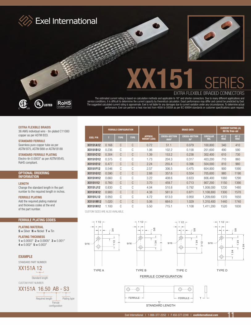
EXTRA FLEXIBLE BRAIDS36 AWG individual wire - tin-plated C11000 copper as per ASTM B33.
STANDARD FERRULESeamless pure copper tube as per ASTM B75, ASTM B88 or ASTM B188
STANDARD FERRULE PLATINGElectro-tin 0.0003" as per ASTM B545, RoHS compliant.
EXTRA FLEXIBLE BRAIDED CONNECTORSThe estimated current rating is based on calculation methods and applicable to 16" and shorter connectors. Due to many different applications and
service conditions, it is difficult to determime the current capacity by theoretical calculation. Exact performance may differ and cannot be predicted by Exel. The suggested calculated current rating is approximate. Exel is not liable for any damages due to current variation under any circumstances. To determine actual
perfomance, Exel can perform a heat rise test from 400A to 5000A as per IEC 60694 standards or customer specifications upon request.
XX151 SERIES
11Exel International I 1-866-377-2252 I F 450-377-2248 I exelinternational.com
EXEL P/N T TYPE TYPE APPROX.WEIGHT (LBS)
CROSS-SECTIONmm2
CROSS-SECTIONin2
CIRCULARMIL
45° CRISE
CURRENT RATING (A)60 Hz free-air
65° CRISE
BRAID DATA FERRULE CONFIGURATION
XX151A12 0.168 C C 0.72 51.1 0.079 100,800 340 410
XX151B12 0.236 C C 1.06 102.2 0.158 201,600 490 590
XX151C12 0.304 C C 1.39 153.2 0.238 302,400 610 730
XX151D12 0.375 C C 1.73 204.3 0.317 403,200 710 860
XX151E12 0.477 C C 2.24 255.4 0.396 504,000 810 980
XX151F12 0.546 C C 2.57 306.5 0.475 604,800 900 1090
XX151G12 0.590 C C 2.88 357.6 0.554 705,600 980 1190
XX151H12 0.660 C C 3.22 408.6 0.633 806,400 1060 1290
XX151I12 0.760 C C 3.70 459.7 0.713 907,200 1150 1390
XX151J12 0.830 C C 4.04 510.8 0.792 1,008,000 1230 1480
XX151K12 0.900 C C 4.38 561.9 0.871 1,108,800 1300 1570
XX151L12 0.950 C C 4.72 613.0 0.950 1,209,600 1370 1650
XX151M12 1.020 C C 5.06 664.0 1.029 1,310,400 1440 1740
XX151N12 1.100 C C 5.50 715.1 1.108 1,411,200 1520 1830
CUSTOM SIZES ARE ALSO AVAILABLE.
Plating type

SERIES
FERRULE PLATING CODES
OPTIONAL ORDERING INFORMATION
PLATING MATERIALS = Silver N = Nickel T = Tin
PLATING THICKNESS1 = 0.0003" 2 = 0.0005" 3 = 0.001" 4 = 0.002" 5 = 0.003"
EXAMPLESTANDARD PART NUMBER
X163A 12
CUSTOM PART NUMBER
X163A 16.50 AB - S3
LENGTHChange the standard length in the part number to the required length in inches.
FERRULE PLATINGAdd the required plating material and thickness codes at the end of the part number.
STANDARD FLEXIBLE BRAIDS30 AWG individual wire - tin-plated C11000 copper as per ASTM B33.
STANDARD FERRULESeamless pure copper tube as per ASTM B75, ASTM B88 or ASTM B188
STANDARD FERRULE PLATINGElectro-tin 0.0003" as per ASTM B545, RoHS compliant.
FLEXIBLE BRAIDED CONNECTORSThe estimated current rating is based on calculation methods and applicable to 16" and shorter connectors. Due to many different applications and
service conditions, it is difficult to determime the current capacity by theoretical calculation. Exact performance may differ and cannot be predicted by Exel. The suggested calculated current rating is approximate. Exel is not liable for any damages due to current variation under any circumstances. To determine actual
perfomance, Exel can perform a heat rise test from 400A to 5000A as per IEC 60694 standards or customer specifications upon request.
X163 SERIES
12 Exel International I 1-866-377-2252 I F 450-377-2248 I exelinternational.com
EXEL P/N T TYPE TYPE APPROX.WEIGHT (LBS)
CROSS-SECTIONmm2
CROSS-SECTIONin2
CIRCULARMIL
45° CRISE
CURRENT RATING (A)60 Hz free-air
65° CRISE
BRAID DATA FERRULE CONFIGURATION
X163A12 0.165 C C 0.74 53.5 0.083 105,600 360 430
X163B12 0.231 C C 1.09 107.0 0.166 211,200 510 620
X163C12 0.330 C C 1.44 160.5 0.249 316,800 620 770
X163D12 0.396 C C 1.96 214.0 0.332 422,400 750 910
X163E12 0.463 C C 2.32 267.6 0.415 528,000 850 1030
X163F12 0.500 C C 2.67 321.1 0.498 633,600 940 1130
X163G12 0.570 C C 2.99 374.6 0.581 739,200 1020 1240
X163H12 0.663 C C 3.35 428.1 0.664 844,800 1110 1340
X163I12 0.729 C C 3.85 481.6 0.746 950,400 1200 1440
X163J12 0.796 C C 4.20 535.1 0.829 1,056,000 1270 1540
X163K12 0.847 C C 4.55 588.6 0.912 1,161,600 1350 1630
X163L12 0.914 C C 4.91 642.1 0.995 1,267,200 1420 1720
X163M12 0.980 C C 5.26 695.7 1.078 1,372,800 1500 1810
X163N12 1.062 C C 5.74 749.2 1.161 1,478,400 1570 1900
CUSTOM SIZES ARE ALSO AVAILABLE.
Plating type

SERIES
FERRULE PLATING CODES
OPTIONAL ORDERING INFORMATION
PLATING MATERIALS = Silver N = Nickel T = Tin
PLATING THICKNESS1 = 0.0003" 2 = 0.0005" 3 = 0.001" 4 = 0.002" 5 = 0.003"
EXAMPLESTANDARD PART NUMBER
XX163A 12
CUSTOM PART NUMBER
XX163A 16.50 AB - S3
LENGTHChange the standard length in the part number to the required length in inches.
FERRULE PLATINGAdd the required plating material and thickness codes at the end of the part number.
EXTRA FLEXIBLE BRAIDS36 AWG individual wire - tin-plated C11000 copper as per ASTM B33.
STANDARD FERRULESeamless pure copper tube as per ASTM B75, ASTM B88 or ASTM B188
STANDARD FERRULE PLATINGElectro-tin 0.0003" as per ASTM B545, RoHS compliant.
EXTRA FLEXIBLE BRAIDED CONNECTORSThe estimated current rating is based on calculation methods and applicable to 16" and shorter connectors. Due to many different applications and
service conditions, it is difficult to determime the current capacity by theoretical calculation. Exact performance may differ and cannot be predicted by Exel. The suggested calculated current rating is approximate. Exel is not liable for any damages due to current variation under any circumstances. To determine actual
perfomance, Exel can perform a heat rise test from 400A to 5000A as per IEC 60694 standards or customer specifications upon request.
XX163 SERIES
13Exel International I 1-866-377-2252 I F 450-377-2248 I exelinternational.com
EXEL P/N T TYPE TYPE APPROX.WEIGHT (LBS)
CROSS-SECTIONmm2
CROSS-SECTIONin2
CIRCULARMIL
45° CRISE
CURRENT RATING (A)60 Hz free-air
65° CRISE
BRAID DATA FERRULE CONFIGURATION
XX163A12 0.162 C C 0.72 51.1 0.079 100,800 350 420
XX163B12 0.225 C C 1.06 102.2 0.158 201,600 500 600
XX163C12 0.321 C C 1.56 153.2 0.238 302,400 620 750
XX163D12 0.384 C C 1.90 204.3 0.317 403,200 730 880
XX163E12 0.448 C C 2.24 255.4 0.396 504,000 830 1000
XX163F12 0.486 C C 2.54 306.5 0.475 604,800 910 1100
XX163G12 0.549 C C 2.88 357.6 0.554 705,600 1000 1210
XX163H12 0.612 C C 3.22 408.6 0.633 806,400 1080 1300
XX163I12 0.702 C C 3.70 459.7 0.713 907,200 1160 1400
XX163J12 0.765 C C 4.04 510.8 0.792 1,008,000 1240 1500
XX163K12 0.829 C C 4.40 561.9 0.871 1,108,800 1310 1580
XX163L12 0.877 C C 4.72 613.0 0.950 1,209,600 1380 1670
XX163M12 0.941 C C 5.06 664.0 1.029 1,310,400 1450 1750
XX163N12 1.020 C C 5.50 715.1 1.108 1,411,200 1530 1840
CUSTOM SIZES ARE ALSO AVAILABLE.
Plating type

SERIES
FERRULE PLATING CODES
OPTIONAL ORDERING INFORMATION
LENGTHChange the standard length in the part number to the required length in inches.
FERRULE PLATINGAdd the required plating material and thickness codes at the end of the part number.
STANDARD FLEXIBLE BRAIDS30 AWG individual wire - tin-plated C11000 copper as per ASTM B33.
STANDARD FERRULESeamless pure copper tube as per ASTM B75, ASTM B88 or ASTM B188
STANDARD FERRULE PLATINGElectro-tin 0.0003" as per ASTM B545, RoHS compliant.
FLEXIBLE BRAIDED CONNECTORSThe estimated current rating is based on calculation methods and applicable to 16" and shorter connectors. Due to many different applications and
service conditions, it is difficult to determime the current capacity by theoretical calculation. Exact performance may differ and cannot be predicted by Exel. The suggested calculated current rating is approximate. Exel is not liable for any damages due to current variation under any circumstances. To determine actual
perfomance, Exel can perform a heat rise test from 400A to 5000A as per IEC 60694 standards or customer specifications upon request.
X175
PLATING MATERIALS = Silver N = Nickel T = Tin
PLATING THICKNESS1 = 0.0003" 2 = 0.0005" 3 = 0.001" 4 = 0.002" 5 = 0.003"
EXAMPLESTANDARD PART NUMBER
X175A 12
CUSTOM PART NUMBER
X175A 16.50 AB - S3
SERIES
14 Exel International I 1-866-377-2252 I F 450-377-2248 I exelinternational.com
EXEL P/N T TYPE TYPE APPROX.WEIGHT (LBS)
CROSS-SECTIONmm2
CROSS-SECTIONin2
CIRCULARMIL
45° CRISE
CURRENT RATING (A)60 Hz free-air
65° CRISE
BRAID DATA FERRULE CONFIGURATION
X175A12 0.190 C C 0.90 53.5 0.083 105,600 370 450
X175B12 0.250 C C 1.25 107.0 0.166 211,200 530 640
X175C12 0.314 C C 1.61 160.5 0.249 316,800 660 790
X175D12 0.353 C C 1.93 214.0 0.332 422,400 760 920
X175E12 0.413 C C 2.28 267.6 0.415 528,000 860 1040
X175F12 0.474 C C 2.64 321.1 0.498 633,600 950 1150
X175G12 0.560 C C 3.14 374.6 0.581 739,200 1050 1260
X175H12 0.625 C C 3.49 428.1 0.664 844,800 1130 1360
X175I12 0.683 C C 3.85 481.6 0.746 950,400 1210 1460
X175J12 0.731 C C 4.20 535.1 0.829 1,056,000 1290 1550
X175K12 0.792 C C 4.56 588.6 0.912 1,161,600 1360 1640
X175L12 0.853 C C 4.91 642.1 0.995 1,267,200 1440 1730
X175M12 0.929 C C 5.38 695.7 1.078 1,372,800 1510 1800
X175N12 1.000 C C 5.73 749.2 1.161 1,478,400 1580 1910
CUSTOM SIZES ARE ALSO AVAILABLE.
Plating type

SERIES
FERRULE PLATING CODES
OPTIONAL ORDERING INFORMATION
PLATING MATERIALS = Silver N = Nickel T = Tin
PLATING THICKNESS1 = 0.0003" 2 = 0.0005" 3 = 0.001" 4 = 0.002" 5 = 0.003"
EXAMPLESTANDARD PART NUMBER
XX175A 12
CUSTOM PART NUMBER
XX175A 16.50 AB - S3
LENGTHChange the standard length in the part number to the required length in inches.
FERRULE PLATINGAdd the required plating material and thickness codes at the end of the part number.
EXTRA FLEXIBLE BRAIDS36 AWG individual wire - tin-plated C11000 copper as per ASTM B33.
STANDARD FERRULESeamless pure copper tube as per ASTM B75, ASTM B88 or ASTM B188
STANDARD FERRULE PLATINGElectro-tin 0.0003" as per ASTM B545, RoHS compliant.
EXTRA FLEXIBLE BRAIDED CONNECTORSThe estimated current rating is based on calculation methods and applicable to 16" and shorter connectors. Due to many different applications and
service conditions, it is difficult to determime the current capacity by theoretical calculation. Exact performance may differ and cannot be predicted by Exel. The suggested calculated current rating is approximate. Exel is not liable for any damages due to current variation under any circumstances. To determine actual
perfomance, Exel can perform a heat rise test from 400A to 5000A as per IEC 60694 standards or customer specifications upon request.
XX175 SERIES
15Exel International I 1-866-377-2252 I F 450-377-2248 I exelinternational.com
EXEL P/N T TYPE TYPE APPROX.WEIGHT (LBS)
CROSS-SECTIONmm2
CROSS-SECTIONin2
CIRCULARMIL
45° CRISE
CURRENT RATING (A)60 Hz free-air
65° CRISE
BRAID DATA FERRULE CONFIGURATION
XX175A12 0.189 C C 0.89 51.1 0.079 100,800 360 440
XX175B12 0.247 C C 1.22 102.2 0.158 201,600 520 620
XX175C12 0.306 C C 1.56 153.2 0.238 302,400 640 770
XX175D12 0.342 C C 1.87 204.3 0.317 403,200 740 900
XX175E12 0.400 C C 2.20 255.4 0.396 504,000 840 1010
XX175F12 0.458 C C 2.54 306.5 0.475 604,800 930 1120
XX175G12 0.541 C C 3.03 357.6 0.554 705,600 1020 1230
XX175H12 0.573 C C 3.27 408.6 0.633 806,400 1100 1320
XX175I12 0.658 C C 3.70 459.7 0.713 907,200 1180 1420
XX175J12 0.703 C C 4.04 510.8 0.792 1,008,000 1250 1510
XX175K12 0.761 C C 4.38 561.9 0.871 1,108,800 1300 1600
XX175L12 0.819 C C 4.72 613.0 0.950 1,209,600 1400 1690
XX175M12 0.892 C C 5.17 664.0 1.029 1,310,400 1470 1770
XX175N12 0.951 C C 5.50 715.1 1.108 1,411,200 1540 1860
CUSTOM SIZES ARE ALSO AVAILABLE.
Plating type
SERIES
FERRULE PLATING CODES
OPTIONAL ORDERING INFORMATION
PLATING MATERIALS = Silver N = Nickel T = Tin
PLATING THICKNESS1 = 0.0003" 2 = 0.0005" 3 = 0.001" 4 = 0.002" 5 = 0.003"
EXAMPLESTANDARD PART NUMBER
X200A 12
CUSTOM PART NUMBER
X200A 16.50 AB - S3
LENGTHChange the standard length in the part number to the required length in inches.
FERRULE PLATINGAdd the required plating material and thickness codes at the end of the part number.
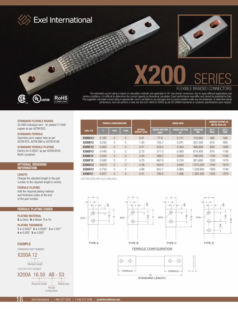
STANDARD FLEXIBLE BRAIDS30 AWG individual wire - tin-plated C11000 copper as per ASTM B33.
STANDARD FERRULESeamless pure copper tube as per ASTM B75, ASTM B88 or ASTM B188
STANDARD FERRULE PLATINGElectro-tin 0.0003" as per ASTM B545, RoHS compliant.
FLEXIBLE BRAIDED CONNECTORSThe estimated current rating is based on calculation methods and applicable to 16" and shorter connectors. Due to many different applications and
service conditions, it is difficult to determime the current capacity by theoretical calculation. Exact performance may differ and cannot be predicted by Exel. The suggested calculated current rating is approximate. Exel is not liable for any damages due to current variation under any circumstances. To determine actual
perfomance, Exel can perform a heat rise test from 400A to 5000A as per IEC 60694 standards or customer specifications upon request.
X200 SERIES
16 Exel International I 1-866-377-2252 I F 450-377-2248 I exelinternational.com
EXEL P/N T TYPE TYPE APPROX.WEIGHT (LBS)
CROSS-SECTIONmm2
CROSS-SECTIONin2
CIRCULARMIL
45° CRISE
CURRENT RATING (A)60 Hz free-air
65° CRISE
BRAID DATA FERRULE CONFIGURATION
X200A12 0.187 C C 0.91 77.8 0.121 153,600 460 560
X200B12 0.235 C C 1.43 155.7 0.241 307,200 670 800
X200C12 0.362 C C 2.21 233.5 0.362 460,800 830 1000
X200D12 0.440 C C 2.72 311.3 0.483 614,400 970 1180
X200E12 0.505 C C 3.24 389.2 0.603 768,000 1100 1330
X200F12 0.582 C C 3.75 467.0 0.724 921,600 1220 1470
X200G12 0.672 C C 4.38 544.8 0.844 1,075,200 1340 1610
X200H12 0.750 C C 4.89 622.7 0.965 1,228,800 1450 1740
X200I12 0.827 C C 5.41 700.5 1.086 1,382,400 1550 1870
CUSTOM SIZES ARE ALSO AVAILABLE.
Plating type

SERIES
FERRULE PLATING CODES
OPTIONAL ORDERING INFORMATION
PLATING MATERIALS = Silver N = Nickel T = Tin
PLATING THICKNESS1 = 0.0003" 2 = 0.0005" 3 = 0.001" 4 = 0.002" 5 = 0.003"
EXAMPLESTANDARD PART NUMBER
XX200A 12
CUSTOM PART NUMBER
XX200A 16.50 AB - S3
LENGTHChange the standard length in the part number to the required length in inches.
FERRULE PLATINGAdd the required plating material and thickness codes at the end of the part number.
EXTRA FLEXIBLE BRAIDS36 AWG individual wire - tin-plated C11000 copper as per ASTM B33.
STANDARD FERRULESeamless pure copper tube as per ASTM B75, ASTM B88 or ASTM B188
STANDARD FERRULE PLATINGElectro-tin 0.0003" as per ASTM B545, RoHS compliant.
EXTRA FLEXIBLE BRAIDED CONNECTORSThe estimated current rating is based on calculation methods and applicable to 16" and shorter connectors. Due to many different applications and
service conditions, it is difficult to determime the current capacity by theoretical calculation. Exact performance may differ and cannot be predicted by Exel. The suggested calculated current rating is approximate. Exel is not liable for any damages due to current variation under any circumstances. To determine actual
perfomance, Exel can perform a heat rise test from 400A to 5000A as per IEC 60694 standards or customer specifications upon request.
XX200 SERIES
17Exel International I 1-866-377-2252 I F 450-377-2248 I exelinternational.com
EXEL P/N T TYPE TYPE APPROX.WEIGHT (LBS)
CROSS-SECTIONmm2
CROSS-SECTIONin2
CIRCULARMIL
45° CRISE
CURRENT RATING (A)60 Hz free-air
65° CRISE
BRAID DATA FERRULE CONFIGURATION
XX200A12 0.187 C C 1.07 102.2 0.158 201,600 540 650
XX200B12 0.235 C C 1.41 153.2 0.238 302,400 660 800
XX200C12 0.335 C C 2.01 204.3 0.317 403,200 780 940
XX200D12 0.384 C C 2.35 255.4 0.396 504,000 880 1060
XX200E12 0.437 C C 2.69 306.5 0.475 604,800 970 1170
XX200F12 0.486 C C 3.05 357.6 0.554 705,600 1050 1270
XX200G12 0.524 C C 3.37 408.6 0.633 806,400 1130 1370
XX200H12 0.575 C C 3.71 459.7 0.713 907,200 1210 1460
XX200I12 0.625 C C 4.04 510.8 0.792 1,008,000 1290 1550
XX200J12 0.740 C C 4.83 613.0 0.950 1,209,600 1430 1730
XX200K12 0.790 C C 5.17 664.0 1.029 1,310,400 1500 1810
XX200L12 0.841 C C 5.50 715.1 1.108 1,411,200 1570 1890
CUSTOM SIZES ARE ALSO AVAILABLE.
Plating type

SERIES
FERRULE PLATING CODES
OPTIONAL ORDERING INFORMATION
PLATING MATERIALS = Silver N = Nickel T = Tin
PLATING THICKNESS1 = 0.0003" 2 = 0.0005" 3 = 0.001" 4 = 0.002" 5 = 0.003"
EXAMPLESTANDARD PART NUMBER
X300A 12
CUSTOM PART NUMBER
X300A 16.50 AB - S3
LENGTHChange the standard length in the part number to the required length in inches.
FERRULE PLATINGAdd the required plating material and thickness codes at the end of the part number.
STANDARD FLEXIBLE BRAIDS30 AWG individual wire - tin-plated C11000 copper as per ASTM B33.
STANDARD FERRULESeamless pure copper tube as per ASTM B75, ASTM B88 or ASTM B188
STANDARD FERRULE PLATINGElectro-tin 0.0003" as per ASTM B545, RoHS compliant.
FLEXIBLE BRAIDED CONNECTORSThe estimated current rating is based on calculation methods and applicable to 16" and shorter connectors. Due to many different applications and
service conditions, it is difficult to determime the current capacity by theoretical calculation. Exact performance may differ and cannot be predicted by Exel. The suggested calculated current rating is approximate. Exel is not liable for any damages due to current variation under any circumstances. To determine actual
perfomance, Exel can perform a heat rise test from 400A to 5000A as per IEC 60694 standards or customer specifications upon request.
X300 SERIES
18 Exel International I 1-866-377-2252 I F 450-377-2248 I exelinternational.com
EXEL P/N T TYPE TYPE APPROX.WEIGHT (LBS)
CROSS-SECTIONmm2
CROSS-SECTIONin2
CIRCULARMIL
45° CRISE
CURRENT RATING (A)60 Hz free-air
65° CRISE
BRAID DATA FERRULE CONFIGURATION
X300A12 0.250 A A 2.14 214.0 0.332 422,400 900 1090
X300B12 0.323 A A 2.85 321.1 0.498 633,600 1120 1350
X300C-12 0.392 A A 3.56 428.1 0.664 844,800 1300 1570
X300D-12 0.461 A A 4.27 535.1 0.829 1,056,000 1470 1770
X300E12 0.530 A A 4.97 642.1 0.995 1,267,200 1620 1950
CUSTOM SIZES ARE ALSO AVAILABLE.
Plating type

SERIES
FERRULE PLATING CODES
OPTIONAL ORDERING INFORMATION
PLATING MATERIALS = Silver N = Nickel T = Tin
PLATING THICKNESS1 = 0.0003" 2 = 0.0005" 3 = 0.001" 4 = 0.002" 5 = 0.003"
EXAMPLESTANDARD PART NUMBER
XX300A 12
CUSTOM PART NUMBER
XX300A 16.50 AB - S3
LENGTHChange the standard length in the part number to the required length in inches.
FERRULE PLATINGAdd the required plating material and thickness codes at the end of the part number.
EXTRA FLEXIBLE BRAIDS36 AWG individual wire - tin-plated C11000 copper as per ASTM B33.
STANDARD FERRULESeamless pure copper tube as per ASTM B75, ASTM B88 or ASTM B188
STANDARD FERRULE PLATINGElectro-tin 0.0003" as per ASTM B545, RoHS compliant.
EXTRA FLEXIBLE BRAIDED CONNECTORSThe estimated current rating is based on calculation methods and applicable to 16" and shorter connectors. Due to many different applications and
service conditions, it is difficult to determime the current capacity by theoretical calculation. Exact performance may differ and cannot be predicted by Exel. The suggested calculated current rating is approximate. Exel is not liable for any damages due to current variation under any circumstances. To determine actual
perfomance, Exel can perform a heat rise test from 400A to 5000A as per IEC 60694 standards or customer specifications upon request.
XX300 SERIES
19Exel International I 1-866-377-2252 I F 450-377-2248 I exelinternational.com
EXEL P/N T TYPE TYPE APPROX.WEIGHT (LBS)
CROSS-SECTIONmm2
CROSS-SECTIONin2
CIRCULARMIL
45° CRISE
CURRENT RATING (A)60 Hz free-air
65° CRISE
BRAID DATA FERRULE CONFIGURATION
XX300A12 0.250 A A 2.08 204.3 0.317 403,200 880 1070
XX300B12 0.313 A A 2.76 306.5 0.475 604,800 1090 1320
XX300C-12 0.375 A A 3.43 408.6 0.633 806,400 1270 1530
XX300D12 0.445 A A 4.11 510.8 0.792 1,008,000 1430 1720
XX300E12 0.511 A A 4.78 613.0 0.950 1,209,600 1580 1900
CUSTOM SIZES ARE ALSO AVAILABLE.
Plating type

SERIES
FERRULE PLATING CODES
OPTIONAL ORDERING INFORMATION
PLATING MATERIALS = Silver N = Nickel T = Tin
PLATING THICKNESS1 = 0.0003" 2 = 0.0005" 3 = 0.001" 4 = 0.002" 5 = 0.003"
EXAMPLESTANDARD PART NUMBER
X400A 12
CUSTOM PART NUMBER
X400A 16.50 AB - S3
LENGTHChange the standard length in the part number to the required length in inches.
FERRULE PLATINGAdd the required plating material and thickness codes at the end of the part number.
STANDARD FLEXIBLE BRAIDS30 AWG individual wire - tin-plated C11000 copper as per ASTM B33.
STANDARD FERRULESeamless pure copper tube as per ASTM B75, ASTM B88 or ASTM B188
STANDARD FERRULE PLATINGElectro-tin 0.0003" as per ASTM B545, RoHS compliant.
FLEXIBLE BRAIDED CONNECTORSThe estimated current rating is based on calculation methods and applicable to 16" and shorter connectors. Due to many different applications and
service conditions, it is difficult to determime the current capacity by theoretical calculation. Exact performance may differ and cannot be predicted by Exel. The suggested calculated current rating is approximate. Exel is not liable for any damages due to current variation under any circumstances. To determine actual
perfomance, Exel can perform a heat rise test from 400A to 5000A as per IEC 60694 standards or customer specifications upon request.
X400 SERIES
20 Exel International I 1-866-377-2252 I F 450-377-2248 I exelinternational.com
EXEL P/N T TYPE TYPE APPROX.WEIGHT (LBS)
CROSS-SECTIONmm2
CROSS-SECTIONin2
CIRCULARMIL
45° CRISE
CURRENT RATING (A)60 Hz free-air
65° CRISE
BRAID DATA FERRULE CONFIGURATION
X400A12 0.230 A A 2.77 214.0 0.332 422,400 1000 1210
X400B12 0.250 A A 3.12 255.4 0.396 504,000 1100 1320
X400C12 0.280 A A 3.41 311.3 0.483 614,400 1210 1470
X400D12 0.320 A A 4.04 394.0 0.611 777,600 1370 1650
X400E-12 0.336 A A 4.18 428.1 0.664 844,800 1430 1730
X400F-12 0.354 A A 4.52 467.0 0.724 921,600 1500 1810
X400G12 0.375 A A 4.81 510.8 0.792 1,008,000 1570 1890
X400H12 0.438 A A 5.68 642.1 0.995 1,267,200 1770 2130
X400I12 0.500 A A 6.58 778.4 1.206 1,536,000 1960 2360
X400J12 0.763 A A 10.27 1,284.3 1.991 2,534,400 2570 3100
X400K12 0.841 A A 11.33 1,444.8 2.239 2,851,200 2740 3310
CUSTOM SIZES ARE ALSO AVAILABLE.
Plating type
SERIES
FERRULE PLATING CODES
OPTIONAL ORDERING INFORMATION
PLATING MATERIALS = Silver N = Nickel T = Tin
PLATING THICKNESS1 = 0.0003" 2 = 0.0005" 3 = 0.001" 4 = 0.002" 5 = 0.003"
EXAMPLESTANDARD PART NUMBER
X600A 12
CUSTOM PART NUMBER
X600A 16.50 AB - S3
LENGTHChange the standard length in the part number to the required length in inches.
FERRULE PLATINGAdd the required plating material and thickness codes at the end of the part number.
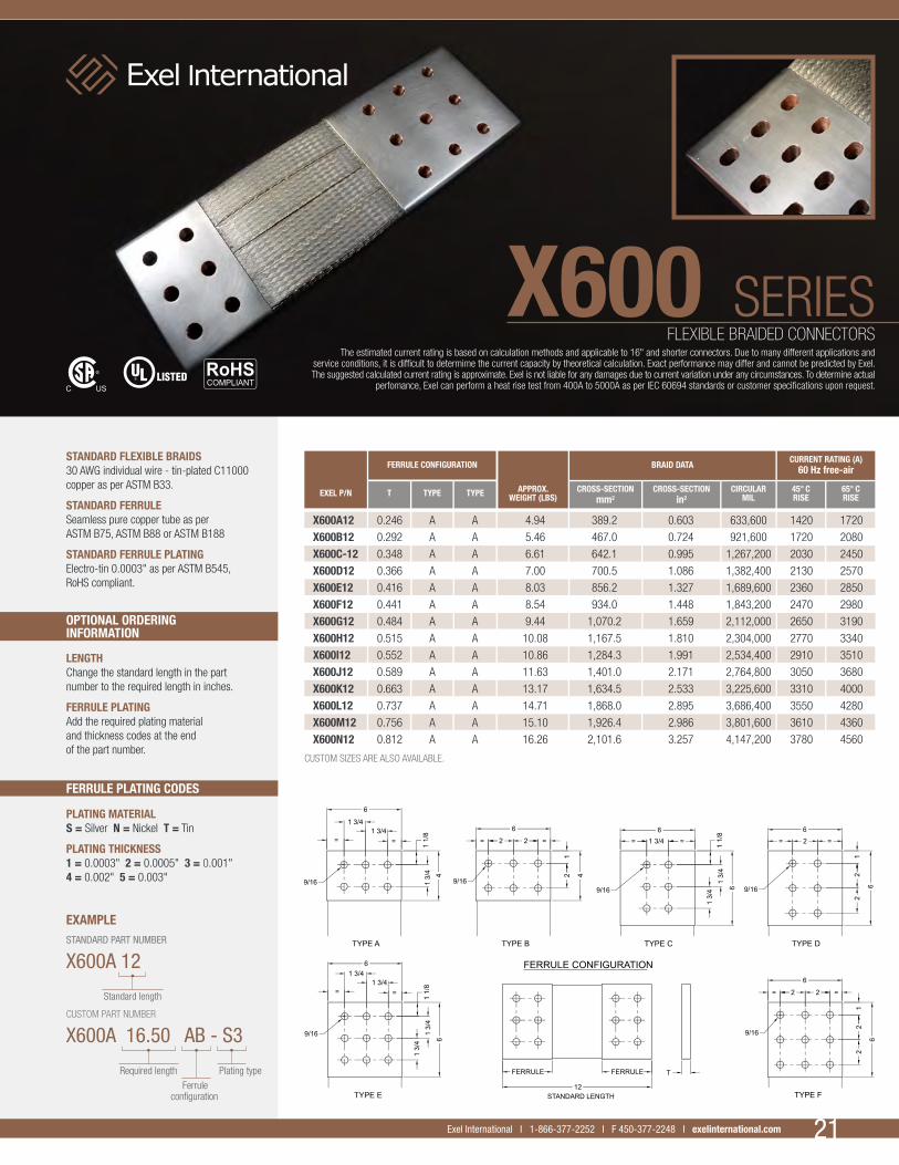
STANDARD FLEXIBLE BRAIDS30 AWG individual wire - tin-plated C11000 copper as per ASTM B33.
STANDARD FERRULESeamless pure copper tube as per ASTM B75, ASTM B88 or ASTM B188
STANDARD FERRULE PLATINGElectro-tin 0.0003" as per ASTM B545, RoHS compliant.
FLEXIBLE BRAIDED CONNECTORSThe estimated current rating is based on calculation methods and applicable to 16" and shorter connectors. Due to many different applications and
service conditions, it is difficult to determime the current capacity by theoretical calculation. Exact performance may differ and cannot be predicted by Exel. The suggested calculated current rating is approximate. Exel is not liable for any damages due to current variation under any circumstances. To determine actual
perfomance, Exel can perform a heat rise test from 400A to 5000A as per IEC 60694 standards or customer specifications upon request.
X600 SERIES
21Exel International I 1 866 377-2252 I F 450 377-2248 I exelinternational.com 21Exel International I 1-866-377-2252 I F 450-377-2248 I exelinternational.com
EXEL P/N T TYPE TYPE APPROX.WEIGHT (LBS)
CROSS-SECTIONmm2
CROSS-SECTIONin2
CIRCULARMIL
45° CRISE
CURRENT RATING (A)60 Hz free-air
65° CRISE
BRAID DATA FERRULE CONFIGURATION
X600A12 0.246 A A 4.94 389.2 0.603 633,600 1420 1720
X600B12 0.292 A A 5.46 467.0 0.724 921,600 1720 2080
X600C-12 0.348 A A 6.61 642.1 0.995 1,267,200 2030 2450
X600D12 0.366 A A 7.00 700.5 1.086 1,382,400 2130 2570
X600E12 0.416 A A 8.03 856.2 1.327 1,689,600 2360 2850
X600F12 0.441 A A 8.54 934.0 1.448 1,843,200 2470 2980
X600G12 0.484 A A 9.44 1,070.2 1.659 2,112,000 2650 3190
X600H12 0.515 A A 10.08 1,167.5 1.810 2,304,000 2770 3340
X600I12 0.552 A A 10.86 1,284.3 1.991 2,534,400 2910 3510
X600J12 0.589 A A 11.63 1,401.0 2.171 2,764,800 3050 3680
X600K12 0.663 A A 13.17 1,634.5 2.533 3,225,600 3310 4000
X600L12 0.737 A A 14.71 1,868.0 2.895 3,686,400 3550 4280
X600M12 0.756 A A 15.10 1,926.4 2.986 3,801,600 3610 4360
X600N12 0.812 A A 16.26 2,101.6 3.257 4,147,200 3780 4560
CUSTOM SIZES ARE ALSO AVAILABLE.
Plating type

22Exel International I 1 866 377-2252 I F 450 377-2248 I exelinternational.com
THE BRAIDED COPPER CABLES SHOWN ON THIS PAGE ARE THE MOST COMMONLY USED IN THE INDUSTRY. THEY ARE EITHER TIN-PLATED OR BARE COPPER. SILVER AND NICKEL PLATING ARE ALSO AVAILABLE.
Wires are made of C11000 soft-annealed copper.
TIN-PLATED COPPER BRAIDRaw material meets ASTM B33.
BARE COPPER BRAIDRaw material meets ASTM B3.
NICKEL-PLATED COPPER BRAIDRaw material meets ASTM B355.
SILVER-PLATED COPPER BRAIDRaw material meets ASTM B298.
If bare copper is required, add (B) at the end of the part number.
When nickel-plated copper is required, add (N) at the end of the part number.
When silver-plated copper is required, add (S) at the end of the part number.
All dimensions are approximate and for reference only.
BRAIDED COPPER CABLES
22 Exel International I 1-866-377-2252 I F 450-377-2248 I exelinternational.com
FBC40-48-86 1.000 0.060 40 48 X 86 40,700 4 140.0
FBC36-24-7 0.250 0.030 36 24 X 7 4,200 14 14.0
FBC36-24-16 0.375 0.063 36 24 X 16 9,600 11 32.0
FBC36-48-15 0.625 0.040 36 48 X 15 18,000 8 61.2
FBC36-24-40 0.500 0.094 36 24 X 40 24,000 7 75.2
FBC36-26-67 0.750 0.094 36 26 X 67 40,200 4 142.7
FBC36-48-40 1.000 0.094 36 48 X 40 48,000 4 163.0
FBC36-48-84 1.625 0.080 36 48 X 84 100,800 1 359.0
FBC30-24-10 0.500 0.094 30 24 X 10 24,120 6 85.0
FBC30-24-16 0.625 0.094 30 24 X 16 38,400 4 125.0
FBC30-24-20 0.750 0.110 30 24 X 20 48,000 4 170.0
FBC30-24-27 0.937 0.130 30 24 X 27 64,800 2 225.0
FBC30-24-32 1.000 0.140 30 24 X 32 76,800 1 270.0
FBC30-24-44 1.250 0.125 30 24 X 44 105,600 1/O 362.0
FBC30-48-22 1.375 0.125 30 48 X 22 105,600 1/O 362.0
FBC30-48-32 2.000 0.140 30 48 X 32 153,600 3/O 530.0
FBC30-48-52 2.500 0.190 30 48 X 52 249,600 250 MCM 900.0
FBC30-2-24-32 1.250 0.290 30 2 X 24 X 32 153,600 3/O 560.0
FBC30-2-24-35 1.250 0.300 30 2 X 24 X 35 168,000 3/O 600.0
FBC30-3-24-32 1.250 0.400 30 3 X 24 X 32 230,400 4/O 825.0
FBC30-4-24-32 1.375 0.510 30 4 X 24 X 32 307,200 300 MCM 1,110.0
OTHER SIZES ARE ALSO AVAILABLE.
EXEL PART NUMBER
EXTR
A FL
EXIB
LE
FLAT
BRA
IDST
ANDA
RD F
LEXI
BLE
FLAT
BRA
IDM
ULTI
-LAY
ER
FLAT
BRA
ID
NOMINAL FLAT WIDTH (IN)
NOMINAL THICKNESS (IN)
INDIVIDUAL AWG CONSTRUCTION
TOTAL CIRCULAR
MIL
APPROX. AWG
EQUIVALENT
APPROX. WEIGHT (LBS/1000 FT)
RLC36-7-7-43 0.339 36 7 x 7 x 43 52,675 3 169.0
RLC30-7-7-34 0.605 30 7 x 7 x 34 167,601 3/O 538.0
RLC36-19-7-64 0.690 36 19 x 7 x 64 212,800 4/O 689.0
RLC30-7-7-43 0.681 30 7 x 7 x 43 211,966 4/O 680.0
OTHER SIZES ARE ALSO AVAILABLE.
ROPE
-LAY
RO
UND
BRAI
D
EXEL PART NUMBER
NOMINAL DIAMETER (IN)
INDIVIDUAL AWG CONSTRUCTION
TOTAL CIRCULAR
MIL
APPROX. AWG
EQUIVALENT
APPROX. WEIGHT (LBS/1000 FT)

23Exel International I 1 866 377-2252 I F 450 377-2248 I exelinternational.com 23Exel International I 1-866-377-2252 I F 450-377-2248 I exelinternational.com
STANDARD WIRE GAUGES
STANDARD NOMINAL DIAMETERS AND CROSS-SECTIONAL AREAS OF SOLID ROUND WIRES AT 20° C AS PER ASTM B258
AWG No
WIRE DIAMETERCIRCULAR MILS
INCH MM
4/0 0.4600 11.684 211,600
3/0 0.4096 10.404 167,800
2/0 0.3648 9.266 133,100
1/0 0.3248 8.250 105,600
1 0.2893 7.348 83,690
2 0.2576 6.543 66,360
3 0.2294 5.827 52,620
4 0.2043 5.189 41,740
5 0.1819 4.620 33,090
6 0.1620 4.115 26,240
7 0.1443 3.665 20,820
8 0.1285 3.264 16,510
9 0.1144 2.906 13,090
10 0.1019 2.588 10,380
11 0.0907 2.304 8,230
12 0.0808 2.052 6,530
13 0.0720 1.829 5,180
14 0.0641 1.628 4,110
15 0.0571 1.450 3,260
16 0.0508 1.290 2,580
17 0.0453 1.150 2,050
18 0.0403 1.024 1,620
19 0.0359 0.912 1,290
20 0.0320 0.812 1,020
21 0.0285 0.723 812
22 0.0253 0.643 640
23 0.0226 0.573 511
24 0.0201 0.511 404
25 0.0179 0.455 320
26 0.0159 0.405 253
27 0.0142 0.361 202
28 0.0126 0.321 159
29 0.0113 0.286 128
30 0.0100 0.255 100
31 0.0089 0.226 79.2
32 0.0080 0.203 64.0
33 0.0071 0.180 50.4
34 0.0063 0.160 39.7
35 0.0056 0.142 31.4
36 0.0050 0.127 25.0
37 0.0045 0.114 20.2
38 0.0040 0.102 16.0
39 0.0035 0.0889 12.2
40 0.0031 0.0787 9.61
41 0.0028 0.0711 7.84
42 0.0025 0.0635 6.25
43 0.0020 0.0508 4.84
44 0.0020 0.0508 4.00

ELECTRICAL COMPONENTS

APPLICATIONS
Frequently used for electrical connections in extreme conditions and environments, laminated connectors are mainly used in the following circumstances:
• Low mechanical vibrations • Minor thermal contraction and/or expansion of attached units • Low movements • Space constraints
If vibration is a critical factor, we suggest using flexible braided connectors.
SPECIFICATIONS
LAMINATES
• Tin-plated C11000 ETP copper as per ASTM B33 • Silver-plated C11000 ETP copper as per ASTM B298 • Nickel-plated C11000 copper as per ASTM B355 • Bare C11000 ETP copper as per ASTM B152 • Aluminium alloy 1350 as per ASTM B209
Standard laminates vary in thickness from 0.005" to 0.04" and in width from 0.5" to 10".
PLATING OPTIONS FOR CONTACT PADS
• Electrolytic tin plating as per ASTM B545 • Electrolytic silver plating as per ASTM B700 • Electroless nickel plating as per ASTM B733 • Lead-free hot-dip tin plating
The standard plating thickness on a contact pad is 0.0003" although it can reach 0.004", upon customer’s request.
OVERALL DIMENSIONS
• Contact pad widths up to 10" • Contact pad thicknesses up to 3" • Total connector lengths up to 72" • Mounting holes in accordance with NEMA standards
Custom sizes are also available.
CURRENT CAPACITY
• 100 amperes to 7,500 amperes, according to design specifications
OPTIONS
• Insulation: Heat shrink PVC and polyolefin, ceramic heat shield and several other types of insulation materials are available.
If flexible braided connectors don’t meet customer needs, flexible laminated copper and aluminium connectors can provide an alternative. Manufactured according to unsurpassed internal procedures, they offer a solution that meets the highest
quality standards. Designed so they can be tailored to customer’s specifications, the laminated connectors are then manufactured by a team of keen experts.
LAMINATED COPPER AND ALUMINIUM CONNECTORS
LC004 LC005 LC006
LC001
LC002 LC003
27Exel International I 1-866-377-2252 I F 450-377-2248 I exelinternational.com

MATERIALS
Materials known for their conductivity properties are C11000 ETP copper and aluminium alloys 1350 and 6061. Other alloys can be used upon request.
PLATING OPTIONS
• Electrolytic tin plating as per ASTM B545 • Electrolytic silver plating as per ASTM B700 • Electroless nickel plating as per ASTM B733
FABRICATION CAPABILITIES
• Widths up to 60" • Thicknesses up to 3" • Lengths up to 240" • Mounting holes as per NEMA standards or customer specifications
CURRENT CAPACITY
Current capacity is determined according to assembly configuration and bus dimension. In some cases, current capacity can reach over 50,000 A.
OPTIONS
• Insulation: Heat shrink PVC and polyolefin, ceramic heat shield material and other types of insulation materials are available. • Epoxy powder-coated bus bar insulation available
Parts are manufactured with proprietary equipment employing cutting edge technology designed by Exel. Primarily used to conduct electricity from one fixed contact to another,
Exel bus bar assemblies demonstrate flawless quality and reliability.
COPPER AND ALUMINIUM BUS BARS
BB001
28 Exel International I 1-866-377-2252 I F 450-377-2248 I exelinternational.com
BB002 BB003 BB004
BB005 BB006 BB007
COPPER VS ALUMINIUM RATIOS
FEATURE COPPER ALUMINIUM
WEIGHT AT SAME CONDUCTIVITY 1 0.50SECTION AT SAME CONDUCTIVITY 1 1.30CONDUCTIVITY AT SAME SECTION 1 0.61TRACTION RESISTANCE 1 0.40HARDNESS 1 0.44MODULUS OF ELASTICITY 1 0.55COEFFICIENT OF THERMAL EXPANSION 1 1.39MELTING POINT 1 0.61COST AT SAME WEIGHT 1 0.60

29Exel International I 1-866-377-2252 I F 450-377-2248 I exelinternational.com
RECTANGULAR BAR COPPER C11000
AREA WEIGHT60-Hz CURRENT RATING (Amp) INDOOR SERVICE, 40° C AMBIENT,
SINGLE BAR HORIZONTAL RUN ON EDGE, FREE OF EXTERNAL MAGNETIC INFLUENCES, SKIN EFFECT RATIO OF 1.00 TO 1.70
THICK WIDTH SQ. IN SQ. MM MCM LBS/FT 30° C RISE* 40° C RISE 50° C RISE 65° C RISE
0.125 0.500 0.063 40.3 80 0.242 153 176 203 2370.125 0.750 0.094 60.5 119 0.363 215 247 285 333
0.125 1.000 0.125 80.6 159 0.485 270 311 358 419
0.125 1.500 0.188 121.0 239 0.727 385 443 510 597
0.125 2.000 0.250 161.3 318 0.969 495 569 656 767
0.125 2.500 0.313 201.6 398 1.211 600 690 795 930
0.125 3.000 0.375 241.9 477 1.454 710 817 941 1,101
0.125 3.500 0.438 282.3 557 1.696 810 932 1,073 1,256
0.125 4.000 0.500 322.6 637 1.938 910 1,047 1,206 1,411
0.250 0.500 0.125 80.6 159 0.485 240 276 318 372
0.250 0.750 0.188 121.0 239 0.727 320 368 424 496
0.250 1.000 0.250 161.3 318 0.969 400 460 530 620
0.250 1.500 0.375 241.9 477 1.454 560 644 742 868
0.250 2.000 0.500 322.6 637 1.938 710 817 941 1,101
0.250 2.500 0.625 403.2 796 2.423 850 978 1,126 1,318
0.250 3.000 0.750 483.9 955 2.907 990 1,139 1,312 1,535
0.250 3.500 0.875 564.5 1,114 3.392 1,150 1,323 1,524 1,783
0.250 4.000 1.000 645.2 1,273 3.876 1,250 1,438 1,656 1,938
0.250 5.000 1.250 806.5 1,592 4.845 1,500 1,725 1,988 2,325
0.250 6.000 1.500 967.7 1,910 5.814 1,750 2,013 2,319 2,713
0.375 0.750 0.281 181.5 358 1.090 415 477 550 643
0.375 1.000 0.375 241.9 477 1.454 510 587 676 791
0.375 1.500 0.563 362.9 716 2.180 710 817 941 1,101
0.375 2.000 0.750 483.9 955 2.907 880 1,012 1,166 1,364
0.375 2.500 0.938 604.8 1,194 3.634 1,050 1,208 1,391 1,628
0.375 3.000 1.125 725.8 1,432 4.361 1,200 1,380 1,590 1,860
0.375 3.500 1.313 846.8 1,671 5.087 1,350 1,553 1,789 2,093
0.375 4.000 1.500 967.7 1,910 5.814 1,500 1,725 1,988 2,325
0.375 5.000 1.875 1,209.7 2,387 7.268 1,800 2,070 2,385 2,790
0.375 6.000 2.250 1,451.6 2,865 8.721 2,100 2,415 2,783 3,255
0.375 8.000 3.000 1,935.5 3,820 11.628 2,650 3,048 3,511 4,108
0.500 1.000 0.500 322.6 637 1.938 620 713 822 961
0.500 1.500 0.750 483.9 955 2.907 830 955 1,100 1,287
0.500 2.000 1.000 645.2 1,273 3.876 1,000 1,150 1,325 1,550
0.500 2.500 1.250 806.5 1,592 4.845 1,200 1,380 1,590 1,860
0.500 3.000 1.500 967.7 1,910 5.814 1,400 1,610 1,855 2,170
0.500 3.500 1.750 1,129.0 2,228 6.783 1,550 1,783 2,054 2,403
0.500 4.000 2.000 1,290.3 2,546 7.752 1,700 1,955 2,253 2,635
0.500 5.000 2.500 1,612.9 3,183 9.690 2,050 2,358 2,716 3,178
0.500 6.000 3.000 1,935.5 3,820 11.628 2,400 2,760 3,180 3,720
0.500 8.000 4.000 2,580.6 5,093 15.504 3,000 3,450 3,975 4,650
0.750 4.000 3.000 1,935.5 3,820 11.628 2,050 2,358 2,716 3,178
0.750 5.000 3.750 2,419.4 4,775 14.535 2,400 2,760 3,180 3,720
0.750 6.000 4.500 2,903.2 5,730 17.442 2,800 3,220 3,710 4,340
0.750 8.000 6.000 3,871.0 7,639 23.256 3,500 4,025 4,638 5,425
0.750 10.000 7.500 4,838.7 9,549 29.070 4,200 4,830 5,565 6,510
0.750 12.000 9.000 5,806.4 11,459 34.884 4,900 5,635 6,493 7,595
*Rating of 30°C rise is based on CDA publication.
Notes:1- Approximate AC current rating for multiple bars, spaced ¼ apart shall be: No. of bars Multiply single bar rating by: 2 (II) 1.58 3 (III) 2.00 4 (IIII) 2.30
2- Horizontal capacity is 10% lower than vertical capacity (horizontal run on edge).
3- For aluminium bar capacity, please contact our sales departement.
CURRENT RATINGS

APPLICATIONS
The hybrid bus duct system is usually designed for interconnecting power transformers and other related equipment, such as switchgears and inverters.
SPECIFICATIONS
• Hybrid bus duct systems can be designed to meet the requirements of industry standards.
• Ratings from 400 A to 5000 A, 3 phases, 60 Hz• Ventilated or completely enclosed steel
enclosure with powder-coating paint for indoor or outdoor service with 1000 hours salt-spray resistance.
• Tin or silver-plated copper and aluminium conductors will be used as intermediate bus.
• Flexible braided connectors are used for end-to-end connections, thermal expansion bonding and grounding.
• The systems can include gaskets, connection flanges, wall entrance seals, equipment terminations, tap boxes, offsets, wall supports and structural steel supports as per the specified design.
AVAILABLE SYSTEM TESTING
• Testing to UL 857 and CSA C22.2 No.27 standards or other requirements.
• Heat rise testing.• Short-circuit resistance strength testing
at rated voltage. • Verification of insulation resistance and
dielectric resistance after exposure to rain.• Verification of dielectric voltage resistance. • Verification of impact strength. • Maximum resistance between exposed metal
and busway.
Required tests can be performed by a third-party organization.
Exel International designs and manufactures customized hybrid bus duct systems. Exel offers a wide array of custom-engineered bus duct solutions for the power generation,
distribution, petro-chemical, municipal, transit and industrial markets.
CUSTOM-DESIGNED HYBRID BUS DUCT SYSTEMS
XBD002
XBD001
30 Exel International I 1-866-377-2252 I F 450-377-2248 I exelinternational.com

MATERIALS USED
• C11000 copper • C1300 aluminium • C1350 aluminium • C6061 aluminium • C260 brass • C360 brass
Other materials can be used upon request.
CONTACT MATERIALSSILVER AND COPPER• 90% silver, 10% copper
SILVER AND TUNGSTEN
• 50% tungsten, 50% silver • 65% tungsten, 35% silver • 78% tungsten, 22% silver
COPPER AND TUNGSTEN
• 56% tungsten, 44% copper • 68% tungsten, 32% copper • 70% tungsten, 30% copper • 75% tungsten, 25% copper • 80% tungsten, 20% copper
PLATING OPTIONS
• Electrolytic tin plating as per ASTM B545 • Electrolytic silver plating as per ASTM B700 • Electroless nickel plating as per ASTM B733
WELDING METHODS
• Tungsten-electrode inert gas (TIG) welding • Metal inert gas (MIG) welding • Metal-arc welding • Resistance welding • Brazing (silver)
A brazed electrical contact is a machined part onto which a silver plate is welded. Exel can design entirely new contacts, repair damaged parts, or even visit your site to determine the solution that best meets your needs.
BRAZED ELECTRICAL CONTACTS
BC010 BC011 BC012
BC007 BC008 BC009
BC004 BC005 BC006
BC002 BC003
BC001
31Exel International I 1-866-377-2252 I F 450-377-2248 I exelinternational.com

COATING / PLATINGFOR ELECTRICAL CONDUCTORS
Exel International I 1 866 377-2252 I F 450 377-2248 I exelinternational.comExel International (Contacts Électriques Exel inc) I 1 866 377-2252 I F 450 377-2248 I exelinternational.com
COATING / PLATING FOR ELECTRICAL CONDUCTORS
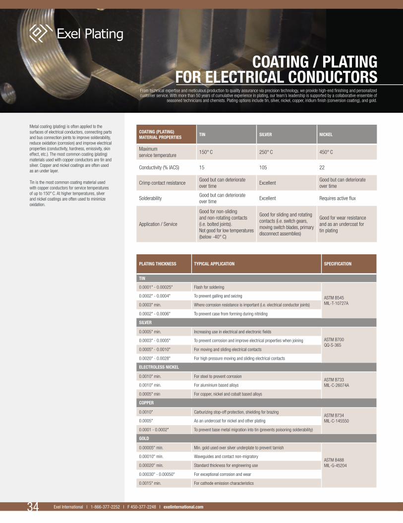
Metal coating (plating) is often applied to the surfaces of electrical conductors, connecting parts and bus connection joints to improve solderability, reduce oxidation (corrosion) and improve electrical properties (conductivity, hardness, emissivity, skin effect, etc.). The most common coating (plating) materials used with copper conductors are tin and silver. Copper and nickel coatings are often used as an under layer.
Tin is the most common coating material used with copper conductors for service temperatures of up to 150° C. At higher temperatures, silver and nickel coatings are often used to minimize oxidation.
COATING (PLATING) MATERIAL PROPERTIES
TIN SILVER NICKEL
Maximum service temperature
150° C 250° C 450° C
Conductivity (% IACS) 15 105 22
Crimp contact resistanceGood but can deteriorate over time
ExcellentGood but can deteriorate over time
SolderabilityGood but can deteriorate over time
Excellent Requires active flux
Application / Service
Good for non-sliding and non-rotating contacts (i.e. bolted joints). Not good for low temperatures (below -40° C)
Good for sliding and rotating contacts (i.e. switch gears, moving switch blades, primary disconnect assemblies)
Good for wear resistance and as an undercoat for tin plating
PLATING THICKNESS TYPICAL APPLICATION SPECIFICATION
TIN
0.0001" - 0.00025" Flash for soldering
ASTM B545MIL-T-10727A
0.0002" - 0.0004" To prevent galling and seizing
0.0003" min. Where corrosion resistance is important (i.e. electrical conductor joints)
0.0002" - 0.0006" To prevent case from forming during nitriding
SILVER
0.0005" min. Increasing use in electrical and electronic fields
ASTM B700QQ-S-365
0.0003" - 0.0005" To prevent corrosion and improve electrical properties when joining
0.0005" - 0.0010" For moving and sliding electrical contacts
0.0020" - 0.0028" For high pressure moving and sliding electrical contacts
ELECTROLESS NICKEL
0.0010" min. For steel to prevent corrosionASTM B733MIL-C-26074A0.0010" min. For aluminium based alloys
0.0005" min For copper, nickel and cobalt based alloys
COPPER
0.0010" Carburizing stop-off protection, shielding for brazingASTM B734MIL-C-1455500.0005" As an undercoat for nickel and other plating
0.0001 - 0.0002" To prevent base metal migration into tin (prevents poisoning solderability)
GOLD
0.00005" min. Min. gold used over silver underplate to prevent tarnish
ASTM B488MIL-G-45204
0.00010" min. Waveguides and contact non-migratory
0.00020" min. Standard thickness for engineering use
0.00030" - 0.00050" For exceptional corrosion and wear
0.0015" min. For cathode emission characteristics
34 Exel International I 1-866-377-2252 I F 450-377-2248 I exelinternational.com
From technical expertise and meticulous production to quality assurance via precision technology, we provide high-end finishing and personalized customer service. With more than 50 years of cumulative experience in plating, our team’s leadership is supported by a collaborative ensemble of
seasoned technicians and chemists. Plating options include tin, silver, nickel, copper, iridium finish (conversion coating), and gold.

35Exel International I 1-866-377-2252 I F 450-377-2248 I exelinternational.com
QUALITY CONTROL:
Measurement of coating thickness by X-ray spectrophotometry
ASTM B568
Qualitative adhesion testing of metallic coating
ASTM B571
Solderability of metallic coated products
ASTM B678
COATING (PLATING) IN SERVICE CONDITION
TEMPERATURE LIMITS AS PER IEC 60694
TEMPERATURE REACHED° C (θ max.)
TEMPERATURE RISE AT 40° C AMBIENT°C (ΔT max.)
CONTACTS (BREAKERS, SWITCHGEAR, ETC.)
BARE COPPER OR BARE-COPPER ALLOY
- In air 75 35
- In SF6 (oxygen-free gas) 105 65
- In oil 80 40
SILVER COATING ON COPPER OR COPPER ALLOY
- In air 105 65
- In SF6 (oxygen-free gas) 105 65
- In oil 90 50
TIN COATING ON COPPER OR COPPER ALLOY
- In air 90 50
- In SF6 (oxygen-free gas) 90 50
- In oil 90 50
BOLTED JOINTS
BARE COPPER OR BARE-COPPER ALLOY
- In air 90 50
- In SF6 (oxygen-free gas) 115 75
- In oil 100 60
SILVER COATING ON COPPER OR COPPER ALLOY
- In air 115 75
- In SF6 (oxygen-free gas) 115 75
- In oil 100 60
TIN COATING ON COPPER OR COPPER ALLOY
- In air 105 65
- In SF6 (oxygen-free gas) 105 65
- In oil 100 60
PL001 PL002
PL003 PL004

CAPABILITIES
Exel can test electrical components either supplied by our customers or manufactured by Exel in the generation, transmission, and distribution of power from hydroelectric, wind, solar and other sources.
TESTING RATIONALE
To avoid premature component degradation or the triggering of a disastrous chain reaction, it is essential to carry out full-scale tests and measurements within conditions that simulate operating life. Moreover, keep in mind that:
1- COMPUTATION IS NOT SUFFICIENT.
Mathematical computation and software programs can provide a useful baseline for theoretical performance. Overlooked or deliberately neglected parameters will lead to a predicted heat rise that, in fact, may be a few degrees from standard. That discrepancy can put your entire electrical apparatus at risk.
2- THE COMPONENT IS PART OF A CRITICAL APPARATUS.
To evaluate the level of criticality, assess the consequences of loss of function, replacement time, and replacement cost.
3- REAL-LIFE OPERATING CONDITIONS ARE HIGHLY VARIABLE.
Environmental factors like temperature and humidity are among the factors that impact component performance.
4- CUSTOM COMPONENTS HAVE NO PERFORMANCE HISTORY.
Testing ensures that a newly designed or modified component is optimized to reduce costs and increase operational life.
Exel International I 1 866 377-2252 I F 450 377-2248 I exelinternational.comExel International (Contacts Électriques Exel inc) I 1 866 377-2252 I F 450 377-2248 I exelinternational.com36 Exel International I 1-866-377-2252 I F 450-377-2248 I exelinternational.com
Exel’s heat rise testing services offer expert qualification and certification according to industry standards, with a responsive turnaround for results.
HEAT RISE TESTING SERVICE
HR002 HR003
HR001
HR004 HR005

37Exel International I 1-866-377-2252 I F 450-377-2248 I exelinternational.com
OBJECTIVES AND TESTS
• Research new materials, configurations, and geometries
• Diagnose components• Test and certify standard and custom products
NORMS AND STANDARDS
We test to the following standards:
• IEC 60694 and 60129• Hydro-Quebec SN19.1A (heat rise tests)
CAPACITY
• 400 A to 5000 A (single phase 60 Hz)• 14 channels of temperature sensors
for measurement• Fully automatic data acquisition system
AUTOMATION
To perform tests in automated fashion, our laboratory was designed to:
• Permanently control the injection current• Record the temperatures at set intervals• Monitor security anomalies and take action
in the event of a failure• Calculate equation parameters for generating
reports and issuing certifications
PERFORMANCE CERTIFICATION
Tested components meeting standards are issued certifications.
0 500 1000 1500 2000 2500 3000
110
100
90
80
70
60
50
40
30
20
10
0
Current (A)
Tem
pera
ture
(Cel
cius
)
HR006
HR007

TECHNICAL INFORMATION
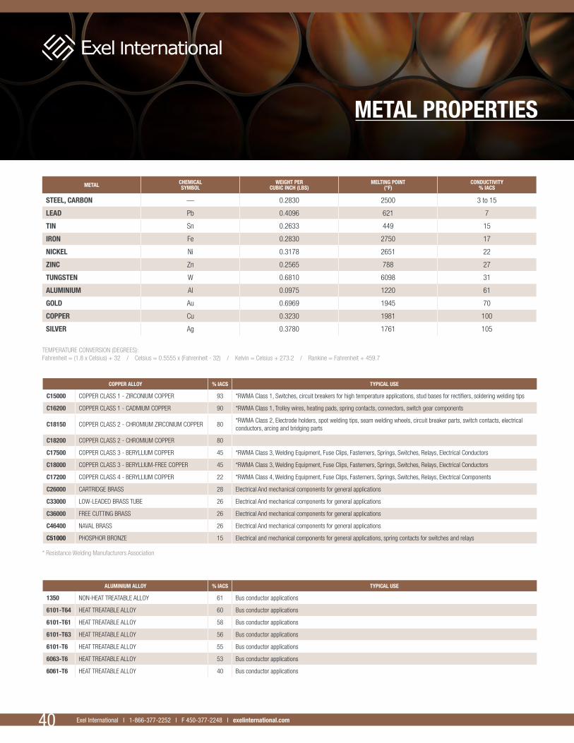
TEMPERATURE CONVERSION (DEGREES):Fahrenheit = (1.8 x Celsius) + 32 / Celsius = 0.5555 x (Fahrenheit - 32) / Kelvin = Celsius + 273.2 / Rankine = Fahrenheit + 459.7
* Resistance Welding Manufacturers Association
METAL PROPERTIES
METAL CHEMICALSYMBOL
WEIGHT PERCUBIC INCH (LBS)
MELTING POINT(°F)
CONDUCTIVITY% IACS
STEEL, CARBON — 0.2830 2500 3 to 15
LEAD Pb 0.4096 621 7
TIN Sn 0.2633 449 15
IRON Fe 0.2830 2750 17
NICKEL Ni 0.3178 2651 22
ZINC Zn 0.2565 788 27
TUNGSTEN W 0.6810 6098 31
ALUMINIUM Al 0.0975 1220 61
GOLD Au 0.6969 1945 70
COPPER Cu 0.3230 1981 100
SILVER Ag 0.3780 1761 105
COPPER ALLOY % IACS TYPICAL USE
C15000 COPPER CLASS 1 - ZIRCONIUM COPPER 93 *RWMA Class 1, Switches, circuit breakers for high temperature applications, stud bases for rectifiers, soldering welding tips
C16200 COPPER CLASS 1 - CADMIUM COPPER 90 *RWMA Class 1, Trolley wires, heating pads, spring contacts, connectors, switch gear components
C18150 COPPER CLASS 2 - CHROMIUM ZIRCONIUM COPPER 80*RWMA Class 2, Electrode holders, spot welding tips, seam welding wheels, circuit breaker parts, switch contacts, electrical conductors, arcing and bridging parts
C18200 COPPER CLASS 2 - CHROMIUM COPPER 80
C17500 COPPER CLASS 3 - BERYLLIUM COPPER 45 *RWMA Class 3, Welding Equipment, Fuse Clips, Fasterners, Springs, Switches, Relays, Electrical Conductors
C18000 COPPER CLASS 3 - BERYLLIUM-FREE COPPER 45 *RWMA Class 3, Welding Equipment, Fuse Clips, Fasterners, Springs, Switches, Relays, Electrical Conductors
C17200 COPPER CLASS 4 - BERYLLIUM COPPER 22 *RWMA Class 4, Welding Equipment, Fuse Clips, Fasterners, Springs, Switches, Relays, Electrical Components
C26000 CARTRIDGE BRASS 28 Electrical And mechanical components for general applications
C33000 LOW-LEADED BRASS TUBE 26 Electrical And mechanical components for general applications
C36000 FREE CUTTING BRASS 26 Electrical And mechanical components for general applications
C46400 NAVAL BRASS 26 Electrical And mechanical components for general applications
C51000 PHOSPHOR BRONZE 15 Electrical and mechanical components for general applications, spring contacts for switches and relays
ALUMINIUM ALLOY % IACS TYPICAL USE
1350 NON-HEAT TREATABLE ALLOY 61 Bus conductor applications
6101-T64 HEAT TREATABLE ALLOY 60 Bus conductor applications
6101-T61 HEAT TREATABLE ALLOY 58 Bus conductor applications
6101-T63 HEAT TREATABLE ALLOY 56 Bus conductor applications
6101-T6 HEAT TREATABLE ALLOY 55 Bus conductor applications
6063-T6 HEAT TREATABLE ALLOY 53 Bus conductor applications
6061-T6 HEAT TREATABLE ALLOY 40 Bus conductor applications
Exel International I 1 866 377-2252 I F 450 377-2248 I exelinternational.comExel International (Contacts Électriques Exel inc) I 1 866 377-2252 I F 450 377-2248 I exelinternational.com40 Exel International I 1-866-377-2252 I F 450-377-2248 I exelinternational.com
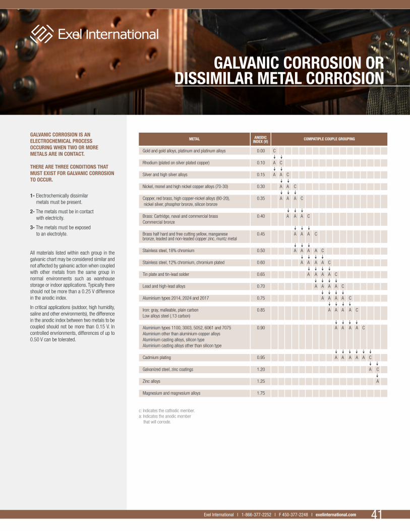
41Exel International I 1 866 377-2252 I F 450 377-2248 I exelinternational.com 41Exel International I 1-866-377-2252 I F 450-377-2248 I exelinternational.com
GALVANIC CORROSION IS AN ELECTROCHEMICAL PROCESS OCCURING WHEN TWO OR MORE METALS ARE IN CONTACT.
THERE ARE THREE CONDITIONS THAT MUST EXIST FOR GALVANIC CORROSION TO OCCUR.
1- Electrochemically dissimilar metals must be present.
2- The metals must be in contact with electricity.
3- The metals must be exposed to an electrolyte.
All materials listed within each group in the galvanic chart may be considered similar and not affected by galvanic action when coupled with other metals from the same group in normal environments such as warehouse storage or indoor applications. Typically there should not be more than a 0.25 V difference in the anodic index.
In critical applications (outdoor, high humidity, saline and other environments), the difference in the anodic index between two metals to be coupled should not be more than 0.15 V. In controlled envrionments, differences of up to 0.50 V can be tolerated.
GALVANIC CORROSION OR DISSIMILAR METAL CORROSION
Gold and gold alloys, platinum and platinum alloys 0.00 C Rhodium (plated on silver plated copper) 0.10 A C Silver and high silver alloys 0.15 A A C Nickel, monel and high nickel copper alloys (70-30) 0.30 A A C Copper, red brass, high copper-nickel alloys (80-20), 0.35 A A A C nickel silver, phosphor bronze, silicon bronze
Brass: Cartridge, naval and commercial brass 0.40 A A A C Commercial bronze
Brass half hard and free cutting yellow, manganese 0.45 A A A C bronze, leaded and non-leaded copper zinc, muntz metal Stainless steel, 18% chromium 0.50 A A A A C
Stainless steel, 12% chromium, chromium plated 0.60 A A A A C
Tin plate and tin-lead solder 0.65 A A A A C
Lead and high-lead alloys 0.70 A A A A C
Aluminium types 2014, 2024 and 2017 0.75 A A A A C
Iron: gray, malleable, plain carbon 0.85 A A A A C Low alloys steel (.13 carbon) Aluminium types 1100, 3003, 5052, 6061 and 7075 0.90 A A A A C Aluminium other than aluminium-copper alloys Aluminium casting alloys, silicon type Aluminium casting alloys other than silicon type
Cadmium plating 0.95 A A A A A C Galvanized steel, zinc coatings 1.20 A C Zinc alloys 1.25 A
Magnesium and magnesium alloys 1.75
c: Indicates the cathodic member.a: Indicates the anodic member that will corrode.
COMPATIPLE COUPLE GROUPINGMETAL ANODICINDEX (V)

Exel International I 1 866 377-2252 I F 450 377-2248 I exelinternational.comExel International (Contacts Électriques Exel inc) I 1 866 377-2252 I F 450 377-2248 I exelinternational.com 042
CONVERSIONS
TEMPERATURE CONVERSION (DEGREES): Fahrenheit = (1.8 x Celsius) + 32
Celsius = 0.5555 x (Fahrenheit - 32)
Kelvin = Celsius + 273.2
Rankine = Fahrenheit + 459.7
42 Exel International I 1-866-377-2252 I F 450-377-2248 I exelinternational.com
MULTIPLY BY TO OBTAIN TO OBTAIN BY DIVIDE
AREA CONVERSIONS
Circular mils 0.0000007854 Square inches
Circular mils 0.0005067 Square millimetres
Square inches 645.16 Square millimetres
Feet 0.3048 Metres
Inches 25.4 Millimetres
Inches 25000 Microns
Miles (U.S.) 1.609344 Kilometres
Yards 0.9144 Metres
Atmosphere 33.9 Feet of water
Atmosphere 29.92 Inch of mercury
Atmosphere 14.7 PSI (pounds/sq. in)
BTU 778.3 Foot-pounds
BTUs per hour 0.2932 Watts
BTUs per minute 0.02356 Horsepower
Gallons (US) 231 Cubic inches
Horsepower 745.7 Watts
Microns 0.00004 Inches
Ounces 0.0625 Pounds
Quarts 0.25 Gallons
Square feet 144 Square inches
Cubic feet 0.02831685 Cubic metres
Gallons (U.S.) 3.785412 Litres
Cubic inches 16387.06 Cubic millimetres
Cubic yards 0.7645549 Cubic metres
Ounces (troy) 31.10348 Grams
Pounds 0.4535924 Kilograms
Tons (2,000 lbs) 907.1847 Kilograms
Tons (metric) 1000 Kilograms
VOLUME CONVERSIONS
MASS AND DENSITY CONVERSIONS
MISCELLANEOUS CONVERSIONS
LENGTH CONVERSIONS

43Exel International I 1 866 377-2252 I F 450 377-2248 I exelinternational.com 43Exel International I 1-866-377-2252 I F 450-377-2248 I exelinternational.com
ASTM SPECIFICATIONS FOR COPPER AND COPPER ALLOY PRODUCTS
ASTM DESCRIPTION ASTM DESCRIPTION
B1 HARD-DRAWN COPPER WIRE B173 ROPE-LAY-STRANDED CONDUCTORS WITH CONCENTRIC STRANDED MEMBERS
B2 MEDIUM-HARD DRAWN COPPER WIRE B174 BUNCH-STRANDED CONDUCTORS
B3 SOFT OR ANNEALED COPPER WIRE B187 COPPER BUS BAR, ROD AND SHAPES
B8 CONCENTRIC-LAY-STRANDED COPPER CONDUCTORS, HARD, MEDIUM-HARD OR SOFT B188 SEAMLESS COPPER BUS PIPE AND TUBE
B16 FREE-CUTTING BRASS ROD, BAR AND SHAPES FOR USE IN SCREW MACHINES B189 LEAD-COATED AND LEAD ALLOY COATED SOFT COPPER WIRE FOR ELECTRICAL PURPOSES
B19 CARTRIDGE BRASS SHEET, STRIP, PLATE, BAR AND DISKS B194 COPPER BERYLLIUM ALLOY PLATE, SHEET, STRIP, AND ROLLED BAR
B21 NAVAL BRASS ROD, BAR AND SHAPES B196 COPPER BERYLLIUM ALLOY ROD AND BAR
B22 BRONZE CASTINGS FOR BRIDGES AND TURNTABLES B197 COPPER BERYLLIUM ALLOY WIRE
B33 TINNED SOFT OR ANNEALED COPPER WIRE FOR ELECTRICAL PURPOSES B226 CORED, ANNULAR, CONCENTRIC-LAY-STRANDED COPPER CONDUCTORS
B36 BRASS PLATE, SHEET, STRIP AND ROLLED BAR B229 CONCENTRIC-LAY-STRANDED COPPER AND COPPER-CLAD STEEL COMPOSITE CONDUCTORS
B42 SEAMLESS COPPER PIPE, STANDARD SIZES B246 TINNED HARD-DRAWN AND MEDIUM HARD-DRAWN COPPER WIRE FOR ELECTRICAL PURPOSES
B43 SEAMLESS RED BRASS PIPE, STANDARD SIZES B258 NOMINAL DIAMETERS AND CROSS-SECTIONAL AREAS OF AWG SIZES OF SOLID ROUND WIRES USED AS ELECTRICAL CONDUCTORS
B48 SOFT RECTANGULAR AND SQUARE BARE COPPER WIRE FOR ELECTRICAL CONDUCTORS B280 SEAMLESS COPPER TUBE FOR AIR CONDITIONING AND REFRIGERATION FIELD SERVICE
B49 HOT-ROLLED COPPER ROD REDRAW FOR ELECTRICAL PURPOSES B286 COPPER CONDUCTORS FOR HOOKUP WIRE IN ELECTRONIC EQUIPMENT
B66 BRONZE CASTINGS IN THE ROUGH FOR LOCOMOTIVE WEARING PARTS B291 COPPER-ZINC-MANGANESE ALLOY (MANGANESE BRASS) SHEET AND STRIP
B68 SEAMLESS COPPER TUBE, BRIGHT ANNEALED B298 SILVER-COATED SOFT OR ANNEALED COPPER WIRE
B75 SEAMLESS COPPER TUBE B301 FREE-CUTTING COPPER ROD AND BAR
B88 SEAMLESS COPPER WATER TUBE B315 SEAMLESS COPPER ALLOY PIPE AND TUBE
B96 COPPER SILICON ALLOY PLATE, SHEET, STRIP AND ROLLED BAR FOR GENERAL PURPOSES AND PRESSURE VESSELS B359 COPPER AND COPPER-ALLOY SEAMLESS CONDENSER AND HEAT EXCHANGER TUBES
WITH INTEGRAL FINS
B98 COPPER-SILICON ALLOY ROD, BAR AND SHAPES B360 HARD-DRAWN COPPER CAPILLARY TUBE FOR RESTRICTOR APPLICATIONS
B99 COPPER-SILICON ALLOY WIRE FOR GENERAL PURPOSES B470 BONDED COPPER CONDUCTORS FOR USE IN HOOKUP WIRE FOR ELECTRONIC EQUIPMENT
B103 PHOSPHOR BRONZE PLATE, SHEET, STRIP AND ROLLED BAR B496 COMPACT ROUND CONCENTRIC-LAY-STRANDED COPPER CONDUCTORS
B105 HARD-DRAWN COPPER ALLOY WIRES FOR ELECTRICAL CONDUCTORS B505 COPPER BASE ALLOY CONTINUOUS CASTINGS
B111 COPPER AND COPPER ALLOY SEAMLESS CONDENSER TUBES AND FERRULE STOCK B584 COPPER ALLOY SAND CASTINGS FOR GENERAL APPLICATIONS
B124 COPPER AND COPPER-ALLOY FORGING ROD, BAR AND SHAPES B624 HIGH-STRENGTH, HIGH-CONDUCTIVITY COPPER ALLOY WIRE FOR ELECTRONIC APPLICATIONS
B133 COPPER ROD, BAR AND SHAPES B638 COPPER AND COPPER ALLOY SOLAR HEAT ABSORBER PANELS
B135 SEAMLESS BRASS TUBE B706 SEAMLESS COPPER ALLOY (UNS NO. C69100) PIPE AND TUBE
B138 MANGANESE BRONZE ROD, BAR AND SHAPES B716 WELDED COPPER WATER TUBE
B139 PHOSPHOR BRONZE ROD, BAR AND SHAPES B738 FINE-WIRE BUNCH-STRANDED AND ROPE-LAY BUNCH STRANDED COPPER CONDUCTORS FOR USE AS ELECTRICAL CONDUCTORS
B140 COPPER-ZINC-LEAD (LEADED RED BRASS HARDWARE BRONZE) ROD, BAR AND SHAPES B743 SEAMLESS COPPER TUBE IN COILS
B150 ALUMINIUM BRONZE ROD, BAR AND SHAPES B747 COPPER-ZIRCONIUM ALLOY SHEET AND STRIP
B152 COPPER SHEET, STRIP, PLATE AND ROLLED BAR F9 ROUND WIRE FOR USE AS GRID SIDE RODS IN ELECTRON TUBES
B159 PHOSPHOR BRONZE WIRE F68 OXYGEN-FREE COPPER IN WROUGHT FORMS FOR ELECTRON DEVICES
B169 ALUMINIUM BRONZE, PLATE, SHEET, STRIP, AND ROLLED BAR F96 ELECTRONIC GRADE ALLOYS OF COPPER IN WROUGHT FORMS
B171 COPPER ALLOY CONDENSER TUBE PLATES F467 NONFERROUS NUTS FOR GENERAL USE
B172 ROPE-LAY-STANDARD CONDUCTORS WITH BUNCH STRANDED MEMBERS F468 NONFERROUS BOLTS, HEX CAP SCREWS, AND STUDS FOR GENERAL USE


EXEL INTERNATIONAL GROUP INC.T 450 377.2252 / 1 866 377.2252
F 450 377.2248 / E [email protected]
exelinternational.com
CA
TALO
G


![Copyright 2015 AIA MasterSpec Premium 03/15 PRODUCT ... · A. Soft Copper Tube: [ASTM B 88, Type K (ASTM B 88M, Type A)] [and] [ASTM B 88, Type L (ASTM B 88M, Type B)], water tube,](https://static.documents.pub/doc/80x56/5b567a1f7f8b9ab7348c8364/copyright-2015-aia-masterspec-premium-0315-product-a-soft-copper-tube.jpg)


