40 mm busbar systems10/6 Introduction10/7 Base assemblies up to 400 A
60 mm busbar systems10/8 Introduction10/9 Base assemblies up to 630 A10/13 Base assemblies up to 1600 A10/14 Infeed and connection methods10/16 Busbar device adapters and
device holders10/23 Connector for 3NP1 fuse switch
disconnectors10/24 Accessories
10/26 Distribution board components
10/28 Built-in components
Busbar Systems
LV10-1_10_EN.book Seite 1 Freitag, 15. Februar 2013 10:25 10
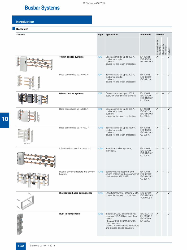
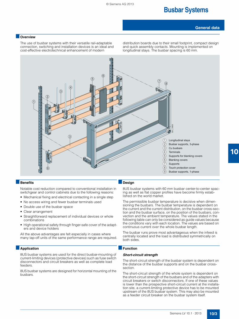
The use of busbar systems with their versatile rail-adaptable connection, switching and installation devices is an ideal and cost-effective electrotechnical enhancement of modern
distribution boards due to their small footprint, compact design and quick assembly contacts. Mounting is implemented on longitudinal stays. The busbar spacing is 60 mm.
■ Benefits
Notable cost reduction compared to conventional installation in switchgear and control cabinets due to the following reasons:• Mechanical fixing and electrical contacting in a single step• No access wiring and fewer busbar terminals used• Double use of the busbar space• Clear arrangement• Straightforward replacement of individual devices or whole
combinations• High operational safety through finger-safe cover of the adapt-
ers and device holders
All the above advantages are felt especially in cases where many tap-off units of the same performance range are required.
■ Application
8US busbar systems are used for the direct busbar-mounting of current-limiting devices (protective devices) such as fuse switch disconnectors and circuit breakers as well as complete load feeders.
8US busbar systems are designed for horizontal mounting of the busbars.
■ Design
8US busbar systems with 60 mm busbar center-to-center spac-ing as well as flat copper profiles have become firmly estab-lished on the world market.
The permissible busbar temperature is decisive when dimen-sioning the busbars. The busbar temperature is dependent on the current and the current distribution, on the busbar cross-sec-tion and the busbar surface, on the position of the busbars, con-vection and the ambient temperature. The values stated in the following table can only be considered as guide values because the conditions vary with each location. The values are based on continuous current over the whole busbar length.
The busbar runs prove most advantageous when the infeed is centrally located and the load is distributed symmetrically on both sides.
■ Function
Short-circuit strength
The short-circuit strength of the busbar system is dependent on the distance of the busbar supports and on the busbar cross-section.
The short-circuit strength of the whole system is dependent on the short-circuit strength of the busbars and of the adapters with circuit breakers or switch disconnectors. If one of these values is lower than the prospective short-circuit current at the installa-tion site, a current-limiting protective device has to be mounted upstream of the 8US busbar system. This may also be mounted as a feeder circuit breaker on the busbar system itself.
Of 8US1 busbar device adapter Current limitation due to associated motor starter protectors/circuit breakers/load feeders up to 50 kA
Of the busbar systems see Characteristic Curves
Material of the 8US1 busbar supports, busbar device adapters and device holders
Glass-fiber reinforced polyamide
Color RAL 7035, light gray
Thermal stability (minimum values)
Busbar supports, busbar device adapters, device holders, infeed and caps
°C 120
AWG connecting cables °C 105 / 150
Cover profiles °C 110
Bases, partitions, edge profiles and blanking covers °C 70
Machining of plastic profiles Take care when machining that no cracks are formed. A cross-cut circular saw with the following characteristic values has proven successful in cutting cover profiles for busbars:
• D = 300 mm, B 0 2.2 mm,
• T = 120 R (5° negative replaceable tooth at a cutting rate of 50 ... 60 m/s,
• tooth feed 0.05 ... 0.1 mm)
The plastic parts are secured so that vibration is ruled out.
Approvals
Busbar supports, busbar device adapters, device holders and terminals
Current carrying capacity of the terminal points A 80 560 300 440The specified current carrying capacities reflect the ther-mal load capability of the terminal points under favorable conditions (with the largest conductors it is possible to connect). This does not invalidate the assignment of con-ductor cross-sections and current carrying capacities as defined in national and international specifications.
Tightening torques Nm -- 30 8 ... 10 12 ... 15
Clamping space W × H mm -- -- 10 × 15 15 × 15
Conductors that can be used mm2 1.5 ... 16 Cu, re, rm, f, f+AE (reduction of the maximum conductor cross-sections may be required)
150 ... 300 Cu, Al (connections with aluminum con-ductors are not main-tenance free), rm, sm, f
6 ... 50 (70) Cu, rm, f, f+AE (reduction of the maximum conductor cross-sections may be required), la. Cu 6 × 9 × 0.8
35 ... 120 Cu, rm, f, f+AE (reduction of the maximum conductor cross-sections may be required), la. Cu 6/10 × 15.5 × 0.8
LV10-1_10_EN.book Seite 4 Freitag, 15. Februar 2013 10:25 10
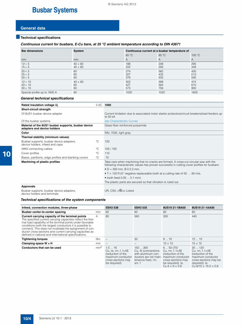
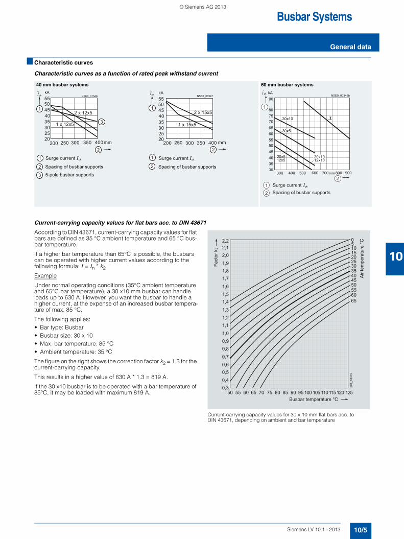
Characteristic curves as a function of rated peak withstand current
Current-carrying capacity values for flat bars acc. to DIN 43671
According to DIN 43671, current-carrying capacity values for flat bars are defined as 35 °C ambient temperature and 65 °C bus-bar temperature.
If a higher bar temperature than 65°C is possible, the busbars can be operated with higher current values according to the following formula: I = In * k2
Example
Under normal operating conditions (35°C ambient temperature and 65°C bar temperature), a 30 x10 mm busbar can handle loads up to 630 A. However, you want the busbar to handle a higher current, at the expense of an increased busbar tempera-ture of max. 85 °C.
The following applies:• Bar type: Busbar • Busbar size: 30 x 10• Max. bar temperature: 85 °C• Ambient temperature: 35 °C
The figure on the right shows the correction factor k2 = 1.3 for the current-carrying capacity.
This results in a higher value of 630 A * 1.3 = 819 A.
If the 30 x10 busbar is to be operated with a bar temperature of 85°C, it may be loaded with maximum 819 A.
Current-carrying capacity values for 30 x 10 mm flat bars acc. to DIN 43671, depending on ambient and bar temperature
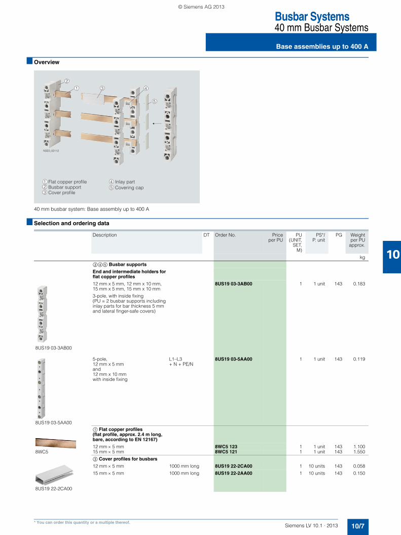
The 40 mm busbar system for the lower performance range up to 400 A Terminals and covers for infeed and connection methods
The 40 mm busbar system is used in machine engineering and distribution boards, in meter cabinets and in power distribution systems of the low performance range up to 400 A.
The busbar cross-sections are adapted to the rated currents and are available in the sizes 12 x 5 mm, 12 x 10 mm, 15 x 5 mm and 15 x 10 mm. The basic system is configured without covers. If touch protection is required, this is possible with busbar covers.
Terminals round off the product range of the 40 mm busbar system.
LV10-1_10_EN.book Seite 6 Freitag, 15. Februar 2013 10:25 10
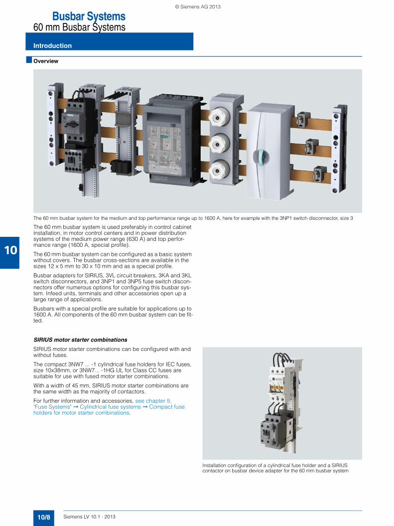
The 60 mm busbar system for the medium and top performance range up to 1600 A, here for example with the 3NP1 switch disconnector, size 3
The 60 mm busbar system is used preferably in control cabinet installation, in motor control centers and in power distribution systems of the medium power range (630 A) and top perfor-mance range (1600 A, special profile).
The 60 mm busbar system can be configured as a basic system without covers. The busbar cross-sections are available in the sizes 12 x 5 mm to 30 x 10 mm and as a special profile.
Busbar adapters for SIRIUS, 3VL circuit breakers, 3KA and 3KL switch disconnectors, and 3NP1 and 3NP5 fuse switch discon-nectors offer numerous options for configuring this busbar sys-tem. Infeed units, terminals and other accessories open up a large range of applications.
Busbars with a special profile are suitable for applications up to 1600 A. All components of the 60 mm busbar system can be fit-ted.
SIRIUS motor starter combinations
SIRIUS motor starter combinations can be configured with and without fuses.
The compact 3NW7 ... -1 cylindrical fuse holders for IEC fuses, size 10x38mm, or 3NW7... -1HG UL for Class CC fuses are suitable for use with fused motor starter combinations.
With a width of 45 mm, SIRIUS motor starter combinations are the same width as the majority of contactors.
For further information and accessories, see chapter 5, "Fuse Systems" ➞ Cylindrical fuse systems ➞ Compact fuse holders for motor starter combinations.
Installation configuration of a cylindrical fuse holder and a SIRIUS contactor on busbar device adapter for the 60 mm busbar system
LV10-1_10_EN.book Seite 8 Freitag, 15. Februar 2013 10:25 10
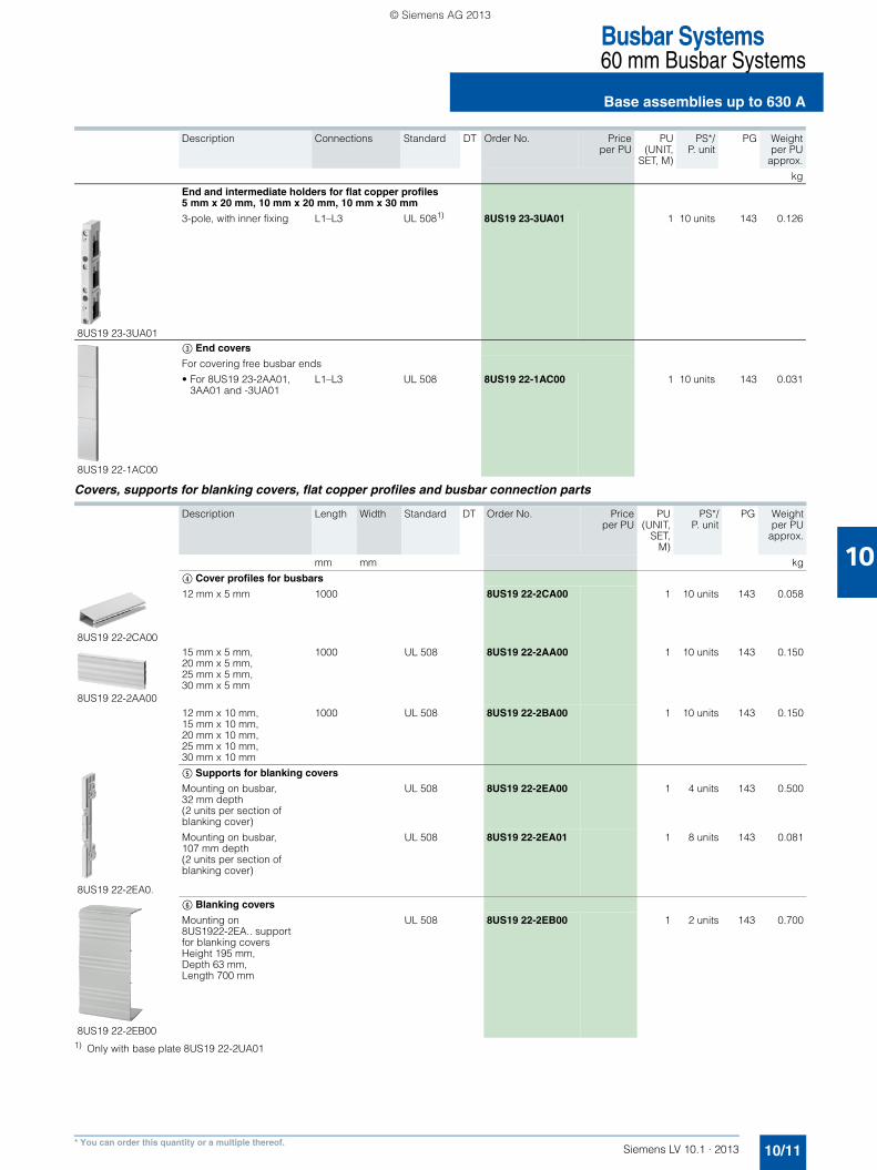
* You can order this quantity or a multiple thereof.
Description Length Cross-section
Standard DT Order No. Priceper PU
PU(UNIT,
SET, M)
PS*/P. unit
PG Weightper PU
approx.
mm mm2 kg
8US19 22-2UA01
Base plates
For 3-pole system, width 230 mm
1100 -- UL 508 8US19 22-2UA01 1 2 units 143 0.575
$ Flat copper profiles (flat profile, bare)
Flat copper profiles for universal applications
• 12 x 5 mm, current intensity 200 A 2400 60 EN 12167 8WC5 123 1 1 unit 143 1.100
• 15 x 5 mm, current intensity 250 A 2400 75 EN 12167 8WC5 121 1 1 unit 143 1.550
• 20 x 5 mm, current intensity 320 A 2400 100 EN 12167 8WC5 126 1 1 unit 143 1.780
• 20 x 5 mm, current intensity 400 A 1100 125 EN 12167 8WC5 031-1AA00 1 1 unit 143 2.240
• 25 x 5 mm, current intensity 400 A 2400 125 EN 12167 8WC5 131 1 1 unit 143 2.240
• 30 x 5 mm, current intensity 447 A 1100 150 EN 12167 8WC5 033-1AA00 1 1 unit 143 2.680
• 30 x 5 mm, current intensity 447 A 2400 150 EN 12167 8WC5 133 1 1 unit 143 2.680
• 20 x 10 mm, current intensity 520 A 2400 200 EN 12167 8WC5 128 1 1 unit 143 3.200
• 30 x 10 mm, current intensity 630 A 2400 300 EN 12167 8WC5 134 1 1 unit 143 5.360
Flat copper profile for ALPHA distribution boards
• 12 x 5 mm, current intensity 250 A 250 60 EN 12167 8GK9 731-0KK10 1 5 units 039 0.100500 60 EN 12167 8GK9 731-0KK20 1 5 units 039 0.330750 60 EN 12167 8GK9 731-0KK30 1 5 units 039 0.500
1000 60 EN 12167 8GK9 731-0KK40 1 5 units 039 0.6601250 60 EN 12167 8GK9 731-0KK50 1 5 units 039 0.830500 60 EN 12167 8GK9 733-0KK20 1 5 units 039 0.570750 60 EN 12167 8GK9 733-0KK30 1 5 units 039 0.850
1000 60 EN 12167 8GK9 733-0KK40 1 5 units 039 1.1201250 60 EN 12167 8GK9 733-0KK50 1 5 units 039 1.470
• 20 x 5 mm, current intensity 320 A 250 100 EN 12167 8GK9 733-0KK10 1 5 units 039 0.290
• 30 x 5 mm, current intensity 447 A 250 150 EN 12167 8GK9 735-0KK10 1 5 units 039 0.400500 150 EN 12167 8GK9 735-0KK20 1 5 units 039 0.750750 150 EN 12167 8GK9 735-0KK30 1 5 units 039 1.460
1000 150 EN 12167 8GK9 735-0KK40 1 5 units 039 2.1701250 150 EN 12167 8GK9 735-0KK50 1 5 units 039 2.880
• 30 x 10 mm, current intensity 630 A 250 300 EN 12167 8GK9 736-0KK10 1 5 units 039 0.750500 300 EN 12167 8GK9 736-0KK20 1 5 units 039 1.720750 300 EN 12167 8GK9 736-0KK30 1 5 units 039 2.600
1000 300 EN 12167 8GK9 736-0KK40 1 5 units 039 3.4001250 300 EN 12167 8GK9 736-0KK50 1 5 units 039 4.600
$ Flat copper profiles, tinned
• 12 x 5 mm, current intensity 200 A 2000 60 EN 12167 8WC5 051 1 1 unit 143 1.100
• 15 x 5 mm, current intensity 250 A 2000 75 EN 12167 8WC5 052 1 1 unit 143 1.550
• 20 x 5 mm, current intensity 320 A 2000 100 EN 12167 8WC5 053 1 1 unit 143 1.780
• 25 x 5 mm, current intensity 400 A 2000 125 EN 12167 8WC5 054 1 1 unit 143 2.240
• 30 x 5 mm, current intensity 447 A 2000 150 EN 12167 8WC5 055 1 1 unit 143 2.680
• 20 x 10 mm, current intensity 520 A 2000 200 EN 12167 8WC5 063 1 1 unit 143 3.200
• 30 x 10 mm, current intensity 630 A 2000 300 EN 12167 8WC5 065 1 1 unit 143 5.360
8JK3 20
Extension terminals
For busbars 12 mm x 5 mm,tightening torque 6.0 Nm(busbar not included, 1 set = 2 units)
-- -- -- 8JK3 201 1 10 set 046 0.020
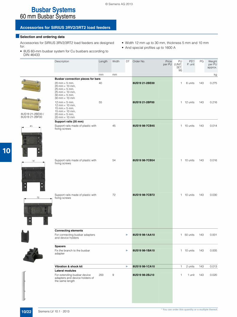
Busbar connection pieces for bars
8US19 21-2BE00
For flat profiles (max. 630 A)20 mm × 5 mm, 20 mm × 10 mm, 25 mm × 5 mm, 25 mm × 10 mm, 30 mm × 5 mm, 30 mm × 10 mm
40 -- -- 8US19 21-2BE00 1 6 units 143 0.275
8US19 21-2BF00
For flat profiles (max. 630 A)12 mm × 5 mm, 12 mm × 10 mm, 15 mm × 5 mm, 15 mm × 10 mm,20 mm × 5 mm, 20 mm × 10 mm
55 -- -- 8US19 21-2BF00 1 12 units 143 0.216
LV10-1_10_EN.book Seite 12 Freitag, 15. Februar 2013 10:25 10
10/15Siemens LV 10.1 · 2013* You can order this quantity or a multiple thereof.
1) Cannot be used on a special profile up to 1600 A. 2) Only for 20 mm × 5 mm, 20 mm × 10 mm, 25 mm × 5 mm, 25 mm × 10 mm, 30 mm × 5 mm and 30 mm × 10 mm.
Description Max.current
Conductor cross-section
Stan-dard
DT Order No. Priceper PU
PU(UNIT,
SET, M)
PS*/P. unit
PG Weightper PU
approx.
mm2 kg
8US19 41-2AA04
Terminal sets
3-pole without coverfor flat bars up to32 x 20 mm
800 UL 508 8US19 41-2AA04 1 1 unit 143 1.377
8US19 22-1GC00
Covers for 8US19 41-2AA03/04 terminal set
8US19 22-1GC00 1 1 unit 143 0.306
Terminals for circular conductors
5 mm busbar thickness1)
Terminals
12 mm × 5 mm, 15 mm × 5 mm, 20 mm × 5 mm, 25 mm × 5 mm, 30 mm × 5 mm
10/16 Siemens LV 10.1 · 2013* You can order this quantity or a multiple thereof.
10
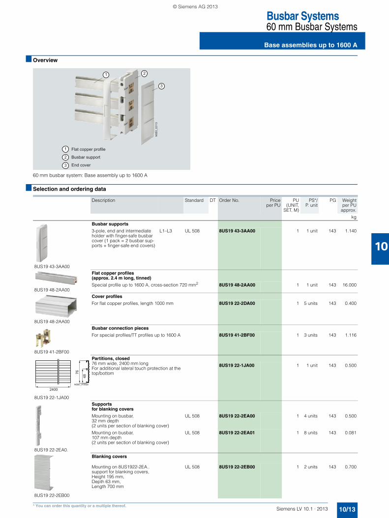
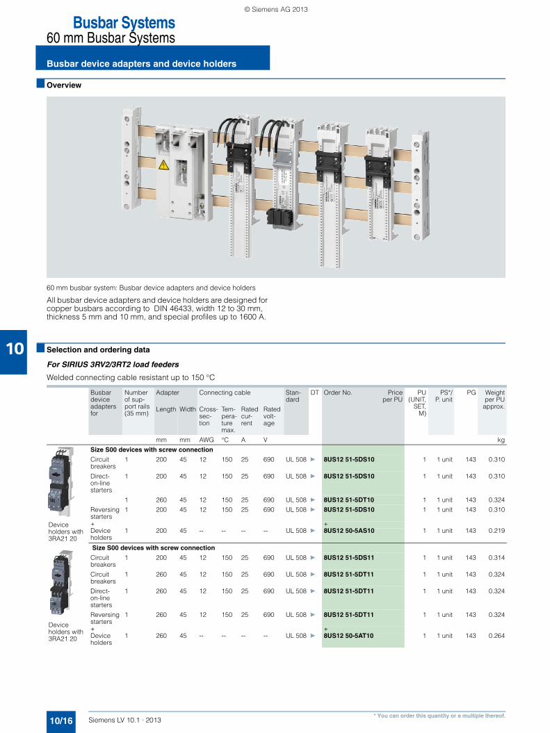
■ Overview
60 mm busbar system: Busbar device adapters and device holders
All busbar device adapters and device holders are designed for copper busbars according to DIN 46433, width 12 to 30 mm, thickness 5 mm and 10 mm, and special profiles up to 1600 A.
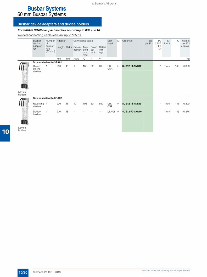
■ Selection and ordering data
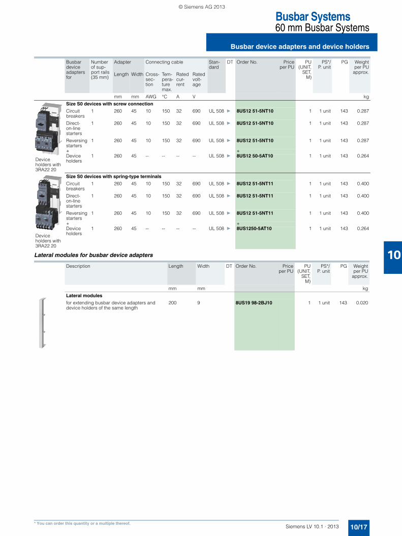
For SIRIUS 3RV2/3RT2 load feeders
Welded connecting cable resistant up to 150 °C
Busbar device adapters for
Number of sup-port rails (35 mm)
Adapter Connecting cable Stan-dard
DT Order No. Priceper PU
PU(UNIT,
SET,M)
PS*/P. unit
PG Weightper PU
approx.Length Width Cross-sec-tion
Tem-pera-turemax.
Rated cur-rent
Rated volt-age
mm mm AWG °C A V kg
Device holders with 3RA21 20
Size S00 devices with screw connection
Circuit breakers
1 200 45 12 150 25 690 UL 508 } 8US12 51-5DS10 1 1 unit 143 0.310
Direct-on-line starters
1 200 45 12 150 25 690 UL 508 } 8US12 51-5DS10 1 1 unit 143 0.310
1 260 45 12 150 25 690 UL 508 } 8US12 51-5DT10 1 1 unit 143 0.324
Reversing starters
1 200 45 12 150 25 690 UL 508 } 8US12 51-5DS10 1 1 unit 143 0.310
+ +Device holders
1 200 45 -- -- -- -- UL 508 } 8US12 50-5AS10 1 1 unit 143 0.219
Device holders with 3RA21 20
Size S00 devices with screw connection
Circuit breakers
1 200 45 12 150 25 690 UL 508 } 8US12 51-5DS11 1 1 unit 143 0.314
Circuit breakers
1 260 45 12 150 25 690 UL 508 } 8US12 51-5DT11 1 1 unit 143 0.324
Direct-on-line starters
1 260 45 12 150 25 690 UL 508 } 8US12 51-5DT11 1 1 unit 143 0.324
Reversing starters
1 260 45 12 150 25 690 UL 508 } 8US12 51-5DT11 1 1 unit 143 0.324
+ +Device holders
1 260 45 -- -- -- -- UL 508 } 8US12 50-5AT10 1 1 unit 143 0.264
LV10-1_10_EN.book Seite 16 Freitag, 15. Februar 2013 10:25 10
10/19Siemens LV 10.1 · 2013* You can order this quantity or a multiple thereof.
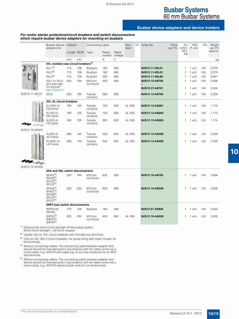
For motor starter protectors/circuit breakers and switch disconnectors which require busbar device adapters for mounting on busbars
1) Observe the short-circuit strength of the busbar system. Short-circuit strength > 50 kA on request.
2) Usable only for 3VL circuit breakers with line-side box terminals.3) Only for 3VL 250 A circuit breakers, for screw fixing with metric thread, for
flat terminals.4) Without connecting cables. The connecting cable between adapter and
device should be manufactured in accordance with the rated current as a round cable, e.g. H07V-R with cable lug, or as a flat conductor for an M10 stud terminal.
5) Without connecting cables. The connecting cable between adapter and device should be manufactured in accordance with the rated current as a round cable, e.g. H07V-R, bared at both ends for tunnel terminals.
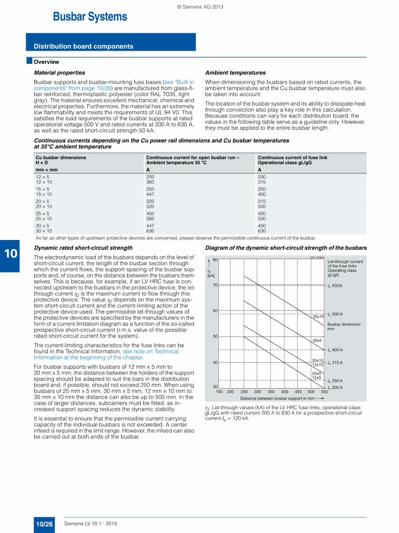
Busbar supports and busbar-mounting fuse bases (see "Built-in components" from page 10/28) are manufactured from glass-fi-ber reinforced, thermoplastic polyester (color RAL 7035, light gray). The material ensures excellent mechanical, chemical and electrical properties. Furthermore, the material has an extremely low flammability and meets the requirements of UL 94 V0. This satisfies the load requirements of the busbar supports at rated operational voltage 500 V and rated currents at 200 A to 630 A, as well as the rated short-circuit strength 50 kA.
Ambient temperatures
When dimensioning the busbars based on rated currents, the ambient temperature and the Cu busbar temperature must also be taken into account.
The location of the busbar system and its ability to dissipate heat through convection also play a key role in this calculation. Because conditions can vary for each distribution board, the values in the following table serve as a guideline only. However, they must be applied to the entire busbar length.
Continuous currents depending on the Cu power rail dimensions and Cu busbar temperatures at 35°C ambient temperature
Dynamic rated short-circuit strength
The electrodynamic load of the busbars depends on the level of short-circuit current, the length of the busbar section through which the current flows, the support spacing of the busbar sup-ports and, of course, on the distance between the busbars them-selves. This is because, for example, if an LV HRC fuse is con-nected upstream to the busbars in the protective device, the let-through current iD is the maximum current to flow through this protective device. The value iD depends on the maximum sys-tem short-circuit current and the current-limiting action of the protective device used. The permissible let-through values of the protective devices are specified by the manufacturers in the form of a current limitation diagram as a function of the so-called prospective short-circuit current (r.m.s. value of the possible rated short-circuit current for the system).
The current-limiting characteristics for the fuse links can be found in the Technical Information, see note on Technical Information at the beginning of the chapter.
For busbar supports with busbars of 12 mm x 5 mm to 20 mm x 5 mm, the distance between the holders of the support spacing should be adapted to suit the bars in the distribution board and, if possible, should not exceed 250 mm. When using busbars of 25 mm x 5 mm, 30 mm x 5 mm, 12 mm x 10 mm to 30 mm x 10 mm the distance can also be up to 500 mm. In the case of larger distances, subcarriers must be fitted, as in-creased support spacing reduces the dynamic stability.
It is essential to ensure that the permissible current carrying capacity of the individual busbars is not exceeded. A center infeed is required in the limit range. However, the infeed can also be carried out at both ends of the busbar.
Diagram of the dynamic short-circuit strength of the busbars
iD: Let-through values (kA) of the LV HRC fuse links, operational class gL/gG with rated current 200 A to 630 A for a prospective short-circuit current Ip = 120 kA.
Cu busbar dimensions H × D
Continuous current for open busbar run – Ambient temperature 35 °C
Continuous current of fuse link Operational class gL/gG
mm × mm A A
12 × 5 200 20012 × 10 360 315
15 × 5 250 25015 × 10 447 400
20 × 5 320 31520 × 10 520 500
25 × 5 400 40025 × 10 580 500
30 × 5 447 40030 × 10 630 630
As far as other types of upstream protective devices are concerned, please observe the permissible continuous current of the busbar.
30
40
50
60
70
80
150 200 250 300 350 400 450 500 550
D[kA]
n 200 A n 250 A
n 315 A
n 400 A
n 500 A
n 630 A
20x512x5
20x1012x10
30x5
30x10
Distance between busbar support in mm
Busbar dimension mm
Let-through current of the fuse linksOperating class gL/gG
I201_07483a
LV10-1_10_EN.book Seite 26 Freitag, 15. Februar 2013 10:25 10
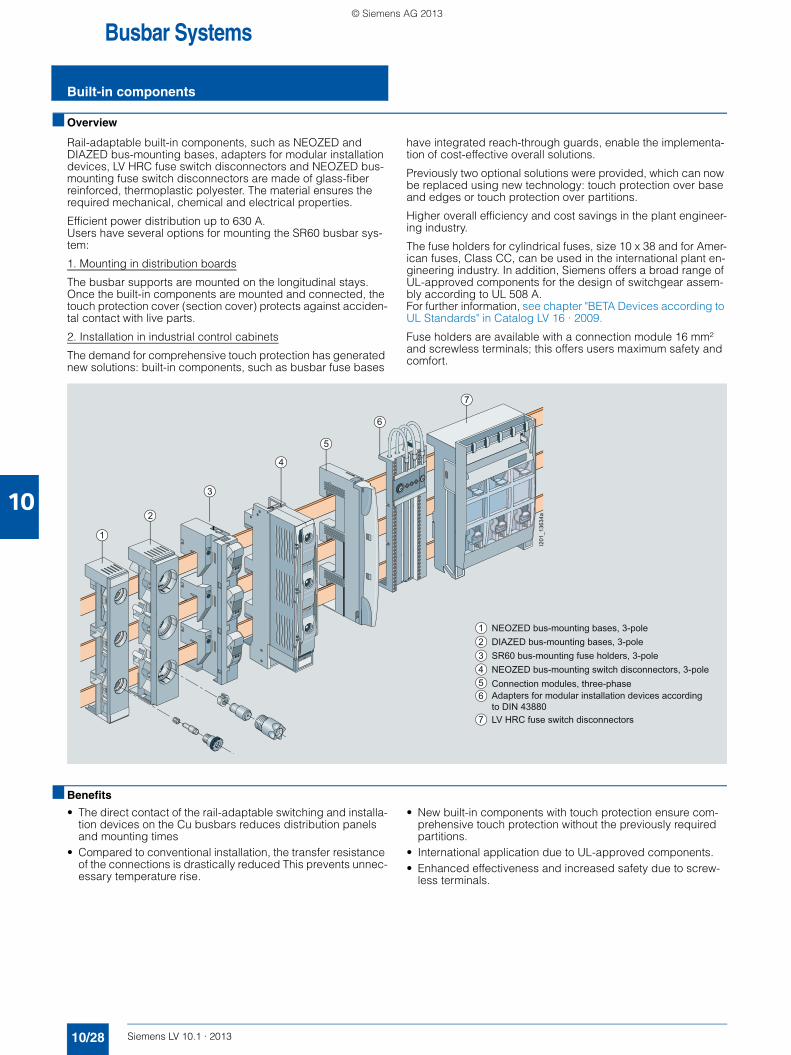
Rail-adaptable built-in components, such as NEOZED and DIAZED bus-mounting bases, adapters for modular installation devices, LV HRC fuse switch disconnectors and NEOZED bus-mounting fuse switch disconnectors are made of glass-fiber reinforced, thermoplastic polyester. The material ensures the required mechanical, chemical and electrical properties.
Efficient power distribution up to 630 A. Users have several options for mounting the SR60 busbar sys-tem:
1. Mounting in distribution boards
The busbar supports are mounted on the longitudinal stays. Once the built-in components are mounted and connected, the touch protection cover (section cover) protects against acciden-tal contact with live parts.
2. Installation in industrial control cabinets
The demand for comprehensive touch protection has generated new solutions: built-in components, such as busbar fuse bases
have integrated reach-through guards, enable the implementa-tion of cost-effective overall solutions.
Previously two optional solutions were provided, which can now be replaced using new technology: touch protection over base and edges or touch protection over partitions.
Higher overall efficiency and cost savings in the plant engineer-ing industry.
The fuse holders for cylindrical fuses, size 10 x 38 and for Amer-ican fuses, Class CC, can be used in the international plant en-gineering industry. In addition, Siemens offers a broad range of UL-approved components for the design of switchgear assem-bly according to UL 508 A.For further information, see chapter "BETA Devices according to UL Standards" in Catalog LV 16 · 2009.
Fuse holders are available with a connection module 16 mm² and screwless terminals; this offers users maximum safety and comfort.
■ Benefits
• The direct contact of the rail-adaptable switching and installa-tion devices on the Cu busbars reduces distribution panels and mounting times
• Compared to conventional installation, the transfer resistance of the connections is drastically reduced This prevents unnec-essary temperature rise.
• New built-in components with touch protection ensure com-prehensive touch protection without the previously required partitions.
• International application due to UL-approved components.• Enhanced effectiveness and increased safety due to screw-
less terminals.
I201
_136
34a
4
5
3
6
7
2
1
NEOZED bus-mounting bases, 3-poleDIAZED bus-mounting bases, 3-poleSR60 bus-mounting fuse holders, 3-poleNEOZED bus-mounting switch disconnectors, 3-poleConnection modules, three-phaseAdapters for modular installation devices according to DIN 43880LV HRC fuse switch disconnectors
123456
7
LV10-1_10_EN.book Seite 28 Freitag, 15. Februar 2013 10:25 10
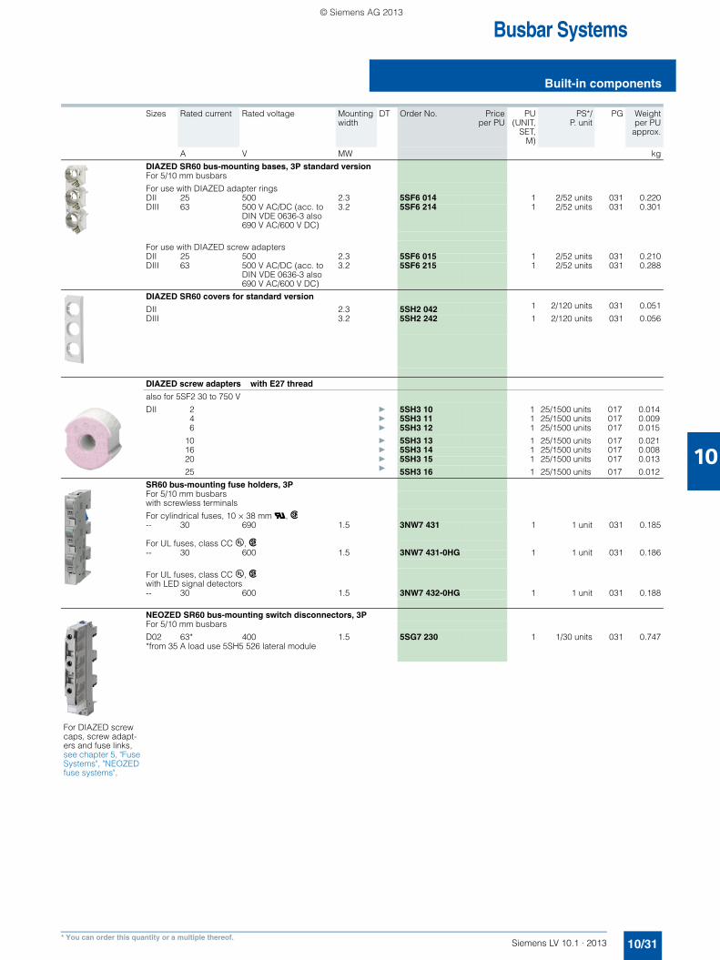
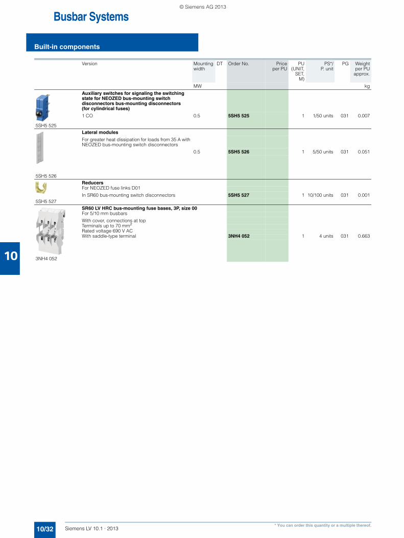
1) In the case of permanent load over 35 A, we recommend the use of 5SH5 526 lateral modules. Please observe EN 60 439-1, Table 1.
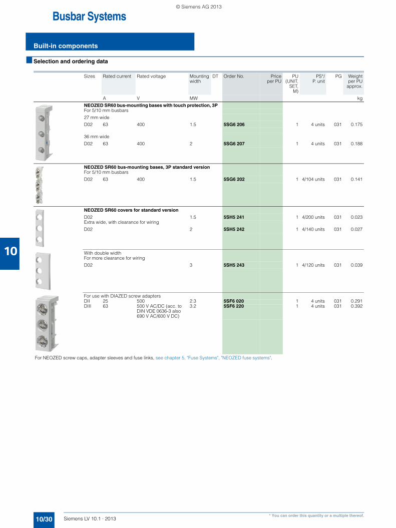
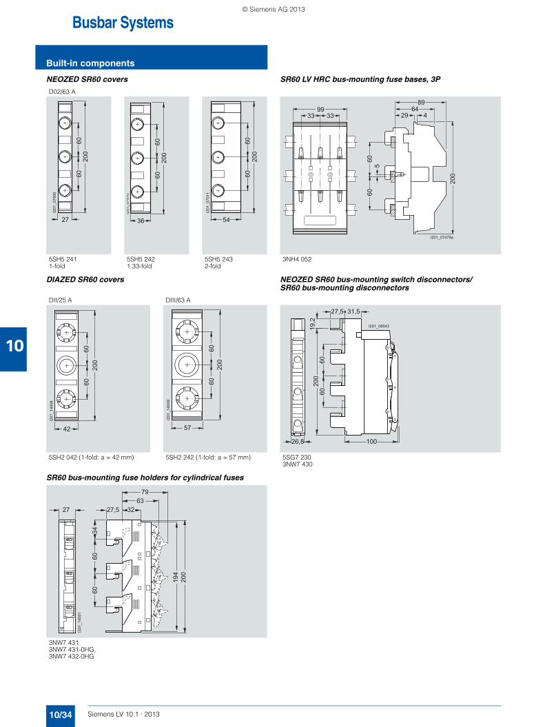
NEOZED SR60 bus-mounting bases
DIAZED SR60 bus-mounting bases
5SG6 202 5SG6 206 5SG6 207
5SF6 014 5SF6 015 5SF6 020
5SF6 214 5SF6 215 5SF6 220
D01 D02 DII DIII
Standards IEC 60269-3
Rated voltage V AC/DC 400/250 500 690/600
Rated frequency Hz 50
Rated current A 16 (with NEOZED retaining springs)
63 25 63
Rated conditional short-circuit current kA AC 50 50kA DC 8 8
For fuse links with power losses per phase W 2.5 5.5 4 7
Busbar center-to-center spacing mm 60 60
3NW7 431 3NW7 431-0HG3NW7 432-0HG
Standards IEC 60269-2, UL 512, CSA C22.2
UL 512, CSA C22.2
Approvals U, CSA UL, CSA
Sizes 10 × 38 Class CC
Rated frequency Hz 50/60
Max. rated voltage Ue• IEC/EN V AC 690 --• UL/CSA V AC 600 600
Max. rated operational current Ie(When several devices are used next to each other, it is essential to comply with the rated load factor according to EN 60439-1, Table 1.)• IEC/EN A 32 --• UL/CSA A 30 30
Utilization categories• IEC/EN AC-22B (500 V)
AC-21B (690 V, 30 A)• UL/CSA Can only be used as fuse holder
Rated conditional short-circuit current(type-tested with fuse links, operational class gL/gG)• IEC/EN kA 100 (400 V, 500 V, 690 V) --• UL/CSA kA 50 (600 V) 200