24
Quick Vision ® CNC Vision Measuring System CATALOG No. E4125-359 Quick Vision ® CNC Vision Measuring System

Quick Vision®
CNC Vision Measuring System
CATALOG No. E4125-359
Quick Vision®
CNC Vision Measuring System

22

3Quick Vision
Mitutoyo Quick Vision® Seriesmoves your vision
measurement and inspectionproductivity to higher levels
with advanced features!
There's a family of powerful visual measuring systems fromMitutoyo. The Quick Vision allows high-speed, highly accurateCNC visual measurement with the state-of-the-art mechanical,
optoelectronics and image processing technologies.
Example of WorkpiecesHybrid chassis, IC chip, lead frame, ICpackage, video cassette electricconnector, etc.
HyperApex
HyperApex
3Quick Vision

4
Quick Vision ELFNormal (E1XY/E1Z): (2.2+3L/1000)µm/ (4+5L/1000)µm
Quick VisionApex (E1XY/E1Z): ((1.5+3L/1000)µm/(3+4L/1000)µmHyper (E1XY/E1Z): (0.8+2L/1000)µm/ (3+2L/1000)µm
Quick Vision HybridApex (E1XY/E1Z): (1.5+3L/1000)µm/ (3+4L/1000)µm
using laser head (E1Z)*: (2.5+4L/1000)µmHyper (E
1XY/E
1Z): (0.8+2L/1000)µm/ (3+2L/1000)µm
using laser head (E1Z)*: (2.5+2L/1000)µm
Mitutoyo offers a great variety of models offering different optical/oblique illumination systems, degrees ofaccuracy and ranges of measurement. The Programmable Ring Light illumination and the Pattern Focusingfunction give you a focused edge even on a mirror-finish surface. Also, the Programmable Power Turret Tube Lens(or Programmable Power Zoom Lens) provides automatic zooming for a wider field of view and a highly detailedimage. At last, you can choose the best visual measuring system for precision workpieces, without the need tocompromise.
Variety of models available
Quick Vision ELF Quick Vision Quick Vision Hybrid
Normal 4 4 4Hyper ––––– 4 4
Quick Vision ELF Quick Vision Quick Vision Hybrid200 4 ––––– –––––
250 4 ––––– –––––
202 ––––– 4 –––––302 ––––– 4 4404 ––––– 4 4606 ––––– 4 4
200x200x100mm (8”x8”x4”)
CHOICE 1: Measuring accuracy
CHOICE 3: Measuring range (XxYxZ)
Linear glass scale with virtually zero thermalexpansion coefficientThe Hyper Quick Vision is equipped with a new crystallizedglass scale having a resolution of 0.02µm and linearexpansion coefficient of 0.08x10⁻⁶/K. This virtually zerothermal expansion coefficient means the Hyper Quick Visioncan minimize accuracy fluctuationresulting from thermal changes.
Standardglass scale
Virtually zerothermal expansionglass scale
200x200x200mm (8”x8”x8”)
200x250x100mm (8”x10”x4”)
300/176*x200x200mm (12”/7”*x8”x8”)
400/276*x400x250mm (16”/11”*x16”x10”)
600/476*x650x250mm (24”/19”*x26”x10”)*using laser head (Quick Vision Hybrid)
Quick Vision ELF
Quick Vision/Quick Vision HybridHyper
ApexHyper
Apex
Most simplified configuration with halogenring-fiber illumination
Quick Vision ELF Quick Vision Quick Vision Hybrid
R/F 4 ––––– –––––
P/T 4 (halogen) 4 (RBG LED) –––––PRO 4 (white LED) 4 (RBG LED) 4 (RBG LED)
Z/M ––––– 4* (halogen) –––––
PRO-II ––––– 4* (halogen) –––––PRO-III ––––– 4* (halogen) –––––
*Not available for Hyper models
CHOICE 2: Oblique illumination system
With programmable power turret tube lensand RGB LED* ring light*Quick Vision ELF: Halogen light
With programmable power turret tube lensand programmable RGB LED* ring light*Quick Vision ELF: White LED
With programmable zoom lens and halogenring-fiber illumination
With programmable power zoom lens andprogrammable halogen ring light
HyperApex
HyperApex
With programmable power turret tube len,programmable halogen ring light and colorCCD camera

5Quick Vision
A retrofit touch-probe system allows youto integrate the touch-probemeasurement function into the QuickVision*. The measurement can becontinued by automatically switching thedetecting sensor from video camera totouch probe and vice versa in CNC mode. The stylus-modulechangeover system is also available to further expand the rangeof measurement application.Mitutoyo offers a special master ball unit and offset ring toproduce a seamless measurement between the video cameraand touch probe in one coordinate system.Note: Not available for Quick Vision Hybrid models
Accessories02ANT850: PH1 set for Quick Vison ELF02ANT860: PH1 set for Quick Vison 202/302/404/60602ANT830: PH6 set for Quick Vison ELF02ANT840: PH6 set for Quick Vison 202/302/404/60602ANL920: Calibration ring02ANT790: Master ball unit for Quick Vision ELF02ANT720: Master ball unit for Quick Vision 20202ANT780: Master ball unit for Quick Vision
302/404/606
PH6 probe head withTP20 touch-signal probe
• Master ball unit with calibration ring• Stylus-module changer (MCR20 rack with 2 or 3 module
ports)
Optional Touch-Probe System
HyperApex
Laser-Probe System
Laser scanning system(for Quick Vision Hybrid)The scanning laser system for the QuickVision Hybrid adds 3-D profiling capability. The laser indicatorwith 0.01µm resolution Laser Holoscale continuously scans theworkpiece surface and records its displacement, enabling theevaluation of surface conditions, contours, peak heights, etc.The double pinholedetection method is adoptedto avoid being affected bythe color, reflection factor,etc. of surface conditions.Additionally, the small laserspot of 1.5µm in diameterensures the accuratemeasurement of fine andintricate contours.
Height measurement of theterminals on the connector
Evaluation result(optional MSHAPE-QV)Tools for laser measurement
Setting of scan conditions
Scanning result (profile viewer)
HyperApex
HyperApex
Laser auto-focus system(factory-set option for Quick Vision)The laser auto-focus system, a built-in laser trigger probe canaccelerate the throughput of Z-axis (height) measurement.Since the TTL visible laserbeam is employed, youcan see a point to befocused with a laserpointer for quickworkpiece positioning.

6
PatternFocusingFunction
CCD camera
Motor
Quadrant RBG LED ring lights** PRO-II: Halogen ring lights
QV ELF: White LED ring lights
Parabolic mirror
Toroidal mirror
Tube lenses
Surface of workpiece
Half-reflectingmirror
Program-mable
Ring Light
Program-mable
Power TurretTube Lens
Pattern Focusing Function
Programmable Power Turret Tube Lens
160x
Edge focusing
Projectedpattern
80x
Mitutoyo Programmable Power Turret Tube Lens provides three-step power zooming for wider field of view and highly detailedimage by switching the internal tube lenses (1x, 2x and 6x).Every time the built-in tube lenses rotate, the pixel size isautomatically calibrated and the light intensity and imageaberration are also adjusted. Furthermore, the ProgrammablePower Turret Tube Lens is absolutely free frommechanical backlash.
Patent pending (Japan)
Patent pending (U.S.A.)
Programmable Power Zoom Lens
In addition to standard Surface and Edge focusing functions,Quick Vision provides one other choice. The Pattern focusingfunction offers the best advantage in focusing on highlyreflective/mirrored, low-contrast/black andtranslucent surfaces. Generally, visual measuringmachines are weak and almost impossible to focuson these surfaces. This function generates andprojects triangular patterns onto the surface to befocused, and the focusing is carried out bytargeting the projected pattern.
16x
240x
Patent pending (Japan)
• Mitutoyo's programmable power zoom lens allowscontinuous measurement in 15 magnification settings from16x to 240x (zoom ratio 1:15) with 92mm (3.6") workingdistance.
• The zoom lens also features a built-in absolute scale. The lensposition is continuously fed back to the controller toreproduce accurate magnification. This not onlyimproves repeatability under differentmagnifications but also provides high-accuracymeasurement, which rivals that of the turretsystem.
480x

7Quick Vision
Front
Left Right
Back
Programmable Ring Light (PRL)
Under ordinary surface illumination– The edge at "A" is not clear.
Under PRL illumination– The edge at "A" can be readily seen.
80°
Quadrant RGB LED ring light*
Toroidal mirror
Parabolic mirror
Surface of workpiece
60°30°
*PRO-II: Halogen ring lights
A
A
Mitutoyo unique 4-quadrant RGB LED*, Programmable RingLight (PRL) allows you to customize part illumination tomaximize its effectiveness. Light intensity in each of four-quadrants is independently controlled. So, you can create themost effective light pattern for the part. A 30° - 80° angle ofincidence lets you create the right amount of shadow formeasuring. *PRO-II: Halogen, QV ELF: White LED
Contourillumination
Surface illumination
• 4-quadrant RGB LED* ring lightThe 4-quadrant RGB LED ring light featured inthe Quick Vision offers effective illumination ofyour workpiece from desired directions,preventing unwanted shadows. The RGB lightcolor control clears the edge problem caused bythe color of your workpiece.*Quick Vision ELF: Halogen ring light
Basic Illuminations
Mixed white
Green
RedBlue
• LED* coaxial light for surface IlluminationThe surface illumination function, standard in all models, isused for the measurement and observation of surfacepatterns. *Quick Vision ELF: Halogen coaxial light
• LED* stage light for contour IlluminationThe contour illumination function, standard in all models, isfor the measurement of frame shape, hole pitch and similarfeatures. *Quick Vision ELF: Halogen stage light
RGB LED Illumination!
Strong in edge detection!
Power saving and long service life!
RGB LED Illumination!
Strong in edge detection!
Power saving and long service life!
8
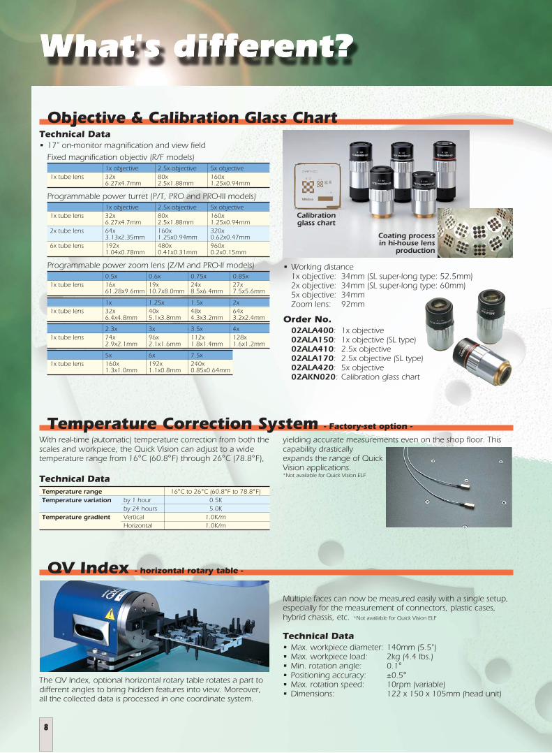
QV Index - horizontal rotary table -
The QV Index, optional horizontal rotary table rotates a part todifferent angles to bring hidden features into view. Moreover,all the collected data is processed in one coordinate system.
Objective & Calibration Glass Chart
Calibrationglass chart
Coating processin hi-house lens
production
With real-time (automatic) temperature correction from both thescales and workpiece, the Quick Vision can adjust to a widetemperature range from 16°C (60.8°F) through 26°C (78.8°F),
Temperature Correction System - Factory-set option -
Technical DataTemperature range 16°C to 26°C (60.8°F to 78.8°F)Temperature variation by 1 hour 0.5K
by 24 hours 5.0KTemperature gradient Vertical 1.0K/m
Horizontal 1.0K/m
Technical Data• 17” on-monitor magnification and view field
Fixed magnification objectiv (R/F models)1x objective 2.5x objective 5x objective
1x tube lens 32x 80x 160x6.27x4.7mm 2.5x1.88mm 1.25x0.94mm
Programmable power turret (P/T, PRO and PRO-III models)1x objective 2.5x objective 5x objective
1x tube lens 32x 80x 160x6.27x4.7mm 2.5x1.88mm 1.25x0.94mm
2x tube lens 64x 160x 320x3.13x2.35mm 1.25x0.94mm 0.62x0.47mm
6x tube lens 192x 480x 960x1.04x0.78mm 0.41x0.31mm 0.2x0.15mm
Programmable power zoom lens (Z/M and PRO-II models)0.5x 0.6x 0.75x 0.85x
1x tube lens 16x 19x 24x 27x61.28x9.6mm 10.7x8.0mm 8.5x6.4mm 7.5x5.6mm
1x 1.25x 1.5x 2x1x tube lens 32x 40x 48x 64x
6.4x4.8mm 5.1x3.8mm 4.3x3.2mm 3.2x2.4mm
2.3x 3x 3.5x 4x1x tube lens 74x 96x 112x 128x
2.9x2.1mm 2.1x1.6mm 1.8x1.4mm 1.6x1.2mm
5x 6x 7.5x1x tube lens 160x 192x 240x
1.3x1.0mm 1.1x0.8mm 0.85x0.64mm
• Working distance1x objective: 34mm (SL super-long type: 52.5mm)2x objective: 34mm (SL super-long type: 60mm)5x objective: 34mmZoom lens: 92mm
Order No.02ALA400: 1x objective02ALA150: 1x objective (SL type)02ALA410: 2.5x objective02ALA170: 2.5x objective (SL type)02ALA420: 5x objective02AKN020: Calibration glass chart
Multiple faces can now be measured easily with a single setup,especially for the measurement of connectors, plastic cases,hybrid chassis, etc. *Not available for Quick Vision ELF
Technical Data• Max. workpiece diameter: 140mm (5.5")• Max. workpiece load: 2kg (4.4 lbs.)• Min. rotation angle: 0.1°• Positioning accuracy: ±0.5°• Max. rotation speed: 10rpm (variable)• Dimensions: 122 x 150 x 105mm (head unit)
yielding accurate measurements even on the shop floor. Thiscapability drasticallyexpands the range of QuickVision applications.*Not available for Quick Vision ELF

9Quick Vision
Traceability System
UKAS:NMi:
NKO:PTB:
DKD:OFMET:
SAS:IMGC:
SIT:INMETRO:
United Kingdom Accreditation ServiceNederlands MeetinstituutNederlandse Kalibratie OrganisatiePhysikalisch-Technische BundesanstaltDeutscher KalibrierdienstSwiss Federal Office of MetrologySwiss Accreditation ServiceIstituto di Metrologia GUSTAVO COLONNETTIServizio di Taratura in ItaliaInstituto Nacional de Metrologia Normalização e Qualidade Industrial
RBC:SIRIM:DSM:NIMT:
TISI:CENAM:
EMA:(ILAC):
(APLAC):(EA):
(MRA):
Rede Brasileira de CalibraçãoStandards and Industrial Research Institute of MalaysiaDepartment of Standards MalaysiaNational Institute of Metrology ThailandThailand Industrial Standard InstituteCentro Nacional de MetrologíaEntidad Mexican de Acreditación, a.c. International Laboratory Accreditation CorperationAsia-Pacific Laboratory Accreditation CorperationEuropean Accreditation CorperationMutual Recognition Agreement
# : Accreditation No.
National Institute of Advanced Industrial Science and TechnologyJapan Calibration Service SystemJapan Quality Assurance OrganizationNational Institute of Technology and EvaluationSingapore Productivity and Standards BoardSingapore Accreditation Council National Measurement LaboratoryChinese National Laboratory AccreditationNational Institute of Standards and TechnologyAmerican Association for Laboratory AccreditationNational Physical Laboratory
AIST:JCSS:JQA:NITE:PSB:SAC:
NML:CNLA:NIST:
A2LA:NPL:
MitutoyoMiyazaki
Plant
# 0030
MitutoyoKiyohara
Plant
# 0067
MitutoyoAsia
Pacific# LA-1996-
0102-C
MitutoyoAmerica
(IL)
# 0750.01
Mitutoyo(UK)
# 0332
MitutoyoMiyazaki
Plant
# K 107
MitutoyoMess
geräte# DKD-K-14501
Mitutoyo Italiana
# 107
Mitutoyo(Malaysia)
# SAMM
152
MitutoyoMexicana
# D-45
MitutoyoTsukuba
Cal.Center
# 0031
MitutoyoUtsunomiyaCal.Center
# 0078
MitutoyoTaiwan
# 0336
MitutoyoAmerica
(MI)
# 1472.01
MitutoyoNederland
# K 086
MitutoyoKawasaki
Cal.Center
# K 125
MitutoyoSchweiz
# SCS074
Mitutoyo Sul
Americana
# 031
MitutoyoThailand
# Calibration
0016
SAC A2LA UKAS RvANKO DKD SAS SIT RBC DSM TISI EMAJQA
AIST
CNLAJCSS
NITE
Japan
PSB
Singapore
NML
Taiwan
NIST
USA
NPL
UK
NMi
TheNetherlands
PTB
Germany
OFMETOFMET
Switzer-land
MGC
Italy
IMMETROIMMETRO
Brazil
SIRIM
Malaysia
NIMT
Thailand
CENAMCENAM
Mexico
EA <MRA>APLAC<MRA>
ILAC<MRA>
OFMET IMMETRO CENAM
AIST633nm lodine Stabilized He-Ne Laser
<National (Primary) Standard>
JQA(Designated Calibration Organization)633nm lodine Stabilized He-Ne Laser<National (Sub-primary) Standard>
Mitutoyo Tsukuba Calibration Center(Accredited Calibration Laboratory No. 0031)
633nm lodine Stabilized He-Ne Laser(Secondary Standard)
Mitutoyo Kiyohara Plant(Accredited Calibration Laboratory No. 0067)
633nm Stabilized He-Ne Laser(Secondary Standard)
Laser Length Measuring Machine(Working Standard)
Reference Gauge Block(Working Standard)
Standard Scale(Working Standard)
Calibration Equipment(Working Standard)
Standard ScaleLaser SourceGauge Block MeasuringInstruments
Once/3 years Once/3 years
Once/3 years
Mitutoyo Utsunomiya Calibration Center(Accredited Calibration Laboratory No. 0078)Standard Gauge Block (Secondary Standard)
Mitutoyo Miyazaki Plant(Accredited Calibration Laboratory No. 0030)
633nm Stabilized He-Ne Laser(Secondary Standard)
Once/2 years
Traceability system oflength standard
Accredited calibration laboratories
Iodine AbsorptionStabilized HE-Ne Laseras the standard forlength measurement (atTsukuba CalibrationCenter)
Interferometer as the standardfor Linear Scale calibration (atthe Kiyohara plant)
Interferometer as thestandard for gaugeblock calibration (at theMiyazaki plant)
Mitutoyo, a manufacturer of precision measuring instruments,offers Quick Vision and a range of other measuring machinesand instruments that are in full compliance with the nationalstandards of various countries. They’re traceable to the nationalstandards through physical standards, which are calibrated viaspecified secondary standards owned by Mitutoyo. Ourcalibration laboratories are accredited to provide calibrationservices in three fields of length-measurement: length-measuring laser units, gauge blocks and linear scales.

10
Quick Vision ELF 200
Hight-price/performance ratio desktop models
• XYZ measuring rangeQVE200: 200 x 200 x 100mm (8" x 8" x 4")QVE250: 200 x 250 x 100mm (10" x 10" x 4")
• Measuring accuracy (E1XY)(2.2+3L/1000)µm
• Resolution0.0001mm
Quick Vision ELF
4
4
4
11Quick Vision
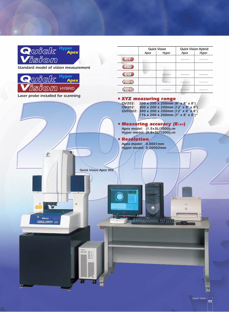
Quick Vision Apex 302
Standard model of vision measurement
Laser probe installed for scanning
HyperApex
HyperApex
• XYZ measuring rangeQV202: 200 x 200 x 200mm (8" x 8" x 8")QV302: 300 x 200 x 200mm (12" x 8" x 8")QVH302: 300 x 200 x 200mm (12" x 8" x 8")
176 x 200 x 200mm (7" x 8" x 8")**using laser head
• Measuring accuracy (E1XY)Apex model: (1.5+3L/1000)µmHyper model: (0.8+2L/1000)µm
• ResolutionApex model: 0.0001mmHyper model: 0.00002mm
Quick Vision Quick Vision HybridApex Hyper Apex Hyper
4 4 ––––– –––––
4 4 4 4
4 ––––– ––––– –––––
4 ––––– ––––– –––––
4 ––––– ––––– –––––

12
Quick Vision Apex 404
Standard model of vision measurement
Laser probe installed for scanning
HyperApex
HyperApex
• XYZ measuring rangeQV404: 400 x 400 x 250mm (16" x 16" x 10")QVH404: 400 x 400 x 250mm (16" x 16" x 10")
276 x 400 x 250mm (11" x 16" x 10")**using laser head
• Measuring accuracy (E1XY)Apex model: (1.5+3L/1000)µmHyper model: (0.8+2L/1000)µm
• ResolutionApex model: 0.0001mmHyper model: 0.00002mm
Quick Vision Quick Vision HybridApex Hyper Apex Hyper
4 4 ––––– –––––
4 4 4 4
4 ––––– ––––– –––––
4 ––––– ––––– –––––
4 ––––– ––––– –––––

13Quick Vision
Quick Vision Apex 606
Standard model of vision measurement
Laser probe installed for scanning
HyperApex
HyperApex
• XYZ measuring rangeQV606: 600 x 650 x 250mm (24" x 26" x 10")QVH606: 600 x 650 x 250mm (24" x 26" x 10")
476 x 650 x 250mm (19" x 26" x 10")**using laser head
• Measuring accuracy (E1XY)Apex model: (1.5+3L/1000)µmHyper model: (0.8+2L/1000)µm
• ResolutionApex model: 0.0001mmHyper model: 0.00002mm
Quick Vision Quick Vision HybridApex Hyper Apex Hyper
4 4 ––––– –––––
4 4 4 4
4 ––––– ––––– –––––
4 ––––– ––––– –––––
4 ––––– ––––– –––––

14
This function eliminates any point data that is not consistentwith the majority of measured data, thereby ensuringmeasurement accuracy for workpieces with burrs, nicks andother flaws.
All new QVPAK softwareThe QVPAK primary software component forall Quick Visions is making a step forward infunction and operation. The QVPAK providesvarious new features, including refined GUI,extended 3-D data-processing function,complete support of touch-probe system withvideo/TP calibration, and two additionalillumination tools. The QVPAK deliversreliability and operation, thereby reducing theuncertainty of measurement and enhancingproductivity.
With the single click of a mouse button the Point, Circle, Lineand Arc tools can be automatically set with the measuringconditions--including threshold value, tool size and direction,and contrast level--optimized for the workpiece. This allows veryconstant measurement with minimal differences betweenoperators.
Select an edge-detection toolaccording to theworkpiece edge.
Bring the cursor near thetarget edge and click themouse button.
Point Tool
The tool isautomatically locatedwith the optimizedtool size, direction andcontrast level.
Box Tool
Arc Tool
Single Mouse-Click Edge-Detection Tools
Noise FiltersThe QVPak offers a choice of three different noise filtersaccording to the workpiece edge conditions. It filters out imagenoise for enhanced reliability in edge detection.• Moving-average filter• Gaussian filter• Medium filter
Elimination of Abnormal Data

15Quick Vision
Brightness ToolThe Brightness Tool is available forthe enhancement of measurementreproductivity and reliability. It isset to measure a referencebrightness level in Learn mode forpart programming. Then, atprogram execution the lightsource is adjusted so that thebrightness level of the sameregion is equal to the reference.This minimizes the effect of thevariance between the systems andchanges in brightness over time.
2-D/3-D AutoTrace ToolBy setting a starting point andtracing pitch, even with anunknown 3-D profile the QVPAKcan perform automatic scanning.This is very effective for contourevaluation.
Maximum/Minimum ToolMeasures the maximum orminimum point in the selectedarea.
Manual Points ToolMeasures the point specified witha mouse click.
Pattern Search ToolSearches for a predefined patternwithin the video image. Thisfunction is suitable to detect analignment mark.
Dual Area Contrast ToolMeasures a contrast level betweentwo different regions and adjuststhe brightness of the lightautomatically to maximize thecontrast level. This enhances theedge-detection capability.
Centroid ToolDetects the center of gravity. This is very useful for measuringthe tip of a terminal.
Patent pending (U.S.A.)
Extended Depth of Field ToolMulti-plane focus with micro-step Z-axismortion is a feature in this tool thatacquires a stack of images. With the EDFtool, you can take multiple in-focus Z-stackimages and combine the images into onein-focus composite image. The EDF tool willbe useful for workpieces that cannot becompletely in focus with one plane whenobserved through a monitor. Z-stack images
Sample workpiece: BGA
3-D auto-tracing: Metal parts 3-D auto-tracing: Gear
In-focus composite image
Patent pending (U.S.A.)
Tools for Effective Measurement

16
Graphic Display
Video Image CaptureImages displayed on the monitor can be stored in the TIFF fileformat to be used for reporting.
Online HelpThe substantial online help quickly provides solutions to anoperator's problem.
Showing with the 2-D and 3-D graphics.
Roundness
Straightness
Graphic display of measured features• The deviation of measured features from the nominal
dimensions can be displayed in a larger scale. Thus, anygeometrical deviation in straightness or roundness can beeasily checked.
3-D graphic indication using CAD data imported withthe CAD Import software (option)
• The measurement results of part features are displayed withthe 2-D/3-D graphics, so that the user can checkmeasurement progress and results at a glance.
• The measured features in the Measurement Results pane canbe selected with mouse to create a new feature, or measuredimensions such as thedistance and angle.

17Quick Vision
QV Navigator — Macro Function
Icon editor window
Datum FitA datum line, circle or plane can be generated automatically.
• The measurement icons have been enlarged forgreater visibility.
Inscribed circle
Circumscribed circle
• Patterns of distancemeasurement,intersection measurementand coordinate systemsettings are accessible viaicons for greater ease ofoperation.
• Measurement icons canbe rearranged or replacedas desired (via the QVNavigation Icon Editorfunction).
• The continuous-measurement function allows repeatmeasurements by automatically selecting the sameseries of commands.
SmartEditor for QVBasicThe SmartEditor represents the part program (QVBasic scriptinglanguage) with icon and tree-chart structure to simplifyprogram editing.• The tree-chart indication lets you easily edit the QVBasic
(high-level macro language).• Representation with icon and tree-chart makes it easy to
check the part program.• Through the command represented in the SmartEditor
window the corresponded script in the part program can bespecified (highlighted). This allows you to quickly search thescript of interest on the part program.
• When editing the part program, the dialogue box will become up on the monitor with a simple click of the commandto be edited.
Output tab
Light tab with PRL
SmartEditor window(tree-chart structure)

18
QVPAK
System diagram
QVEio PC Output Signals
RS-232C
External PC
Quick VisionController
Ext I/O-2 B'd EmergencyLamp
Part Program Management
QVPartManager
Inspection Report Generation
MeasureReport/EExternal Machine Control
QVEio, QVEio PCInspection Report Generation
MeasureReport/EMeasureReport/E is a Microsoft Excel® V5.0-based inspectionreport creation software that’s capable of formatting themeasured data from Quick Vision into an inspection report thatcan be automatically printed out. Statistical calculation, GO/NGassessment and printing out can be dealt with macrocommands. Thus, the time and cost involved in creating aninspection report can be reduced dramatically overconventional methods. Furthermore, the layout of inspectionreport forms can be arranged as required with graphical/imagepaste functions.Note: MeasureReport/E does not include Microsoft Excel V5.0. It needs to be provided by the
user.
Part Program Management
QVPartManagerQVPartManager is an optional software package that allowsmultiple workpieces lined up on the stage to be measured atonce using a part program.
• When an error occurs during a measurement, that portion isskipped and measurement continues.
• Workpieces that are out of tolerance can be measured againautomatically.
• Even when the target workpieces include different types,they can be measured all at once by specifying the partprograms corresponding to the respective types.
Measurementscreen
GO/NG list
Individual result display
External Machine Control
QVEio, QVEio PCQVEio provides easy control of Quick Vision through anexternal device such as a sequencer, enabling automatic in-linemeasurements. In the same way, QVEio PC provides externalcontrol through a personal computer equipped with an RS-232C interface. In addition, by using an optional I/O board,analog signal output is available formonitoring the condition of Quick Visionthrough an external device such as anemergency lamp.
Measurement can be performed even when the workpiece are placed at irregular pitches or at irregular distances from one another.
Sample workpiece layout
Multiple workpieces can be mixed in a row (vertical/horizontal).
Multiple workpiece can be lined up on the stage.

19Quick Vision
3-D form-evaluation program
MSHAPE-QV3-D form-evaluation program
MSHAPE-QVThe MSHAPE-QV visually expresses surface contour based onthe coordinate data acquired by the laser probe (Quick VisionHybrid) and analyzes curved profiles. Contour lines, fill areas,etc. can be displayed.
Measurementof BGA/CSP bumpheights andcoplanarities
Scanning direction
Flatness
Peak
Laser scanningdirection
Bumpheight
Laser Probe Scanning Pass Generation
QVTraceMakerLaser Probe Scanning Pass Generation
QVTraceMakerQVTraceMaker generates a scanning pass for the laser probe(Quick Vision Hybrid) by capturing a workpiece image.
Workpiece image capture Scanning pass generationfor the laser probe
3-D graph generation program
QV-GRAPH3-D graph generation program
QV-GRAPHQV-GRAPH uses the graphing functions of MS-Excel® as a basisfor the three-dimensional graphic representation of coordinatedata obtained by the laser probe (Quick Vision Hybrid). Inaddition to providing three-dimensional representations of bargraphs, contour lines and wire frames, the program enables theverification of numerical data on the MS-Excel® worksheet.
3-D bar graph
3-D wire frame
Measurement offlatness and runout
3-D topography (area filled)3-D topography (shaded)
3-D topography (area filled)Quick Vision Hybrid

20
CAD Data Transfer Program
CAD Import
Off-Line Part Programming with 2-D CAD Data
EASYPAGOff-Line Part Programming with CAD/NC Data
PAGPAKOff-Line Part Programming with CAD/NC Data
PAGPAKPAGPAK automatically generates a part program based on 2DCAD data (in IGES, DXF or GERBER format) or NC processingdata, for measuring discontinuous through-holes in printedcircuit boards.• The Repeat function is available for measuring continuous
and identical through-holes.• The measured results are displayed in various graphic
formats, including color-coded GO/NG judgment result,error-tendency display and distribution chart, allowing the at-a-glance verification of large amounts of data. They can beformatted into an inspection report with the Report function.
• The use of this program is not limited to printed circuit boardsand through-holes. In fact, it's applicable to any workpiece forwhich CAD data or NC processing data is available.
CAD Data Transfer Program
CAD ImportCAD Import allows data to be imported from the CAD system.The workpiece CAD data in IGES or DXF format can beimported into the QVPak and displayed on the graphicwindow. This ensures dramatic timereduction in part programming and joystickoperation.• The tolerance judgment is readily available
using nominal values from CAD data.• The XY table can be quickly moved to a
desired position specified via the drawingon the graphic window.
• Dimensional calculations betweenelements can be performed in the graphicwindow.
CAD data imported
Off-Line Part Programming with 2-D CAD Data
EASYPAGEASYPAG allows off-line part programming for QVPak by usinga two-dimensional CAD data (in IGES or DXF format).• Features to be measured can be specified by dragging or
clicking a mouse on the imported CAD drawing.• The coordinates system and calculation elements can be set
up on the EASYPAG• The measured results are displayed on the QVPak graphics
window and calculation elements can be superimposeddirectly on the graphics window.
• The part program generated can be simply edited by usingthe QVSmartEditor.
• Each measurement tool can be set on the imported CADdrawing.
Graphicindication ofmeasurementresult
Distribution chartof measurement
result
Editing the partprogram (tool setup)with QVSmartEditor.

21Quick Vision
Contour tolerancing• Nominal value generation through the specification of
function (line, circle, aspheric surface, etc.), CAD input(IGES/DXF), or conversion of measured data
• Tolerancing by transferring basic coordinate system,setting tolerance direction (normal, X-direction,Y-direction), or best-fit function
Data analysis• Points: Peak point, contact point, base of perpendicular
line, intersection, midpoint (between elements ormeasured data).
• Lines: Line, tangential line, perpendicular line, parallelline, center line.
• Circles: Circle (multiple points, range, center and radius),circumference/inner circumference.
• Difference in coordinates, position determination• Distance, dimensions of groove, step, pitch, angle• Statistical calculations
2-D data-processing program
FORMPAK-QV2-D data-processing program
FORMPAK-QVFORMPAK-QV performs two-dimensional contour analysis basedon measurement data collected by Quick Vision, comparingthat data with nominal values.
• The automatic scanning tool can automatically follow evenan edge located outside the field of view.
Inspectionreporteditingwindow
Measurement(automaticscanning)
• FORMPAK-QV generates inspection reports along with theanalysis and sample comparison of measured data andnominal values.
Analysis Tolerancing

22
Specifications: Quick Vision/Quick Vision Hybrid 302/404/606Model QV302/QVH302 QV404/QVH404 QV606/QVH606Measuring range X-axis 300mm (12”)/176mm (7”)* 400mm (16”)/276mm (11”)* 600mm (24”)/476mm (19”)*
Y-axis 200mm (8") 400mm (16”) 650mm (26”)Z-axis 200mm (8") 250mm (10”) 250mm (10”)
Resolution Apex 0.0001mmHyper 0.00002mm
Length standard Reflective linear encoderMeasuring Apex E1XY: (1.5+3L/1000)µm, E1Z: (3+4L/1000)µm, E2XY: (2.5+4L/1000)µmaccuracy (at 20°C) Hyper E1XY: (0.8+2L/1000)µm, E1Z: (3+2L/1000)µm, E2XY: (1.4+3L/1000)µmMax. drive speed Apex 250mm/s
Hyper 200mm/sTube lens P/T, PRO/-III 1x/2x/6x (programmable power turret)
Z/M, PRO-II 0.5x to 7x (15-step power zooming)Objectives P/T, PRO/-III 2.5x (1x, 5x: optional)
Z/M, PRO-II ––––––Magnification on 17” monitor Refer to Page 8.Sensor unit High-resolution B&W CCD camera**, Laser probe with 1.5µm laser spot (Quick Vision Hybrid)Illumination system Surface LED coaxial light and 4-quadrant RGB LED* ring light (Z/M and PRO-II models: halogen ring light)
Contour LED stage lightTable glass size 399x271mm (15.70”x10.66”) 493x551mm (19.40”x21.69”) 697x758mm (27.44”x29.84”)Workpiece load Apex 20kg (44 lbs.) max. 40kg (88 lbs.) 50kg (110 lbs.)
Hyper 15kg (33 lbs.) max. 30kg (66 lbs.) 40kg (88 lbs.)Power supply 100-240VAC±10%, 50/60HzPower consumption 2000W max.
*using laser head (Quick Vision Hybrid)**PRO-III: Color CCD camera
Specifications: Quick Vision 202Model QV202Measuring X-axis 200mm (8")range Y-axis 200mm (8")
Z-axis 200mm (8")Resolution Apex 0.0001mm
Hyper 0.00002mmLength standard Reflective linear encoderMeasuring Apex E1XY: (1.5+3L/1000)µm, E1Z: (3+4L/1000)µm(at 20°C) E2XY: (2.5+4L/1000)µm
Hyper E1XY: (0.8+2L/1000)µm, E1Z: (3+2L/1000)µmE2XY: (1.4+3L/1000)µm
Max. Apex 250mm/sHyper 200mm/s
Tube lens P/T, PRO/-III 1x/2x/6x (programmable power turret)Z/M, PRO-II 0.5x to 7x (15-step power zooming)
Objectives P/T, PRO/-III 2.5x (1x, 5x: optional)Z/M, PRO-II –––––
Magnification Refer to Page 8.on 17” monitorSensor unit High-resolution B&W CCD camera*Illumination Surface Coaxial and 4-quadrant light (RGB LED)system (PRO and PRO-II: with PRL system)
Contour Stage light (LED)Table glass size 329x271mm (12.95”x10.66”)Workpiece Apex 15kg (33 lbs.) max.
Hyper 10kg (22 lbs.) max.Power supply 100-240VAC±10%, 50/60HzPower consumption 2000W max.*PRO-III: Color CCD camera
Specifications: Quick Vision ELFModel QVE200 QVE250Measuring range X-axis 200mm (8") 200mm (8")
Y-axis 200mm (8") 250mm (10")Z-axis 100mm (4") 100mm (4")
Resolution 0.0001mmLength standard Linear Scale AT111Measuring accuracy (at 20°C) E1XY: (2.2+3L/1000)µm,
E1Z: (4+5L/1000)µmMax. drive speed 100mm/sTube lens P/T, PRO 1x/2x/6x (programmable power turret)
R/F 1x (fixed magnification)Objectives P/T, PRO 2.5x (1x, 5x: optional)
R/F 2.5x (1x, 5x: optional)Magnification on 17” monitor Refer to Page 8.Sensor unit High-resolution B&W CCD cameraIllumination system Surface Coaxial light and fiber-optic ring light
(PRO: with PRL system/4-quadrant LED)Contour Stage light
Table glass size 269x261mm 269x311mm(10.59”x10.27”) (10.59”x12.24”)
Workpiece load 10kg (22 lbs.) max.Power supply 100-240VAC±10%, 50/60HzPower consumption 600W max.
HyperApex
HyperApex
HyperApex
23Quick Vision
Quick Vision 404Quick Vision Hybrid 404
Quick Vision 606Quick Vision Hybrid 606
Quick Vision ELF 200/250
PRL Controller QV Controller
Quick Vision 202
652 (25.67")440(17.32")
860 (33.86")590 (23.23")
664 (26.14")
550 (21.65")
680 (26.77")
890 (35.04")
690 (27.17")
880 (34.65")
1220 (48.03")
740 (29.13")
917 (36.10")
1160 (45.67")
1028 (40.47")
1538 (60.55")
1861 (73.27")
714 (28.11")
809 (31.85")
455 (17.91") 50(1.97")
X=200 (7.87") Y=200 (7.87")
80
0 (
31
.50
")Z=
20
0 (
7.8
7")
938 (36.93") 48.5(1.91")
394.5(15.53")
318(12.52")
287(11.30")
550 (21.65")
X=200 (7.87")
574 (22.60")
X=400 (15.75")
1040 (40.94")
Y=400 (15.75")
622 (24.49")X=600 (23.62")
1310 (51.57")
Y=650 (25.59")
935 (36.81")
80
8 (
31
.81
")Z=
25
0 (
9.8
4")
86
3 (
33
.98
")Z=
25
0 (
9.8
4")
37
7 (
14
.84
")4
31
(1
6.9
7")
17
65
(6
9.4
9")
13
88
(5
4.6
5")
23
9 (
9.4
1")
62
4 (
24
.57
")
18
21
(7
1.6
9")
15
82
(6
2.2
8")
72
5 (
28
.54
")
16
3.5
(6
.44
")
Z=1
00
(3
.94
")
56
5 (
22
.24
")2
35
(9
.25
")
97
0 (
38
.19
")
15
35
(6
0.4
3")
208 (8.19") 419 (16.50")
208 (8.19") 435 (17.13")
41
7 (
16
.42
")
57
2 (
22
.52
")
Y=200 (7.87")250 (9.84")
Quick Vision 302Quick Vision Hybrid 302
Unit: mm (inch)
652 (25.67")440(17.32")
860 (33.86")590 (23.23")
734 (28.90")
80
0 (
31
.50
")Z=
20
0 (
7.8
7")
56
5 (
22
.24
")2
35
(9
.25
")
15
35
(6
0.4
3")
97
0 (
38
.19
")
809 (31.85")
455 (17.91") 50(1.97")
Y=200 (7.87")
784 (30.87")
X=300 (11.81")
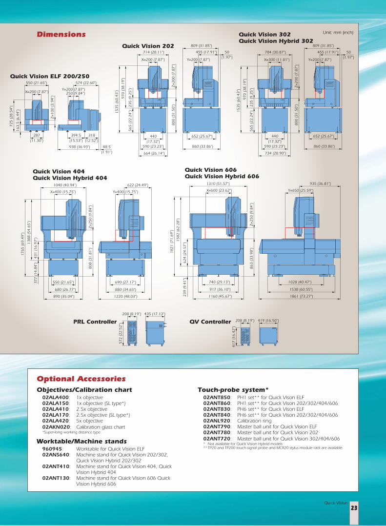
Dimensions
Objectives/Calibration chart02ALA400: 1x objective02ALA150: 1x objective (SL type*)02ALA410: 2.5x objective02ALA170: 2.5x objective (SL type*)02ALA420: 5x objective02AKN020: Calibration glass chart*Super-long working distance type
Worktable/Machine stands960945: Worktable for Quick Vision ELF02ANS640: Machine stand for Quick Vision 202/302,
Quick Vision Hybrid 202/30202ANT410: Machine stand for Quick Vision 404, Quick
Vision Hybrid 40402ANT130: Machine stand for Quick Vision 606 Quick
Vision Hybrid 606
Touch-probe system*02ANT850: PH1 set** for Quick Vison ELF02ANT860: PH1 set** for Quick Vison 202/302/404/60602ANT830: PH6 set** for Quick Vison ELF02ANT840: PH6 set** for Quick Vison 202/302/404/60602ANL920: Calibration ring02ANT790: Master ball unit for Quick Vision ELF02ANT780: Master ball unit for Quick Vision 20202ANT720: Master ball unit for Quick Vision 302/404/606* Not available for Quick Vision Hybrid models** TP20 and TP200 touch-signal probe and MCR20 stylus module rack are available.
Optional Accessories
Specifications are subject to change without notice.
Printed in Japan426.000404 (12) eFP
Mitutoyo Corporation20-1, Sakado 1-Chome, Takatsu-ku, Kawasaki-shi,Kanagawa 213-8533, JapanPhone (044)813-8230 Fax (044)813-8231http://www.mitutoyo.co.jp
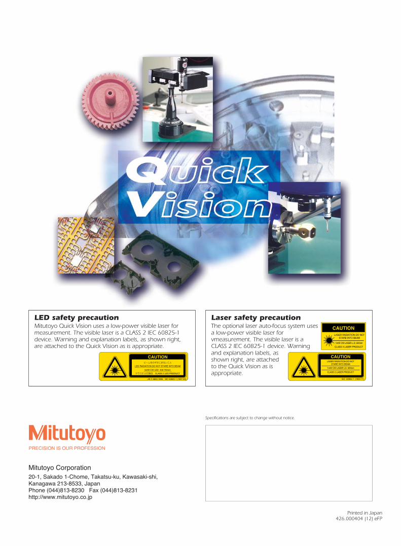
Laser safety precautionThe optional laser auto-focus system usesa low-power visible laser forvmeasurement. The visible laser is aCLASS 2 IEC 60825-1 device. Warningand explanation labels, asshown right, are attachedto the Quick Vision as isappropriate.
LED safety precautionMitutoyo Quick Vision uses a low-power visible laser formeasurement. The visible laser is a CLASS 2 IEC 60825-1device. Warning and explanation labels, as shown right,are attached to the Quick Vision as is appropriate.


