36
CATALOG FIBERGLASS FRAMING SYSTEMS A PART OF
CATALOG
FIBERGLASS FRAMING SYSTEMS
A PART OF
2 Aickinstrut
INTRODUCTION
Aickinstrut Fiberglass Strut is the most widely used and accepted nonmetallic strut support system in the world because it is the most complete quality line of nonmetallic accessories, fasteners, hangers, pipe clamps and channels available. Aickinstrut is a versatile, high-strength product that has been successfully used in thousands of applications world-wide. Some of those applications include: wastewater treatment, refineries, chemical plants, marinas, pulp and paper, desalination facilities, theme parks, aquariums and underground vaults.
Made from entirely nonmetallic, corrosion resistant resins, Aickinstrut can be used in demanding environments where steel strut systems have traditionally failed. Its lightweight components can be installed quickly and easily using standard metal working tools. All Aickinstrut parts incorpo-rate the highest quality materials to provide superior chemical resistance, strength, flame resistance and ultraviolet protection.
Because Aickinstrut manufactures a complete corrosion resistant strut sup-port system, the customer has the benefit of purchasing all of these items from a single source, thereby minimizing start up and delivery delays.
Aickinstrut stands ready to provide assistance through its network of distributors and sales representatives.
3copecabletray.com
Table of Contents
AICKINSTRUT SYSTEMIntroduction ................................................................................................ 2
Technical InformationFabrication ................................................................................................. .4Materials ...................................................................................................... 4Temperature Ranges ................................................................................ 4Typical Properties ................................................................................. 5–6Aickinstrut Specifications ....................................................................... 7Chemical Resistance .............................................................................8-9
Channel FramingChannel Framing .....................................................................................10Concrete Embedment Channel ...........................................................10SST Channel .............................................................................................10Channel Profiles .......................................................................................11Channel Loading .............................................................................. 12–15
Channel Framing AccessoriesChannel Fittings ............................................................................... 16–18Post Bases .................................................................................................19Channel Spacers ......................................................................................19Channel Capping Strip ...........................................................................19Channel End Cap .....................................................................................19
Pipe ClampsAickinclamps Adjustable Pipe Clamps ..............................................20Rigid Pipe Clamps ...................................................................................21Two-Hole Pipe Straps .............................................................................21Channel Caps & Spacers .......................................................................22U-Bolts ........................................................................................................22
FastenersFiberfast Bolts ...........................................................................................23Vinyl Ester Square Head Bolts ............................................................. 23Fiberfast Hex Nuts ...................................................................................24Vinyl Ester Square Nuts .........................................................................24Flat Washers .............................................................................................24Channel Nuts ............................................................................................25Saddle Clips ..............................................................................................25Stop-Lock Assemblies ............................................................................25
Pipe HangersClevis Hangers .........................................................................................26
Pipe Hanging AccessoriesBeam Clamps ...........................................................................................27Beam Clamp Clips ...................................................................................27Threaded Rod ...........................................................................................28Duraclamp C-Clamps ..............................................................................28Channel Hanger .......................................................................................28
Pipe SupportsPower-Racks Stanchions .......................................................................29Wall Bracket ..............................................................................................29
AICKINSTRUT SYSTEM (cont.)
Instrument & Pipe StandsHeavy Duty Post Base ............................................................................30Instrument & Pipe Stands .....................................................................30
AICKINSHAPE
Introduction ................................................................................. 31
Structural ShapesStructural Shapes ............................................................................. 31-33
4 Aickinstrut
AICKINSTRUT FABRICATIONThe installation of fiberglass channel and accessories is similar to the installation of metallic channel and accessories. All standard installation practices and procedures apply. In general, special handling is not required. Fabrication of Aickinstrut components requires just three simple operations; cutting, drilling and sealing as described below.
Cutting – Cutting can be accomplished with a wide variety of saws. Hand held saws, such as hack saws (24 to 32 teeth per inch) are suitable when a few number of cuts are required. For frequent cutting, a circular power saw with a carbide-tipped masonry blade yields the best results and the greatest number of cuts. When using a power saw, dust filter masks, gloves and long sleeve clothing should be worn.
Drilling – Any standard twist bit, even when used with battery-powered drills will work well. Carbide-tipped drill bits are recommended.
LABOR SAVINGSAickinstrut fiberglass structural members can be cut and drilled at a much faster rate than steel. Typically, fiberglass can be fabricated in less than half the time. As a result, substantial labor savings will be realized. Also, Aickinstrut products average 1⁄3 the weight of their steel counterparts, making them much easier to handle on the job site.
RELATIVE MATERIAL COSTSAickinstrut materials are advantageously priced relative to specialty metals traditionally used in corrosive environ-ments. Aickinstrut, even though slightly more expensive than pre-galvanized channel, can be used with the knowledge that it will not have to be maintained regularly or replaced after a brief time. Should pre-galvanized chan-nel have to be replaced once, its cost far outweighs the expense of doing the initial installation with Aickinstrut.
MATERIALThe finished Aickinstrut application will utilize a combination of materials from the following resin families:
Material Code Material E PVC (extruded) P Polyester (pultruded) V Vinyl ester (pultruded) PU Polyurethane (injection molded) PP Polypropylene (injection molded) N Nylon (injection molded)
The ability of each material to handle high and low temperatures, chemical exposures and static loads is covered in each of the following sections. By using
these criteria, you will be able to select the optimal Aickinstrut Channel, Fittings and Accessories for your particular applications.
OPERATING ENVIRONMENTIn order to design an Aickinstrut system for your application, consideration should be given to the maximum operating conditions. These “worst case” conditions will determine which type of Aickinstrut materials are best suited for your application. The three “worst case” operating conditions to consider are:
• Temperature
• Chemical Environment
• Loading
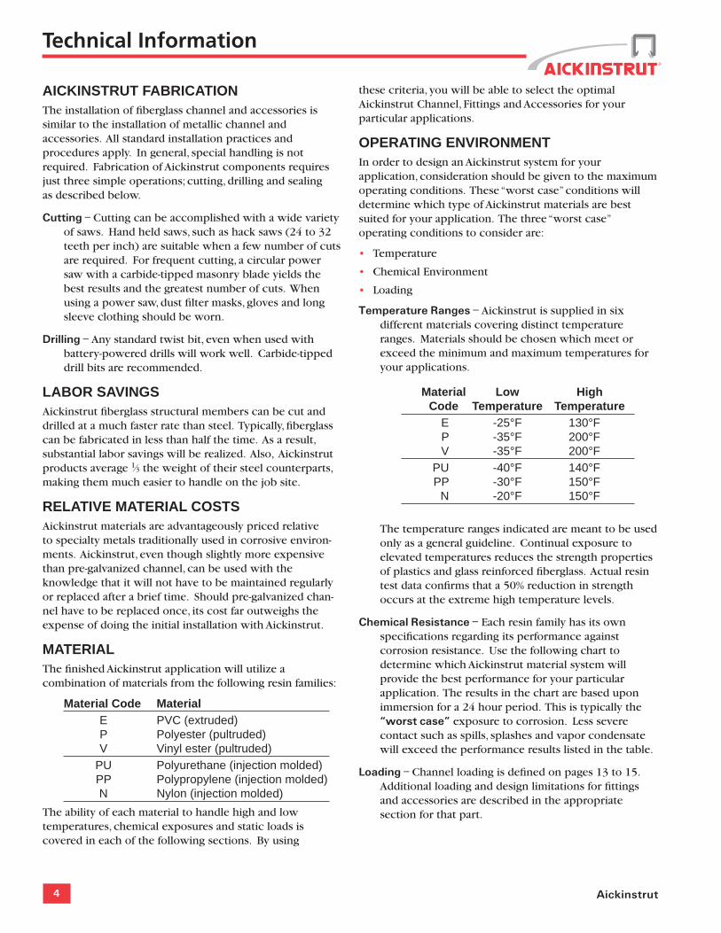
Temperature Ranges – Aickinstrut is supplied in six different materials covering distinct temperature ranges. Materials should be chosen which meet or exceed the minimum and maximum temperatures for your applications.
Material Low High Code Temperature Temperature E -25°F 130°F P -35°F 200°F V -35°F 200°F PU -40°F 140°F PP -30°F 150°F N -20°F 150°F
The temperature ranges indicated are meant to be used only as a general guideline. Continual exposure to elevated temperatures reduces the strength properties of plastics and glass reinforced fiberglass. Actual resin test data confirms that a 50% reduction in strength occurs at the extreme high temperature levels.
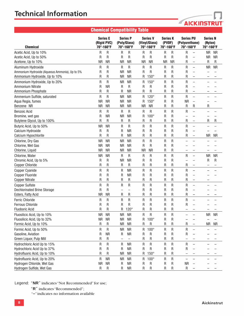
Chemical Resistance – Each resin family has its own specifications regarding its performance against corrosion resistance. Use the following chart to determine which Aickinstrut material system will provide the best performance for your particular application. The results in the chart are based upon immersion for a 24 hour period. This is typically the “worst case” exposure to corrosion. Less severe contact such as spills, splashes and vapor condensate will exceed the performance results listed in the table.
Loading – Channel loading is defined on pages 13 to 15. Additional loading and design limitations for fittings and accessories are described in the appropriate section for that part.
Technical Information
5copecabletray.com
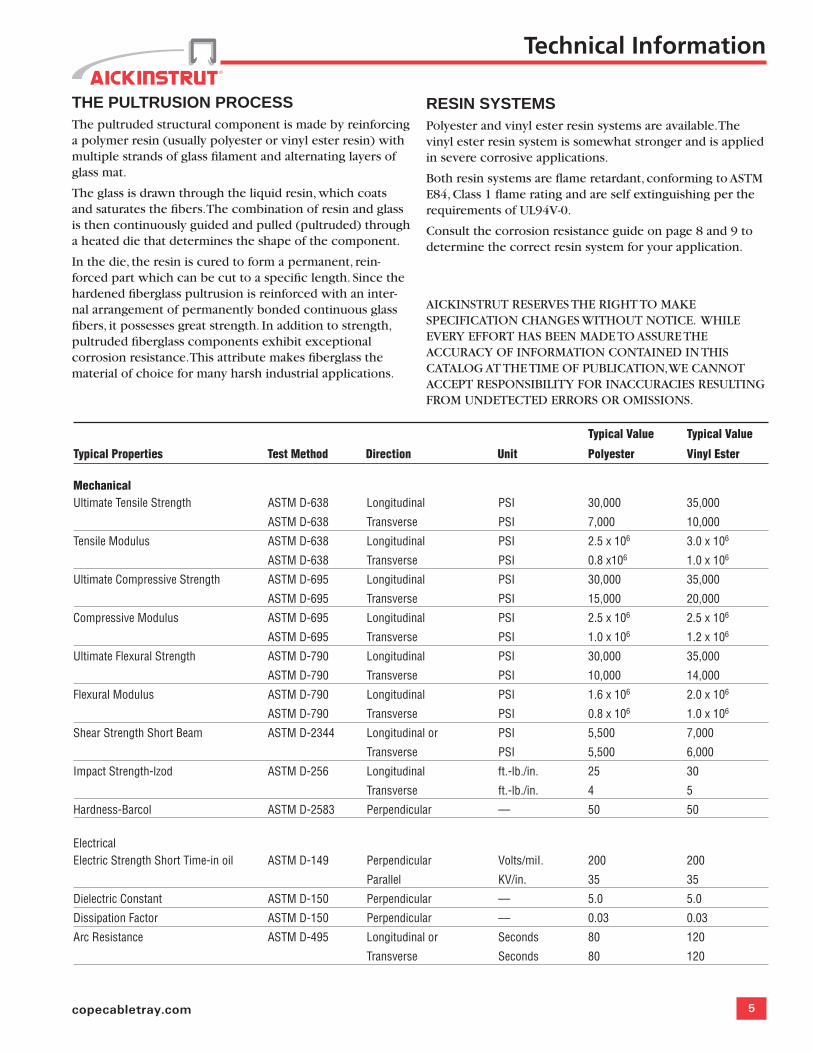
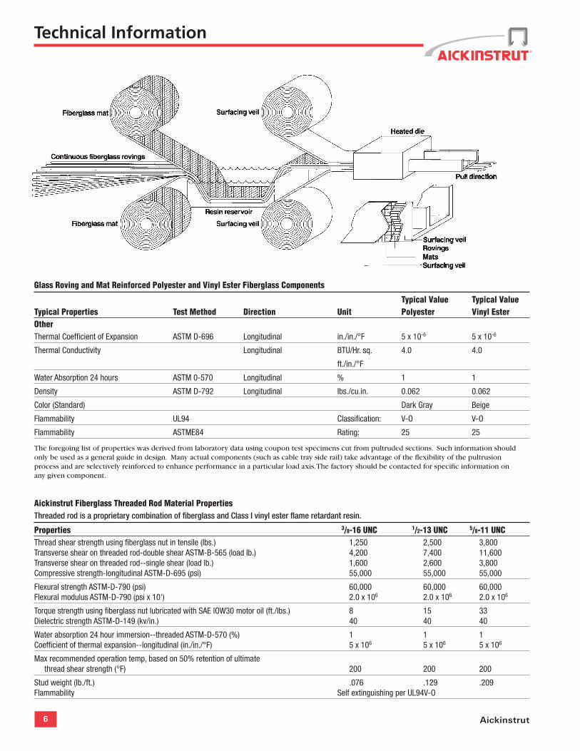
THE PULTRUSION PROCESS The pultruded structural component is made by reinforcing a polymer resin (usually polyester or vinyl ester resin) with multiple strands of glass filament and alternating layers of glass mat.
The glass is drawn through the liquid resin, which coats and saturates the fibers. The combination of resin and glass is then continuously guided and pulled (pultruded) through a heated die that determines the shape of the component.
In the die, the resin is cured to form a permanent, rein-forced part which can be cut to a specific length. Since the hardened fiberglass pultrusion is reinforced with an inter-nal arrangement of permanently bonded continuous glass fibers, it possesses great strength. In addition to strength, pultruded fiberglass components exhibit exceptional corrosion resistance. This attribute makes fiberglass the material of choice for many harsh industrial applications.
RESIN SYSTEMS Polyester and vinyl ester resin systems are available. The vinyl ester resin system is somewhat stronger and is applied in severe corrosive applications.
Both resin systems are flame retardant, conforming to ASTM E84, Class 1 flame rating and are self extinguishing per the requirements of UL94V-0.
Consult the corrosion resistance guide on page 8 and 9 to determine the correct resin system for your application.
AICKINSTRUT RESERVES THE RIGHT TO MAKE SPECIFICATION CHANGES WITHOUT NOTICE. WHILE EVERY EFFORT HAS BEEN MADE TO ASSURE THE ACCURACY OF INFORMATION CONTAINED IN THIS CATALOG AT THE TIME OF PUBLICATION, WE CANNOT ACCEPT RESPONSIBILITY FOR INACCURACIES RESULTING FROM UNDETECTED ERRORS OR OMISSIONS.
Typical Value Typical Value
Typical Properties Test Method Direction Unit Polyester Vinyl Ester MechanicalUltimate Tensile Strength ASTM D-638 Longitudinal PSI 30,000 35,000
ASTM D-638 Transverse PSI 7,000 10,000
Tensile Modulus ASTM D-638 Longitudinal PSI 2.5 x 10⁶ 3.0 x 10⁶
ASTM D-638 Transverse PSI 0.8 x10⁶ 1.0 x 10⁶
Ultimate Compressive Strength ASTM D-695 Longitudinal PSI 30,000 35,000
ASTM D-695 Transverse PSI 15,000 20,000
Compressive Modulus ASTM D-695 Longitudinal PSI 2.5 x 10⁶ 2.5 x 10⁶
ASTM D-695 Transverse PSI 1.0 x 10⁶ 1.2 x 10⁶
Ultimate Flexural Strength ASTM D-790 Longitudinal PSI 30,000 35,000
ASTM D-790 Transverse PSI 10,000 14,000
Flexural Modulus ASTM D-790 Longitudinal PSI 1.6 x 10⁶ 2.0 x 10⁶
ASTM D-790 Transverse PSI 0.8 x 10⁶ 1.0 x 10⁶
Shear Strength Short Beam ASTM D-2344 Longitudinal or PSI 5,500 7,000
Transverse PSI 5,500 6,000
Impact Strength-lzod ASTM D-256 Longitudinal ft.-lb./in. 25 30
Transverse ft.-lb./in. 4 5
Hardness-Barcol ASTM D-2583 Perpendicular –– 50 50
ElectricalElectric Strength Short Time-in oil ASTM D-149 Perpendicular Volts/miI. 200 200
Parallel KV/in. 35 35
Dielectric Constant ASTM D-150 Perpendicular –– 5.0 5.0
Dissipation Factor ASTM D-150 Perpendicular –– 0.03 0.03
Arc Resistance ASTM D-495 Longitudinal or Seconds 80 120
Transverse Seconds 80 120
Technical Information
6 Aickinstrut
Glass Roving and Mat Reinforced Polyester and Vinyl Ester Fiberglass Components
Typical Value Typical ValueTypical Properties Test Method Direction Unit Polyester Vinyl EsterOtherThermal Coefficient of Expansion ASTM D-696 Longitudinal in./in./°F 5 x 10⁻⁶ 5 x 10⁻⁶
Thermal Conductivity Longitudinal BTU/Hr. sq. 4.0 4.0
ft./in./°F
Water Absorption 24 hours ASTM 0-570 Longitudinal % 1 1
Density ASTM D-792 Longitudinal Ibs./cu.in. 0.062 0.062
Color (Standard) Dark Gray Beige
Flammability UL94 Classification: V-O V-O
Flammability ASTME84 Rating: 25 25
The foregoing list of properties was derived from laboratory data using coupon test specimens cut from pultruded sections. Such information should only be used as a general guide in design. Many actual components (such as cable tray side rail) take advantage of the flexibility of the pultrusion process and are selectively reinforced to enhance performance in a particular load axis. The factory should be contacted for specific information on any given component.
Aickinstrut Fiberglass Threaded Rod Material Properties Threaded rod is a proprietary combination of fiberglass and Class I vinyl ester flame retardant resin.
Properties 3/8-16 UNC 1/2-13 UNC 5/8-11 UNCThread shear strength using fiberglass nut in tensile (Ibs.) 1,250 2,500 3,800 Transverse shear on threaded rod-double shear ASTM-B-565 (load lb.) 4,200 7,400 11,600Transverse shear on threaded rod--single shear (load lb.) 1,600 2,600 3,800Compressive strength-longitudinal ASTM-D-695 (psi) 55,000 55,000 55,000
Flexural strength ASTM-D-790 (psi) 60,000 60,000 60,000Flexural modulus ASTM-D-790 (psi x 10') 2.0 x 10⁶ 2.0 x 10⁶ 2.0 x 10⁶
Torque strength using fiberglass nut lubricated with SAE lOW30 motor oil (ft./lbs.) 8 15 33Dielectric strength ASTM-D-149 (kv/in.) 40 40 40
Water absorption 24 hour immersion--threaded ASTM-D-570 (%) 1 1 1Coefficient of thermal expansion--longitudinal (in./in./°F) 5 x 10⁶ 5 x 10⁶ 5 x 10⁶
Max recommended operation temp, based on 50% retention of ultimate thread shear strength (°F) 200 200 200
Stud weight (Ib./ft.) .076 .129 .209Flammability Self extinguishing per UL94V-O
Technical Information
7copecabletray.com
4.4 Channel section lengths shall be supplied in 10' or 20' lengths (±1⁄8").
4.5 Universal Pipe Clamps shall have full interlocking contact with interior channel flanges to maximize pull-out resistance and be adjustable to accommodate a minimum 3⁄4" variance in piping or conduit O.D. sizes.
5.0 STANDARDS
5.1 Glass reinforced and PVC channels covered in this specification shall have a flame spread rating of 25 or less when tested per ASTM E84 and meet the requirements of UL 94V0 thereby qualifying them as Class 1 material in the Uniform Building Code.
5.2 Glass reinforced channels covered in this specification shall comply with the requirements of ASTM D 3917 and ASTM D 4385 which govern the dimensional tolerance and visual defects of pultruded shapes.
6.0 GENERAL
6.1 Aickinstrut Nonmetallic Channel Framing shall be furnished as a system which includes all the necessary fasteners, channel splice plates, brackets, sealants, hangers, pipe clamps, etc.
6.2 Nonmetallic fasteners shall be manufactured from long glass fiber reinforced polyurethane to ensure maximum strength and corrosion resistance.
6.3 All components of the Aickinstrut Channel Framing System shall be nonmetallic except where type 316 stainless steel hardware is used as part of the assembly.
6.4 Aickinstrut is manufactured by Aickinstrut, a subsidiary of T. J. Cope, Philadelphia, Pennsylvania, 1-800-426-4293.
6.5 The manufacturer shall not have had less than 10 years experience in manufacturing strut systems.
6.6 Most products are manufactured in the United States of America. Some items are outsourced where deemed necessary.
Aickinstrut Specifications
1.0 SCOPE
1.1 This specification covers the requirements for the Aickinstrut Nonmetallic Channel Framing System.
2.0 MATERIAL
2.1 FRP channel shall be of pultruded glass reinforced polyester or vinyl ester resin having the physical property values listed in this catalog.
2.2 PVC channel shall be of extruded polyvinyl chloride having the physical property values listed in this catalog.
2.3 Some accessories shall be of injection molded, 40% long glass fiber reinforced polyurethane, polypropylene or nylon.
3.0 COMPOSITION
3.1 Glass reinforced channel shall have a synthetic surfacing veil applied on exterior surfaces to improve weatherability and inhibit ultraviolet degradation.
3.2 PVC channel shall be manufactured from a U.V. stabilized resin and incorporate dark gray pigment to improve weatherability and inhibit ultraviolet degradation.
4.0 STRUCTURAL DESIGN
4.1 Channel shall incorporate Aickinstrut's patented flange profile design which allows full and positive interlocking contact of channel accessories and prohibits premature flange failure from torqued accessories.
4.2 Channel profile dimensions shall be:
15⁄8" x 15⁄8" x 3⁄16", 11⁄2" x 11⁄2" x 3⁄16", or 11⁄2" x 11⁄8" x 3⁄16".
4.3 All 15⁄8" x 15⁄8" channel profiles shall have a minimum pull out resistance of 1,000 pounds when load is applied over a 3⁄8" long section of the inside flanges.
Technical Information
8 Aickinstrut
Chemical Compatibility Table
Series E Series P Series V Series K Series PU Series N (Rigid PVC) (Poly/Glass) (Vinyl/Glass) (PVDF) (Polyurethane) (Nylon) Chemical 70°-160°F 70°-160°F 70°-160°F 70°-160°F 70°-160°F 70°-160°FAcetic Acid, Up to 10% R R R R R R R R R – NR NRAcetic Acid, Up to 50% R R R R R R R R R – NR NRAcetone, Up to 10% NR NR NR NR NR NR NR NR R – R R
Aluminum Hydroxide R R R R R R R R R – NR NRAmmonium Hydroxide (Aqueous Ammonia), Up to 5% R R NR NR R R R R R – – –Ammonium Hydroxide, Up to 10% R R NR NR R 150° R R R – – –
Ammonium Hydroxide, Up to 20% R R NR NR R 150° R R R – – –Ammonium Nitrate R NR R R R R R R R – – –Ammonium Phosphate R R R NR R R R R R – – –
Ammenium Sulfide, saturated R R NR NR R 120° R R R – – –Aqua Regia, fumes NR NR NR NR R 150° R R NR – – –Benzene NR NR NR NR NR NR NR R R R R R
Benzoic Acid R R R R R R R R R – – –Bromine, wet gas R NR NR NR R 100° R R – – – –Butylene Glycol, Up to 100% R R R R R R R R R – R R
Butyric Acid, Up to 50% NR NR R R R R R R R – – –Calcium Hydroxide R R R NR R R R R R – – –Calcium Hypochlorite R R R NR R R R R R – NR NR
Chlorine, Dry Gas NR NR NR NR R R R R – – – –Chlorine, Wet Gas NR NR NR NR R R R R – – – –Chlorine, Liquid NR NR NR NR NR NR R R – – – –
Chlorine, Water NR NR R R R R R R R – NR NRChromic Acid, Up to 5% R R NR NR R R R R – – R RCopper Chloride R R R R R R R R R – – –
Copper Cyanide R R R NR R R R R R – – –Copper Fluoride R R R NR R R R R R – – –Copper Nitrate R R R R R R R R R – –
Copper Sulfate R R R R R R R R R – – –Dechlorinated Brine Storage R R – – R R R R R – – –Esters, Fatty Acid NR NR R R R R R R R – – –
Ferric Chloride R R R R R R R R R – – –Ferrous Chloride R R R R R R R R R – – –Fluoboric Acid R R R 120° R R R R – – – –
Fluosilicic Acid, Up to 10% NR NR NR NR R R R R – – NR NRFluosilicic Acid, Up to 32% NR NR NR NR R 100° R R – – – –Formic Acid, Up to 10% R R NR NR R R R R R – NR NR
Formic Acid, Up to 50% R R NR NR R 100° R R R – – –Gasoline, Aviation R NR R NR R R R R R – – –Green Liquor, Pulp Mill R R – – R R R R – – – –
Hydrochloric Acid Up to 15% R R R NR R R R R R – – –Hydrochloric Acid Up to 37% R R R NR R R R R R – – –Hydrofluoric Acid, Up to 10% R R NR NR R 150° R R – – – –
Hydrofluoric Acid, Up to 20% R NR NR NR R 100° R R – – – –Hydrogen Chloride, Wet Gas NR NR R NR R R R R NR – – –Hydrogen Sulfide, Wet Gas R R R NR R R R R R – – –
Legend: “NR” indicates “Not Recommended” for use;
“R” indicates “Recommended”; “–” indicates no information available
Technical Information
9copecabletray.com
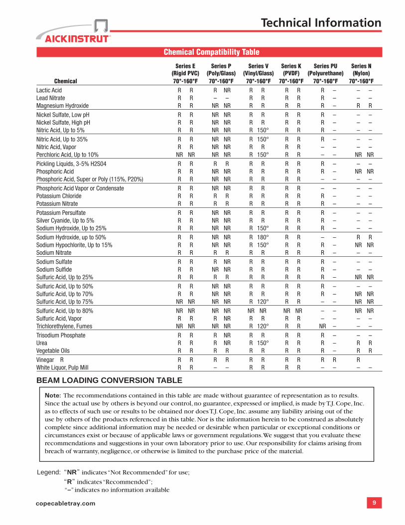
Chemical Compatibility Table
Series E Series P Series V Series K Series PU Series N (Rigid PVC) (Poly/Glass) (Vinyl/Glass) (PVDF) (Polyurethane) (Nylon) Chemical 70°-160°F 70°-160°F 70°-160°F 70°-160°F 70°-160°F 70°-160°FLactic Acid R R R NR R R R R R – – –Lead Nitrate R R – – R R R R R – – –Magnesium Hydroxide R R NR NR R R R R R – R R
Nickel Sulfate, Low pH R R NR NR R R R R R – – –Nickel Sulfate, High pH R R NR NR R R R R R – – –Nitric Acid, Up to 5% R R NR NR R 150° R R R – – –
Nitric Acid, Up to 35% R R NR NR R 150° R R R – – –Nitric Acid, Vapor R R NR NR R R R R – – – –Perchloric Acid, Up to 10% NR NR NR NR R 150° R R – – NR NR
Pickling Liquids, 3-5% H2S04 R R R R R R R R R – – –Phosphoric Acid R R NR NR R R R R R – NR NRPhosphoric Acid, Super or Poly (115%, P20%) R R NR NR R R R R – – – –
Phosphoric Acid Vapor or Condensate R R NR NR R R R R – – – –Potassium Chloride R R R R R R R R R – – –Potassium Nitrate R R R R R R R R R – – –
Potassium Persulfate R R NR NR R R R R R – – –Silver Cyanide, Up to 5% R R NR NR R R R R R – – –Sodium Hydroxide, Up to 25% R R NR NR R 150° R R R – – –
Sodium Hydroxide, up to 50% R R NR NR R 180° R R – – R RSodium Hypochlorite, Up to 15% R R NR NR R 150° R R R – NR NRSodium Nitrate R R R R R R R R R – – –
Sodium Sulfate R R R NR R R R R R – – –Sodium Sulfide R R NR NR R R R R R – – –Sulfuric Acid, Up to 25% R R R R R R R R R – NR NR
Sulfuric Acid, Up to 50% R R NR NR R R R R R – – –Sulfuric Acid, Up to 70% R R NR NR R R R R R – NR NRSulfuric Acid, Up to 75% NR NR NR NR R 120° R R – – NR NR
Sulfuric Acid, Up to 80% NR NR NR NR NR NR NR NR – – NR NRSulfuric Acid, Vapor R R R NR R R R R – – – –Trichlorethylene, Fumes NR NR NR NR R 120° R R NR – – –
Trisodium Phosphate R R R NR R R R R R – – –Urea R R R NR R 150° R R R – R RVegetable Oils R R R R R R R R R – R R
Vinegar R R R R R R R R R R R RWhite Liquor, Pulp Mill R R – – R R R R – – – –
BEAM LOADING CONVERSION TABLE
Note: The recommendations contained in this table are made without guarantee of representation as to results. Since the actual use by others is beyond our control, no guarantee, expressed or implied, is made by T.J. Cope, Inc. as to effects of such use or results to be obtained nor does T.J. Cope, Inc. assume any liability arising out of the use by others of the products referenced in this table. Nor is the information herein to be construed as absolutely complete since additional information may be needed or desirable when particular or exceptional conditions or circumstances exist or because of applicable laws or government regulations. We suggest that you evaluate these recommendations and suggestions in your own laboratory prior to use. Our responsibility for claims arising from breach of warranty, negligence, or otherwise is limited to the purchase price of the material.
Technical Information
Legend: “NR” indicates “Not Recommended” for use;
“R” indicates “Recommended”; “–” indicates no information available
10 Aickinstrut
NOTE: Aickinstrut SST Channel is not compatible with the Aickinstrut pipe clamps, channel nuts, and grooved fittings shown in this catalog. This profile is designed for use with metallic pipe straps and pipe clamps which are also available from Atkore.
AickinstrutFlangeDesign
Channel
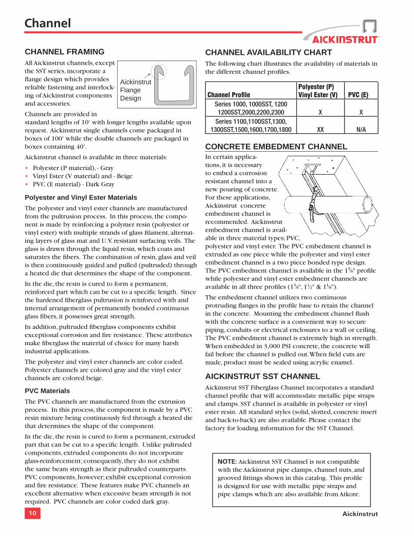
CHANNEL FRAMINGAll Aickinstrut channels, except the SST series, incorporate a flange design which provides reliable fastening and interlock-ing of Aickinstrut components and accessories.
Channels are provided in standard lengths of 10' with longer lengths available upon request. Aickinstrut single channels come packaged in boxes of 100' while the double channels are packaged in boxes containing 40'.
Aickinstrut channel is available in three materials:
• Polyester (P material), - Gray• Vinyl Ester (V material) and - Beige• PVC (E material) - Dark Gray
Polyester and Vinyl Ester Materials
The polyester and vinyl ester channels are manufactured from the pultrusion process. In this process, the compo-nent is made by reinforcing a polymer resin (polyester or vinyl ester) with multiple strands of glass filament, alternat-ing layers of glass mat and U.V. resistant surfacing veils. The glass is drawn through the liquid resin, which coats and saturates the fibers. The combination of resin, glass and veil is then continuously guided and pulled (pultruded) through a heated die that determines the shape of the component.
In the die, the resin is cured to form a permanent, reinforced part which can be cut to a specific length. Since the hardened fiberglass pultrusion is reinforced with and internal arrangement of permanently bonded continuous glass fibers, it possesses great strength.
In addition, pultruded fiberglass components exhibit exceptional corrosion and fire resistance. These attributes make fiberglass the material of choice for many harsh industrial applications.
The polyester and vinyl ester channels are color coded. Polyester channels are colored gray and the vinyl ester channels are colored beige.
PVC Materials
The PVC channels are manufactured from the extrusion process. In this process, the component is made by a PVC resin mixture being continuously fed through a heated die that determines the shape of the component.
In the die, the resin is cured to form a permanent, extruded part that can be cut to a specific length. Unlike pultruded components, extruded components do not incorporate glass-reinforcement; consequently, they do not exhibit the same beam strength as their pultruded counterparts. PVC components, however; exhibit exceptional corrosion and fire resistance. These features make PVC channels an excellent alternative when excessive beam strength is not required. PVC channels are color coded dark gray.
CHANNEL AVAILABILITY CHARTThe following chart illustrates the availability of materials in the different channel profiles.
Channel ProfilePolyester (P) Vinyl Ester (V) PVC (E)
Series 1000, 1000SST, 1200 1200SST,2000,2200,2300 X X
Series 1100,1100SST,1300, 1300SST,1500,1600,1700,1800 XX N/A
CONCRETE EMBEDMENT CHANNELIn certain applica-tions, it is necessary to embed a corrosion resistant channel into a new pouring of concrete. For these applications, Aickinstrut concrete embedment channel is recommended. Aickinstrut embedment channel is avail-able in three material types; PVC, polyester and vinyl ester. The PVC embedment channel is extruded as one piece while the polyester and vinyl ester embedment channel is a two piece bonded type design. The PVC embedment channel is available in the 15⁄8" profile while polyester and vinyl ester embedment channels are available in all three profiles (15⁄8", 11⁄2" & 11⁄8").
The embedment channel utilizes two continuous protruding flanges in the profile base to retain the channel in the concrete. Mounting the embedment channel flush with the concrete surface is a convenient way to secure piping, conduits or electrical enclosures to a wall or ceiling. The PVC embedment channel is extremely high in strength. When embedded in 3,000 PSI concrete, the concrete will fail before the channel is pulled out. When field cuts are made, product must be sealed using acrylic enamel.
AICKINSTRUT SST CHANNELAickinstrut SST Fiberglass Channel incorporates a standard channel profile that will accommodate metallic pipe straps and clamps. SST channel is available in polyester or vinyl ester resin. All standard styles (solid, slotted, concrete insert and back-to-back) are also available. Please contact the factory for loading information for the SST Channel.
11copecabletray.com
15⁄8"15⁄8"
15⁄8" 15⁄8"
1" 15⁄8"
1⁄4"
15⁄8"23⁄8"
15⁄8"31⁄4"
11⁄2"11⁄2"
11⁄2"11⁄2"
1"11⁄2"
1⁄4"23⁄8"11⁄2"
11⁄8"11⁄2"
1"
11⁄2" 11⁄8"
11⁄8"
1⁄4"
11⁄2"23⁄8"
15⁄8" 15⁄8"
1" 15⁄8"
1⁄4"
15⁄8"23⁄8"15⁄8"
15⁄8"15⁄8"
31⁄4"
3"11⁄2"
21⁄4"11⁄2"
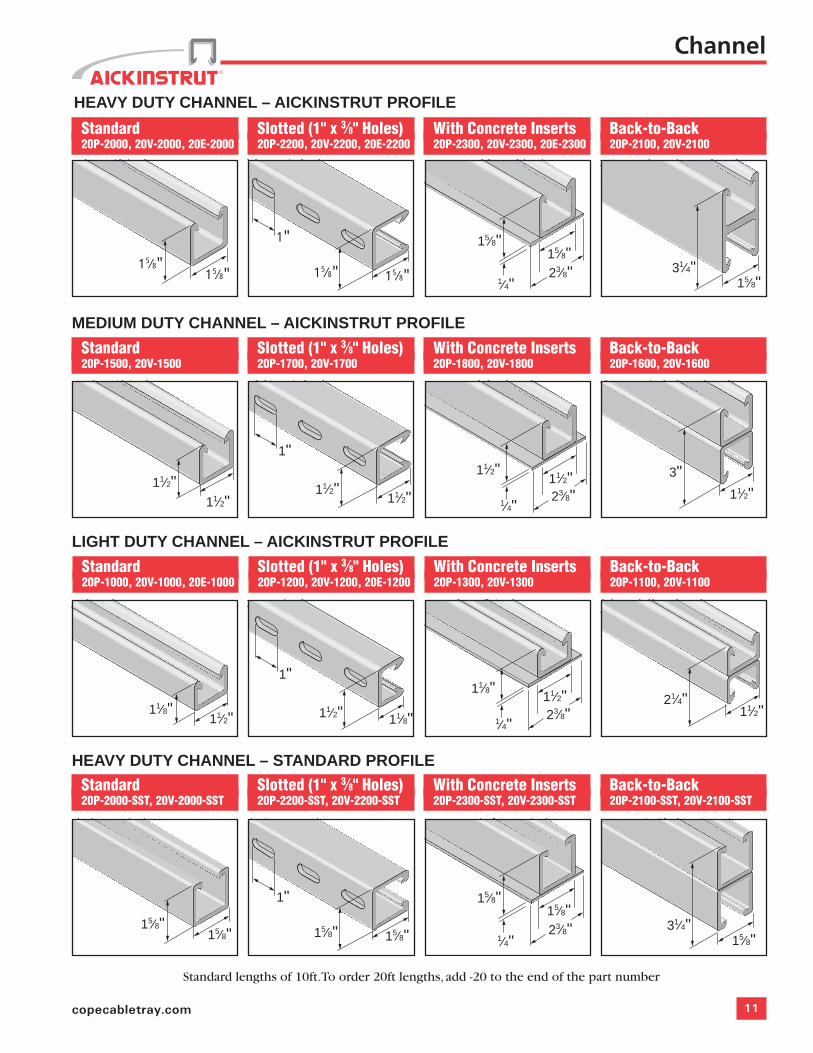
Standard20P-2000, 20V-2000, 20E-2000
Slotted (1" x 3⁄8" Holes)20P-2200, 20V-2200, 20E-2200
With Concrete Inserts20P-2300, 20V-2300, 20E-2300
Back-to-Back20P-2100, 20V-2100
Standard20P-1500, 20V-1500
Slotted (1" x 3⁄8" Holes)20P-1700, 20V-1700
With Concrete Inserts20P-1800, 20V-1800
Back-to-Back20P-1600, 20V-1600
Standard20P-1000, 20V-1000, 20E-1000
Slotted (1" x 3⁄8" Holes)20P-1200, 20V-1200, 20E-1200
With Concrete Inserts20P-1300, 20V-1300
Back-to-Back20P-1100, 20V-1100
Standard20P-2000-SST, 20V-2000-SST
Slotted (1" x 3⁄8" Holes)20P-2200-SST, 20V-2200-SST
With Concrete Inserts20P-2300-SST, 20V-2300-SST
Back-to-Back20P-2100-SST, 20V-2100-SST
HEAVY DUTY CHANNEL – AICKINSTRUT PROFILE
MEDIUM DUTY CHANNEL – AICKINSTRUT PROFILE
LIGHT DUTY CHANNEL – AICKINSTRUT PROFILE
HEAVY DUTY CHANNEL – STANDARD PROFILE
Channel
Standard lengths of 10ft. To order 20ft lengths, add -20 to the end of the part number
15⁄8"15⁄8"
15⁄8" 15⁄8"
1" 15⁄8"
1⁄4"
15⁄8"23⁄8"
15⁄8"31⁄4"
11⁄2"11⁄2"
11⁄2"11⁄2"
1"11⁄2"
1⁄4"23⁄8"11⁄2"
11⁄8"11⁄2"
1"
11⁄2" 11⁄8"
11⁄8"
1⁄4"
11⁄2"23⁄8"
15⁄8" 15⁄8"
1" 15⁄8"
1⁄4"
15⁄8"23⁄8"15⁄8"
15⁄8"15⁄8"
31⁄4"
3"11⁄2"
21⁄4"11⁄2"
15⁄8"15⁄8"
15⁄8" 15⁄8"
1" 15⁄8"
1⁄4"
15⁄8"23⁄8"
15⁄8"31⁄4"
11⁄2"11⁄2"
11⁄2"11⁄2"
1"11⁄2"
1⁄4"23⁄8"11⁄2"
11⁄8"11⁄2"
1"
11⁄2" 11⁄8"
11⁄8"
1⁄4"
11⁄2"23⁄8"
15⁄8" 15⁄8"
1" 15⁄8"
1⁄4"
15⁄8"23⁄8"15⁄8"
15⁄8"15⁄8"
31⁄4"
3"11⁄2"
21⁄4"11⁄2"
15⁄8"15⁄8"
15⁄8" 15⁄8"
1" 15⁄8"
1⁄4"
15⁄8"23⁄8"
15⁄8"31⁄4"
11⁄2"11⁄2"
11⁄2"11⁄2"
1"11⁄2"
1⁄4"23⁄8"11⁄2"
11⁄8"11⁄2"
1"
11⁄2" 11⁄8"
11⁄8"
1⁄4"
11⁄2"23⁄8"
15⁄8" 15⁄8"
1" 15⁄8"
1⁄4"
15⁄8"23⁄8"15⁄8"
15⁄8"15⁄8"
31⁄4"
3"11⁄2"
21⁄4"11⁄2"
12 Aickinstrut
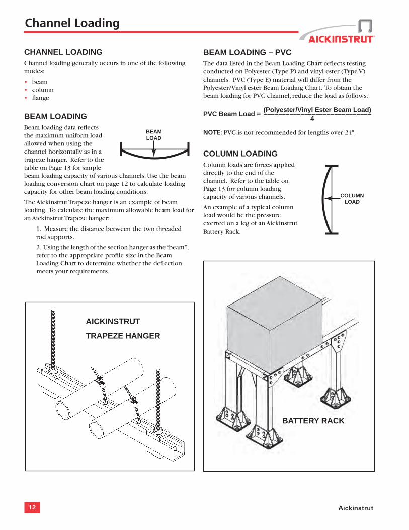
BEAMLOAD
COLUMNLOAD
AICKINSTRUT
TRAPEZE HANGER
BATTERY RACK
CHANNEL LOADINGChannel loading generally occurs in one of the following modes:
• beam• column• flange
BEAM LOADING Beam loading data reflects the maximum uniform load allowed when using the channel horizontally as in a trapeze hanger. Refer to the table on Page 13 for simple beam loading capacity of various channels. Use the beam loading conversion chart on page 12 to calculate loading capacity for other beam loading conditions.
The Aickinstrut Trapeze hanger is an example of beam loading. To calculate the maximum allowable beam load for an Aickinstrut Trapeze hanger:
1. Measure the distance between the two threaded rod supports.
2. Using the length of the section hanger as the “beam”, refer to the appropriate profile size in the Beam Loading Chart to determine whether the deflection meets your requirements.
BEAM LOADING – PVCThe data listed in the Beam Loading Chart reflects testing conducted on Polyester (Type P) and vinyl ester (Type V) channels. PVC (Type E) material will differ from the Polyester/Vinyl ester Beam Loading Chart. To obtain the beam loading for PVC channel, reduce the load as follows:
(Polyester/Vinyl Ester Beam Load) PVC Beam Load = –––––––––––––––––––––––––––––
4
NOTE: PVC is not recommended for lengths over 24".
COLUMN LOADINGColumn loads are forces applied directly to the end of the channel. Refer to the table on Page 13 for column loading capacity of various channels.
An example of a typical column load would be the pressure exerted on a leg of an Aickinstrut Battery Rack.
Channel Loading
13copecabletray.com
FLANGELOAD
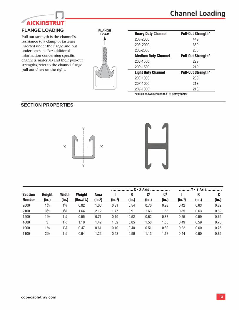
FLANGE LOADINGPull-out strength is the channel's resistance to a clamp or fastener inserted under the flange and put under tension. For additional information concerning specific channels, materials and their pull-out strengths, refer to the channel flange pull-out chart on the right.
Channel Loading
Heavy Duty Channel Pull-Out Strength*20V-2000 44920P-2000 36020E-2000 260 Medium Duty Channel Pull-Out Strength*20V-1500 22920P-1500 219 Light Duty Channel Pull-Out Strength*20E-1000 23920P-1000 21320V-1000 213 *Values shown represent a 3:1 safety factor
.................X - X Axis ............... .........Y - Y Axis............Section Height Width Weight Area I R C1 C2 I R C Number (in.) (in.) (lbs./ft.) (in.2) (in.4) (in.) (in.) (in.) (in.4) (in.) (in.)2000 15⁄8 15⁄8 0.82 1.06 0.31 0.54 0.70 0.93 0.42 0.63 0.82
2100 31⁄2 15⁄8 1.64 2.12 1.77 0.91 1.63 1.63 0.85 0.63 0.82
1500 11⁄2 11⁄2 0.55 0.71 0.19 0.52 0.62 0.88 0.25 0.59 0.75
1600 3 11⁄2 1.10 1.42 1.02 0.85 1.50 1.50 0.49 0.59 0.75
1000 11⁄8 11⁄2 0.47 0.61 0.10 0.40 0.51 0.62 0.22 0.60 0.75
1100 21⁄2 11⁄2 0.94 1.22 0.42 0.59 1.13 1.13 0.44 0.60 0.75
SECTION PROPERTIES
XX
Y
Y
14 Aickinstrut
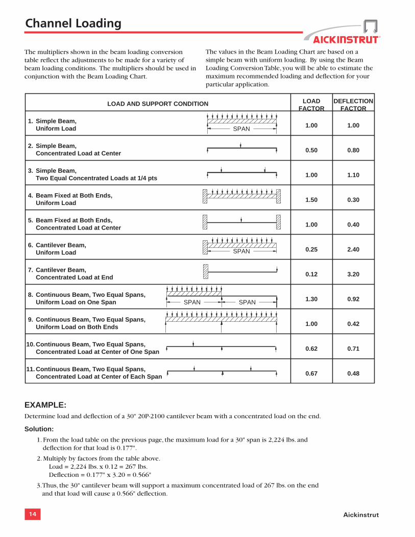
The multipliers shown in the beam loading conversion table reflect the adjustments to be made for a variety of beam loading conditions. The multipliers should be used in conjunction with the Beam Loading Chart.
Continuous Beam, Two Equal Spans,Concentrated Load at Center of Each Span 0.67 0.48
DEFLECTION FACTOR
LOADFACTOR
LOAD AND SUPPORT CONDITION
SPAN
SPAN
1.00
1.00
0.50
0.25
1.50
1.00
1.00
0.12
1.30
0.62
1.10
1.00
0.80
2.40
0.30
0.40
0.42
3.20
0.92
0.71
1. Simple Beam,Uniform Load
2. Simple Beam,Concentrated Load at Center
3. Simple Beam,Two Equal Concentrated Loads at 1/4 pts
4. Beam Fixed at Both Ends,Uniform Load
5. Beam Fixed at Both Ends,Concentrated Load at Center
6. Cantilever Beam,Uniform Load
7. Cantilever Beam,Concentrated Load at End
8. Continuous Beam, Two Equal Spans,Uniform Load on One Span
9. Continuous Beam, Two Equal Spans,Uniform Load on Both Ends
10. Continuous Beam, Two Equal Spans,Concentrated Load at Center of One Span
11.
SPAN SPAN
EXAMPLE: Determine load and deflection of a 30" 20P-2100 cantilever beam with a concentrated load on the end.
Solution:
1. From the load table on the previous page, the maximum load for a 30" span is 2,224 lbs. and deflection for that load is 0.177".
2. Multiply by factors from the table above. Load = 2,224 lbs. x 0.12 = 267 lbs. Deflection = 0.177" x 3.20 = 0.566"
3. Thus, the 30" cantilever beam will support a maximum concentrated load of 267 lbs. on the end and that load will cause a 0.566" deflection.
Channel Loading
The values in the Beam Loading Chart are based on a simple beam with uniform loading. By using the Beam Loading Conversion Table, you will be able to estimate the maximum recommended loading and deflection for your particular application.
15copecabletray.com
Channel Loading
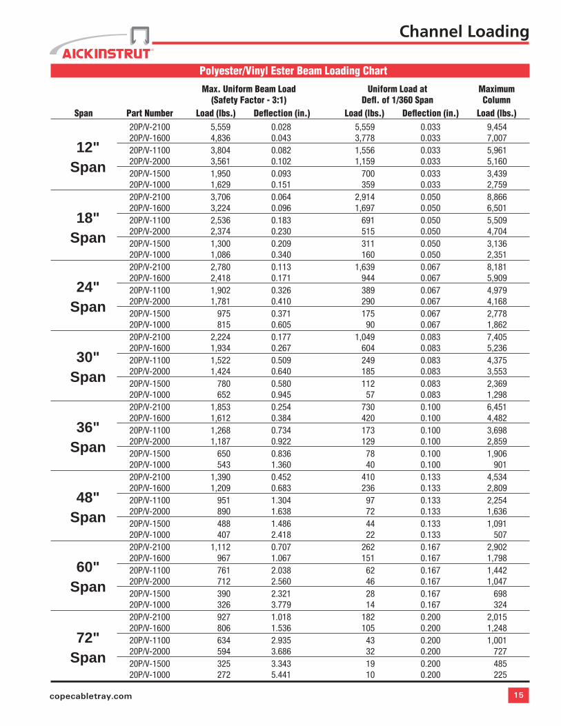
Polyester/Vinyl Ester Beam Loading Chart
Max. Uniform Beam Load Uniform Load at Maximum (Safety Factor - 3:1) Defl. of 1/360 Span Column Span Part Number Load (lbs.) Deflection (in.) Load (lbs.) Deflection (in.) Load (lbs.) 20P/V-2100 5,559 0.028 5,559 0.033 9,454 20P/V-1600 4,836 0.043 3,778 0.033 7,007 20P/V-1100 3,804 0.082 1,556 0.033 5,961 20P/V-2000 3,561 0.102 1,159 0.033 5,160 20P/V-1500 1,950 0.093 700 0.033 3,439 20P/V-1000 1,629 0.151 359 0.033 2,759 20P/V-2100 3,706 0.064 2,914 0.050 8,866 20P/V-1600 3,224 0.096 1,697 0.050 6,501 20P/V-1100 2,536 0.183 691 0.050 5,509 20P/V-2000 2,374 0.230 515 0.050 4,704 20P/V-1500 1,300 0.209 311 0.050 3,136 20P/V-1000 1,086 0.340 160 0.050 2,351 20P/V-2100 2,780 0.113 1,639 0.067 8,181 20P/V-1600 2,418 0.171 944 0.067 5,909 20P/V-1100 1,902 0.326 389 0.067 4,979 20P/V-2000 1,781 0.410 290 0.067 4,168 20P/V-1500 975 0.371 175 0.067 2,778 20P/V-1000 815 0.605 90 0.067 1,862 20P/V-2100 2,224 0.177 1,049 0.083 7,405 20P/V-1600 1,934 0.267 604 0.083 5,236 20P/V-1100 1,522 0.509 249 0.083 4,375 20P/V-2000 1,424 0.640 185 0.083 3,553 20P/V-1500 780 0.580 112 0.083 2,369 20P/V-1000 652 0.945 57 0.083 1,298 20P/V-2100 1,853 0.254 730 0.100 6,451 20P/V-1600 1,612 0.384 420 0.100 4,482 20P/V-1100 1,268 0.734 173 0.100 3,698 20P/V-2000 1,187 0.922 129 0.100 2,859 20P/V-1500 650 0.836 78 0.100 1,906 20P/V-1000 543 1.360 40 0.100 901 20P/V-2100 1,390 0.452 410 0.133 4,534 20P/V-1600 1,209 0.683 236 0.133 2,809 20P/V-1100 951 1.304 97 0.133 2,254 20P/V-2000 890 1.638 72 0.133 1,636 20P/V-1500 488 1.486 44 0.133 1,091 20P/V-1000 407 2.418 22 0.133 507 20P/V-2100 1,112 0.707 262 0.167 2,902 20P/V-1600 967 1.067 151 0.167 1,798 20P/V-1100 761 2.038 62 0.167 1,442 20P/V-2000 712 2.560 46 0.167 1,047 20P/V-1500 390 2.321 28 0.167 698 20P/V-1000 326 3.779 14 0.167 324 20P/V-2100 927 1.018 182 0.200 2,015 20P/V-1600 806 1.536 105 0.200 1,248 20P/V-1100 634 2.935 43 0.200 1,001 20P/V-2000 594 3.686 32 0.200 727 20P/V-1500 325 3.343 19 0.200 485 20P/V-1000 272 5.441 10 0.200 225
12"Span
18"Span
24"Span
30"Span
36"Span
48"Span
60"Span
72"Span
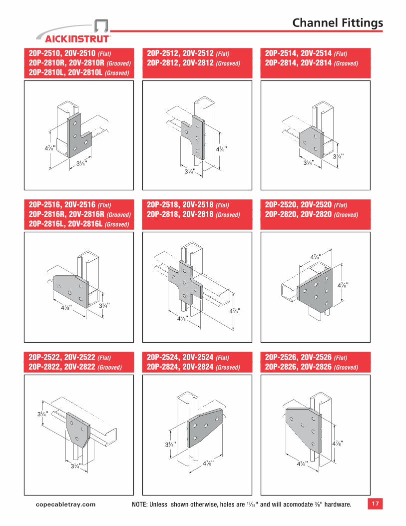
16 AickinstrutNOTE: Unless shown otherwise, holes are 13⁄32" and will acomodate 3⁄8" hardware.
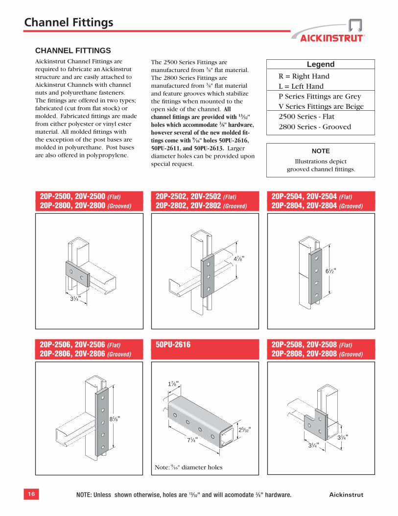
CHANNEL FITTINGSAickinstrut Channel Fittings are required to fabricate an Aickinstrut structure and are easily attached to Aickinstrut Channels with channel nuts and polyurethane fasteners. The fittings are offered in two types; fabricated (cut from flat stock) or molded. Fabricated fittings are made from either polyester or vinyl ester material. All molded fittings with the exception of the post bases are molded in polyurethane. Post bases are also offered in polypropylene.
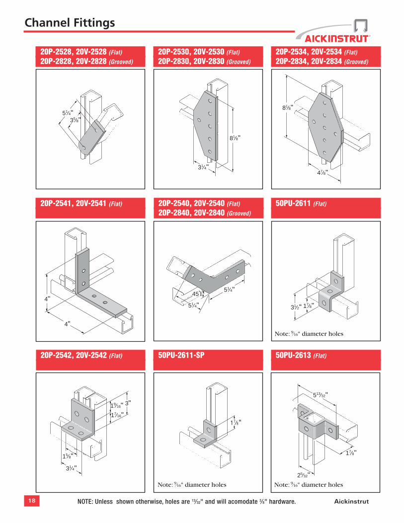
The 2500 Series Fittings are manufactured from 3⁄8" flat material. The 2800 Series Fittings are manufactured from 3⁄8" flat material and feature grooves which stabilize the fittings when mounted to the open side of the channel. All channel fittings are provided with 13⁄32" holes which accommodate 3⁄8" hardware, however several of the new molded fit-tings come with 9⁄16" holes 50PU-2616, 50PU-2611, and 50PU-2613. Larger diameter holes can be provided upon special request.
Legend
R = Right Hand L = Left Hand P Series Fittings are Grey V Series Fittings are Beige 2500 Series - Flat 2800 Series - Grooved
NOTE
Illustrations depict grooved channel fittings.
20P-2500, 20V-2500 (Flat)
20P-2800, 20V-2800 (Grooved)
20P-2506, 20V-2506 (Flat)
20P-2806, 20V-2806 (Grooved)
20P-2502, 20V-2502 (Flat)
20P-2802, 20V-2802 (Grooved)
20P-2504, 20V-2504 (Flat)
20P-2804, 20V-2804 (Grooved)
50PU-2616
20P-2508, 20V-2508 (Flat)
20P-2808, 20V-2808 (Grooved)
31⁄4"
47⁄8"
61⁄2"
81⁄8"
17⁄8"
71⁄4"25⁄32"
31⁄4"31⁄4"
Channel Fittings
Note: 9⁄16" diameter holes
17copecabletray.com NOTE: Unless shown otherwise, holes are 13⁄32" and will acomodate 3⁄8" hardware.
20P-2510, 20V-2510 (Flat)
20P-2810R, 20V-2810R (Grooved)
20P-2810L, 20V-2810L (Grooved)
20P-2516, 20V-2516 (Flat)
20P-2816R, 20V-2816R (Grooved)
20P-2816L, 20V-2816L (Grooved)
20P-2512, 20V-2512 (Flat)
20P-2812, 20V-2812 (Grooved)
20P-2514, 20V-2514 (Flat)
20P-2814, 20V-2814 (Grooved)
20P-2518, 20V-2518 (Flat)
20P-2818, 20V-2818 (Grooved)
20P-2520, 20V-2520 (Flat)
20P-2820, 20V-2820 (Grooved)
20P-2522, 20V-2522 (Flat)
20P-2822, 20V-2822 (Grooved)
20P-2524, 20V-2524 (Flat)
20P-2824, 20V-2824 (Grooved)
20P-2526, 20V-2526 (Flat)
20P-2826, 20V-2826 (Grooved)
47⁄8"
31⁄4"
47⁄8"
31⁄4"
31⁄4"31⁄4"
31⁄4"47⁄8"47⁄8"
47⁄8"
47⁄8"
47⁄8"
31⁄4"
31⁄4"
31⁄4"
47⁄8"
47⁄8"
47⁄8"
Channel Fittings
18 AickinstrutNOTE: Unless shown otherwise, holes are 13⁄32" and will acomodate 3⁄8" hardware.
20P-2528, 20V-2528 (Flat)
20P-2828, 20V-2828 (Grooved)
20P-2530, 20V-2530 (Flat)
20P-2830, 20V-2830 (Grooved)
20P-2534, 20V-2534 (Flat)
20P-2834, 20V-2834 (Grooved)
20P-2541, 20V-2541 (Flat)
20P-2540, 20V-2540 (Flat)
20P-2840, 20V-2840 (Grooved)
50PU-2611 (Flat)
50PU-2613 (Flat)
51⁄4"35⁄8"
81⁄8"
31⁄4"
81⁄8"
47⁄8"
17⁄8"31⁄2"
17⁄8"
513⁄32"
25⁄32"
Channel Fittings
51⁄4"
51⁄4"
45ϒ4"
4"
Note: 9⁄16" diameter holes
Note: 9⁄16" diameter holes
50PU-2611-SP
20P-2542, 20V-2542 (Flat)
17⁄8"
Note: 9⁄16" diameter holes
17⁄16"19⁄16" 3"
31⁄4"
15⁄8"
19copecabletray.com NOTE: Unless shown otherwise, holes are 13⁄32" and will acomodate 3⁄8" hardware.
50PU-2045 (15⁄8")
20PU-5853 (15⁄8"), 20PU-5854 (11⁄2"), 20PU-5855 (11⁄8"), 20PP-5853 (15⁄8"), 20PP-5854 (11⁄2"), 20PP-5855 (11⁄8")
50PU-26361
50PU-2090 (15⁄8")
20PU-5903 (31⁄4"), 20PU-5904 (3"), 20PU-5905 (21⁄4"), 20PP-5903 (31⁄4"), 20PP-5904 (3"), 20PP-5905 (21⁄4")
41⁄2"
51⁄2"
4"
15⁄8"
47⁄8"
47⁄8"
3"
0.4" Dia.
5" 5"
0.4"
3"
5"6 5⁄8"
0.4" Dia.
0.4"
50PU-1508 (11⁄2")50PU-2008 (15⁄8")
47⁄8"
47⁄8"
Channel Fittings
50PU-2538 (Flat)
4"
5" 15⁄8"
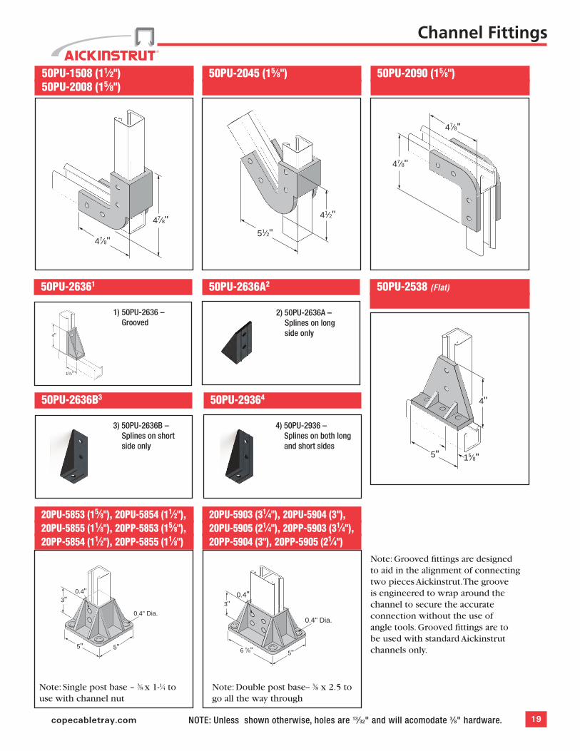
1) 50PU-2636 – Grooved
Note: Grooved fittings are designed to aid in the alignment of connecting two pieces Aickinstrut. The groove is engineered to wrap around the channel to secure the accurate connection without the use of angle tools. Grooved fittings are to be used with standard Aickinstrut channels only.
Note: Double post base-- 3⁄8 x 2.5 to go all the way through
Note: Single post base – 3⁄8 x 1-1⁄4 to use with channel nut
50PU-2636A2
50PU-2636B3 50PU-29364
2) 50PU-2636A – Splines on long side only
3) 50PU-2636B – Splines on short side only
4) 50PU-2936 – Splines on both long and short sides
20 Aickinstrut
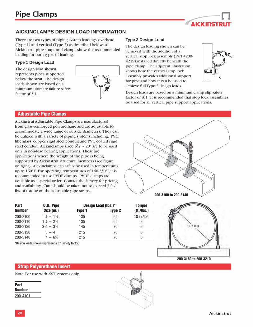
Adjustable Pipe ClampsAickinstrut Adjustable Pipe Clamps are manufactured from glass-reinforced polyurethane and are adjustable to accommodate a wide range of outside diameters. They can be utilized with a variety of piping systems including: PVC, fiberglass, copper, rigid steel conduit and PVC coated rigid steel conduit. Aickinclamps sized 61⁄2" – 20" are to be used only in non-load bearing applications. These are applications where the weight of the pipe is being supported by Aickinstrut structural members (see figure on right). Aickinclamps can safely be used in temperatures up to 160°F. For operating temperatures of 160-230°F, it is recommended to use PVDF clamps. PVDF clamps are available as a special order. Contact the factory for pricing and availability. Care should be taken not to exceed 3 ft./lbs. of torque on the adjustable pipe straps.
Part O.D. Pipe Design Load (lbs.)* TorqueNumber Size (in.) Type 1 Type 2 (ft./lbs.)200-3100 1⁄2 – 11⁄2 135 65 10 in./lbs.200-3110 11⁄2 – 21⁄4 135 65 3200-3120 21⁄4 – 31⁄4 145 70 3200-3130 3 – 4 215 70 3200-3140 4 – 61⁄2 215 70 3*Design loads shown represent a 3:1 safety factor.
AICKINCLAMPS DESIGN LOAD INFORMATION
Type 2 Design Load
The design loading shown can be achieved with the addition of a vertical stop lock assembly (Part #200-4219) installed directly beneath the pipe clamp. The adjacent illustration shows how the vertical stop lock assembly provides additional support for pipe and how it can be used to achieve full Type 2 design loads.
Design loads are based on a minimum clamp slip safety factor or 3:1. It is recommended that stop lock assemblies be used for all vertical pipe support applications.
There are two types of piping system loadings, overhead (Type 1) and vertical (Type 2) as described below. All Aickinstrut pipe straps and clamps show the recommended loading for both types of loading.
Type 1 Design Load
The design load shown represents pipes supported below the strut. The design loads shown are based on a minimum ultimate failure safety factor of 3:1.
Pipe Clamps
200-3100 to 200-3140
200-3150 to 200-3210
Strap Polyurethane InsertNote: For use with -SST systems only
PartNumber200-4101
21copecabletray.com
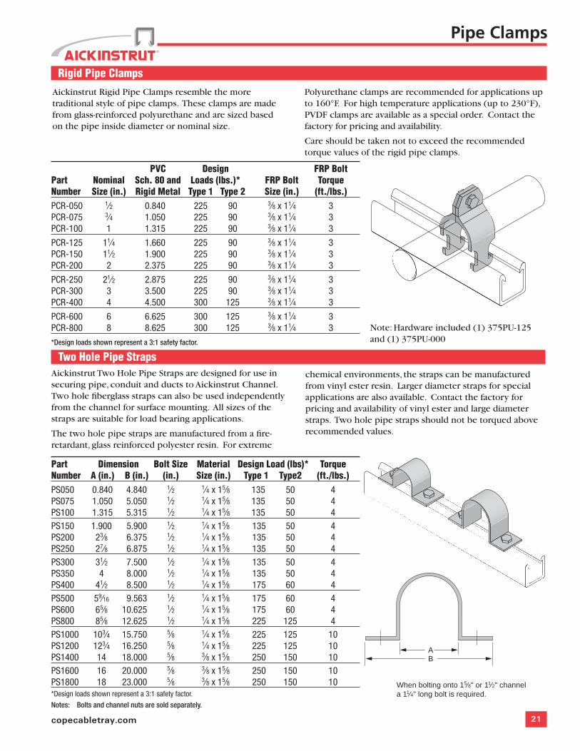
Rigid Pipe Clamps
PVC Design FRP BoltPart Nominal Sch. 80 and Loads (lbs.)* FRP Bolt Torque Number Size (in.) Rigid Metal Type 1 Type 2 Size (in.) (ft./lbs.)PCR-050 1⁄2 0.840 225 90 3⁄8 x 11⁄4 3PCR-075 3⁄4 1.050 225 90 3⁄8 x 11⁄4 3PCR-100 1 1.315 225 90 3⁄8 x 11⁄4 3
PCR-125 11⁄4 1.660 225 90 3⁄8 x 11⁄4 3PCR-150 11⁄2 1.900 225 90 3⁄8 x 11⁄4 3PCR-200 2 2.375 225 90 3⁄8 x 11⁄4 3
PCR-250 21⁄2 2.875 225 90 3⁄8 x 11⁄4 3PCR-300 3 3.500 225 90 3⁄8 x 11⁄4 3PCR-400 4 4.500 300 125 3⁄8 x 11⁄4 3
PCR-600 6 6.625 300 125 3⁄8 x 11⁄4 3PCR-800 8 8.625 300 125 3⁄8 x 11⁄4 3
*Design loads shown represent a 3:1 safety factor.
Pipe Clamps
Two Hole Pipe StrapsAickinstrut Two Hole Pipe Straps are designed for use in securing pipe, conduit and ducts to Aickinstrut Channel. Two hole fiberglass straps can also be used independently from the channel for surface mounting. All sizes of the straps are suitable for load bearing applications.
The two hole pipe straps are manufactured from a fire-retardant, glass reinforced polyester resin. For extreme
Part Dimension Bolt Size Material Design Load (lbs)* TorqueNumber A (in.) B (in.) (in.) Size (in.) Type 1 Type2 (ft./lbs.)PS050 0.840 4.840 1⁄2 1⁄4 x 15⁄8 135 50 4PS075 1.050 5.050 1⁄2 1⁄4 x 15⁄8 135 50 4PS100 1.315 5.315 1⁄2 1⁄4 x 15⁄8 135 50 4PS150 1.900 5.900 1⁄2 1⁄4 x 15⁄8 135 50 4PS200 23⁄8 6.375 1⁄2 1⁄4 x 15⁄8 135 50 4PS250 27⁄8 6.875 1⁄2 1⁄4 x 15⁄8 135 50 4PS300 31⁄2 7.500 1⁄2 1⁄4 x 15⁄8 135 50 4PS350 4 8.000 1⁄2 1⁄4 x 15⁄8 135 50 4PS400 41⁄2 8.500 1⁄2 1⁄4 x 15⁄8 175 60 4PS500 59⁄16 9.563 1⁄2 1⁄4 x 15⁄8 175 60 4PS600 65⁄8 10.625 1⁄2 1⁄4 x 15⁄8 175 60 4PS800 85⁄8 12.625 1⁄2 1⁄4 x 15⁄8 225 125 4PS1000 103⁄4 15.750 5⁄8 1⁄4 x 15⁄8 225 125 10PS1200 123⁄4 16.250 5⁄8 1⁄4 x 15⁄8 225 125 10PS1400 14 18.000 5⁄8 3⁄8 x 15⁄8 250 150 10PS1600 16 20.000 5⁄8 3⁄8 x 15⁄8 250 150 10PS1800 18 23.000 5⁄8 3⁄8 x 15⁄8 250 150 10*Design loads shown represent a 3:1 safety factor.
Notes: Bolts and channel nuts are sold separately.
Aickinstrut Rigid Pipe Clamps resemble the more traditional style of pipe clamps. These clamps are made from glass-reinforced polyurethane and are sized based on the pipe inside diameter or nominal size.
Polyurethane clamps are recommended for applications up to 160°F. For high temperature applications (up to 230°F), PVDF clamps are available as a special order. Contact the factory for pricing and availability.
Care should be taken not to exceed the recommended torque values of the rigid pipe clamps.
chemical environments, the straps can be manufactured from vinyl ester resin. Larger diameter straps for special applications are also available. Contact the factory for pricing and availability of vinyl ester and large diameter straps. Two hole pipe straps should not be torqued above recommended values.
When bolting onto 15⁄8" or 11⁄2" channel a 11⁄4" long bolt is required.
AB
Note: Hardware included (1) 375PU-125 and (1) 375PU-000
22 Aickinstrut
Channel End Cap AIC-EC
The Aickin-End Cap is made from red PVC and designed for 15⁄8" channel. End caps are desired when the ends of the channel need to be enclosed. The Aickin-End Cap easily installs by pressing it onto the end of the channel opening.
Channel spacers are designed to prevent wall compression under heavy loading conditions. Such loading occurs during the torquing of hardware for channel fittings. The spacers are molded from polyurethane and will accommodate 3⁄8" and 1⁄2" bolts. The spacers are designed to be used only with 15⁄8" and 11⁄2" channels.
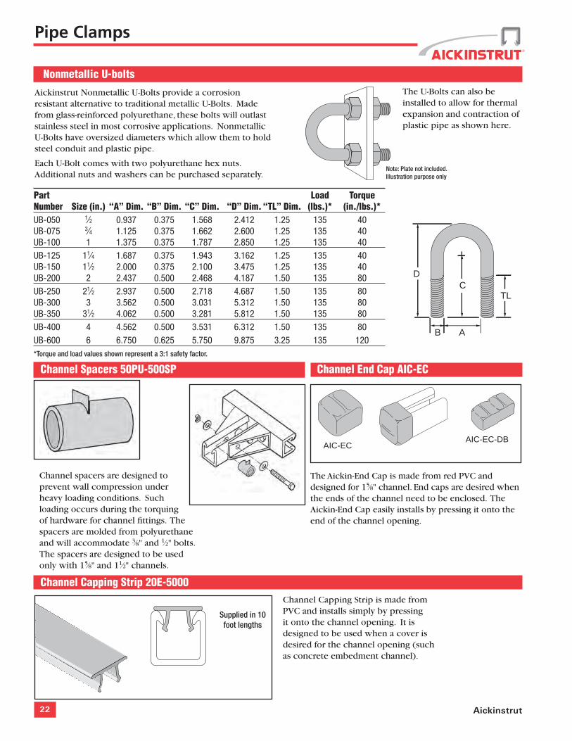
Nonmetallic U-bolts
Part Load TorqueNumber Size (in.) “A” Dim. “B” Dim. “C” Dim. “D” Dim. “TL” Dim. (lbs.)* (in./lbs.)*UB-050 1⁄2 0.937 0.375 1.568 2.412 1.25 135 40UB-075 3⁄4 1.125 0.375 1.662 2.600 1.25 135 40UB-100 1 1.375 0.375 1.787 2.850 1.25 135 40UB-125 11⁄4 1.687 0.375 1.943 3.162 1.25 135 40UB-150 11⁄2 2.000 0.375 2.100 3.475 1.25 135 40UB-200 2 2.437 0.500 2.468 4.187 1.50 135 80UB-250 21⁄2 2.937 0.500 2.718 4.687 1.50 135 80UB-300 3 3.562 0.500 3.031 5.312 1.50 135 80UB-350 31⁄2 4.062 0.500 3.281 5.812 1.50 135 80UB-400 4 4.562 0.500 3.531 6.312 1.50 135 80UB-600 6 6.750 0.625 5.750 9.875 3.25 135 120 *Torque and load values shown represent a 3:1 safety factor.
Aickinstrut Nonmetallic U-Bolts provide a corrosion resistant alternative to traditional metallic U-Bolts. Made from glass-reinforced polyurethane, these bolts will outlast stainless steel in most corrosive applications. Nonmetallic U-Bolts have oversized diameters which allow them to hold steel conduit and plastic pipe.
Each U-Bolt comes with two polyurethane hex nuts. Additional nuts and washers can be purchased separately.
C
B A
TL
D
Pipe Clamps
The U-Bolts can also be installed to allow for thermal expansion and contraction of plastic pipe as shown here.
Note: Plate not included. Illustration purpose only
Channel Spacers 50PU-500SP
Supplied in 10 foot lengths
Channel Capping Strip 20E-5000Channel Capping Strip is made from PVC and installs simply by pressing it onto the channel opening. It is designed to be used when a cover is desired for the channel opening (such as concrete embedment channel).
AIC-ECAIC-EC-DB
23copecabletray.com
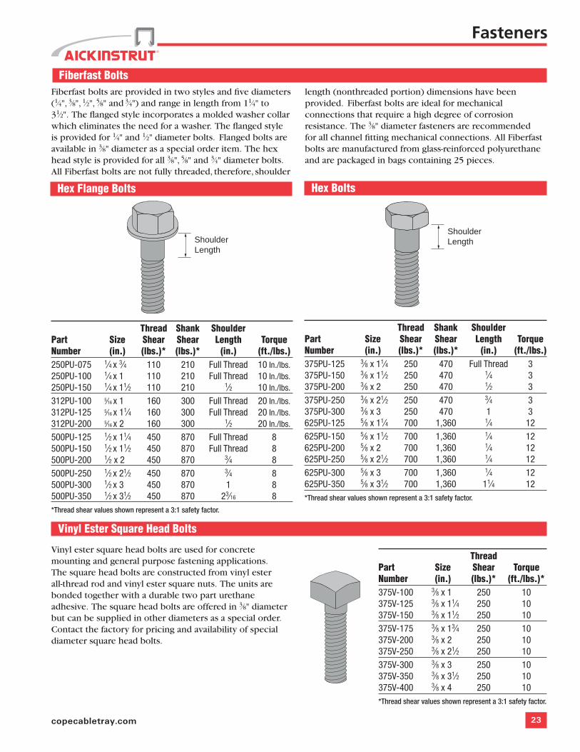
Hex Flange Bolts Hex Bolts
Thread Shank Shoulder Part Size Shear Shear Length TorqueNumber (in.) (lbs.)* (lbs.)* (in.) (ft./lbs.)250PU-075 1⁄4 x 3⁄4 110 210 Full Thread 10 In./lbs.250PU-100 1⁄4 x 1 110 210 Full Thread 10 In./lbs.250PU-150 1⁄4 x 11⁄2 110 210 1⁄2 10 In./lbs.
312PU-100 5⁄16 x 1 160 300 Full Thread 20 In./lbs.312PU-125 5⁄16 x 11⁄4 160 300 Full Thread 20 In./lbs.312PU-200 5⁄16 x 2 160 300 1⁄2 20 In./lbs.
500PU-125 1⁄2 x 11⁄4 450 870 Full Thread 8500PU-150 1⁄2 x 11⁄2 450 870 Full Thread 8500PU-200 1⁄2 x 2 450 870 3⁄4 8500PU-250 1⁄2 x 21⁄2 450 870 3⁄4 8500PU-300 1⁄2 x 3 450 870 1 8500PU-350 1⁄2 x 31⁄2 450 870 23⁄16 8*Thread shear values shown represent a 3:1 safety factor.
Thread Shank Shoulder Part Size Shear Shear Length TorqueNumber (in.) (lbs.)* (lbs.)* (in.) (ft./lbs.)375PU-125 3⁄8 x 11⁄4 250 470 Full Thread 3375PU-150 3⁄8 x 11⁄2 250 470 1⁄4 3375PU-200 3⁄8 x 2 250 470 1⁄2 3375PU-250 3⁄8 x 21⁄2 250 470 3⁄4 3375PU-300 3⁄8 x 3 250 470 1 3625PU-125 5⁄8 x 11⁄4 700 1,360 1⁄4 12625PU-150 5⁄8 x 11⁄2 700 1,360 1⁄4 12625PU-200 5⁄8 x 2 700 1,360 1⁄4 12625PU-250 5⁄8 x 21⁄2 700 1,360 1⁄4 12625PU-300 5⁄8 x 3 700 1,360 1⁄4 12625PU-350 5⁄8 x 31⁄2 700 1,360 11⁄4 12*Thread shear values shown represent a 3:1 safety factor.
Vinyl Ester Square Head Bolts
Vinyl ester square head bolts are used for concrete mounting and general purpose fastening applications. The square head bolts are constructed from vinyl ester all-thread rod and vinyl ester square nuts. The units are bonded together with a durable two part urethane adhesive. The square head bolts are offered in 3⁄8" diameter but can be supplied in other diameters as a special order. Contact the factory for pricing and availability of special diameter square head bolts.
Thread Part Size Shear TorqueNumber (in.) (lbs.)* (ft./lbs.)*375V-100 3⁄8 x 1 250 10375V-125 3⁄8 x 11⁄4 250 10375V-150 3⁄8 x 11⁄2 250 10375V-175 3⁄8 x 13⁄4 250 10375V-200 3⁄8 x 2 250 10375V-250 3⁄8 x 21⁄2 250 10375V-300 3⁄8 x 3 250 10375V-350 3⁄8 x 31⁄2 250 10375V-400 3⁄8 x 4 250 10*Thread shear values shown represent a 3:1 safety factor.
ShoulderLengthShoulder
Length
Fasteners
Fiberfast BoltsFiberfast bolts are provided in two styles and five diameters (1⁄4", 3⁄8", 1⁄2", 5⁄8" and 3⁄4") and range in length from 11⁄4" to 31⁄2". The flanged style incorporates a molded washer collar which eliminates the need for a washer. The flanged style is provided for 1⁄4" and 1⁄2" diameter bolts. Flanged bolts are available in 3⁄8" diameter as a special order item. The hex head style is provided for all 3⁄8", 5⁄8" and 3⁄4" diameter bolts. All Fiberfast bolts are not fully threaded, therefore, shoulder
length (nonthreaded portion) dimensions have been provided. Fiberfast bolts are ideal for mechanical connections that require a high degree of corrosion resistance. The 3⁄8" diameter fasteners are recommended for all channel fitting mechanical connections. All Fiberfast bolts are manufactured from glass-reinforced polyurethane and are packaged in bags containing 25 pieces.
24 Aickinstrut
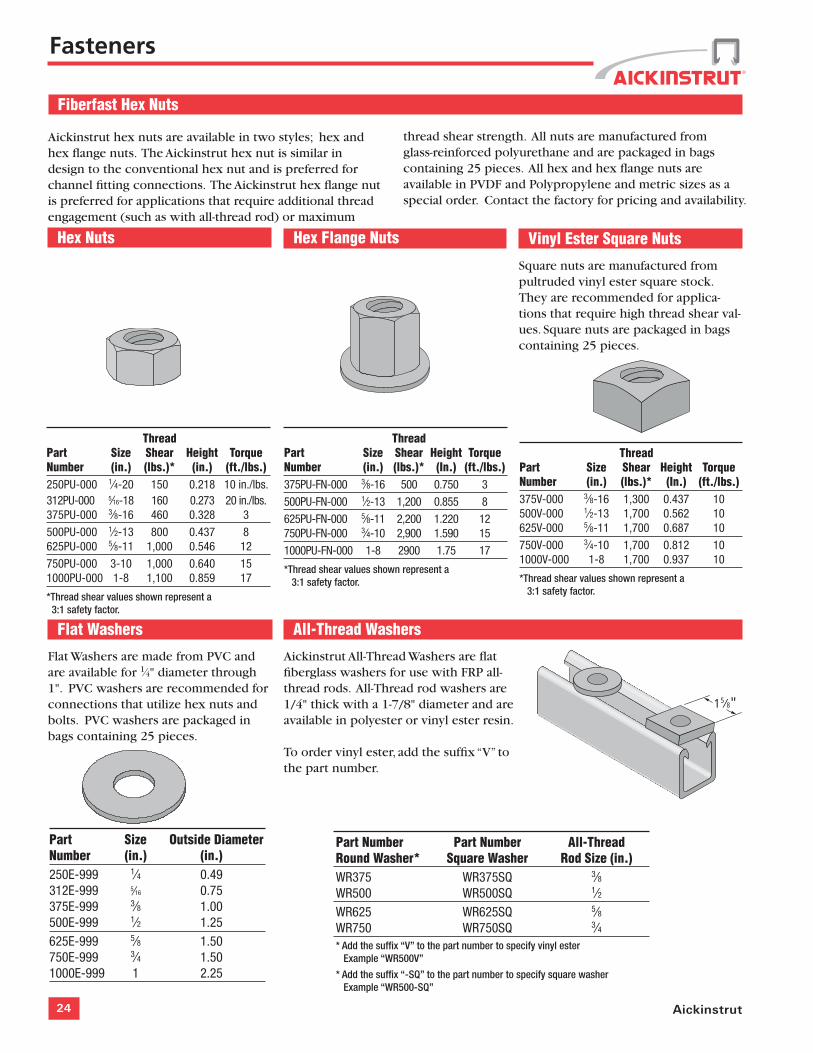
Vinyl Ester Square Nuts
Square nuts are manufactured from pultruded vinyl ester square stock. They are recommended for applica-tions that require high thread shear val-ues. Square nuts are packaged in bags containing 25 pieces.
Flat Washers
Flat Washers are made from PVC and are available for 1⁄4" diameter through 1". PVC washers are recommended for connections that utilize hex nuts and bolts. PVC washers are packaged in bags containing 25 pieces.
Hex Nuts
Part Size Outside DiameterNumber (in.) (in.)250E-999 1⁄4 0.49312E-999 5⁄16 0.75 375E-999 3⁄8 1.00500E-999 1⁄2 1.25625E-999 5⁄8 1.50750E-999 3⁄4 1.501000E-999 1 2.25
Fiberfast Hex Nuts
Hex Flange Nuts
Aickinstrut hex nuts are available in two styles; hex and hex flange nuts. The Aickinstrut hex nut is similar in design to the conventional hex nut and is preferred for channel fitting connections. The Aickinstrut hex flange nut is preferred for applications that require additional thread engagement (such as with all-thread rod) or maximum
thread shear strength. All nuts are manufactured from glass-reinforced polyurethane and are packaged in bags containing 25 pieces. All hex and hex flange nuts are available in PVDF and Polypropylene and metric sizes as a special order. Contact the factory for pricing and availability.
Thread Part Size Shear Height TorqueNumber (in.) (lbs.)* (in.) (ft./lbs.)250PU-000 1⁄4-20 150 0.218 10 in./lbs. 312PU-000 5⁄16-18 160 0.273 20 in./lbs.375PU-000 3⁄8-16 460 0.328 3
500PU-000 1⁄2-13 800 0.437 8625PU-000 5⁄8-11 1,000 0.546 12
750PU-000 3-10 1,000 0.640 151000PU-000 1-8 1,100 0.859 17
*Thread shear values shown represent a 3:1 safety factor.
Thread Part Size Shear Height TorqueNumber (in.) (lbs.)* (In.) (ft./lbs.)375PU-FN-000 3⁄8-16 500 0.750 3
500PU-FN-000 1⁄2-13 1,200 0.855 8
625PU-FN-000 5⁄8-11 2,200 1.220 12750PU-FN-000 3⁄4-10 2,900 1.590 15
1000PU-FN-000 1-8 2900 1.75 17
*Thread shear values shown represent a 3:1 safety factor.
Thread Part Size Shear Height TorqueNumber (in.) (lbs.)* (In.) (ft./lbs.)375V-000 3⁄8-16 1,300 0.437 10500V-000 1⁄2-13 1,700 0.562 10625V-000 5⁄8-11 1,700 0.687 10
750V-000 3⁄4-10 1,700 0.812 101000V-000 1-8 1,700 0.937 10
*Thread shear values shown represent a 3:1 safety factor.
Fasteners
All-Thread Washers
Aickinstrut All-Thread Washers are flat fiberglass washers for use with FRP all-thread rods. All-Thread rod washers are 1/4" thick with a 1-7/8" diameter and are available in polyester or vinyl ester resin. To order vinyl ester, add the suffix “V” to the part number.
Part Number Part Number All-ThreadRound Washer* Square Washer Rod Size (in.)WR375 WR375SQ 3⁄8WR500 WR500SQ 1⁄2WR625 WR625SQ 5⁄8WR750 WR750SQ 3⁄4* Add the suffix “V” to the part number to specify vinyl ester Example “WR500V”
* Add the suffix “-SQ” to the part number to specify square washer Example “WR500-SQ”
15⁄8"
25copecabletray.com
Fasteners
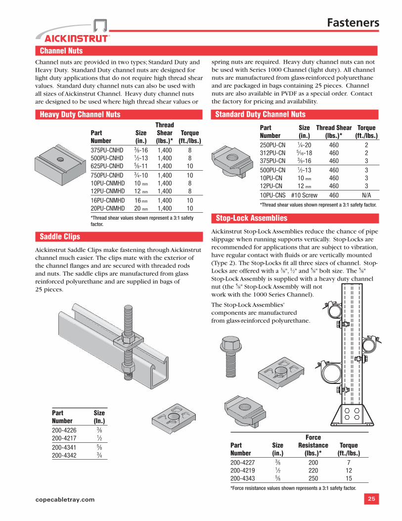
Channel NutsChannel nuts are provided in two types; Standard Duty and Heavy Duty. Standard Duty channel nuts are designed for light duty applications that do not require high thread shear values. Standard duty channel nuts can also be used with all sizes of Aickinstrut Channel. Heavy duty channel nuts are designed to be used where high thread shear values or
spring nuts are required. Heavy duty channel nuts can not be used with Series 1000 Channel (light duty). All channel nuts are manufactured from glass-reinforced polyurethane and are packaged in bags containing 25 pieces. Channel nuts are also available in PVDF as a special order. Contact the factory for pricing and availability.
Standard Duty Channel NutsHeavy Duty Channel Nuts
Part Size Thread Shear TorqueNumber (in.) (lbs.)* (ft./lbs.)250PU-CN 1⁄4-20 460 2312PU-CN 5⁄16-18 460 2375PU-CN 3⁄8-16 460 3500PU-CN 1⁄2-13 460 310PU-CN 10 mm 460 312PU-CN 12 mm 460 310PU-CNS #10 Screw 460 N/A*Thread shear values shown represent a 3:1 safety factor.
Thread Part Size Shear TorqueNumber (in.) (lbs.)* (ft./lbs.)375PU-CNHD 3⁄8-16 1,400 8500PU-CNHD 1⁄2-13 1,400 8625PU-CNHD 5⁄8-11 1,400 10750PU-CNHD 3⁄4-10 1,400 1010PU-CNMHD 10 mm 1,400 812PU-CNMHD 12 mm 1,400 816PU-CNMHD 16 mm 1,400 1020PU-CNMHD 20 mm 1,400 10*Thread shear values shown represent a 3:1 safety factor.
Part SizeNumber (In.)200-4226 3⁄8200-4217 1⁄2200-4341 5⁄8200-4342 3⁄4
Stop-Lock Assemblies
Aickinstrut Stop-Lock Assemblies reduce the chance of pipe slippage when running supports vertically. Stop-Locks are recommended for applications that are subject to vibration, have regular contact with fluids or are vertically mounted (Type 2). The Stop-Locks fit all three sizes of channel. Stop-Locks are offered with a 3⁄8", 1⁄2" and 5⁄8" bolt size. The 5⁄8" Stop-Lock Assembly is supplied with a heavy duty channel nut (the 5⁄8" Stop-Lock Assembly will not work with the 1000 Series Channel).
The Stop-Lock Assemblies' components are manufactured from glass-reinforced polyurethane.
Saddle Clips
Aickinstrut Saddle Clips make fastening through Aickinstrut channel much easier. The clips mate with the exterior of the channel flanges and are secured with threaded rods and nuts. The saddle clips are manufactured from glass reinforced polyurethane and are supplied in bags of 25 pieces.
ForcePart Size Resistance TorqueNumber (in.) (lbs.)* (ft./lbs.)200-4227 3⁄8 200 7200-4219 1⁄2 220 12200-4343 5⁄8 250 15*Force resistance values shown represents a 3:1 safety factor.
26 Aickinstrut
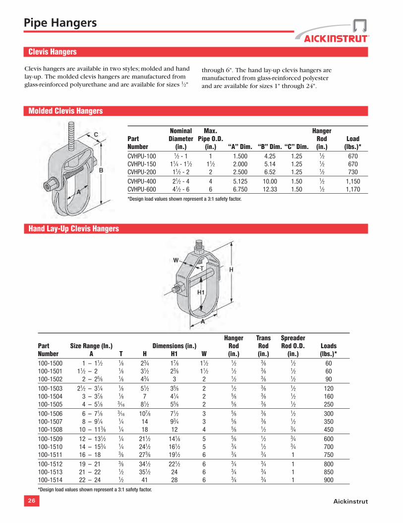
Clevis hangers are available in two styles; molded and hand lay-up. The molded clevis hangers are manufactured from glass-reinforced polyurethane and are available for sizes 1⁄2"
through 6". The hand lay-up clevis hangers are manufactured from glass-reinforced polyester and are available for sizes 1" through 24".
Molded Clevis Hangers
Hand Lay-Up Clevis Hangers
Nominal Max. Hanger Part Diameter Pipe O.D. Rod LoadNumber (in.) (in.) “A” Dim. “B” Dim. “C” Dim. (in.) (lbs.)*CVHPU-100 1⁄2 - 1 1 1.500 4.25 1.25 1⁄2 670CVHPU-150 11⁄4 - 11⁄2 11⁄2 2.000 5.14 1.25 1⁄2 670CVHPU-200 11⁄2 - 2 2 2.500 6.52 1.25 1⁄2 730CVHPU-400 21⁄2 - 4 4 5.125 10.00 1.50 1⁄2 1,150CVHPU-600 41⁄2 - 6 6 6.750 12.33 1.50 1⁄2 1,170*Design load values shown represent a 3:1 safety factor.
Hanger Trans Spreader Part Size Range (In.) Dimensions (in.) Rod Rod Rod O.D. LoadsNumber A T H H1 W (in.) (in.) (in.) (lbs.)*100-1500 1 – 11⁄2 1⁄8 23⁄4 17⁄8 11⁄2 1⁄2 3⁄8 1⁄2 60100-1501 11⁄2 – 2 1⁄8 31⁄2 23⁄8 11⁄2 1⁄2 3⁄8 1⁄2 60100-1502 2 – 25⁄8 1⁄8 43⁄4 3 2 1⁄2 3⁄8 1⁄2 90100-1503 21⁄2 – 31⁄4 1⁄8 51⁄2 35⁄8 2 1⁄2 3⁄8 1⁄2 120100-1504 3 – 37⁄8 1⁄8 7 41⁄4 2 5⁄8 3⁄8 1⁄2 160100-1505 4 – 51⁄8 3⁄16 81⁄2 55⁄8 2 5⁄8 3⁄8 1⁄2 250100-1506 6 – 71⁄8 3⁄16 107⁄8 71⁄2 3 5⁄8 3⁄8 1⁄2 300100-1507 8 – 91⁄4 1⁄4 14 93⁄4 3 5⁄8 3⁄8 1⁄2 350100-1508 10 – 113⁄8 1⁄4 18 12 4 5⁄8 1⁄2 3⁄4 450100-1509 12 – 131⁄2 1⁄4 211⁄2 141⁄8 5 5⁄8 1⁄2 3⁄4 600100-1510 14 – 153⁄4 1⁄4 241⁄2 161⁄2 5 3⁄4 1⁄2 3⁄4 700100-1511 16 – 18 3⁄8 273⁄8 191⁄2 6 3⁄4 3⁄4 1 750100-1512 19 – 21 3⁄8 341⁄2 221⁄2 6 3⁄4 3⁄4 1 800100-1513 21 – 22 1⁄2 351⁄2 24 6 3⁄4 3⁄4 1 850100-1514 22 – 24 1⁄2 41 28 6 3⁄4 3⁄4 1 900*Design load values shown represent a 3:1 safety factor.
Pipe Hangers
Clevis Hangers
27copecabletray.com
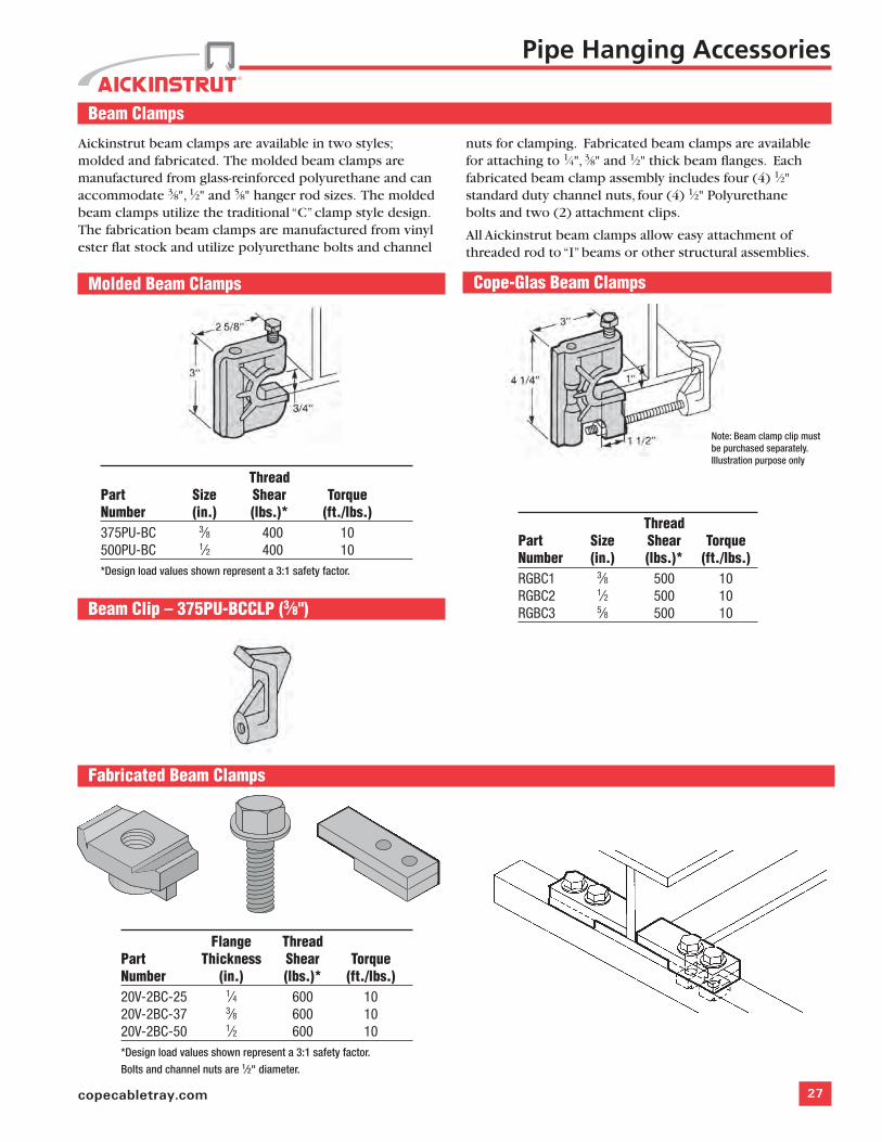
Beam Clamps
Aickinstrut beam clamps are available in two styles; molded and fabricated. The molded beam clamps are manufactured from glass-reinforced polyurethane and can accommodate 3⁄8", 1⁄2" and 5⁄8" hanger rod sizes. The molded beam clamps utilize the traditional “C” clamp style design. The fabrication beam clamps are manufactured from vinyl ester flat stock and utilize polyurethane bolts and channel
nuts for clamping. Fabricated beam clamps are available for attaching to 1⁄4", 3⁄8" and 1⁄2" thick beam flanges. Each fabricated beam clamp assembly includes four (4) 1⁄2" standard duty channel nuts, four (4) 1⁄2" Polyurethane bolts and two (2) attachment clips.
All Aickinstrut beam clamps allow easy attachment of threaded rod to “I” beams or other structural assemblies.
Molded Beam Clamps Cope-Glas Beam Clamps
Beam Clip – 375PU-BCCLP (3⁄8")
Fabricated Beam Clamps
Thread Part Size Shear TorqueNumber (in.) (lbs.)* (ft./lbs.)375PU-BC 3⁄8 400 10500PU-BC 1⁄2 400 10*Design load values shown represent a 3:1 safety factor.
Thread Part Size Shear TorqueNumber (in.) (lbs.)* (ft./lbs.)RGBC1 3⁄8 500 10RGBC2 1⁄2 500 10RGBC3 5⁄8 500 10
Flange Thread Part Thickness Shear TorqueNumber (in.) (lbs.)* (ft./lbs.)20V-2BC-25 1⁄4 600 1020V-2BC-37 3⁄8 600 1020V-2BC-50 1⁄2 600 10*Design load values shown represent a 3:1 safety factor.
Bolts and channel nuts are 1⁄2" diameter.
Pipe Hanging Accessories
Note: Beam clamp clip must be purchased separately. Illustration purpose only
28 Aickinstrut
Pipe Supports
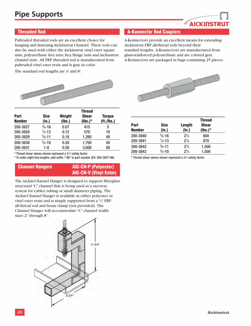
Threaded Rod
Pultruded threaded rods are an excellent choice for hanging and fastening Aickinstrut Channel. These rods can also be used with either the Aickinstrut vinyl ester square nuts, polyurethane hex nuts, hex flange nuts and Aickinstrut channel nuts. All FRP threaded rod is manufactured from pultruded vinyl ester resin and is gray in color.
The standard rod lengths are 4' and 8'.
A-Konnector Rod Couplers
A-Konnectors provide an excellent means for extending Aickinstrut FRP all-thread rods beyond their standard lengths. A-Konnectors are manufactured from glass-reinforced polyurethane and are colored gray. A-Konnectors are packaged in bags containing 25 pieces.
Thread Part Size Weight Shear TorqueNumber (in.) (lbs.) (lbs.)* (ft./lbs.)200-3827 3⁄8-16 0.07 415 5200-3828 1⁄2-13 0.12 570 10200-3829 5⁄8-11 0.18 1,260 40200-3830 3⁄4-10 0.28 1,700 50200-3831 1-8 0.50 3,000 60* Thread shear values shown represent a 3:1 safety factor. * To order eight foot lengths, add suffix “-96” to part number (EX: 200-3827-96)
ThreadPart Size Length ShearNumber (in.) (ln.) (lbs.)*200-3840 3⁄8-16 21⁄4 800200-3841 1⁄2-13 21⁄4 870200-3842 5⁄8-11 21⁄4 1,500200-3843 3⁄4-10 21⁄4 1,500* Thread shear values shown represent a 3:1 safety factor.
Channel Hangers AIC-CH-P (Polyester) AIC-CH-V (Vinyl Ester)
The Aickin-Channel Hanger is designed to support fiberglass structural “C” channel that is being used as a raceway system for cables, tubing or small diameter piping. The Aickin-Channel Hanger is available in either polyester or vinyl ester resin and is simply supported from a 1⁄2" FRP all-thread rod and beam clamp (not provided). The Channel Hanger will accommodate “C” channel width sizes 2" through 8".
29copecabletray.com
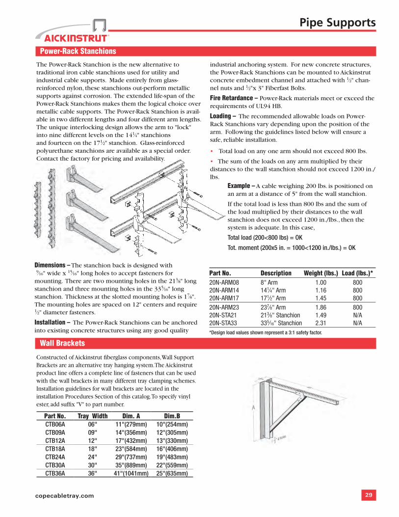
Power-Rack Stanchions
The Power-Rack Stanchion is the new alternative to traditional iron cable stanchions used for utility and industrial cable supports. Made entirely from glass-reinforced nylon, these stanchions out-perform metallic supports against corrosion. The extended life-span of the Power-Rack Stanchions makes them the logical choice over metallic cable supports. The Power-Rack Stanchion is avail-able in two different lengths and four different arm lengths. The unique interlocking design allows the arm to "lock" into nine different levels on the 141⁄4" stanchions and fourteen on the 171⁄2" stanchion. Glass-reinforced polyurethane stanchions are available as a special order. Contact the factory for pricing and availability.
Part No. Description Weight (lbs.) Load (lbs.)*20N-ARM08 8" Arm 1.00 80020N-ARM14 141⁄4" Arm 1.16 80020N-ARM17 171⁄2" Arm 1.45 80020N-ARM23 237⁄8" Arm 1.86 80020N-STA21 213⁄8" Stanchion 1.49 N/A20N-STA33 335⁄16" Stanchion 2.31 N/A*Design load values shown represent a 3:1 safety factor.
industrial anchoring system. For new concrete structures, the Power-Rack Stanchions can be mounted to Aickinstrut concrete embedment channel and attached with 1⁄2" chan-nel nuts and 1⁄2"x 3" Fiberfast Bolts.
Fire Retardance – Power-Rack materials meet or exceed the requirements of UL94 HB.
Loading – The recommended allowable loads on Power-Rack Stanchions vary depending upon the position of the arm. Following the guidelines listed below will ensure a safe, reliable installation.
• Total load on any one arm should not exceed 800 lbs.
• The sum of the loads on any arm multiplied by their distances to the wall stanchion should not exceed 1200 in./lbs.
Example – A cable weighing 200 lbs. is positioned on an arm at a distance of 5" from the wall stanchion.
If the total load is less than 800 lbs and the sum of the load multiplied by their distances to the wall stanchion does not exceed 1200 in./lbs., then the system is adequate. In this case,
Total load (200<800 lbs) = OK
Tot. moment (200x5 in. = 1000<1200 in./lbs.) = OK
Dimensions – The stanchion back is designed with 9⁄16" wide x 15⁄16" long holes to accept fasteners for mounting. There are two mounting holes in the 213⁄8" long stanchion and three mounting holes in the 335⁄16" long stanchion. Thickness at the slotted mounting holes is 17⁄8". The mounting holes are spaced on 12" centers and require 1⁄2" diameter fasteners.
Installation – The Power-Rack Stanchions can be anchored into existing concrete structures using any good quality
Wall Brackets
Pipe Supports
Constructed of Aickinstrut fiberglass components, Wall Support Brackets are an alternative tray hanging system. The Aickinstrut product line offers a complete line of fasteners that can be used with the wall brackets in many different tray clamping schemes. Installation guidelines for wall brackets are located in the installation Procedures Section of this catalog. To specify vinyl ester, add suffix "V" to part number.
Part No. Tray Width Dim. A Dim.BCTB06A 06" 11"(279mm) 10"(254mm) CTB09A 09" 14"(356mm) 12"(305mm) CTB12A 12" 17"(432mm) 13"(330mm) CTB18A 18" 23"(584mm) 16"(406mm)CTB24A 24" 29"(737mm) 19"(483mm)CTB30A 30" 35"(889mm) 22"(559mm)CTB36A 36" 41"(1041mm) 25"(635mm)
30 Aickinstrut
Instrument & Pipe Stands
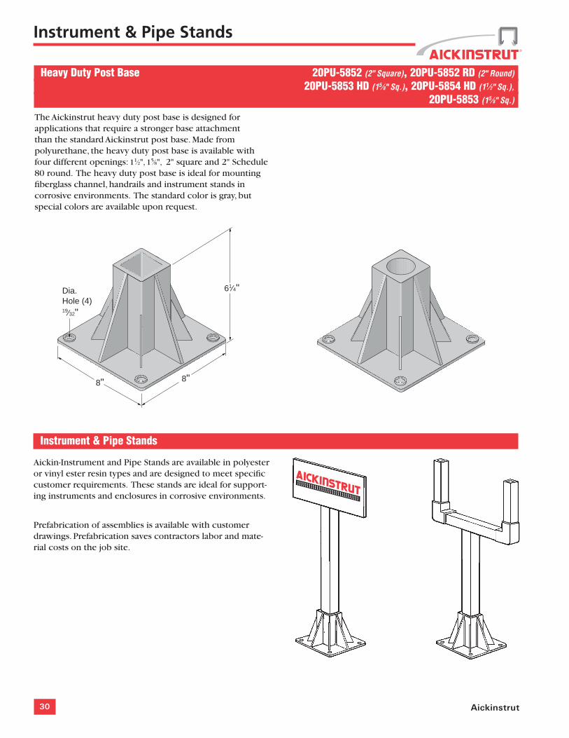
Heavy Duty Post Base 20PU-5852 (2" Square), 20PU-5852 RD (2" Round)
20PU-5853 HD (15⁄8" Sq.), 20PU-5854 HD (11⁄2" Sq.),
20PU-5853 (15⁄8" Sq.)
The Aickinstrut heavy duty post base is designed for applications that require a stronger base attachment than the standard Aickinstrut post base. Made from polyurethane, the heavy duty post base is available with four different openings: 11⁄2", 15⁄8", 2" square and 2" Schedule 80 round. The heavy duty post base is ideal for mounting fiberglass channel, handrails and instrument stands in corrosive environments. The standard color is gray, but special colors are available upon request.
8" 8"
Dia.Hole (4)19⁄32"
61⁄4"
Instrument & Pipe Stands
Aickin-Instrument and Pipe Stands are available in polyester or vinyl ester resin types and are designed to meet specific customer requirements. These stands are ideal for support-ing instruments and enclosures in corrosive environments.
Prefabrication of assemblies is available with customer drawings. Prefabrication saves contractors labor and mate-rial costs on the job site.
31copecabletray.com
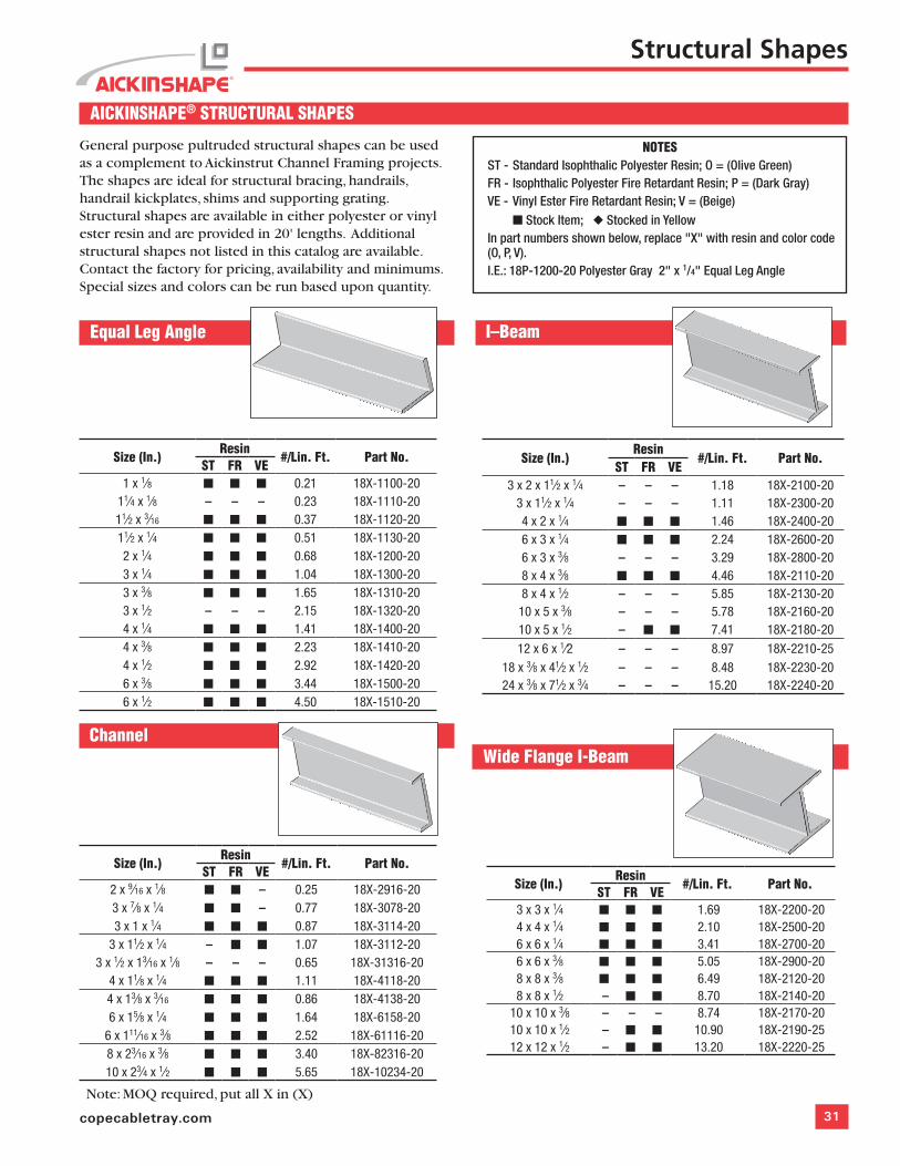
Channel
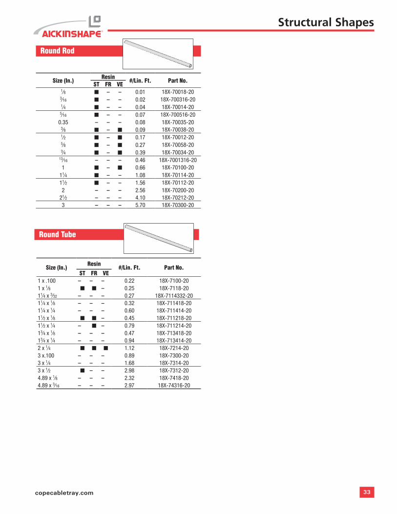
AICKINSHAPE® STRUCTURAL SHAPES
General purpose pultruded structural shapes can be used as a complement to Aickinstrut Channel Framing projects. The shapes are ideal for structural bracing, handrails, handrail kickplates, shims and supporting grating. Structural shapes are available in either polyester or vinyl ester resin and are provided in 20' lengths. Additional structural shapes not listed in this catalog are available. Contact the factory for pricing, availability and minimums. Special sizes and colors can be run based upon quantity.
Equal Leg Angle
NOTESST - Standard Isophthalic Polyester Resin; O = (Olive Green)FR - Isophthalic Polyester Fire Retardant Resin; P = (Dark Gray)VE - Vinyl Ester Fire Retardant Resin; V = (Beige) n Stock Item; u Stocked in YellowIn part numbers shown below, replace "X" with resin and color code (O, P, V). I.E.: 18P-1200-20 Polyester Gray 2" x 1/4" Equal Leg Angle
Structural Shapes
I–Beam
Size (In.)Resin
#/Lin. Ft. Part No.ST FR VE
3 x 2 x 11⁄2 x 1⁄4 – – – 1.18 18X-2100-203 x 11⁄2 x 1⁄4 – – – 1.11 18X-2300-204 x 2 x 1⁄4 n n n 1.46 18X-2400-206 x 3 x 1⁄4 n n n 2.24 18X-2600-206 x 3 x 3⁄8 – – – 3.29 18X-2800-208 x 4 x 3⁄8 n n n 4.46 18X-2110-208 x 4 x 1⁄2 – – – 5.85 18X-2130-20
10 x 5 x 3⁄8 – – – 5.78 18X-2160-2010 x 5 x 1⁄2 – n n 7.41 18X-2180-20
12 x 6 x 1⁄2 – – – 8.97 18X-2210-2518 x 3⁄8 x 41⁄2 x 1⁄2 – – – 8.48 18X-2230-2024 x 3⁄8 x 71⁄2 x 3⁄4 – – – 15.20 18X-2240-20
Size (In.)Resin
#/Lin. Ft. Part No.ST FR VE
2 x 9⁄16 x 1⁄8 n n – 0.25 18X-2916-203 x 7⁄8 x 1⁄4 n n – 0.77 18X-3078-203 x 1 x 1⁄4 n n n 0.87 18X-3114-20
3 x 11⁄2 x 1⁄4 – n n 1.07 18X-3112-203 x 1⁄2 x 13⁄16 x 1⁄8 – – – 0.65 18X-31316-20
4 x 11⁄8 x 1⁄4 n n n 1.11 18X-4118-204 x 13⁄8 x 3⁄16 n n n 0.86 18X-4138-206 x 15⁄8 x 1⁄4 n n n 1.64 18X-6158-20
6 x 111⁄16 x 3⁄8 n n n 2.52 18X-61116-208 x 23⁄16 x 3⁄8 n n n 3.40 18X-82316-2010 x 23⁄4 x 1⁄2 n n n 5.65 18X-10234-20
Size (In.)Resin
#/Lin. Ft. Part No.ST FR VE
1 x 1⁄8 n n n 0.21 18X-1100-2011⁄4 x 1⁄8 – – – 0.23 18X-1110-2011⁄2 x 3⁄16 n n n 0.37 18X-1120-2011⁄2 x 1⁄4 n n n 0.51 18X-1130-202 x 1⁄4 n n n 0.68 18X-1200-203 x 1⁄4 n n n 1.04 18X-1300-203 x 3⁄8 n n n 1.65 18X-1310-203 x 1⁄2 – – – 2.15 18X-1320-204 x 1⁄4 n n n 1.41 18X-1400-204 x 3⁄8 n n n 2.23 18X-1410-204 x 1⁄2 n n n 2.92 18X-1420-206 x 3⁄8 n n n 3.44 18X-1500-206 x 1⁄2 n n n 4.50 18X-1510-20
Wide Flange I-Beam
Size (In.)Resin
#/Lin. Ft. Part No.ST FR VE
3 x 3 x 1⁄4 n n n 1.69 18X-2200-204 x 4 x 1⁄4 n n n 2.10 18X-2500-206 x 6 x 1⁄4 n n n 3.41 18X-2700-206 x 6 x 3⁄8 n n n 5.05 18X-2900-208 x 8 x 3⁄8 n n n 6.49 18X-2120-208 x 8 x 1⁄2 – n n 8.70 18X-2140-20
10 x 10 x 3⁄8 – – – 8.74 18X-2170-2010 x 10 x 1⁄2 – n n 10.90 18X-2190-2512 x 12 x 1⁄2 – n n 13.20 18X-2220-25
Note: MOQ required, put all X in (X)
32 Aickinstrut
Size (In.)Resin
#/Lin. Ft. Part No.ST FR VE
4 x 1 x 1⁄8 – – – 0.85 18X-4118-204 x 1⁄8 x 2 x 1⁄4 n n n 1.52 18X-418214-20
43⁄8 x 13⁄8 x 1⁄8 x 3⁄16 – – – 1.18 18X-438138-2041⁄2 x 13⁄4 x 1⁄8 x 3⁄16 – – – 1.29 18X-412138-20
5 x 2 x 1⁄8 – – – 1.32 18X-5218-2051⁄8 x 21⁄8 x 3⁄16 – – – 1.32 18X-518218-20
61⁄2 x 1⁄4 x 2 x 1⁄2 – – – 3.77 18X-612212-206 x 4 x 1⁄4 – n – 18X-6414-20
Structural Shapes
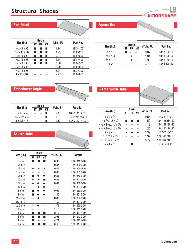
Flat Sheet
Embedment Angle
Size (In.)Resin
#/Lin. Ft. Part No.ST FR VE
1 x 11⁄2 x 1⁄4 – – n 1.00 18X-111214-2011⁄2 x 11⁄2 x 1⁄4 – – n 1.10 18X-11211214-202 x 11⁄2 x 1⁄4 – – n 1.20 18X-211214-20
Square Bar
Size (In.)Resin
#/Lin. Ft. Part No.ST FR VE
1 x 1 n – – 0.87 18X-5100-20
11⁄4 x 11⁄4 – u – 1.31 18X-5125-20
11⁄2 x 11⁄2 – u – 1.98 18X-5150-20
2 x 2 – – – 3.12 18X-5200-20
Rectangular Tube
Size (In.)Resin
#/Lin. Ft. Part No.ST FR VE
1⁄8 x 48 x 96 n n n 1.14 18X-41003⁄16 x 48 x 96 n n n 1.71 18X-42001⁄4 x 48 x 96 n n n 2.34 18X-43003⁄8 x 48 x 96 n n n 3.54 18X-44001⁄2 x 48 x 96 n n n 4.68 18X-45005⁄8 x 48 x 96 – – – 5.79 18X-46003⁄4 x 48 x 96 – – – 6.94 18X-47001 x 48 x 96 – – – 9.27 18X-4800
Square Tube
Size (In.)Resin
#/Lin. Ft. Part No.ST FR VE
1 x 1⁄8 n n n 0.32 18X-3100-2011⁄8 x 1⁄8 – – – 0.37 18X-3200-2011⁄4 x 1⁄8 – – – 0.41 18X-3300-2011⁄4 x 1⁄4 – – – 0.68 18X-3310-2011⁄2 x 1⁄8 n u u 0.54 18X-3400-2011⁄2 x 1⁄4 – – n 0.98 18X-3410-2013⁄4 x 1⁄8 – u u 0.63 18X-3500-2013⁄4 x 1⁄4 – u u 1.10 18X-3510-202 x 1⁄8 n u u 0.69 18X-3600-202 x 1⁄4 n u u 1.40 18X-3610-20
21⁄4 x 1⁄8 – u – 0.83 18X-3800-2021⁄4 x 1⁄4 – – – 1.56 18X-3810-2021⁄2 x 1⁄4 – u – 1.79 18X-3900-203 x 1⁄8 – – – 1.12 18X-3110-203 x 1⁄4 n n n 2.15 18X-3111-204 x 1⁄4 n n n 2.93 18X-3120-204 x 3⁄8 n – – 4.24 18X-3121-206 x 3⁄8 n n n 6.42 18X-3140-20
33copecabletray.com
Round Rod
Size (In.)Resin
#/Lin. Ft. Part No.ST FR VE
1⁄8 n – – 0.01 18X-70018-203⁄16 n – – 0.02 18X-700316-201⁄4 n – – 0.04 18X-70014-20
5⁄16 n – – 0.07 18X-700516-200.35 – – – 0.08 18X-70035-20
3⁄8 n – n 0.09 18X-70038-201⁄2 n – n 0.17 18X-70012-205⁄8 n – n 0.27 18X-70058-203⁄4 n – n 0.39 18X-70034-20
13⁄16 – – – 0.46 18X-7001316-201 n – n 0.66 18X-70100-20
11⁄4 n – – 1.08 18X-70114-2011⁄2 n – – 1.56 18X-70112-202 – – – 2.56 18X-70200-20
21⁄2 – – – 4.10 18X-70212-203 – – – 5.70 18X-70300-20
Structural Shapes
Round Tube
Size (In.)Resin
#/Lin. Ft. Part No.ST FR VE
1 x .100 – – – 0.22 18X-7100-201 x 1⁄8 n n – 0.25 18X-7118-2011⁄4 x 3⁄32 – – – 0.27 18X-7114332-2011⁄4 x 1⁄8 – – – 0.32 18X-711418-2011⁄4 x 1⁄4 – – – 0.60 18X-711414-2011⁄2 x 1⁄8 n n – 0.45 18X-711218-2011⁄2 x 1⁄4 – n – 0.79 18X-711214-2013⁄4 x 1⁄8 – – – 0.47 18X-713418-2013⁄4 x 1⁄4 – – – 0.94 18X-713414-202 x 1⁄4 n n n 1.12 18X-7214-203 x.100 – – – 0.89 18X-7300-203 x 1⁄4 – – – 1.68 18X-7314-203 x 1⁄2 n – – 2.98 18X-7312-204.89 x 1⁄8 – – – 2.32 18X-7418-204.89 x 3⁄16 – – – 2.97 18X-74316-20
34 Aickinstrut
NOTES
35copecabletray.com
Part Number Index
Channel Framing 10-1520E-1000 ............................................ 1120E-1200 ............................................ 1120E-2000 ............................................ 1120E-2200 ............................................ 1120E-2300 ............................................ 1120P-1000 ............................................ 1120P-1100 ............................................ 1120P-1200 ............................................ 1120P-1300 ............................................ 1120P-1500 ............................................ 1120P-1600 ............................................ 1120P-1700 ............................................ 1120P-1800 ............................................ 1120P-2000 ............................................ 1120P-2000-SST..................................... 1120P-2100 ............................................ 1120P-2100-SST..................................... 1120P-2200 ............................................ 1120P-2200-SST..................................... 1120P-2300 ............................................ 1120P-2300-SST..................................... 1120V-1000 ............................................ 1120V-1100 ............................................ 1120V-1200 ............................................ 1120V-1300 ............................................ 1120V-1500 ............................................ 1120V-1600 ............................................ 1120V-1700 ............................................ 1120V-1800 ............................................ 1120V-2000 ............................................ 1120V-2000-SST ..................................... 1120V-2100 ............................................ 1120V-2100-SST ..................................... 1120V-2200 ............................................ 1120V-2200-SST ..................................... 1120V-2300 ............................................ 1120V-2300-SST ..................................... 11
Fittings & Accessories 16-1920E-5000 ............................................ 2320P-2500 ............................................ 1620P-2502 ............................................ 1620P-2504 ............................................ 1620P-2506 ............................................ 1620P-2508 ............................................ 1620P-2510 ............................................ 1720P-2512 ............................................ 1720P-2514 ............................................ 1720P-2516 ............................................ 1720P-2518 ............................................ 1720P-2520 ............................................ 1720P-2522 ............................................ 1720P-2524 ............................................ 1720P-2526 ............................................ 1720P-2528 ............................................ 1820P-2530 ............................................ 1820P-2534 ............................................ 1820P-2540 ............................................ 1820P-2542 ............................................ 1820P-2541 ............................................ 1820P-2800 ............................................ 1620P-2802 ............................................ 1620P-2804 ............................................ 1620P-2806 ............................................ 1620P-2808 ............................................ 1620P-2810L/R ....................................... 1720P-2812 ............................................ 1720P-2814 ............................................ 1720P-2816L/R ....................................... 1720P-2818 ............................................ 1720P-2820 ............................................ 17
20P-2822 ............................................ 1720P-2824 ............................................ 1720P-2826 ............................................ 1720P-2828 ............................................ 1820P-2830 ............................................ 1820P-2834 ............................................ 1820P-2840 ............................................ 1820PP-5853 .......................................... 1920PP-5854 ......................................... 1920PP-5855 ......................................... 1920PP-5903 .......................................... 1920PP-5904 ......................................... 1920PP-5905 ......................................... 1920PU-5853 .......................................... 1920PU-5854 ......................................... 1920PU-5855 ......................................... 1920PU-5903 .......................................... 1920PU-5904 .......................................... 1920PU-5905 ......................................... 1920V-2500 ............................................ 1620V-2502 ............................................ 1620V-2504 ............................................ 1620V-2506 ............................................ 1620V-2508 ............................................ 1620V-2510 ............................................ 1720V-2512 ............................................ 1720V-2514 ............................................ 1720V-2516 ............................................ 1720V-2518 ............................................ 1720V-2520 ............................................ 1720V-2522 ............................................ 1720V-2524 ............................................ 1720V-2526 ............................................ 1720V-2528 ............................................ 1820V-2530 ............................................ 1820V-2534 ............................................ 1820V-2540 ............................................ 1820V-2541 ............................................ 1820V-2800 ............................................ 1620V-2802 ............................................ 1620V-2804 ............................................ 1620V-2806 ............................................ 1620V-2808 ............................................ 1620V-2810L/R ....................................... 1720V-2812 ............................................ 1720V-2814 ............................................ 1720V-2816L/R ....................................... 1720V-2818 ............................................ 1720V-2820 ............................................ 1720V-2822 ............................................ 1720V-2824 ............................................ 1720V-2826 ............................................ 1720V-2828 ............................................ 1820V-2830 ............................................ 1820V-2834 ............................................ 1820V-2840 ............................................ 1820V-2542 ............................................ 1820V-2541 ............................................ 1850PU-1508 .......................................... 1950PU-2008 .......................................... 1950PU-2045 .......................................... 1950PU-2090 .......................................... 1950PU-2538 .......................................... 1950PU-2538 .......................................... 1850PU-2611 .......................................... 1850PU-2611-SP .................................... 1850PU-2613 .......................................... 1850PU-2616 .......................................... 1650PU-2636 .......................................... 1950PU-2636A ........................................ 1950PU-2636B ........................................ 1950PU-2936 .......................................... 19
50PU-500SP ........................................ 23200-3100 thru 200-3140 .................... 20AIC-EC ................................................. 23PCR-050 thru PCR-800 ........................ 21PS050 thru PS1800 ............................. 21UB-050 thru UB-600 ............................ 23
Fasteners 23-2510PU-CN ............................................. 2510PU-CNMHD ...................................... 2510PU-CNS ........................................... 2512PU-CN ............................................. 2512PU-CNMHD ...................................... 2518PU-CNMHD ...................................... 25200-4226 thru 200-4343 .................... 2520PU-CNMHD ...................................... 25250E-999 ............................................ 24250PU Series Bolts .............................. 23250PU-000 .......................................... 24250PU-CN ........................................... 25312PU-CN ........................................... 25375E-999 ............................................ 24375PU Series Bolts .............................. 23375PU-000 .......................................... 24375PU-CN ........................................... 25375PU-CNHD ....................................... 25375PU-FN-000 .................................... 24375V Series Bolts ................................ 23375V-000 ............................................ 24500E-999 ............................................ 24500PU Series Bolts .............................. 23500PU-000 .......................................... 24500PU-CN ........................................... 25500PU-CNHD ....................................... 25500PU-FN-000 .................................... 24500V-000 ............................................ 24625E-999 ............................................ 24625PU Series Bolts .............................. 23625PU-000 .......................................... 24625PU-CNHD ....................................... 25625PU-FN-000 .................................... 24625V-000 ............................................ 24750E-999 ............................................ 24750PU-000 .......................................... 24750PU-CNHD ....................................... 25750PU-FN-000 .................................... 24750V-000 ............................................ 241000E-999 .......................................... 241000PU-000 ........................................ 241000PU-FN-000 .................................. 241000V-000 .......................................... 24WR375 thru WR750 ............................. 24WR375SQ thru WR750SQ .................... 24
Pipe Hangers 26CVHPU-100 thru CVHPU-600 ............... 26100-1500 thru 100-1514 .................... 26
Pipe Hanging Accessories 27-28200-3827 thru 200-3831 .................... 28200-3840 thru 200-3843 .................... 2820V-2BC-25 ........................................ 2720V-2BC-37 ........................................ 2720V-2BC-50 ........................................ 27375PU-BC ............................................ 27500PU-BC ............................................ 27RGBC-1 ............................................... 27RGBC-2 ............................................... 27RGBC-3 ............................................... 27
Pipe Supports 28-3020N-ARM08 ......................................... 30
20N-ARM14 ......................................... 3020N-ARM17 ......................................... 3020N-ARM23 ......................................... 3020N-STA21 .......................................... 3020N-STA33 .......................................... 30AIC-CH-P (Polyester) ............................ 28AIC-CH-V (Vinyl Ester) .......................... 28Wall Brackets ....................................... 29
Instrument & Pipe Stands 3020PU-5852 .......................................... 3020PU-5852 RD .................................... 3020PU-5853 HD .................................... 3020PU-5854 HD .................................... 30
Structural Shapes 31-33Channel ............................................... 31Embedment Angle................................ 32Equal Leg Angle ................................... 31Flat Sheet ............................................ 32Handrail Components........................... 33I–Beam ................................................ 31Rectangular Tube ................................. 32Round Rod ........................................... 33Round Tube .......................................... 33Square Bar .......................................... 32Square Tube......................................... 32Wide Flange I-Beam ............................ 31

16100 South Lathrop Avenue
Harvey, IL 60426
PHONE / 800-882-5543
FAX / 708-339-7814
www.copecabletray.com
©2017 Atkore International, Inc. All rights reserved. ACK-L-1000-1711
®


