Page 1
MANUAL ACTUATORS FOR INDUSTRIAL VALVES
ACTIONARI MANUALE
PENTRU ARMATURI INDUSTRIALE
Str.Bobalna;Nr.57-63;2150 Campina;Romania Tel.40-244-335651; 335652;336571 Fax.40-244-370338;40-244-336641 E-mail:office@ neptun-gears.ro Website:www.neptun-gears.ro
49/2005.rev.2
Page 2
1.GENERALITATI In acest catalog sunt prezentate toate tipurile de actionari manuale aflate in fabricatia S.C. NEPTUN S.A. Campina destinate antrenarii robinetilor industriali. Aceste actionari trebuie folosite atunci cind momentele de actionare necesare nu pot fi satisfacute cu roti de mana de diametru rezonabil montate direct pe robinet. Neptun S.A. fabrica urmatoarele tipuri de actionari: 1.1. Actionari manuale ,,Multi-Tura’’ care sunt: -reductoare manuale conice tip RK -reductoare manuale cilindro-conice tip2CK, cu demultiplicare cilindrica la intrare pentru reducerea momentului de intrare necesar. -reductoare manuale cilindrice tip ICR -roti de mana (sudate sau turnate- vezi anexele). 1.2. Actionari manuale ,,Sfert de tura’’ care sunt: -reductoare manuale melcate tip AM -reductoare manuale cilindro- melcate tip R2CM, cu demultiplicare cilindrica la intrare, pentru reducerea momentului de intrare necesar. -reductoare manuale melcate debraiabile tip RMD, prevazute cu posibilitatea decuplarii arborelui de intrare. -reductoare manuale surub- piulita articulata tip AV. -chei de actionare tip CAM. 2. CONDITII DE UTILIZARE A ACTIONARILOR MANUALE Actionarile manuale pentru robineti industriale pot fi utilizate in urmatoarele conditii: -standard: -33ºC…+45ºC -la cerere: -40ºC…+40ºC. 3.CARACTERISTICI CONSTRUCTIVE 3.1. Angrenaje 3.1.1. Reductoarele manuale ,,Multi-Tura’’ cuprinde: -angrenaje cilindrice facute din otel de imbunatatire- lareductoarele ICR si la reductoarele cilindrice de demultiplicare -un angrenaj conic facut din otel de imbunatatire- la reductoarele RK si2CK.
1. GENERALITIES
This catalogue shows all the types of manual actuators for industrial valves currently made at NEPTUN S.A. Campina. Those actuators are likely to be used whenever the necessary driving torque can not be achieved using a handwheel of reasonable diameter, placed directly onto the valve head. NEPTUN S.A. is currently producing the following types of manual actuators: 1.1. ,,Multi- Turn’’ manual actuators featuring: -RK manual bevel actuators -2CK manual cylindrical- bevel actuators with a cylindrical input demultiplication, to decrease the necessary input torque -ICR manual cylindrical actuators -welded or cast handwheels- see appendices. 1.2. ,,Ouarter- Turn’’ manual actuators featuring: -AM manual worm actuators -R2CM manual cylindrical-bevel actuators with a cylindrical input demultiplication, to decrease the necessary input torque -RMD declutchable worm actuators, provided with the facility of disengaging the input shaft, having a coupling between the worm quadrant and the output shaft. -AV travelling- nut manual actuators -CAM lockable manual lever. 2. CONDITIONS FOR USING THE MANUAL ACTUATORS The manual actuators for industrial valves can be used in the following conditions: -standard: -33ºC…+45ºC -by request: -40ºC…+40ºC. 3. CONSTRUCTIVE FEATURES 3.1. Gears 3.1.1. ,,Multi-Turn’’ manual actuators include:
-cylindrical gears made of heat treatable steel at ICR actuators and at the cylindrica demultiplication geatboxes -a bevel gear made of treatable steel- at RK and ICR gearboxes.
Page 3
3.1.2. Reductoare manuale ,,Sfert de Tura’’ cuprind: -un angrenaj melc- sector melcat la reductoarele tip AM,R2CM si RMD -o transmisie surub- piulita articulata la reductoarele tip AV -melcii si arborii melcati de la reductoarele AM si RMD se executa din: -otel de imbunatatire- AM0…4 si RMD -otel de cementare- AM5…R2CM -sectoarele melcate se executa din fonta cu grafit nodular: Fgn 400-12 (GGG 40- echivalent DIN) -suruburile de antrenare si bucsa de iesire de la reductoarele AV se executa din otel carbon: OLC 45. -piulitele de la reductoarele AV se executa din fonta cu grafit nodular Fgn 400-12 (GGG- 40). 3.2. Carcase 3.2.1. Actionari ,,Multi- Tura’’ Carcasele se executa din: -otel turnat- reductoare RK si 2CK -fonta- reductoare ICR. 3.2.2. Actionari ,,Sfert de Tura’’ -Carcasele se executa din aluminiu turnat sub presiune pentru AM0P, AM1P, AM1.5P,AM2P si fonta pentru restul marimilor. -Cheile de actionare manuala se executa din aluminiu turnat sub presiune sau fonta. 3.3. Piulite si bucse de antrenare -Piulitele si bucsile de antrenare se executa din bronz sau fonta cu grafit nodular. 3.4. Lagare 3.4.1. Actionari ,,Multi- Turna’’ -Lagarele radiale sunt bucse din metal sinterizat sau alama. -Coroana conica e lagaruita pe bile de rulment. -Piulita de antrenare e lagaruita pe rulmenti axiali cu ace. 3.4.2. Actionari ,,Multi- Turna’’ -Lagarele radiale sunt bucse din metal sinterizat sau alama. -Melcul e lagaruit axial pe saibe antifrictiune la AM0P, AM1P, AM1.5P, AM2P si rulmenti axiali cu ace sau cu bile la celelalte marimi.
3.1.2. ,,Quarter- Turn’’ manual actuators include: -a worm gear composed of a worm and a worm quadrant, at the gearboxes AM, R2CM and RMD. -a transmission including a screw and an articulated nut, the gearboxes AV. -the worms and the worm shafts of the gearboxes AM and RMD are made of: -heat treatable steel- AM0…4 and RMD -case hardening steel- AM5…10 -the quadrants are made of ductile iron Fgn 400-12 (GGG 40- DIN equivalent) -the driving screws and the output bush at the AV actuators are made of carbon steel C45. -the nuts at the AV actuators are made of ductile iron GGG 40. 3.2. Housings 3.2.1. ,,Multi- Turn’’ actuators The housings are made of: -cast steel- RK and 2CK -cast iron- ICR. 3.2.2. ,,Quarter- Turn’’ actuators -The housings are made of pressure cast aluminium for AM0P, AM1P, AM1.5P,AM2P, and cast iron for the other sizes. -The lockable manual levers are made of pressure- cast aluminium or cast iron. 3.3. Driving nuts and bushes -The driving nuts and bushes are made of bronze or ductile iron. 3.4. Bearings 3.4.1. ,,Multi- Turn’’ actuators -The radial bearings are sleeves made of sintered metal or brass. -The driving bush is axially supported onto axial needle bearings. -The driving bush is axially supported onto axial needle bearings. 3.4.2. ,,Quarter- Turn’’ actuators -The radial bearings are sleeves made of sintered metal or brass. -The worm is axiaally supported onto antifriction, washers at AM0P,AM1P, AM1.5P, AM2P, and axial needle or ball bearings at the other size.
Page 4
4. UNGERE Ugerea se face cu unsoare consistenta UM 185 Li 2EP. 5. PRINDERE 5.1. Actionari ,,Mult- Tura’’ Flansa de prindere pe armatura este conform ISO 5210. 5.2. Actionari ,,Sfert de Tura’’ Flansa de prindere pe armatura este conform ISO 5211. 5.3. Alte prinderi pot fi executate la cerere. 6. MOTORIZARE Reductoarele manuale se executa si in varianta E cu intrare flansata pentru motorizare. Actionare manuala se face cu roti de mana in conditiile realizarii unui moment la intrare de max. 225 Nm si a unei forte tangentiale de max. 350 N. Alegerea diametrului rotii de mana se face pentru momentul de intrare impus din graficul de mai jos. In cazul in care momentul necesar la intrarea in reductor este mai mare de 225 Nm se impune utilizarea unui demultiplicator ca la tipurile 2CK si R2CM sau actionare cu mecanism ca in variantele E.
4. LUBRICATION Lubrication is done with grease UM 175 Li Ca Pb2. 5. OUTPUT FLANGES 5.1. ,,Multi- Turn’’ actuators Output flanges according to ISO 5210. 5.2. ,,Quarter- Turn’’ Output flanges according to ISO 5211. 5.3. Other output flanges available by request. 6. MOTORISATION The manual actuators can be made in E variant with input flange for motorisation. The manual driving is likely to be done with handwheels provided the input torque necessary is less than 225Nm and the rim effort is under 350N. Whenever the input torque is imposed, the handwheel diameter will be selected from, the geaph bellow. In case the input torque at a gearbox is bigger than 225Nm, it is recommended to use a demultiplication at the types 2CK and R2CM or a motorisation ( E variant).
1000
900
800
700
600
500
400
300250200
190 200180160 1701501401301201101009080706030 4010 20 500
400360300200
Moment intrareInput torque
[N ·m ]
[mm
]D
iam
. roa
ta d
e m
ana
Han
dwhe
el d
iam
eter
[N]Forta tangenta
Rim effort
Mod de utilizare 1. Luati momentul de intrare din catalog. 2. Stabiliti forta tangenta maxima admisibila. 3. Alegeti diametrul rotii.
How to use
1. Get the input torque from the catalogue. 2. Set max. allowable rim effort (swtandard is 360N). 3. Select handwheel diameter
Page 5
Manual actuator catalogue – List of components Lista componenta catalog reductoare manuale
Crt nr.
Range Gama
Actuator Tip red.
Tech. sheet Nr.fisa the.
Date Data
1 RK-0.15 573a 22.07.2004 2 RK-02 683a 27.07.2004 3 RK-03 685b 03.06.2005 4 RK-05 456a 22.07.2004 5 RK-1 742b 27.09.2005 6
Manual multi-turn one-step bevel actuators type RK Reductoare manuale multitura ,conice 1 treapta tip RK
RK-2.1 464a 26.07.2004 7 2CK-2.1 554a 14.09.2004 8 2CK-3 553a 21.10.2002 9 2CK-5 555a 14.09.2004
10 2CK-8 547a 14.09.2004 11 2CK-10 557a 14.09.2004 12 2CK-12 558b 01.09.2006 13 2CK-15 611b 01.09.2006
2CK-15R 354a 10.12.2003 14 2CK-18 630b 01.09.2006 15 2CK-32 602b 01.09.2006
2CK-32RM 907a 01.09.2006 16
Manual multi-turn bevel actuators with input spur de-multiplier type 2CK Reductoare manuale multitura ,conice cu demultiplicator tip 2CK
2CK-50 920 12.01.2005 17 ICR-5 722b 01.09.2006 18 ICR-10 773b 01.09.2006 19 ICR-20 774b 01.09.2006 20
Manual multi-turn spur actuators type ICR Reductoare manuale multitura ,cilindrice tip ICR ICR-50 776b 01.09.2006
21 AM-0P 801 19.02.2004 22 AM-1P 802 19.02.2004 23 AM-1.5P 803 19.02.2004 24
Manual quarter-turn actuators with pressure cast aluminum housing type AM-P Reductoare manuale sfert de tura cu carcasa turnata din aluminiu sub presiune tip AM-P AM-2P 804 19.02.2004
25 AM-3 517 14.08.2002 26 AM-4 491 09.07.2002 27 AM-5 518 14.08.2002 28
Manual quarter-turn actuators with cast-iron housing type AM Reductoare manuale sfert de tura cu carcasa turnata din fonta tip AM
34 R2CM-345 807 26.03.2004 35 R2CM-425 808 26.03.2004 36 R2CM-540 809 24.02.2004 37 R2CMS-138 843a 04.05.2004 38 R2CM-759 810 24.02.2004 39 R2CM-897 811 24.02.2004 40 R2CM-1200 812a 25.03.2004 41 R2CM-1600 813 24.02.2004 42 R2CM-2000 814 24.02.2004 43 R2CM-3000 815a 24.02.2004 44 R2CM-4000 816a 24.02.2004 45 R2CM-5000 817a 24.02.2004 46 R2CM-6000 818a 24.02.2004 47 R2CM-6500 819a 24.09.2004 48
Manual quarter-turn actuators with cast-iron housing and de-multiplier type R2CM Reductoare manuale sfert de tura cu carcasa turnata din fonta si demultiplicator tip R2CM
R2CM-8500 820a 24.02.2004 49 RMD-0A 614b 05.03.2003 50 RMD-1A 615b 05.03.2003 51 RMD-2A 616b 05.03.2003 52 RMD-3A 617b 05.03.2003 53 RMD-4A 618b 15.03.2003 54 RMD-5 619b 05.03.2003 55
Manual declutchable quarter-turn actuators with cast-iron housing (and de-multiplier) type RMD Reductoare manuale sfert de tura debraiabile cu carcasa turnata din fonta si demultiplicator tip RMD
RMD-6 620b 15.03.2003
rev.2
Page 6
56 RMD-7 621b 05.03.2003 60
Manual declutchable quarter-turn actuators with cast-iron housing (and de-multiplier) type RMD Reductoare manuale sfert de tura debraiabile cu carcasa turnata din fonta si demultiplicator tip RMD
RMD-125M 466b 01.09.2006
61 AV-2 840 30.04.2004 62
Manual toggle-gear (travelling nut) actuators type AV Red. manuale sfert de tura cu parghii tip AV AV-3 841 30.04.2004
63 CAM-1 778 15.12.2003 64 CAM-2 778 15.12.2003 65
Lockable actuating levers type CAM for quarter-turn valves Chei pentru actionare manuala tip CAM CAM-3 778 15.12.2003
66 RM-140 891 23.09.2004 67 RM-225 892 23.09.2004 68
Alluminum handwheel Roti de aluminiu AV-2 890 23.09.2004
69 Specification RMD Specificatie materiale RMD Sp.128
Page 7
d=Ø10-shape4-standarddmax=Ø28,6
max.Ø175
G
2
58
1 3 5 4
a=Ø
12(e
9)-s
tand
ard
Flange ISO 5210F07+F10;F10;F12;F14
39,6 47
27 90
MATERIALS 1.Bevel gear housing: OT 450/GS-45 2.Intermediate: OL 50/St50 3.Bevel gear: OLC 45 / C 45 4.Driving nut: CuAl10Fe3T Fagn Ni22 5.Bearings: ANK 3552
TECHNICAL FEATURES
● Bevel gear ratio: 4 ● Output torque: 150 N m ● Axial load: 50kN
Ratio Input torque (N m)
D (mm)
Handwheel tangential force (N)
140 2x334 4 47 225 2x208
BEVEL GEAR UNIT RK – 0.15 FOR MULTI-TURN VALVES
Handwheel – ø 225-standard ø 140 Stem tube – A 38(1 1/8”) Should be ordered Separately!
Sheet no. 573a Date 22.07.2004
Issued : Moga C Approved: Ing.C.Padure
ORDERING CODE : RK 0.15 x 4 - F10 - OB - 12 - 1 1/8” - 4 / 10 Type d- Coupling shape dimension Ratio d-Coupling shape code-acc. to NCI-30 Coupling flange ISO 5210 G-Stem tube thread OB- Driving nut B z -standard OF- Driving nut F a g n Ni 22 a-Input shaft diameter-key acc. to DIN 6885
Page 8
MATERIALS 1.Bevel gear housing: OT 450/GS 45 2.Intermediate: OL 50/St50 3.Bevel gear: OLC 45/C45 4.Driving nut: Cu Al10 Fe 3T Fagn Ni 22 5.Bearings: ANK 5070
TECHNICAL FEATURES
● Bevel gear ratio: 4 ● Output torque: 300 Nm ● Axial load 70 kN
RatioInput torque (Nm)
D (mm)
Handwheel tangential force (N)
225 2x412 4 93
350 2x265
BEVEL GEAR UNIT RK – 0.3 FOR MULTI-TURN VALVES
Handwheel –A350 -standard A225 Stem tube – A48(1 ½”) Should be ordered separately!
56
107 33
a=Ø
12(e
9)-s
tand
ard
Ø
16(e
9)
1 3 5 4
2
43
G
46,5
Flange ISO 5210 F12;F14
d=Ø20-shape 4-standarddmax=40
maxØ175
Sheet nr. 685 b Date 03.06.2005
ORDERING CODE : RK 0.3 x 4 - F14 - OB - 16 - 1 ½” - 4 / 20 Type d- Coupling shape dimension Ratio d-Coupling shape-acc. to NCI-30 Coupling flange ISO 5210 G-Stem tube thread OB- Driving nut Bz -standard OF- Driving nut Fagn Ni 22 a-Input shaft diameter-key acc. to DIN 6885
Issued : Moga C Approved: Ing.C.Padure
Page 9
MATERIALS 1.Bevel gear housing OT 450/GS 45 2.Intermediate: OL 50 /St 50 3.Bevel gear: OLC 45/C45 4.Driving nut: Cu Al10Fe3T Fagn Ni 22 5.Bearings: ANK 6085
TECHNICAL FEATURES
● Bevel gear ratio: 4 ● Output torque: 500 Nm ● Axial load: 120 kN
Ratio Input torque (Nm)
D (mm)
Handwheeltangential force(N)
350 2x512 400 2x447 3,5 179 600 2x298 350 2x446 400 2x390 4
standard 156
600 2x260
BEVEL GEAR UNIT RK – 0.5 FOR MULTI-TURN
Handwheel – A400-standard A350 ; ; A600 Stem tube – A60(2”)-standard A70(2 3/8”) Should be ordered separately!
max.Ø175
2d=Ø20-shape 4-standarddmax.=Ø52 4 5
87
1112
60
a=Ø
20(e
9)-s
tand
ard
Ø
22(e
9)
340
G
Flange ISO 5210F12;F14
ORDERING CODE : RK 0.5 x 4 - F14 - OB - 20 - 2˝ - 4 / 20 Type d- Coupling shape dimension Ratio d-Coupling shape code-acc. to NCI-30 Coupling flange ISO 5210 G-Stem tube thread OB- Driving nut Bz -standard OF- Driving nut Fagn Ni 22 a-Input shaft diameter-key acc. to DIN 6885
Sheet nr. 456a Date 22.07.2004
Issued : Moga C Approved: Ing.C.Padure
Page 10
\
MATERIALS 1.Bevel gear housing: OT 450/GS 45 2.Intermediate: OL 50/St50 3.Bevel gear: OLC 45/C45 4.Driving nut: Cu Al10Fe 3T Fagn Ni 22 5.Bearings: ANK 90120
TECHNICAL FEATURES
● Bevel gear ratio: 4 ● Output torque: 1000 Nm ● Axial load: 230 kN
Ratio Input torque (Nm)
D (mm)
Handwheel tangential force(N)
350 2x890
400 2x780 4 312
600 2x617 350 2x472 400 2x540 6 217 600 2x360
BEVEL GEAR UNIT RK – 1 FOR MULTI-TURN VALVES
Hand wheel – A600-standard A350;A400 ; Stem tube – A70(2 3/8) Should be ordered separately!
Sheet nr. 742b Date 27.09.2005
maxØ300
100
1
4 5d=Ø20-shape 4-standarddmax=Ø65
2
135
74
a=Ø
30(e
9)-s
tand
ard
350
Flange ISO 5210F14;F16;F25
G
ORDERING CODE : RK 1 x 4 - F16 - OB - 30 - 2 3/8” - 4 / 20 Type d- Coupling shape dimension Ratio d-Coupling shape code-acc. to NCI-30 Coupling flange ISO 5210 G-Stem tube thread OB- Driving nut Bz -standard OF- Driving nut Fagn Ni 22 a-Input shaft diameter-key acc. to DIN 6885
Issued : Moga C Approved: Ing.C.Padure
Page 11
MATERIALS 1.Bevel gear housing: OT 450/GS 45 2.Intermediate: OL 50/St 50 3.Bevel gear: OLC 45 / C45 4.Draving nut: Cu Al10 Fe 3T Fagn Ni 22 5.Bearings: ANK 90120
TECHNICAL FEATURES ● Bevel gear ratio: 6 ● Output torque: 2000 Nm ● Axial load: 320 kN
RatioInput torque (N m)
D (mm)
Handwheel tangential force(N)
400 2x1040 600 2x693 6 416 800 2x520
BEVEL GEAR UNIT RK –2.1 FOR MULTI-TURN VALVES
115
maxØ210
13
2
45
d=Ø25-standarddmax=Ø70
89
a=Ø
35(e
9)-s
tand
ard
a=Ø
37
198
58
75
Flange ISO 5210F16;F30
G
Sheet no. 464d Date 01.03.2007
Handwheel – A800-standard A400 ; A600 Stem tube – A70(3”) Should be ordered separately!
ORDERING CODE : RK 2.1 x 6 - F16 - OB - 35 - 3” - 4 / 25 Type d- Coupling shape dimension Ratio d-Coupling shape code-acc. to NCI-30 Coupling flange ISO 5210 G-Stem tube thread OB- Driving nut Bz -standard OF- Driving nut Fagn Ni 22 a-Input shaft diameter-key acc. to DIN 6885
Issued : Moga C Approved: Ing.C.Padure
Page 12
MATERIALS 1.Bevel gear housing: OT 450/GS 45 2.Cylindrical gear housing: OT450/GS 45 3.Intermediate: OT 450/GS 45 4.Bevel gear: OLC 45/C45 5.Cylindrical gear: OLC45/C45 6.Driving nut: Cu Al10Fe 3T Fagn Ni 22 7.Bearing: ANK 90120
TECHNICAL FEATURES ● Bevel gear ratio: 9,55;14,4 ● Output torque: 2000 Nm ● Axial load: 320 kN
Ratio Input torque (Nm)
D (mm)
Handwheel Tangential force(N)
9,55 350 600 2x580 14,4 248 600 2x450
SPUR-BEVEL UNIT FOR MULTI-TURN VALVES 2CK-2.1
Sheet no. 554a
Date 14.09.2004
Issued : D.Calugaru Approved: Ing.C.Padure
227
6
G
115
89
85
5
d=Ø25-standardmax Ø70
3
max.Ø210
1
182
30
7
4
2
a=Ø
28e9
-sta
ndar
d
5
55
Flange ISO 5210 F16;F30
ORDERING CODE : 2CK 2.1 x 9,55 - F16 - OB - 28 - 3” - 4 / 25 Type d- Coupling shape dimension Ratio d-Coupling shape code-acc. to NCI-30 Coupling flange ISO 5210 G-Stem tube thread OB- Driving nut Bz -standard OF- Driving nut Fagn Ni 22 a-Input shaft diameter-key acc. to DIN 6885
Handwheel – A800-standard A600 Stem tube – A88,9(3”) Should be ordered separately!
Page 13
MATERIALS 1.Bevel gear housing: OT 450/GS 45 2.Cylindrical gear housing:OT450/GS 45 3.Intermediate: OT 450/GS 45 4.Bevel gear: OLC 45/C45 5.Cylindrical gear: OLC45/C45 6.Driving nut: Cu Al10Fe 3T Fagn Ni 22 7.Bearing: AXK110145
TECHNICAL FEATURES
● Bevel gear ratio: 16 ● Output torque: 3300 Nm ● Axial load: 380 kN
Ratio Input torque (Nm)
D (mm)
Handwheel Tangential force(N)
327 600 2x545 16 327 800 2x400
SPUR-BEVEL UNIT FOR MULTI-TURN VALVES 2CK-3
Handwheel – A800-standard A600 Stem tube – A88,9(3”) Should be ordered separately!
264
6
168
120
98
5
3
d=Ø35-standarddmax.=Ø80
max.Ø300
1
G
257
24
7
5
4
2
a=Ø
28e9
-sta
ndar
d
55
Flange ISO 5210 F25;F35
Sheet no. 553a Date 21.10.2002
ORDERING CODE : 2CK 3 x 16 - F25 - OB - 28 - 3” - 4 / 35 Type d- Coupling shape dimension Ratio d-Coupling shape code-acc. to NCI-30 Coupling flange ISO 5210 G-Stem tube thread OB- Driving nut Bz -standard OF- Driving nut Fagn Ni 22 a-Input shaft diameter-key acc. to DIN 6885
Page 14
MATERIALS 1.Bevel gear housing: OT 450/GS 45 2.Cylindrical gear housing: OT450/GS 45 3.Intermediate: OT 450/GS 45 4.Bevel gear: OLC 45/C45 5.Cylindrical gear: OLC45/C45 6.Driving nut: Cu Al10Fe 3T Fagn Ni 22 7.Bearing: AXK120155
TECHNICAL FEATURES ● Bevel gear ratio: 24;40 ● Output torque: 5000 N m ● Axial load: 570 k N
Ratio Input torque (N m)
D (mm)
Handwheel Tangential force(N)
24 340 600 2x570 40 205 600 2x345
SPUR-BEVEL UNIT FOR MULTI-TURN VALVES 2CK-5
Sheet no. 555a Date 14.09.2004
Issued : D.Calugaru Approved: Ing.C.Padure
306
203
143
105
5
3
d=35-standarddmax.Ø=90
max.Ø350
1G
291
5
30
6 7
4
2
a=Ø
28e9
-sta
ndar
d
55
Flange ISO 5210 F25;F30;F35
Handwheel – A800-standard A600 Stem tube – A102(3 1/2”)-standard A115(4”) Should be ordered separately!
ORDERING CODE : 2CK 5 x 24 - F30 - OB - 28 - 3 1/2” - 4 / 35 Type d- Coupling shape dimension Ratio d-Coupling shape code-acc. to NCI-30 Coupling flange ISO 5210 G-Stem tube thread OB- Driving nut Bz -standard OF- Driving nut Fagn Ni 22 a-Input shaft diameter-key acc. to DIN 6885
Page 15
MATERIALS 1.Bevel gear housing: OT 450/GS 45 2.Cylindrical gear housing: OT450/GS 45 3.Intermediate: OT 450/GS 45 4.Bevel gear: OLC 45/C45 5.Cylindrical gear: OLC45/C45 6.Driving nut: Cu Al10Fe 3T Fagn Ni 22 7.Bearing: AXK140180
TECHNICAL FEATURES
● Total gear ratio: 34,6;58 ● Output torque: 8000 Nm ● Axial load: 800 kN
Ratio Input torque (Nm)
D (mm)
Handwheel Tangential force(N)
34,6 385 800 2x480 58 230 800 2x290
SPUR-BEVEL UNIT FOR MULTI-TURN VALVES 2CK-8
Sheet no. 547a Date 14.09.2004
Issued : D.Calugaru Approved: Ing.C.Padure
max.Ø415
d=Ø42-standarddmax.=Ø105
373
G
252
175
5
2
1
371
155
6 7
455
4
2
a=Ø
28e9
-sta
ndar
d
55
Flange ISO5210 F30;F35
Handwheel – A800-standard A600 Stem tube – A141,3(5”) Should be ordered separately!
ORDERING CODE : 2CK 8 x 34,6 - F35 - OB - 28 - 5” - 4 / 42 Type d- Coupling shape dimension Ratio d-Coupling shape code-acc. to NCI-30 Coupling flange ISO 5210 G-Stem tube thread OB- Driving nut Bz -standard OF- Driving nut Fagn Ni 22 a-Input shaft diameter-key acc. to DIN 6885
Page 16
MATERIALS 1.Bevel gear housing: OT 450/GS 45 2.Cylindrical gear housing:OT450/GS 45 3.Intermediate: OT 450/GS 45 4.Bevel gear: OLC 45/C45 5.Cylindrical gear: OLC45/C45 6.Driving nut: Cu Al10Fe 3T Fagn Ni 22 7.Bearing: AXK150190
TECHNICAL FEATURES
● Bevel gear ratio: 47.4;80,5 ● Output torque: 10000 Nm ● Axial load: 950 kN
Ratio Input torque (N m)
D (mm)
Handwheel Tangential force(N)
47.4 332 800 2x415 80,5 210 800 2x350
SPUR-BEVEL UNIT FOR MULTI-TURN VALVES 2CK-10
Sheet nr. 557a Date 14.09.2004
Issued :D.Calugaru Approved: Ing.C.Padure
410
Flange ISO 5210 F40
6
295
195
170
5
3
d=Ø45-standardd=max.Ø114.3
max.Ø475
1G
421.
5
5
54
7
24
a=Ø
28e9
-sta
ndar
d
55
Handwheel – A800-standard A600 Stem tube – A150(5 1/2”) Should be ordered separately!
ORDERING CODE : 2CK 10 x 47,4 - F40 - OB - 28 - 5 1/2” - 4 / 45 Type d- Coupling shape dimension Ratio d-Coupling shape code-acc. to NCI-30 Coupling flange ISO 5210 G-Stem tube thread OB- Driving nut Bz -standard OF- Driving nut Fagn Ni 22 a-Input shaft diameter-key acc. to DIN 6885
Page 17
MATERIALS 1.Bevel gear housing: OT 450/GS 45 2.Cylindrical gear housing:OT450/GS 45 3.Intermediate: OT 450/GS 45 4.Bevel gear: OLC 45/C45 5.Cylindrical gear: OLC45/C45 6.Driving nut: Cu Al10Fe 3T Fagn Ni 22 7.Bearing: AXK150190;AXK160200
TECHNICAL FEATURES
● Bevel gear ratio: 47.4;80,5 ● Output torque: 12000 Nm ● Axial load: 1250 kN
Ratio Input torque (N m)
D (mm)
Handwheel Tangential force(N)
47.4 332 800 2x415 80,5 210 800 2x350
SPUR-BEVEL UNIT FOR MULTI-TURN VALVES 2CK-12
Sheet no. 558b Date 01.09.2006
Issued :D.Calugaru Approved: Ing.C.Padure
410
6
295
195
170
5
3
d=Ø45-standardd=max.Ø114.3
max.Ø475
1G
421.
5
5
54
7
24
a=Ø
28e9
-sta
ndar
d
55
Flange ISO 5210 F40;F48
Handwheel – A800-standard A600 Stem tube – A150(5 1/2”) Should be ordered separately!
ORDERING CODE : 2CK 12 x 47,4 - F40 - OB - 28 - 5 1/2” - 4 / 45 Type d- Coupling shape dimension Ratio d-Coupling shape code-acc. to NCI-30 Coupling flange ISO 5210 G-Stem tube thread OB- Driving nut Bz -standard OF- Driving nut Fagn Ni 22 a-Input shaft diameter-key acc. to DIN 6885
Page 18
MATERIALS 1.Bevel gear housing: OT 450/GS 45 2.Cylindrical gear housing: OT450/GS 45 3.Intermediate: OT 450/GS 45 4.Bevel gear: OLC 45/C45 5.Cylindrical gear: OLC45/C45 6.Driving nut: Cu Al10Fe 3T Fagn Ni 22 7.Bearing: AXK160200
TECHNICAL FEATURES ● Total ratio: 86,32;152,8 ● Output torque: 15000 Nm ● Axial load: 1600 kN
Ratio Input torque (Nm)
D (mm)
Handwheel Tangential force(N)
86,32 296 600 494 152,8 60 600 150
SPUR-BEVEL UNIT FOR MULTI-TURN VALVES 2CK-15
Sheet no. 611b Date 01.09.2006
Issued : D.Calugaru Approved: Ing.C.Padure
452
6
300
225
209
8 2d=Ø50-standardd=max.Ø130
max.Ø560
1G
426
54
7
4
2
a=Ø
28e9
-sta
ndar
d
5
55
Flange ISO05210 F40;F48
Handwheel – A800-standard A600 Stem tube – A170(6”) Should be ordered separately!
ORDERING CODE : 2CK 15 x 86,3 - F48 - OB - 28 - 6” - 4 / 50 Type d- Coupling shape dimension Ratio d-Coupling shape code-acc. to NCI-30 Coupling flange ISO 5210 G-Stem tube thread OB- Driving nut Bz -standard OF- Driving nut Fagn Ni 22 a-Input shaft diameter-key acc. to DIN 6885
Page 19
MATERIALS 1.Bevel gear housing: OT 450/GS 45 2.Cylindrical gear housing: OT450/GS 45 3.Intermediate: OT 450/GS 45 4.Bevel gear: OLC 45/C45 5.Cylindrical gear: OLC45/C45 6.Driving nut: Cu Al10Fe 3T Fagn Ni 22 7.Bearing: 81144M
TECHNICAL FEATURES
● Total ratio: 122,6;190 ● Output torque: 22000 Nm ● Axial load: 1575 kN
Ratio Input torque (Nm)
D (mm)
Handwheel tangential force(N)
122,6 435 800 2x592 190 210 800 2x265
SPUR-BEVEL UNIT FOR MULTI-TURN VALVES 2CK-18
Sheet no. 630b Date 01.09.2006
Issued :D.Calugaru Approved: Ing.C.Padure
550
Flange ISO5210 F60
386
294
215
8
3d=Ø65-standardd=max.Ø150 6
max.Ø685
1G
510
55
7
4
2
a=Ø
28e9
-sta
ndar
d
5
55
Handwheel – A800-standard A600 Stem tube – A170(6”) Should be ordered separately!
ORDERING CODE : 2CK 18 x 122,6 - F60 - OB - 28 - 6” - 4 / 65 Type d- Coupling shape dimension Ratio d-Coupling shape code-acc. to NCI-30 Coupling flange ISO 5210 G-Stem tube thread OB- Driving nut Bz -standard OF- Driving nut Fagn Ni 22 a-Input shaft diameter-key acc. to DIN 6885
Page 20
MATERIALS 1.Bevel gear housing: OT 450/GS 45 2.Cylindrical gear housing: OT450/GS 45 3.Intermediate: OT 450/GS 45 4.Bevel gear: OLC 45/C45 5.Cylindrical gear: OLC45/C45 6.Driving nut: Cu Al10Fe 3T Fagn Ni 22 7.Bearing: 81144M
TECHNICAL FEATURES
● Total ratio: 122,6;190 ● Output torque: 32000 Nm ● Axial load: 1575 kN
Ratio Input torque (Nm)
D (mm)
Handwheel tangential force(N)
122,6 435 800 2x592 190 210 800 2x265
SPUR-BEVEL UNIT FOR MULTI-TURN VALVES 2CK-32
Sheet no. 602b
Date 01.09.2006
550
Flange ISO5210 F60
386
294
215
8
3d=Ø65-standardd=max.Ø150 6
max.Ø685
1G
510
55
7
4
2
a=Ø
28e9
-sta
ndar
d
5
55
Handwheel – A800-standard A600 Stem tube – A170(6”) Should be ordered separately!
ORDERING CODE : 2CK 32 x 122,6 - F60 - OB - 28 - 6” - 4 / 65 Type d- Coupling shape dimension Ratio d-Coupling shape code-acc. to NCI-30 Coupling flange ISO 5210 G-Stem tube thread OB- Driving nut Bz -standard OF- Driving nut Fagn Ni 22 a-Input shaft diameter-key acc. to DIN 6885
Page 21
MATERIALS 1.Helical gear housing: Fc 250/GG25 2.Intermediate: Fc 250/GG25 3.Helical gear: OLC 45 / C 45 4.Driving nut: CuAl10Fe3T 5.Bearing: ANK7095
TECHNICAL FEATURES ● Bevel gear ratio: 4 ● Output torque : 500 N m ●Axial load: 120kN
BEVEL GEAR UNIT ICR-5
Sheet no. 772b Date 01.09.2006
Hand wheel – max. A350 Guard:A70(2 3/8”) Should be ordered separately!
Intocmit:D.Calugaru Aprobat:C.Padure
143
392
91
FLANGE ISO5210F14
55
75.5
a=Ø28-standard
135
L=6
5-st
anda
rdL
=125
L=1
50
d=Ø60-shape 4-standarddmax.=Ø55
Ø70Ø100
45
2
G
31
ORDERING CODE :
ICR-5 x 4 - F14 - 28 - 2 3/8” - 1 / 50 - 65 Type Ratio L= Nut width Coupling flange output ISO5210 d- Coupling shape dimension a-Input shaft diameter-key acc.to DIN 6885 d- Coupling shape code-acc.to NCI 30 G-Stem tube thread
Page 22
MATERIALS 1.Helical gear housing………Fc 250/GG25 2.Intermediate……………….Fc 250/GG25 3.Helical gear……………….OLC 45 / C 45 4.Driving bush….……Al10Fe3T/G-SnBz10 5.Bearings……………………..ANK 90120
BEVEL GEAR UNIT ICR-10
Sheet nr. 773b Date 29.05.2006
Hand wheel – max.A400 Guard:A88,9(3”) Should be ordered separately!
Intocmit:D.Calugaru Aprobat:C.Padure
L=9
1-st
anda
rdL
=151
478
FLANGE ISO5210F16
175
a=Ø28-standard
55
100
169
Ø130
Ø90
d=Ø40 shape 4-standarddmax.=75
1 3
2 4
5
G
TECHNICAL FEATURES ● Bevel gear ratio: 4 ● Output torque: 1000 Nm
ORDERING CODE :
ICR-10 x 4 - F16 - 28 - 3” - 1 / 90 - 91 Type Ratio L= Nut width Coupling flange output ISO5210 d- Coupling shape dimension a-Input shaft diameter-key acc.to DIN 6885 d- Coupling shape code-acc.to NCI 30 G-Stem tube thread
Page 23
MATERIALS 1.Helical gear housing: F c 250/GG25 2.Intermediate: F c 250/GG25 3.Helical gear: OLC 45 / C 45 4.Driving nut: CuAl10Fe3T 5.Bearing: ANK60120
TECHNICAL FEATURES ● Bevel gear ratio: 4,2;6;10 ● Output torque: 2000 N m ● Axial load: 320kN
BEVEL GEAR UNIT ICR-20
Sheet no. 774b Date 01.09.2006
Hand wheel – A400;max.A500 Guard:A88,9(3”) Should be ordered separately!
FLANGE ISO 5210F16
537
182
5
140
2
127.5
a=Ø35-standard
60
224
L=8
9-st
anda
rdL
=149
L=1
64
d=Ø90-shape 4-standarddmax.=Ø75
Ø90Ø130
4
G
1 3
ORDERING CODE :
ICR-20 x 6 - F16 - 35 - 3” - 1 / 50 - 89 Type Ratio L= Nut width Coupling flange output ISO5210 d- Coupling shape dimension a-Input shaft diameter-key acc.to DIN 6885 d- Coupling shape code-acc.to NCI 30 G-Stem tube thread
Page 24
MATERIALS 1.Helical gear housing: OL 37/St 37 2.Intermediate: F c 250/GG25 3.Helical gear: OLC 45 / C 45 4.Driving nut: CuAl10Fe3T 5.Bearing: AXK160200
TECHNICAL FEATURES ● Bevel gear ratio: 12 ● Output torque: 5000 Nm ● Axial load: 570 kN
BEVEL GEAR UNIT ICR-50
Sheet no. 776b Date 01.09.2006
Hand wheel – max.A600 Guard-A150(5 ½”) Should be ordered separately!
Intocmit:D.Calugaru Aprobat:C.Padure
4720
250
305
FLANGE ISO5210F30
5
2
160
a=Ø45-standard
98
277
L=1
36-s
tand
ard
d=Ø130 shape 4-standarddmax.=Ø145
Ø160
Ø180
13
ORDERING CODE :
ICR-50 x 12 - F30 - 45 - 5 1/2” - 1 / 130 - 136 Type Ratio L= Nut width Coupling flange output ISO5210 d- Coupling shape dimension a-Input shaft diameter-key acc.to DIN 6885 d- Coupling shape code-acc.to NCI 30 G-Stem tube thread
Page 25
WORM UNIT AM-0P FOR ¼ TURN VALVES
Sheet no. 801 Date 19.02.2004
Issued: D.Calugaru Approved: Ing.C.Padure
98
L=119-standardL=150
116 40 C
LO
SE
D
OP EN
27
max 37 FLANGE ISO 5211 single F05 or F07 double F05+F07
d
Ø38
Ø98
Ø4
20
CL
OS
ED Ø12
h9
57
1
28
TECHNICAL FEATURES: Output rated torque……………………………….140 Nm Input rated torque……………………….……23±10% Nm Ratio…………………………………………………….41 Output angular stroke………………………………90°±5° Handwheel turns for a complete stroke……………..10,25 Capsulation………………………………………….IP 54
COUPLING SHAPE(TOP VIEW)
d d
L
d d
1
3
2
4dmax=25 dmax=30
dmax=22 dmax=25
Alluminum handwheel –ø140-standard Should be ordered separately!
Nr Description Material Specification 1 Housing Alluminum G-AlSi10Mg-DIN1725 2 Input worm shaft Carbon Steel C45DIN17200 3 Quadrant Ductile Iron GGG40-DIN1693 4 Bushing Synthered Alloy FC 10-52 5 Bearing - 61901-DIN 625 6 Set-screw Carbon Steel Gr8.8-DIN916 7 “O”ring Nitrile DIN 3771 8 Grease Lithium-Calcium UM170LiCaPb2
ORDERING CODE : AM 0P x 41 - F07 / 1 / 20 - A - 119
Type L-Shaft length Ratio Keyway position Output flange ISO 5211 d-Coupling dimensions Coupling shape
Page 26
WORM UNIT AM-1P FOR ¼ TURN VALVES
Sheet no. 802 Date 19.02.2004
Intocmit : D.Calugaru Aprobat: Ing.C.Padure
TECHNICAL FEATURES: Output rated torque………………………………..270 Nm Input rated torque………………………..…33,8±10% Nm Ratio…………………………………………………….40 Output angular stroke………………………………90°±5° Hendwheel turns for a complete stroke………………..10 Capsulation………………………………………….IP 54
d d
L
d d
1
3
2
4dmax=27 dmax=36
dmax=25 dmax=27
Alluminum handwheel – ø225-standard – ø140 Should be ordered separately!
ORDERING CODE :
AM 1P x 40 - F10 / 1 / 25 - A - 150
Type L-Shaft length
Ratio Keyway position Output flange ISO 5211 d- Coupling dimensions Coupling shape
COUPLING SHAPE(TOP VIEW)
Nr Description Material Specification 1 Housing Alluminum G-AlSi10Mg-DIN1725 2 Input worm shaft Carbon Steel C45-DIN17200 3 Quadrant Ductile Iron GGG40-DIN1693 4 Bushing Synthered Alloy F40-U20-6 5 Set-screw Carbon Steel Gr8.8-DIN916 6 “O”ring Nitrile DIN 3771 7 Grease Lithium-Calcium UM170LiCaPb2
d
1
Ø42
31
2513
9
15
Ø6-2holes
L=150-standardL=109L=190
FLANGE ISO 5211single F05 or F07 or F10double F05+F07 or F07+F10 or F05+F10triple F05+F07+F10
max.39
25 Ø16
h9
Ø12
8
128
50
63
Page 27
WORM UNIT AM-1.5P FOR ¼ TURN VALVES
Sheet nr. 803 Date 19.02.2004
Intocmit : D.Calugaru Aprobat: Ing.C.Padure
TECHNICAL FEATURES: Output rated torque………………………………400 Nm Input rated torque………………………...…40±10% Nm Ratio……………………………………………………40 Output angular stroke………………………………90°±5° Handwheel turns for a complete stroke………………..10 Capsulation…………………………………………IP 54
d d
L
d d
1
3
2
4dmax=40 dmax=48
dmax=34 dmax=40
Alluminum handwheel –ø225-standard Should be ordered separately!
COUPLING SHAPE
ORDERING CODE :
AM 1,5P x 40 - F12 / 1 / 30 - A - 137
Type L-Shaft length
Ratio Keyway position Output flange ISO 5211 d- Coupling dimensions Coupling shape
FLANGE ISO 5211single F07 or F10 or F12duble F07+F10 or F07+F12 or F10+F12triple F07+F10+F12
L=137-standardL=200L=217
25
140
6030
Ø6
6732
1
Ø56 d
16 h
9Ø
max.45
Ø14
0
153,
5
Nr Description Material Specification 1 Housing Alluminum G-AlSi10Mg-DIN1725 2 Input worm shaft Carbon Steel C45-DIN17200 3 Quadrant Ductile Iron GGG40-DIN1693 4 Bushing Synthered Alloy F40-U20-60 5 Set-screw Carbon Steel Gr8.8-DIN916 6 “O”ring Nitrile DIN 3771 7 Grease Lithium-Calcium UM170LiCaPb2
Page 28
WORM UNIT AM-2P FOR ¼ TURN VALVES
Sheet nr. 804 Date 19.02.2004
TECHNICAL FEATURES: Output rated torque………………………………800 Nm Input rated torque……………………………..83,3 / 64,4±10% Nm Ratio…………………………………………….48 / 68 Output angular stroke…………………………..90°±5° Handwheel turns for a complete stroke………..12 / 17 Capsulaation…………………………………….IP 54
d d
L
d d
1
3
2
4dmax=44 dmax=52
dmax=38 dm ax=44
L=135-standardL=200L=235
FLANGE -ISO 5211single F10 or F12 or F14duble F10+F12 or F10+F14180
3575
max.60
Ø16
4 1
Ø60 d
Ø6
Ø16
h925
7840
183,
5
Alluminum handwheel –ø225-standard
ORDERING CODE :
AM 2P x 48 - F12 / 1 / 25 - A - 135
Type L-Shaft length
Ratio Keyway position Output flange ISO 5211 d-Coupling dimensions Coupling shape
COUPLING SHAPE
Nr Description Material Specification 1 Housing Alluminum G-AlSi10Mg-DIN1725 2 Input worm shaft Carbon Steel C45-DIN17200 3 Quadrant Ductile Iron GGG40-DIN1693 4 Bushing Synthered Alloy F40-U20-60 5 Set-screw Carbon Steel Gr8.8-DIN916 6 “O”ring Nitrile DIN 3771 7 Grease Lithium-Calcium UM170LiCaPb2
Page 29
WORM UNIT FOR ¼ TURN VALVES AM-3
SYMBOL :
AM3 x 49 - 450 - F16 / 1 / 35 - A Type Keywey pozition Ratio Cod coupling dimensions Handweheel Coupling shape Output flange ISO 5211
Sheet nr. 517 Date 14.08.2002
Intocmit : des. Moga C Aprobat: Ing.C.Padure
TECHNICAL FEATURES: Output rated torque……………………………………1150 Nm Input rated torque………………………...………..75±10% Nm Ratio………………………………………………….….49 Output angular stroke………………………………..90°±5° Hendweheel turns for a complet stroke…………….……20
d
d
d
Dd
1
AC
B L2
3 4
COUPLING SHAPE
Hand wheel –ø300 ;ø 450 ; ø600 Flange ISO 5211 : F12;F14
85,7
238
OPEN
CLOSED
297
180
F12;
F14-
ISO
521
1
max
. 50
75
94
9,5
Ø22
Ø89
H8
25
8
Page 30
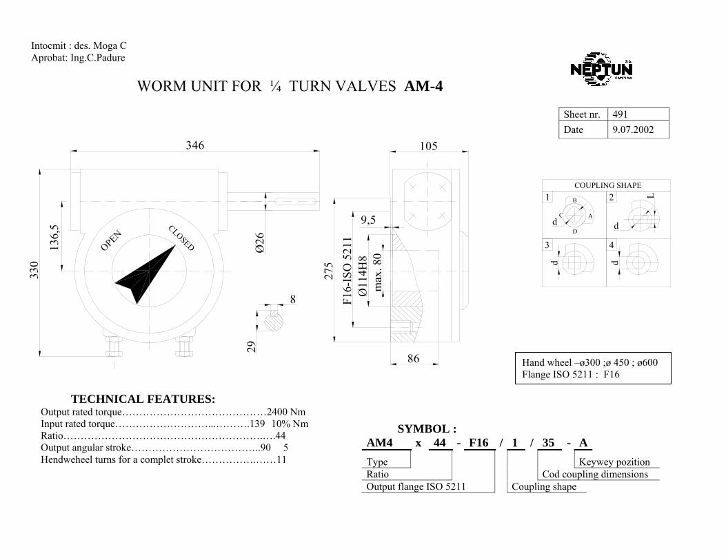
WORM UNIT FOR ¼ TURN VALVES AM-4
SYMBOL :
AM4 x 44 - F16 / 1 / 35 - A Type Keywey pozition Ratio Cod coupling dimensions Output flange ISO 5211 Coupling shape
Sheet nr. 491 Date 9.07.2002
Intocmit : des. Moga C Aprobat: Ing.C.Padure
TECHNICAL FEATURES: Output rated torque……………………………………2400 Nm Input rated torque………………………...……….139±10% Nm Ratio………………………………………………….….44 Output angular stroke………………………………..90°±5° Hendweheel turns for a complet stroke…………….……11
d
d
d
Dd
1
AC
B L2
3 4
COUPLING SHAPE
Hand wheel –ø300 ;ø 450 ; ø600 Flange ISO 5211 : F16
346
330
136,
5
OPEN
275
86
29
F16-
ISO
521
1
Ø26
CLOSED
8
105
max
. 80
Ø11
4H8
9,5
Page 31
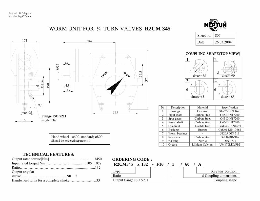
WORM UNIT FOR ¼ TURN VALVES R2CM 345
ORDERING CODE :
R2CM345 x 132 - F16 / 1 / 60 / A Type Keyway position Ratio d-Coupling dimensions Output flange ISO 5211 Coupling shape
Sheet no. 807
Date 26.03.2004
Intocmit : D.Calugaru Aprobat: Ing.C.Padure
TECHNICAL FEATURES: Output rated torque[Nm]……………….........................3450 Input rated torque[Nm]………………...................105±10% Ratio………………………………….............................132 Output angular stroke………………………..............90°±5° Handwheel turns for a complete stroke…………….……33
d d
L
d d
1
3
2
4dmax=85 dmax=90
dmax=65 dmax=85
COUPLING SHAPE(TOP VIEW)
Hand wheel –ø600-standard; ø800 Should be ordered separately !
Nr Description Material Specification 1 Housings Cast iron GG-25-DIN 1691 2 Input shaft Carbon Steel C45-DIN17200 3 Spur gears Carbon Steel C45-DIN17200 4 Worm shaft Carbon Steel C45-DIN17200 5 Quadrant Ductile Iron GGG40-DIN1693 6 Bushing Bronze CuSn6-DIN17662 7 Worm bearings - 51205 DIN 711 8 Set-screw Carbon Steel Gr8.8-DIN916 9 “O”ring Nitrile DIN 3771 10 Grease Lithium-Calcium UM170LiCaPb2
d Ø11
4
max.95
116
9,5
171
Ø25
SHUTOPEN
Flange ISO 5211single F16
117
190 45
44
384
37413
6,5
275
Page 32
WORM UNIT FOR ¼ TURN VALVES R2CM 425
ORDERING CODE :
R2CM425 x 168 - F16 / 1 / 60 - A Type Keywey pozition Ratio d-Coupling dimensions Output flange ISO 5211 Coupling shape
Sheet nr. 808 Date 26.03.2004
Intocmit :C.Buldan Aprobat: Ing.C.Padure
TECHNICAL FEARURES: Output rated torque[Nm]………………......…….……4250 Input rated torque[Nm…………………………100 ] ±10% Ratio…………………………………......……………...168 Output angular stroke………………………....……..90°±5° Hendweheel turns for a complet stroke…………………42 Capsulation …………………………………………..IP54
Handwheel –ø600-standard; ø800 Should be ordered separately !
OPEN SHUT
Flange ISO 5211single F16
d d
L
d d
1
3
2
4dmax=90 dmax=100
dmax=75 dmax=90
COUPLING SHAPE(TOP VIEW)
Nr Description Material Specification 1 Housings Cast iron GG-25-DIN 1691 2 Input shaft Carbon Steel C45-DIN17200 3 Spur gears Carbon Steel C45-DIN17200 4 Worm shaft Carbon Steel C45-DIN17200 5 Quadrant Ductile Iron GGG40-DIN1693 6 Bushing Bronze CuSn6-DIN17662 7 Worm bearings - 51207 DIN 711 8 Set-screw Carbon Steel Gr8.8-DIN916 9 “O”ring Nitrile DIN 3771 10 Grease Lithium-Calcium UM170LiCaPb2
Page 33
WORM UNIT FOR ¼ TURN VALVES R2CM 540
ORDERING CODE :
R2CM 540 x 210 - F16 / 1 / 60 - A Type Keywey pozition Ratio d-Coupling dimensions Output flange ISO 5211 Coupling shape
Sheet nr. 809 Date 24.02.2004
Intocmit :D.Calugaru Aprobat: Ing.C.Padure
TECHNICAL FEARURES: Output rated torque[Nm]………………......…….…..5400 Input rated torque[Nm………………………..100 ] ±10% Ratio…………………………………......…………….210 Output angular stroke………………………....…….90°±5° Hendweheel turns for a complet stroke………………52,5 Capsulation ………………………………………….IP54
Handwheel –ø600-standard; ø800 Should be ordered separately !
d d
L
d d
1
3
2
4dmax=90 dmax=100
dmax=75 dmax=90
COUPLING SHAPE(TOP VIEW)
Nr Description Material Specification 1 Housings Cast iron GG-25-DIN 1691 2 Input shaft Carbon Steel C45-DIN17200 3 Spur gears Carbon Steel C45-DIN17200 4 Worm shaft Carbon Steel C45-DIN17200 5 Quadrant Ductile Iron GGG40-DIN1693 6 Bushing Bronze CuSn6-DIN17662 7 Worm bearings - 51207 DIN 711 8 Set-screw Carbon Steel Gr8.8-DIN916 9 “O”ring Nitrile DIN 3771 10 Grease Lithium-Calcium UM170LiCaPb2
OPEN SHUT
Flange ISO 5211single F16
Page 34
WORM UNIT FOR ¼ TURN VALVES R2CM 759
ORDERING CODE :
R2CM-759 x 250 - F25 / 1 / 60 - A Type Keyway position Ratio d-Coupling dimensions Output flange ISO 5211 Coupling shape
Sheet no. 810 Date 24.02.2004
Intocmit :Istrate Gh. Aprobat: Ing.C.Padure
TECHNICAL FEATURES: Output rated torque[Nm]………………......………………7590 Input rated torque[Nm]……………….....…………….120±10% Ratio…………………………………..........………………..250 Output angular stroke………………………......………..90°±5° Handwheel turns for a comoplet stroke………………….62.5 Capsulation…………………………………………….….IP54
COUPLING SHAPE(TOP VIEW) p g p p g p
d d
L
d d
1
3
2
4dmax=115 dmax=125
dmax=88 dmax=115
Nr Description Material Specification 1 Housings Cast iron GG-25-DIN 1691 2 Input shaft Carbon Steel C45-DIN17200 3 Spur gears Carbon Steel C45-DIN17200 4 Worm shaft Carbon Steel C45-DIN17200 5 Quadrant Ductile Iron GGG40-DIN1693 6 Bushing Brass CuZn37-DIN17662 7 Input bearings - 6005 DIN 625 8 Worm bearings - 51207 DIN 711 9 Set-screw Carbon Steel Gr8.8-DIN916 10 “O”ring Nitrile DIN 3771 11 Grease Lithium-Calcium UM170LiCaPb2 Welded handwheel-Φ450-standard :Φ600
Should be ordered separately
381
426 15
2,4
305
OPEN SHUT
44
152,
422
2 d
9,5
Flange ISO 5211single F25 147
max.90
128
45
Ø25
-0.0
50.
15
171
Page 35
ORDERING CODE :
R2CM 897 x 300 - F30 / 1 / 60 - A Type Keywey pozition Ratio d- Coupling dimensions Output flange ISO 5211 Coupling shape
Sheet no. 811
Date 24.02.2004
Intocmit : Ing. Bruder O. Aprobat: Ing.Padure C.
TEHNICAL FEATURES: Output rated torque[Nm]……………......….8970 Input rated torque[Nm]…...….................120±10% Ratio…..…………………………………......300 Output angular stroke…..…………………90°±5° Handwheel turns for a complet stroke………..75 Capsulation………………………………...IP54
Handwheel –ø600standard ;ø800 Should be ordered separately
WORM UNIT FOR ¼ TURN VALVES R2CM 897
d d
L
d d
1
3
2
4dmax=130 dmax=148
dmax=92 dmax=130
COUPLING SHAPE(TOP VIEW)COUPLING SHAPE(TOP VIEW)
Nr Description Material Specification 1 Housings Cast iron GG-25-DIN 1691 2 Input shaft Carbon Steel C45-DIN17200 3 Spur gears Carbon Steel C45-DIN17200 4 Worm shaft Carbon Steel C45-DIN17200 5 Quadrant Ductile Iron GGG40-DIN1693 6 Bushing Bronz CuSn6-DIN17662 7 Input bearings - 6005-DIN625 8 Worm bearings - 51309 DIN711 9 Set-screw Carbon Steel Gr8.8-DIN916
10 “O”ring Nitrile DIN 3771 11 Grease Lithium-Calcium UM170LiCaPb2
Flange ISO5211single F25 or F30
max.86
354
Ø25C
LOSE
D
OPEN
OPEN
117
6
Ø17
0Ø
d
Ø30
5
45
44
455
356
181
CLO
SED
189
Page 36
ORDERING CODE :
R2CM 1200 x 450 - F30 / 1 / 60 - A Type Keywey pozition Ratio d- Coupling dimensions-key acc.to DIN 6885 Output flange ISO 5211 Coupling shape
Sheet no. 812a
Date 25.03.2005
TEHNICAL FEATURES: Output rated torque[Nm]……………......…12000 Input rated torque[Nm]…...….................100±10% Ratio…..…………………………………......450 Output angular stroke…..………………..90°±5° Handwheel turns for a complet stroke……..112,5 Capsulation…………………………………IP54
Handwheel –ø600standard ;ø800 Should be ordered separately
WORM UNIT FOR ¼ TURN VALVES R2CM 1200
d d
L
d d
1
3
2
4dmax=130 dmax=148
dmax=92 dmax=130
COUPLING SHAPE(TOP VIEW)
Nr Description Material Specification 1 Housings Cast iron GG-25-DIN 1691 2 Input shaft Carbon Steel C45-DIN17200 3 Spur gears Carbon Steel C45-DIN17200 4 Worm shaft Carbon Steel C45-DIN17200 5 Quadrant Ductile Iron GGG40-DIN1693 6 Bushing Bronz CuSn6-DIN17662 7 Input bearings - 6005-DIN625 8 Worm bearings - 51309 DIN711 9 Set-screw Carbon Steel Gr8.8-DIN916
10 “O”ring Nitrile DIN 3771 11 Grease Lithium-Calcium UM170LiCaPb2
CLO
SED
Flange ISO5211single F25 or F30
CLO
SED
OPEN
OPEN
356
455
181
Ø29
8
max.128189
41Ø32
471,5
4565
Ød
Ø17
0
6
Page 37
ORDERING CODE :
R2CM 1600 x 369 - F30 / 1 / 60 - A Type Keywey pozition Ratio d- Coupling dimensions Output flange ISO 5211 Coupling shape
Sheet no. 813
Date 24.02.2004
Intocmit : D.Calugaru Aprobat: Ing.Padure C.
TEHNICAL FEATURES: Output rated torque[Nm]……………....……..16000 Input rated torque[Nm]…...…......………….118/170±10% Ratio…..…………………………………….540/369 Output angular stroke…..……………………90°±5° Handwheel turns for a complet stroke……..135/92,5 Capsulation…………………………………..IP54
Handwheel –ø600standard ;ø800 Should be ordered separately
WORM UNIT FOR ¼ TURN VALVES R2CM 1600
d d
L
d d
1
3
2
4dmax=130 dmax=148
dmax=92 dmax=130
COUPLING SHAPE(TOP VIEW)
Nr Description Material Specification
1 Housings Cast iron GG-25-DIN 1691 2 Input shaft Carbon Steel C45-DIN17200 3 Spur gears Carbon Steel C45-DIN17200 4 Worm shaft Carbon Steel C45-DIN17200 5 Quadrant Ductile Iron GGG40-DIN1693 6 Bushing Bronz CuSn6-DIN17662 7 Input bearings - 6005-DIN625 8 Worm bearings - 51309 DIN711 9 Set-screw Carbon Steel Gr8.8-DIN916 10 “O”ring Nitrile DIN 3771 11 Grease Lithium-Calcium UM170LiCaPb2
356
455
354
Ø29
8
max.128189
Flange ISO5211single F25 or F30
Ød
Ø17
0
641Ø32
5065
CLO
SED
181
CLO
SED
OPEN
OPEN
Page 38
ORDERING CODE :
R2CM 2000 x 720 - F30 / 1 / 60 - A Type Keywey pozition Ratio d- Coupling dimensions Output flange ISO 5211 Coupling shape
Sheet no. 814
Date 24.02.2004
Intocmit : D.Calugaru Aprobat: Ing.Padure C.
TEHNICAL FEATURES: Output rated torque[Nm]……………....……..20000 Input rated torque[Nm]…...…......………….110/75±10% Ratio…..……………………………………720/1080 Output angular stroke…..……………………90°±5° Handwheel turns for a complet stroke……..180/270 Capsulation…………………………………..IP54
Handwheel –ø600standard ;ø800 Should be ordered separately
WORM UNIT FOR ¼ TURN VALVES R2CM 2000
d d
L
d d
1
3
2
4dmax=165 dmax=175
dmax=123 dmax=165
COUPLING SHAPE(TOP VIEW)
Nr Description Material Specification
1 Housings Cast iron GG-25-DIN 1691 2 Input shaft Carbon Steel C45-DIN17200 3 Spur gears Carbon Steel C45-DIN17200 4 Worm shaft Carbon Steel C45-DIN17200 5 Quadrant Ductile Iron GGG40-DIN1693 6 Bushing Bronz CuSn6-DIN17662 7 Input bearings - 6005-DIN625 8 Worm bearings - ANK6590- DIN711 9 Set-screw Carbon Steel Gr8.8-DIN916 10 “O”ring Nitrile DIN 3771 11 Grease Lithium-Calcium UM170LiCaPb2
556
237
Ø36
0
311 Flange ISO5211single F30 or F35
65
466
Ø3250
41
430
CLO
SED
227,5
max.140
9,5Ø
200
Ød
CLO
SED
OPEN
OPEN
Page 39
WORM UNIT FOR ¼ TURN VALVES R2CM 3000
ORDERING CODE :
R2CM3000 x 720 - F35 / 1 / 90 - A Type Keyway position Ratio d-Coupling dimensions Output flange ISO 5211 Coupling shape
Sheet no. 815a
Date 24.02.2004
Intocmit : ing.V.Rosianu Aprobat: Ing.C.Padure
TECHNICAL FEATURES: Output rated torque[Nm]……………….......................…...30000 Input rated torque[Nm]………………...........................180±10% Ratio…………………………………...........................……..720 Output angular stroke………………………................….90°±5° Handwheel turns for a complete stroke…………….………..180 Capsulation…………………………………………………IP 54
d d
L
d d
1
3
2
4dmax=160 dmax=170
dmax=120 dmax=160
COUPLING SHAPE(TOP VIEW)
Handwheel – ø600 – standard; ø800 Should be ordered separately!
Nr Description Material Specification
1 Housings Cast iron GG-25-DIN 1691 2 Input shaft Carbon Steel C45-DIN17200 3 Spur gears Carbon Steel C45-DIN17200 4 Worm shaft Case harden. steel 16 MnCr 5-DIN17200 5 Quadrant Ductile Iron GGG40-DIN1693 6 Bushing Bronze CuSn6-DIN17662 7 Input bearings - 6007, 6306 - DIN 625 8 Worm bearings - 81112 DIN 722 9 Set-screw Carbon Steel Gr8.8-DIN916 10 “O”ring Nitrile DIN 3771 11 Grease Lithium-Calcium UM170LiCaPb2
Ø20
0 d
243
CLOSED
CLOSED
636
555max.188
Flange ISO 5211single F30 or F35
OPEN
488
Ø32
65
310
8OPEN
Page 40
WORM UNIT FOR ¼ TURN VALVES R2CM 4000
ORDERING CODE :
R2CM 4000 x 1200 - F35 / 1 / 90 - A Type Keyway position Ratio d-Coupling dimensions Output flange ISO 5211 Coupling shape
Sheet no. 816a
Date 24.02.2004
Intocmit : D.Calugaru Aprobat: Ing.C.Padure
TECHNICAL FEATURES: Output rated torque[Nm]……………….......................…...40000 Input rated torque[Nm]………………...........................145±10% Ratio…………………………………...........................……1200 Output angular stroke………………………................….90°±5° Handwheel turns for a complete stroke…………….………..300 Capsulation…………………………………………………IP 54
d d
L
d d
1
3
2
4dmax=160 dmax=170
dmax=120 dmax=160
COUPLING SHAPE(TOP VIEW)
Handwheel – ø600 – standard; ø800 Should be ordered separately!
Nr Description Material Specification
1 Housings Cast iron GG-25-DIN 1691 2 Input shaft Carbon Steel C45-DIN17200 3 Spur gears Carbon Steel C45-DIN17200 4 Worm shaft Case harden. steel 16 MnCr 5-DIN17200
5 Quadrant Ductile Iron GGG40-DIN1693 6 Bushing Bronze CuSn6-DIN17662 7 Input bearings - 6007, 6306 - DIN 625 8 Worm bearings - 81112 DIN 722 9 Set-screw Carbon Steel Gr8.8-DIN916
10 “O”ring Nitrile DIN 3771 11 Grease Lithium-Calcium UM170LiCaPb2
CLOSED
CLOSED
Flange ISO 5211single F30 or F35
OPEN
OPEN
636
243d
Ø20
0
555max.188
488
Ø32
65
310
8
Page 41
WORM UNIT FOR ¼ TURN VALVES R2CM 5000
ORDERING CODE :
R2CM 5000 x 1977 - F35 / 1 / 90 - A Type Keyway position Ratio d-Coupling dimensions Output flange ISO 5211 Coupling shape
Sheet no. 817a
Date 24.02.2004
Intocmit : D.Calugaru Aprobat: Ing.C.Padure
TECHNICAL FEATURES: Output rated torque[Nm]……………….......................…...50000 Input rated torque[Nm]………………...........................110±10% Ratio…………………………………...........................……1977 Output angular stroke………………………................….90°±5° Handwheel turns for a complete stroke…………….………..495 Capsulation…………………………………………………IP 54
d d
L
d d
1
3
2
4dmax=160 dmax=170
dmax=120 dmax=160
COUPLING SHAPE(TOP VIEW)
Handwheel – ø600 – standard; ø800 Should be ordered separately!
Nr Description Material Specification
1 Housings Cast iron GG-25-DIN 1691 2 Input shaft Carbon Steel C45-DIN17200 3 Spur gears Carbon Steel C45-DIN17200 4 Worm shaft Case harden. steel 16 MnCr 5-DIN17200 5 Quadrant Ductile Iron GGG40-DIN1693 6 Bushing Bronze CuSn6-DIN17662 7 Input bearings - 6007, 6306 - DIN 625 8 Worm bearings - 81112 DIN 722 9 Set-screw Carbon Steel Gr8.8-DIN916
10 “O”ring Nitrile DIN 3771 11 Grease Lithium-Calcium UM170LiCaPb2
CLOSED
CLOSED
Flange ISO 5211single F30 or F35
OPEN
OPEN
636
243
dØ
200
555max.188
488
Ø32
65
310
8
Page 42
WORM UNIT FOR ¼ TURN VALVES R2CM 6000
ORDERING CODE :
R2CM 6000 x 1440 - F40 / 1 / 90 - A Type Keyway position Ratio d-Coupling dimensions Output flange ISO 5211 Coupling shape
Sheet no. 818a
Date 24.02.2004
Intocmit : D.Calugaru Aprobat: Ing.C.Padure
TECHNICAL FEATURES: Output rated torque[Nm]……………….......................…...60000 Input rated torque[Nm]………………...........................160±10% Ratio…………………………………...........................……1440 Output angular stroke………………………................….90°±5° Handwheel turns for a complete stroke…………….………..360 Capsulation…………………………………………………IP 54
d d
L
d d
1
3
2
4dmax=200 dmax=210
dmax=140 dmax=200
COUPLING SHAPE(TOP VIEW)
Handwheel – ø600 – standard; ø800 Should be ordered separately!
Nr Description Material Specification
1 Housings Cast iron GG-25-DIN 1691 2 Input shaft Carbon Steel C45-DIN17200 3 Spur gears Carbon Steel C45-DIN17200 4 Worm shaft Case harden. steel 16 MnCr 5-DIN17200 5 Quadrant Ductile Iron GGG40-DIN1693 6 Bushing Bronze CuSn6-DIN17662 7 Input bearings - 6007, 6306 - DIN 625 8 Worm bearings - 51312 DIN 722 9 Set-screw Carbon Steel Gr8.8-DIN916
10 “O”ring Nitrile DIN 3771 11 Grease Lithium-Calcium UM170LiCaPb2
Flange ISO 5211single F40
CLO
SED
OPEN
CLO
SED
OPEN
Page 43
WORM UNIT FOR ¼ TURN VALVES R2CM 6500
ORDERING CODE :
R2CM 6500 x 1490 - F40 / 1 / 90 - A Type Keyway position Ratio d-Coupling dimensions Output flange ISO 5211 Coupling shape
Sheet no. 819a
Date 24.02.2004
Intocmit : D.Calugaru Aprobat: Ing.C.Padure
TECHNICAL FEATURES: Output rated torque[Nm]……………….......................…...65000 Input rated torque[Nm]………………...........................175±10% Ratio…………………………………...........................……1490 Output angular stroke………………………................….90°±5° Handwheel turns for a complete stroke…………….……..372,5 Capsulation……………………………………………….IP 54
d d
L
d d
1
3
2
4dmax=200 dmax=210
dmax=140 dmax=200
COUPLING SHAPE(TOP VIEW)
Handwheel – ø600 – standard; ø800 Should be ordered separately!
Nr Description Material Specification
1 Housings Cast iron GG-25-DIN 1691 2 Input shaft Carbon Steel C45-DIN17200 3 Spur gears Carbon Steel C45-DIN17200 4 Worm shaft Case harden. steel 16 MnCr 5-DIN17200 5 Quadrant Ductile Iron GGG40-DIN1693 6 Bushing Bronze CuSn6-DIN17662 7 Input bearings - 6007, 6306 - DIN 625 8 Worm bearings - 51312 DIN 722 9 Set-screw Carbon Steel Gr8.8-DIN916
10 “O”ring Nitrile DIN 3771 11 Grease Lithium-Calcium UM170LiCaPb2
OPEN
Flange ISO 5211single F40
CLOSED
CLOSED
OPEN
Page 44
WORM UNIT FOR ¼ TURN VALVES R2CM 8500
ORDERING CODE :
R2CM 8500 x 1560 - F40 / 1 / 90 - A Type Keyway position Ratio Coupling dimensions code Output flange ISO 5211 Coupling shape
Sheet no. 820a
Date 24.02.2004
Intocmit : D.Calugaru Aprobat: Ing.C.Padure
TECHNICAL FEATURES: Output rated torque[Nm]………………......................85000 Input rated torque[Nm]……………….....................210/125±10% Ratio…………………………………....................1560/2700 Output angular stroke………………………..............90°±5° Handwheel turns for a complete stroke……………390/675 Capsulation…………………………………………IP 54
d d
L
d d
1
3
2
4dmax=200 dmax=210
dmax=140 dmax=200
COUPLING SHAPE(TOP VIEW)
Handwheel – ø600 – standard; ø800 Should be ordered separately!
Nr Description Material Specification
1 Housings Cast iron GG-25-DIN 1691 2 Input shaft Carbon Steel C45-DIN17200 3 Spur gears Carbon Steel C45-DIN17200 4 Worm shaft Case harden. steel 16 MnCr 5-DIN17200 5 Quadrant Ductile Iron GGG40-DIN1693 6 Bushing Bronze CuSn6-DIN17662 7 Input bearings - 6007, 6306 - DIN 625 8 Worm bearings - 51312 DIN 722 9 Set-screw Carbon Steel Gr8.8-DIN916
10 “O”ring Nitrile DIN 3771 11 Grease Lithium-Calcium UM170LiCaPb2
OPEN
Flange ISO 5211single F40
CLOSED
CLOSED
OPEN
Page 45
DECLUTCHABLE ”1/4-TURN” –ACTUATOR RMD 0A Sheet nr. 614b
Date 05.03.2003
TECHNICAL FEATURES: Output rated torque……………………125 Nm Input torque……………………………8,8 Nm Ratio…………………………………………41 Output angular stroke…………………..90°±5° Handwheel turns for a complete stroke….10,25 Capsulation………………………………IP 65 M t i l t S ifi ti 128
ORDERING CODE: RMD-0A x F07 - C15 / F05 - C15 x 30 - 92
Type L-Shaft length Valve side ISO 5211 l-length d-Valve coupling shape d-Coupling shape & dim. –actuator side Thru holes for actuator side ISO 5211
dØ35Ø90
3
max.33105
l=30-standard
45°45°
ACTUATOR SIDEThru holes for F05;F07-ISO 5211
VALVE SIDE F05;F07-ISO5211
d
160
4250
L=92-standardL=151
20
Ø100
Ø4,52
5
2 28
Ø15
-0,0
5-0
,1
W
V
d
View "V";"W"Coupling shapePosition "closed"
M
C
dmax=17
dmax=18
R
dmax=25S d
ddmax=17
CR d
Alluminium Handwheel - 140-standard Should be ordered separately
Page 46
Sheet nr. 615b Date 05.03.2003
DECLUTCHABLE ”1/4-TURN” –ACTUATOR RMD 1A Sheet nr. 615b
Date 05.03.2003
Intocmit :Sing. Buldan C. Aprobat: Ing.C.Padure
TECHNICAL FEATURES: Output rated torque……………………270 Nm Input torque…………………………...22,5 Nm Ratio………………………………………40 Output angular stroke…………………..90°±5° Handwheel turns for a complete stroke…...10 Capsulation……………………………..IP 65 M t i l t S ifi ti 128
VALVE SIDEFO7;F10 ISO 5211
ACTUATOR SIDEThru holes for FO7;F10- ISO 5211
d
dmax=25 ; Smax=
Mdmax=19
C
d
S ddmax=25
Rdmax=19
CR
View "V";"W"Coupling shapePosition "closed"
d
Alluminium Handweel Ø225-Standard Should be ordered separately
ORDERING CODE: RMD-1A x F10 - C17 / F07 - C17 x 35 - 112
Type L-Shaft length Valve side ISO 5211 l-length d-Valve coupling shape d-Coupling shape & dim. –actuator side Thru holes for actuator side ISO 5211
Page 47
DECLUTCHABLE ”1/4-TURN” –ACTUATOR RMD 2A
Sheet nr. 616b Date 05.03.2003
Intocmit :D.Calugaru Aprobat: Ing.C.Padure
TECHNICAL FEATURES: Output rated torque……………………800 Nm Input torque………………………….….55 Nm Ratio…………………………………………48 Output angular stroke…………………..90°±5° Handwheel turns for a complete stroke….10,25 Capsulation………………………………IP 65 Materials acc.to Specification nr.128
VALVE SIDE F10;F12 ISO 5211
ACTUATOR SIDEThru holes for F10;F12- ISO 5211
d
dmax=36 ;
Mdmax=32
C
d
S ddmax=36
Rdmax=32
CR
View "V";"W"Coupling shapePosition "closed"
d
Alluminium Handweel Ø225-Standard Should be ordered separately
ORDERING CODE: RMD-2A x F12 - C25 / F10 - C25 x 40 - 131
Type L-Shaft length Valve side ISO 5211 l-length d-Valve coupling shape d-Coupling shape & dim. –actuator side Thru holes for actuator side ISO 5211
Page 48
DECLUTCHABLE ”1/4-TURN” –ACTUATOR RMD 3A
Sheet nr. 617b Date 05.03.2003
Intocmit :Sing. D.Calugaru Aprobat: Ing.C.Padure
TECHNICAL FEATURES: Output rated torque…………………..1150 Nm Input torque………………………….….75 Nm Ratio…………………………………………49 Output angular stroke…………………..90°±5° Hand wheel turns for a complete stroke….10.25 Capsulation……………………………....IP 65 Materials acc. to. Specification nr.128
163
dØ85Ø15
0
VALVE SIDE F12 ISO 5211
max.45
6
d
ACTUATOR SIDEThru holes for F12;F14-ISO 5211
l-45-standard
Ø22
-0,0
5-0
,1
L=180-standardL=211
33-standard42
Ø6
8
Ø178
"W" "V"
7385
,7
281
Hand wheel - A450-standard; -A350 Should be ordered separately
d
View "V";"W"Coupling shapePosition "closed"
Mdmax=36
C
d
dSdmax=65
Rdmax=36
dCR
dmax=48
ORDERING CODE: RMD-3A x F12 - C36 / F12 - C36 x 45 - 180
Type L-Shaft length Valve side ISO 5211 l-length d-Valve coupling shape d-Coupling shape & dim. –actuator side Thru holes for actuator side ISO 5211
Page 49
DECLUTCHABLE ”1/4-TURN” –ACTUATOR RMD 4A
Sheet nr. 618b Date 05.03.2003
Intocmit :Sing. D.Calugaru Aprobat: Ing.C.Padure
TECHNICAL FEATURES: Output rated torque…………………...2500 Nm Input torque…………………………... 190 Nm Ratio…………………………………………44 Output angular stroke…………………..90°±5° Hand wheel turns for a complete stroke……11 Capsulation………………………………IP 65 Materials acc. to. Specification 128
Ø17
5
45°
VALVE SIDE F12;F14- ISO 5211
45°
ACTUATOR SIDEThru holes for F14;F16-ISO 5211
195
max.59
Ø10
0d
l-50-standard
d
382
Ø26
-0,0
5-0
,1
Ø275
L=221-standardL=239
42Ø7
8
98
142,
54
"W""V"
Hand wheel - A600-standard Should be ordered separately
d
View "V";"W"Coupling shapePosition "closed"
M
C
dmax=60
dmax=80
R
dmax=60S d
ddmax=60
CR d
ORDERING CODE: RMD-4A x F14 - C50 / F14 - C50 x 55 - 221
Type L-Shaft length Valve side ISO 5211 l-length d-Valve coupling shape d-Coupling shape & dim. –actuator side Thru holes for actuator side ISO 5211
Page 50
DECLUTCHABLE ”1/4-TURN” –ACTUATOR RMD 5
Sheet nr. 619b Date 05.03.2003
Intocmit :Sing. D.Calugaru Aprobat: Ing.C.Padure
TECHNICAL FEATURES: Output rated torque…………………...4000 Nm Input torque…………………………... 104 Nm Ratio………………………………………127,9 Output angular stroke…………………..90°±5° Handwheel turns for a complete stroke….10.25 Capsulation………………………………IP 65
VALVE SIDE F16 ISO 5211
Thru hls.for F16-ISO 5211
Handwheel - A600 Should be ordered separately
d
View "V";"W"Coupling shapePosition "closed"
dmax=80 ; Smax=
Mdmax=60
C
d
dSdmax=60
Rdmax=60
dCR
ORDERING CODE: RMD-5 x F16 - C60 / F16 - C60 x 80 - 370
Type L-Shaft length Valve side ISO 5211 l-length d-Valve coupling shape d-Coupling shape & dim. –actuator side Thru hls. for actuator side ISO 5211
Page 51
DECLUTCHABLE ”1/4-TURN” –ACTUATOR RMD 6
Sheet nr. 620b Date 05.03.2003
Intocmit :Sing. D.Calugaru Aprobat: Ing.C.Padure
TECHNICAL FEATURES: Output rated torque…………………...8000 Nm Input torque…………………………... 144 Nm Ratio………………………………………..216 Output angular stroke…………………..90°±5° Handwheel turns for a complete stroke….10,25 Capsulation………………………………IP 65
VA
LVE
SID
E F
16;F
25- I
SO52
11
ACTUATOR SIDEThru holes for F25-ISO 5211
Handwheel - A600 Should be ordered separately
d
View "V";"W"Coupling shapePosition "closed"
dmax=95 ; Smax=
Mdmax=70
C
d
dSdmax=70
Rdmax=70
dCR
ORDERING CODE: RMD-6 x F25 - C70 / F25 - C70 x 80 - 320
Type L-Shaft length Valve side ISO 5211 l-length d-Valve coupling shape d-Coupling shape & dim. –actuator side Thru holes for actuator side ISO 5211
Page 52
DECLUTCHABLE ”1/4-TURN” –ACTUATOR RMD 7
Sheet nr. 621b Date 05.03.2003
Intocmit :Sing. D.Calugaru Aprobat: Ing.C.Padure
TECHNICAL FEATURES: Output rated torque…………………16000 Nm Input torque…………………………...163 Nm Ratio……………………………………..379,5 Output angular stroke…………………..90°±5° Handwheel turns for a complete stroke….10,25 Capsulation………………………………IP 65
Handwheel - A800 Should be ordered separately
d
View "V";"W"Coupling shapePosition "closed"
M
C
dmax=90
dmax=125
R
dmax=125S d
ddmax=90
CR d
ORDERING CODE: RMD-7 x F30 - C70 / F30 - C70 x 80 - 370
Type L-Shaft length Valve side ISO 5211 l-length d-Valve coupling shape d-Coupling shape & dim. –actuator side Thru holes for actuator side ISO 5211
VA
LVE
SID
E F
25;F
30-I
SO 5
211
ACTUATOR SIDEThru holes for F30-ISO 5211
Page 53
DECLUTCHABLE ”1/4-TURN” –ACTUATOR RMD 125M
Sheet nr. 466b Date 01.09.2006
Issued :D.Calugaru Aproved: Ing.C.Padure
TECHNICAL FEATURES: Output rated torque……………………..2500 Nm Input torque……………………………....110 Nm Ratio………………………………….……76 Output angular stroke………………………90°±5° Hand wheel turns for a complete stroke…...19 C l ti IP67
Nr Description Material Specification 1 Housings Cast iron GG-25-DIN 1691 4 Quadrant Ductile Iron GGG40-DIN1693 5 Input shaft Stainless Steel A4 X5CrNiMo17-12-2/AISI 316 7 Sleeves Bronze-CuSn 6 DIN 17662 8 Bushing Stainless Steel A4 X5CrNiMo17-12-2/AISI 316 9 Lever Stainless Steel A4 X5CrNiMo17-12-2/AISI 316 10 Locking screw Stainless Steel A4 X5CrNiMo17-12-2/AISI 316 11 Driver Stainless Steel X20Cr13-DIN 17440 12 Set screws Stainless Steel A4 X5CrNiMo17-12-2/AISI 316 13 Pin Stainless Steel A4 X5CrNiMo17-12-2/AISI 316 18 Screw Stainless Steel A4 X5CrNiMo17-12-2/AISI 316 19 Nut Stainless Steel A4 X5CrNiMo17-12-2/AISI 316 21 Grease Lithium-Calcium UM170LiCaPb2 26 Parallel key Stainless Steel A4 X5CrNiMo17-12-2/AISI 316
Input bearings - 51205-DIN 625 “O” ring Nitrile-DIN 3771 Nitrile-DIN 3771
Aluminum hand wheel –ø350-standard Should be ordered separately!
d
View "V";"W"Coupling shapePosition "closed"
dmax=78 ; Smax=
Mdmax=55
C
d
dSdmax=60
Rdmax=55
dCR
410
45°
VALVE SIDEF14-ISO 5211
ACTUATOR SIDEThru holes for F14-ISO 5211
305
Ø17
5
Ø17
5
L=234-standard
45°
9
10
5 26
Ø26
-0,0
5-0
,1
Ø245
l-50-standard
max.59
160
Ø90 50 50
11
1
13;18 4
19
130
7;8
12
42
Ø7
8
106,
5
ORDERING CODE: RMD125M x F14 - C50 / F14 - C50 x 55 - 234 Type L-Shaft length Valve side ISO 5211 l-length d-Valve coupling shape d-Coupling shape & dim. –actuator side Thru holes for actuator side ISO 5211
Page 54
TOGGLE GEAR ACTUATOR AV 2 Sheet nr. 840
Date 30.04.2004
Intocmit : D.Calugaru Aprobat: Ing.C.Padure
TECHNICAL FEATURES: Output rated torque………………………max.500 Nm Input rated torque……………………….…50±10% Nm Ratio………………………………………………...80 Output angular stroke……………………………90°±5° Hand wheel turns for a complete stroke……………..20 Capsulation………………………………………IP 54
COUPLING SHAPE(TOP VIEW)
d d
L
d d
1
3
2
4dmax=31 dmax=35
dmax=25 dmax=51
Aluminum hand wheel –ø225-standard Should be ordered separately!
Nr Description Material Specification 1 Housing Ductile Iron GGG25-DIN1693 2 Input shaft Carbon Steel C45DIN17200 3 Cranking bar Carbon Steel C45DIN17200 4 Bushing Synthered Alloy GG45-DIN 5 Set-screw Carbon Steel Gr5.8-DIN916 6 “O” ring Nitrile DIN 3771 7 Grease Lithium-Calcium UM170LiCaPb2
ORDERING CODE : AV 2 x 80 - F10 / 3 / 24
Type Ratio d-Coupling dimensions(NCI 30) Output flange ISO 5211 Coupling shape
FLANGE ISO 5211single F07 or F10duble F07+F10
OPEN
OPEN
CLOSE
Page 55
TOGGLE GEAR ACTUATOR AV 3 Sheet nr. 841
Date 30.04.2004
Intocmit : D.Calugaru Aprobat: Ing.C.Padure
TECHNICAL FEATURES: Output rated torque………………………max.2000 Nm Input rated torque……………………….…40±10% Nm Ratio………………………………………………...156 Output angular stroke……………………………90°±5° Handwheel turns for a complete stroke……………..34 Capsulation………………………………………IP 54
COUPLING SHAPE(TOP VIEW)
d d
L
d d
1
3
2
4dmax=51 dmax=56
dmax=40 dmax=51
Aluminum hand wheel –ø350-standard Should be ordered separately!
Nr Description Material Specification 1 Housing Ductile Iron GGG25-DIN1693 2 Input shaft Carbon Steel C45DIN17200 3 Cranking bar Carbon Steel C45DIN17200 4 Bushing Synthered Alloy GG45-DIN 5 Set-screw Carbon Steel Gr5.8-DIN916 6 “O” ring Nitrile DIN 3771 7 Grease Lithium-Calcium UM170LiCaPb2
ORDERING CODE : AV 3 x 156 - F10 / 3 / 24
Type Ratio d-Coupling dimensions Output flange ISO 5211 Coupling shape
CLOSE
OPEN
OPEN
FLANGE ISO5211single F10 or F14duble F10+F14
370
182,
5
Ø20
h6
0 -0,0
13
135
127
max.117
d
67
6
25 62,5
Page 56
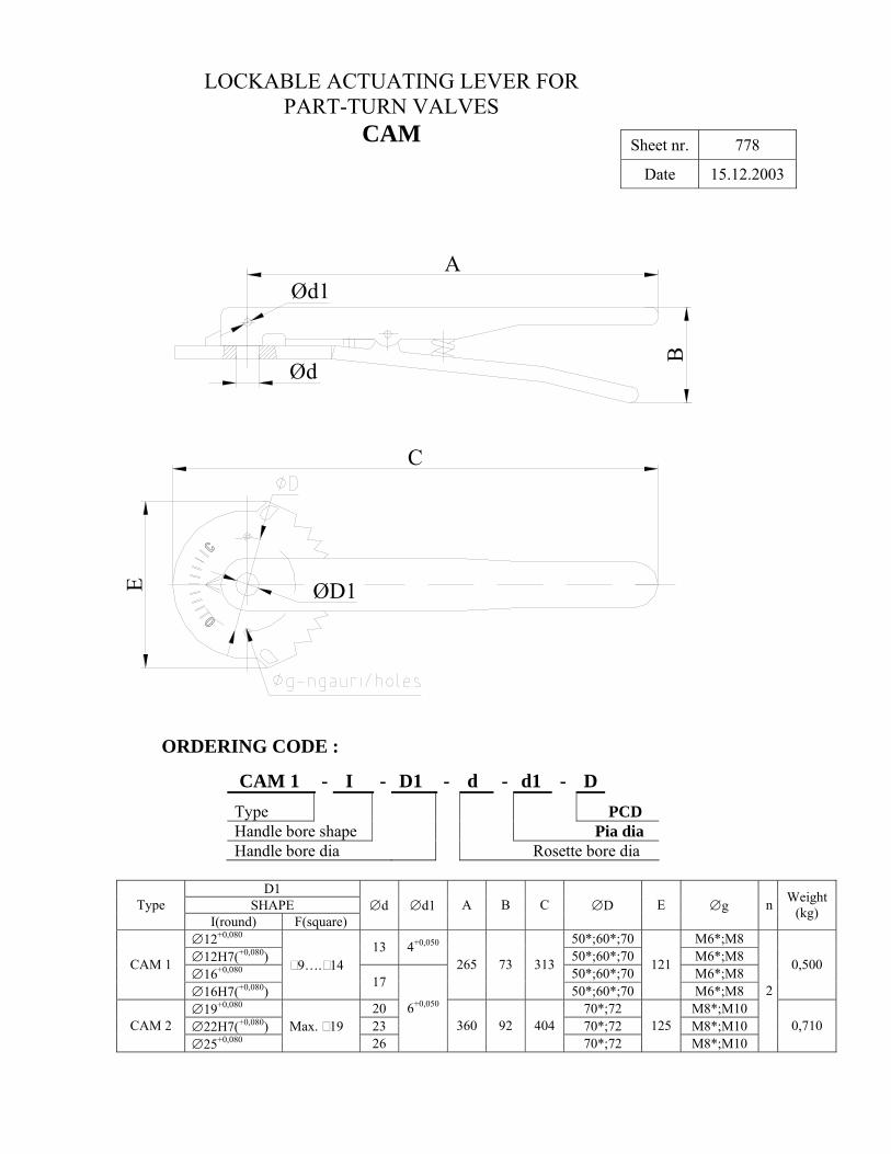
LOCKABLE ACTUATING LEVER FOR PART-TURN VALVES
CAM Sheet nr. 778
Date 15.12.2003
C
Ød
ØD1E
C
AØd1
B
ORDERING CODE :
CAM 1 - I - D1 - d - d1 - D Type PCD Handle bore shape Pia dia Handle bore dia Rosette bore dia
D1 SHAPE Type
I(round) F(square) ∅d ∅d1 A B C ∅D E ∅g n Weight
(kg)
∅12+0,080 50*;60*;70 M6*;M8 ∅12H7(+0,080)
13 4+0,050
50*;60*;70 M6*;M8 ∅16+0,080 50*;60*;70 M6*;M8 CAM 1
∅16H7(+0,080)
9…. 14 17
265 73 313
50*;60*;70
121
M6*;M8
0,500
∅19+0,080 20 70*;72 M8*;M10 ∅22H7(+0,080) 23 70*;72 M8*;M10 CAM 2 ∅25+0,080
Max. 19 26
6+0,050
360 92 404 70*;72
125 M8*;M10
2
0,710
Page 57
ROATA DE MANA RM 140
Sheet nr. 891 Date 23.09.2004
Into
cmit
:D.C
alug
aru
Apr
obat
: Ing
.C.P
adur
e
CUPLARE PS (PANA+STIFT) PG(PANA+GAURA) P-PANA S-STIFT P-PANA G-GAURA Alezaj ∅d 1,0
05,0++ b L ∅d1 b L ∅d1
∅15 5 098,0040,0
++ 2,3 2,0
0+ M6 - - -
∅12 - - - - - ∅4H8 ∅16 - - - - - ∅6H8
Material:ALUMINIU
Page 58
ROATA DE MANA RM 225Sheet nr. 892
Date 23.09.2004
Into
cmit
:D.C
alug
aru
Apr
obat
: Ing
.C.P
adur
e
SIMBOLIZARE: RM 225 x 16 - 27 / P
Tip roata Felul cuplarii(P,S,G,PS,PG)
d-diametrul gaurii l2-lungime butuc
CUPLARE PS (PANA+STIFT) PG(PANA+GAURA) P-PANA S-STIFT P-PANA G-GAURA Alezaj ∅d 1,0
05,0++ b L ∅d1 b L ∅d1
- - - - - ∅16 - - - ∅6H8
5 098,0
040,0++ 2,3 2,0
0+
M6 - - ∅4H8 ∅20 6 098,0
040,0++ 2,8 2,0
0+ M6 - - ∅6H8
Material:ALUMINIU
Page 59
Roata de mana / Handwheel AV3-06
Sheet nr. 890
Date 23.09.2004
CUPLARE PS (PANA+STIFT) PG(PANA+GAURA) P-PANA S-STIFT P-PANA G-GAURA Alezaj ∅d 1,0
05,0++ b L ∅d1 b L ∅d1
∅10-∅12 4 098,0040,0
++ 1,8 2,0
0+ M6 - -
∅17-∅22 8 098,0040,0
++ 3,3 2,0
0+ M8 - - 6H8
∅22-∅30 8 098,0040,0
++ 3,3 2,0
0+ M10 - -
Material:ALUMINIUM
bA
O P
E N
A
L
WR
CLOSE
Ø35
0
Ød
Ø50
50
45-piesa turnatal2-cota prelucrata
25
l1=l2+55
50
12d1